research on variable frequency transformer: a smart power
TRANSCRIPT

Received June 13, 2021, accepted July 15, 2021, date of publication July 26, 2021, date of current version August 3, 2021.
Digital Object Identifier 10.1109/ACCESS.2021.3099747
Research on Variable Frequency Transformer:A Smart Power Transmission TechnologyMOHD MOHSIN KHAN 1, IMDADULLAH 2, (Senior Member, IEEE), JAMEL NEBHEN 3,AND HAFIZUR RAHMAN 11Department of Electrical Engineering, Zakir Husain College of Engineering and Technology, Aligarh Muslim University, Aligarh 202002, India2Electrical Engineering Section, University Polytechnic, Faculty of Engineering and Technology, Aligarh Muslim University, Aligarh 202002, India3Prince Sattam bin Abdulaziz University, College of Computer Engineering and Sciences, Alkharj 11942, Saudi Arabia
Corresponding authors: Mohd Mohsin Khan ([email protected]) and Imdadullah ([email protected])
This work was supported by the Deanship of Scientific Research at Prince Sattam bin Abdulaziz University, Saudi Arabia.
ABSTRACT The electric power systems are interconnected for the economical and reliable operation ofpower supply systems. An interconnection of power systems can be implemented through AC and DC links.A variable frequency transformer (VFT) has emerged as an alternative for asynchronous interconnection,like back-to-back HVDC links. Unlike back-to-back HVDC links, VFT requires reduced reactive power,offers quicker incipient transient recovery, and has coherent damping ability. Various control strategieshave been proposed in the literature to achieve the controllable and reliable operation of VFT. The VFTcan be scalable for high power exchange by implementing the VFT Park model. The VFT is essentially adoubly-fed induction machine (DFIM) based system that needs slip rings and brushes in the rotor circuit.Hence, brushless doubly-fed induction machine (BDFIM) based VFT systems and their various topologiesare proposed in the literature. In this paper, a comprehensive review is carried out, which includes: powersystem networks interconnection philosophy, power flow controllers used in the interconnected networks,FACTS controllers, and HVDC link with their technical merits and limitations. A comparison of VFT withits counter technology back-to-back HVDC link is also elaborated, which suggests VFT a better optionfor asynchronous grid interconnection. Moreover, a thorough literature review is done concerning VFTconfiguration, controls, and scaling with research papers and patents. Furthermore, detailed mathematicalmodeling of the VFT system is also carried out along with the numerical simulations under both steady-stateand various fault conditions using PSCAD/EMTDC software.
INDEX TERMS Asynchronous interconnection, power flow controllers, FACTS, HVDC, variable frequencytransformer (VFT), brushless doubly-fed induction machine (BDFIM), doubly-fed induction machine(DFIM).
I. INTRODUCTIONThe fast-growing population requires industrialization at asubstantial level to cope with their needs, particularly fordeveloping and underdeveloped nations. The fast industrialdevelopment would lead to the rapid and consistent growthin energy demand [1]. In addition, a deficit of fossil fuelswould hurdle energy development, and many nations arefacing this challenge and hence looking forward to it. Onepossible solution is to expand their renewable energy basedelectricity generation. However, the successful implementa-tion of various renewable energy resources is not relatively
The associate editor coordinating the review of this manuscript and
approving it for publication was Jahangir Hossain .
easy because of their uncertain nature, and the stability of thepower grid is not assured [2]–[4].
A. MOTIVATION AND INCITEMENTTo meet enormous energy demand, most national, regional,urban, and rural grids opted for grid interconnection [5].The resulting grid interconnection offers greater reliabil-ity, thereby offering reduced electricity generation cost andimproves the power supply services [6]. In addition, the inter-connection of power networks avoids generating reserverequirements in each system. Thus, interconnection abatesinvestment in energy production or somewhat halts the needto add new capacity soon. Furthermore, the interconnectionof power system networks leads to the ease of the electricity
105588 This work is licensed under a Creative Commons Attribution 4.0 License. For more information, see https://creativecommons.org/licenses/by/4.0/ VOLUME 9, 2021

M. M. Khan et al.: Research on VFT: Smart Power Transmission Technology
market. It enables the commercialization of power throughmultiple provinces and nations. Most power system networksin the world today operate at either 50 Hz or 60 Hz frequen-cies. The integration of nearby power networks is a dynamicapproach to the global energy system today, and furtherresearch in this field is of quite an interest globally. There is adevelopment of multiple microgrids, integration of multiplerenewables to the utility grids, and the interconnection ofvarious national, regional and local power grids [7]–[10]. Dueto the above facts, many researchers and power engineers arelooking forward to various grid interconnection technologiesand different power flow controllers.
B. LITERATURE REVIEWTo interconnect two power systems, a reliable and cost-effective interconnector (link) is required. Two powersystems may be interconnected via synchronous intercon-nection and asynchronous interconnection. The synchronousinterconnection allows the interconnection of power gridsoperating at the same frequency through an AC link. Thisarrangement offers simplicity as well as economic feasibil-ity [11]. However, this method imposes complexity in theoperation of the power system. Moreover, it also imposesserious stability limitations under severe fault conditions [12].
The control of power transfer through these connectionlines is regulated by different power flow controlling devicessuch as phase-shifting transformer (PST) [13], [14], sentransformer (ST) [15], [16], rotary power flow controller(RPFC) [17], [18], and FACTS controller [19]. In the caseof PST, the power flow can be assessed by controlling theline voltage vector. However, control of power transfer isaccompanied in steps by changing the tapings of the trans-former, which ultimately results in sluggish control of power.Independent control of real and reactive power flow canbe attained by using Sen Transformer (ST) [20]. However,ST has limitations of output error and sluggish response [15],[21]. The RPFC claims better results than PST but requiresan isolated drive system for rotation of rotor shaft [22].A comparative study of various power flow controllers usedfor controlling the power flow in synchronous interconnectedpower systems is presented in Table 1.
The FACTS controller is emerging from the roots of powerelectronics to control one or more power transmission param-eters. There are various FACTS controllers which have beenevolved for the control of power transfer through AC link.The conventional FACTS controller is static var compen-sator (SVC) which is a variable impedance type. The SVCis usually placed in a shunt with the power network. More-over, the thyristor switched series reactor (TSSR), thyristor-controlled series reactor (TCSR), thyristor-controlled seriescapacitor (TCSC) are series FACTS controllers. However,drawbacks related to these controllers are the injection ofcurrent harmonics, and their sluggish response [33]. Table 2summarizes various FACTS controllers used for controllingthe power flow in the interconnected power system networks.
The other method of the interconnection of two powersystems operating at the same or different frequencies isasynchronous interconnection. A high voltage direct cur-rent (HVDC) system is a common technique to implementasynchronous interconnection. The HVDC system is eco-nomical for large distances and a huge amount of powertransfer. However, the high cost of converters, demands ofreactive power, production of harmonics, and the problems ofcircuit breaking restricts its applications [45]–[47].Moreover,HVDC link also has operating problem where low AC poweris linked on any of the two sides [48]. A summary of variousHVDC topologies used for asynchronous interconnectionsare presented in Table 3.
An asynchronous interconnection may also be made by avirtual synchronous machine (VSM) to integrate distributedgenerators (DGs) into the utility grid. The concept of VSMhas evolved to provide aspects of controllability and stabilityof a conventional synchronous machine in the control ofpower electronic converters [62]. The problems associatedwith the installation of VSM include generating oscillationsof reduced frequency in the power systems, which is a resultof interaction between the synchronous generators [63].
Alternatively, asynchronous interconnection can also bemade by the variable frequency transformer (VFT). Over thepast decade, the VFT has proven itself to be an effectivemeans for asynchronous interconnection, and a perfect con-tender of PST in synchronous interconnection [64], [65].The VFT was initially introduced by General Electric (GE)in the US in the 1990s and successfully used on the powergrid in the early 21st century. The world’s maiden VFTwas developed at Hydro-Quebec’s Langlois substation inOctober 2003, where it used to transport 100 MW of elec-tric power between the power grids of Quebec, Canada,and New York, US [66]–[68]. A negotiation was signedin 2001 with corporations for installing a 100 MW VFTat Langlois substation. Initially, many simulator tests wereperformed to verify the adaptableness nature of VFT, and theVFT was then tested in the physical environment in 2003.The VFT was first used in operation as a phase-shifterin parallel with the local network in April 2004 for eightmonths. Due to the continuous satisfying operation duringthis period, finally, the industrial operation commenced inApril 2005. The successful operation of the maiden VFTgained a significant attraction of researchers, and its appli-cation scope began to extend. Consequently, the world’snext VFT was financed by American Electric Power (AEP)and produced by GE. This VFT was established at LaredoSubstation in southwestern Texas, and its commercial oper-ation commenced in 2007 for interconnecting Texas PowerGrid with Mexico Power Grid [69], [70]. The third VFTwas successfully inaugurated among PJM power grid andNYISO power grid in 2010 [71]–[73]. The variable frequencytransformer (VFT) is an engineered energy conversion devicethat is a mighty alternative for asynchronous grid intercon-nection with huge rotating inertia that provides coherentdamping capability to damp out grid oscillations [74], [75].
VOLUME 9, 2021 105589

M. M. Khan et al.: Research on VFT: Smart Power Transmission Technology
TABLE 1. Power flow controllers used in interconnected power system networks.
The VFT integrates technologies of power transformer,phase-shifter, hydro generator, doubly-fed generator, and dcdrive control [76], [77].
The VFT is one of the most appealing and reliable inno-vations in the field of the power system in this centuryin the context of asynchronous interconnection. Therefore,it is necessary to have a detailed review of VFT technologydeveloped and reported in the literature so far. This paperfocuses on a comprehensive study of VFT technology usedin asynchronous grid interconnection. This study includesVFT constructional details, VFT installations, comparison ofVFT with back-to-back HVDC link, various control schemesutilized to improve the VFT performance, various configu-rations of VFT systems, including VFT park for huge powerexchange and BDFIM based VFT system, and detailed math-ematical model of VFT system. Moreover, simulation studiesare also carried out under steady-state and various faultconditions.
C. CONTRIBUTION AND PAPER ORGANIZATIONThe main contributions of this paper are stated as follows:• A quick review of various power flow controllers,FACTS controllers, and HVDC systems, including theirtopologies, are presented with their technical merits andlimitations along with a comparative summary.
• The VFT system and its various components are dis-cussed in detail. Moreover, the VFT installation till dateis also listed for quick view.
• Salient features of the VFT system are presented, show-ing better reliability and resiliency over traditionalback-to-back HVDC links.
• A detailed review of control schemes employed toimprove the steady-state and dynamic performance ofthe VFT is presented. Moreover, the VFT park modelfor high power exchange and brushless doubly-fedinduction machine (BDFIM) based VFT system is alsoexplored.
105590 VOLUME 9, 2021

M. M. Khan et al.: Research on VFT: Smart Power Transmission Technology
TABLE 2. Comparative analysis of FACTS controllers with their merits and limitations.
• The steady-state mathematical model and simulationmodel in PSCAD/EMTDC of the VFT based sys-tem is developed. Moreover, the performance understeady-state and different fault conditions such as LG,LL, LLG, and LLLG are evaluated.
The remaining paper is organized as follows. In section II,the complete VFT system and its various components arediscussed. In section III, salient features of the VFT systemare presented. In section IV, control strategies and associ-ated control algorithms utilized in the VFT systems are pre-sented. In section V, the VFT configuration for high powerexchange is presented. In section VI, a brushless doubly-fed induction machine (BDFIM) based VFT system, and
various configurations are reported. In section VII, detailedsteady-state mathematical modeling of the VFT based systemis developed. In section VIII, simulation studies is carriedout under steady-state and different fault scenarios. Finally,the paper is concluded in section IX.
II. VFT SYSTEM AND ITS COMPONENTSThe VFT is essentially a continuously variable phase-shiftingtransformer that can operate at the controllable phaseangle [78]. The essential component of the VFT is adoubly-fed induction machine (DFIM) which works as arotating transformer, comprising of three-phase balancedwindings on the stator and the rotor [79]. One power system
VOLUME 9, 2021 105591

M. M. Khan et al.: Research on VFT: Smart Power Transmission Technology
TABLE 3. Summary of different HVDC topologies used for asynchronous interconnection.
FIGURE 1. General configuration of VFT system.
is connected to the rotor while the other power system isconnected to the stator of the VFT system. The various com-ponents of the VFT system are shown in Fig. 1. TheVFT rota-tory system consists of a rotating transformer to exchange thepower between two asynchronous power systems and a drivemotor to apply control torque on the rotating transformer toregulate the power flow. It also has a collector system thatconducts current between the three-phase rotor winding andits stationary buswork [80].
The external DC motor provides the controlling torque.Regulation of speed and torque applied to the rotor resultsin a stable power exchange. When the grids’ operating fre-quencies are the same, the rotor of VFT tries to orient in aposition depending on the variance in phase angle betweenthe two power grids. In this case, power transferred is ideally
zero. To initiate the power transfer, the rotor of VFT isallowed to rotate. Assuming applied torque in one way, powertransfers from the grid have a higher phase angle to the gridhaving a smaller phase angle. If the applied torque is reversed,the direction of power exchange is also reversed. The netpower exchange is a function of magnitude as well as thedirection of torque applied to the rotor [81]. Even at idleposition (when the normal operating speed of VFT is zero),the drivemotor is meant to produce torque consistently.Whenthe operating frequencies of both grids are unequal, the rotorof VFT rotates continually. Hence, the rotational speed isa function of variance in frequencies of the two grids [82].Therefore, load flow is retained. The VFT is considered forcontinuous power exchange control even if there are floatingfrequencies on both grids. Irrespective of the power exchange,the rotor is implicitly oriented to follow the variance inphase angle set by two of the asynchronous systems. Unlikeother power electronic topologies, VFT does not generateharmonics and avoids intolerable interactions with adjacentgenerators or other equipment on the grid [72].
III. SALIENT FEATURES OF VFT SYSTEMThe classical back-to-back HVDC link finds its practicalfeasibility for establishing an asynchronous interconnectionbetween the two power systems. However, it causes seri-ous concerns that may threaten the stability of the power
105592 VOLUME 9, 2021

M. M. Khan et al.: Research on VFT: Smart Power Transmission Technology
TABLE 4. Comparison of VFT with HVDC systems for an asynchronousinterconnection [source:GE].
system [83]. In this context, it is essential to find an effectivealternate solution. The VFT offers lead over the classicalback-to-back HVDC link in the following aspects [84], [85]:
(i) Natural damping ability to suppress power oscilla-tions because of having huge rotational inertia of themachine.
(ii) The operation is harmonics free as there are no powerelectronic components involved in the principal pathof power exchange.
(iii) Smaller footprint because of having the large powerdensity of a hydro generator design and no filtersrequirement.
(iv) Little control interface with various distinct units ofthe network (slower dynamics prevent any kind ofcontrol interfere with adjacent devices).
(v) High overloading capability (due to its large thermaltime constant).
(vi) Isolated control of real and reactive power exchangethrough the VFT, and
(vii) Avoid spreading up of fault from one side to anotherside of the network.
Moreover, a comparison of VFT with classical HVDC andVSC-HVDC is also illustrated in the Table 4. It is revealedfrom the Table 4 that VFT may be a suitable alternativeto back-to-back HVDC link at a broader level for realizingthe asynchronous interconnection. Moreover, a descriptionof few U.S. patents on VFT is also presented in the Table 5.A comprehensive table depicting thorough details of success-ful operating VFT installations so far is shown in the Table 6.
IV. CONTROL STRATEGIES USED IN VFT SYSTEMVarious control strategies are proposed in the literatureto achieve smooth control over real and reactive powerexchange, and reliable and secure operation of the VFTsystem [85]–[87]. As mentioned in Table 7, the proposedcontrol methods can improve the dynamic response of VFTduring grid disturbances and avoid the spreading of faultfrom one side of VFT to another side. Moreover, sufficientreactive power control and immunization against all types ofasymmetrical faults are achieved.
FIGURE 2. Hierarchical control scheme suggested for synchronization andcontrol of power exchange [86].
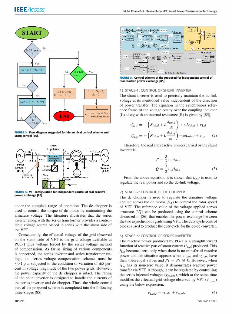
The proposed hierarchical control scheme provides acomplete control over the VFT. Moreover, a series dynamicbraking resistor (SDBR) is also proposed to enhance thefault ride-through (FRT) capability of the VFT system [86].A detailed hierarchical control including all the essentialcontrols is represented in three stages. A practical approach tointerconnect two asynchronous power systems through VFTis discussed below.
The stator of the machine is straightly tied to the PG-1(power grid-1) having frequency f1 and phase angle θ1, andthe rotor is directly connected to PG-2 having frequencyf2 and phase angle θ2. To initiate the asynchronous inter-connection, connect PG-1 to the stator side by closing thecircuit breaker of sending end CBSE meanwhile, the circuitbreaker of receiving end CBRE is open. During this instant,measure the frequency fm and phase angle θm of the voltageinduced across the rotor windings (vm,abc) at CBRE terminals.Measure the frequency f2 and phase angle θ2 of PG-2 voltage(v2,abc) available on the other side of CBRE . At this instant,dc motor drive is used to obtain the matching of frequencyand phase angle. This controlling part is taken care in stage-1and stage-2. Since, once the interconnection is established,power exchange is regulated in stage-3. The control blockdiagram explaining these three corresponding stages of therecommended hierarchical control scheme is shown in Fig. 2.The modification from one step to next step is attained usingthe states S1, S2, S3 as mention in Fig. 2 with predeter-mined sequence along with SDBR protection strategy shownin Fig. 3.
A. STAGES IN HIERARCHICAL CONTROL SCHEME1) STAGE-1: FREQUENCY COORDINATIONAt first, when the stator of VFT is connected across PG-1,the rotor is idle, and CBRE is open, to initiate the frequencymatching step, a command S1 = 1 is released. At this event,
VOLUME 9, 2021 105593

M. M. Khan et al.: Research on VFT: Smart Power Transmission Technology
TABLE 5. US patents granted on VFT system.
TABLE 6. Details of the VFT installation with their basic characteristics.
frequency of the rotor induced voltage fm is to be changedfrom fm = f1 to fm = f2. In order to implement thisdesired frequency transform, the equivalent speed of rotorcorresponding to which the rotor of VFT ought to be directedby dc motor drive is,
N ∗ref =120(f1 − f2)
p(1)
Thus, reference (N ∗ref ) and actual (Nref ) speeds are mea-sured against each other using comparator, and the corre-sponding error, Ea is generated which is further processedto the PI controller to initiate the required armature voltage(V ∗A,1) to feed dc motor. Whenever the average value of sheerspeed error (Ea) falls under 1 rev/min, S1 goes low and S2goes high, which introduces the next phase of the control.
2) STAGE-2: PHASE-ANGLE COORDINATIONIn this stage, phase angle coordinating between (vm,abc) and(v2,abc) is achieved using abc to dq transformation. This abcto dq transformation is applied on the measured rotor inducedvoltages (vm,abc) using phase angle (θ2) of PG-2 voltage(v2,abc), achieved through phase locked loop (PLL), gives thedirect (vm,d ) and quadrature (vm,q) components of the rotorinduced voltages referred to PG-2 voltage phasor. By setting,vm,q = 0, phase angle matching can be achieved. In order toimplement this desired condition, a PI controller is operatedthrough the vm,q to produce the required armature voltage(V ∗A,2). Whenever, the average value of sheer phase angleerror, Eb falls below a pre-set margin, S2 falls low allowingfor the completion of stage-2. Once, the frequency and phaseangle matching is achieved, CBRE is allowed to close to
105594 VOLUME 9, 2021

M. M. Khan et al.: Research on VFT: Smart Power Transmission Technology
TABLE 7. Control strategies to improve the performance of VFT.
interconnect two power grids via VFT. Eventually, S3 goeshigh to initiate the power exchange controller.
3) STAGE-3: POWER EXCHANGE CONTROLThe real power transfer (PVFT ) from PG-1 to PG-2 is allowedto measure at the stator side of the machine and hence,is compared against the reference power (P∗VFT ), and thecorresponding error, Ec is passed over PI controller to causethe required armature voltage (V ∗A,3) and thus, regulates thetorque advanced by the dc motor drive.
B. SDBR-BASED FAULT RIDE-THROUGH CONTROLBoth the SDBR control along with error unveiling is incorpo-rated in the hierarchical control scheme of Fig. 3. In the eventof the fault at the grid, to avoid rotor acceleration, the powerexchange should be controlled at its pre-fault value by forcingS3 = 0 in order to have the corresponding output of the PIcontroller at its pre-fault value. To damp out rotor oscillationsat this event, a command S1 = 1 is again issued via regulatingthe torque of dc motor drive. At the same time, a combina-tion of several resistors in SDBR is inserted to restrict thepropagation of fault from faulted circuit to healthy one. Thiscontrol is implemented with the help of a two-dimensionallookup table which is a function of VFT current and fault
voltage magnitudes. The output of the lookup table definesthe condition of switches Sw1, Sw2, and Sw3 which enablesthe insertion of the proper combination of various resistances.Once the fault is finished, the power exchange controller isrevitalized by releasing the control signals S1 = S2 = 0,S3 = 1 to allow the control of power transfer.
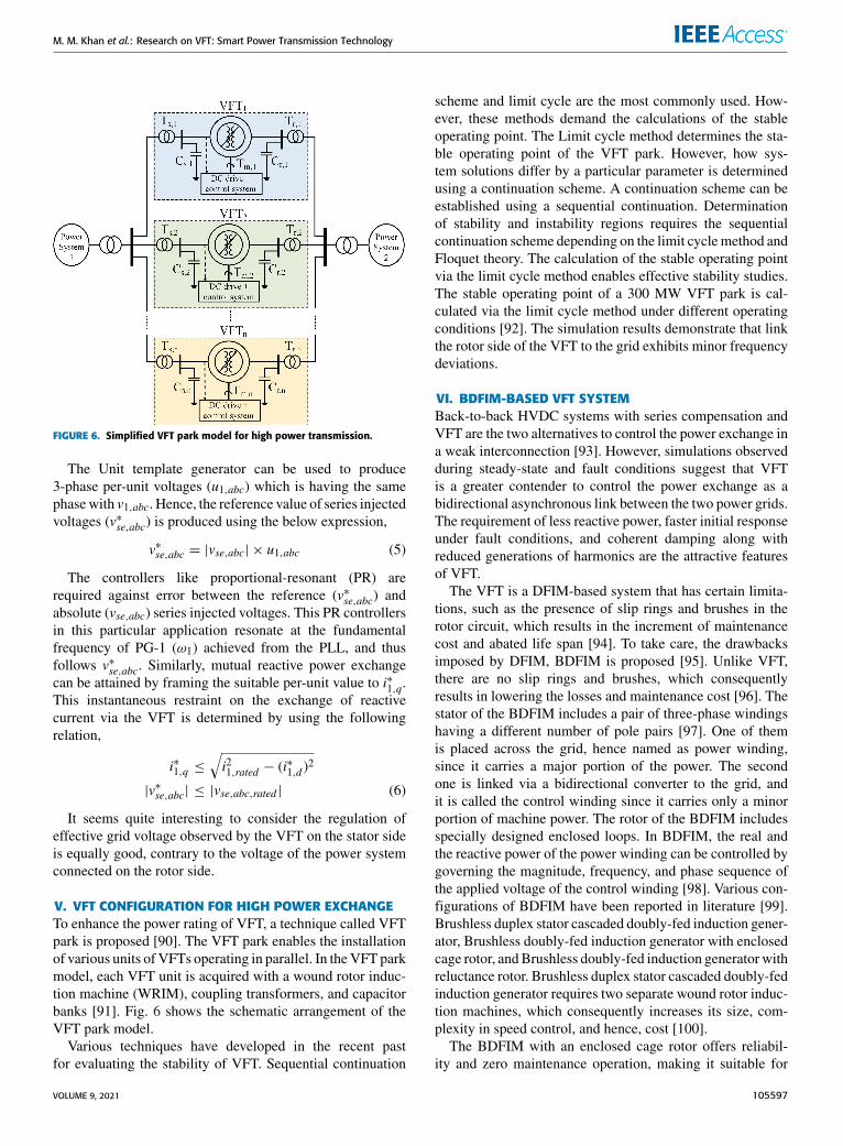
C. DECOUPLED P-Q CONTROLThe reasons for uncontrolled reactive power flow throughthe VFT are (i) variations of the magnitude of the grid volt-ages from their nominal values, (ii) change in active powerflow (magnitude and direction). The reactive power exchangethrough the VFT can be governed by utilizing the series volt-age method of compensation. Hence, a VFT configuration issuggested that incorporates the series voltage method of com-pensation into the traditional VFT system to obtain completecontrol for reactive power exchange as shown in Fig. 4 [85].The traditional thyristor-based dc motor drive is being
replaced by IGBT based dc motor drive in the proposedconfiguration. This dc drive includes a shunt inverter fol-lowing with dc chopper hence, allowing for a commondc-link line. The series inverter is also linked over the iden-tical dc-link line. For the given scheme, the shunt inverterretains the voltage of the dc-link line at a fixed value
VOLUME 9, 2021 105595
M. M. Khan et al.: Research on VFT: Smart Power Transmission Technology
FIGURE 3. Flow diagram suggested for hierarchical control scheme andSDBR control [86].
FIGURE 4. VFT configuration for independent control of real-reactivepower exchange [85].
under the complete range of operation. The dc chopper isused to control the torque of dc motor by maintaining thearmature voltage. The literature illustrates that the seriesinverter along with the series transformer provides a control-lable voltage source placed in series with the stator side ofthe VFT.
Consequently, the effectual voltage of the grid observedon the stator side of VFT is the grid voltage available atPCC-1 plus voltage forced by the series voltage methodof compensation. As far as sizing of various componentsis concerned, the series inverter and series transformer rat-ings, i.e., series voltage compensation scheme, must be≤0.1 p.u. subjected to the condition of variation of ±5 per-cent in voltage magnitude of the two power grids. However,the power capacity of the dc chopper is intact. The ratingof the shunt inverter is designed to handle the currents ofthe series inverter and dc chopper. Thus, the whole controlpart of the proposed scheme is completed into the followingthree-stages [85].
FIGURE 5. Control scheme of the proposed for independent control ofreal-reactive power exchange [85].
1) STAGE-1: CONTROL OF SHUNT INVERTERThe shunt inverter is used to precisely maintain the dc-linkvoltage at its mentioned value independent of the directionof power transfer. The equation in the synchronous refer-ence frame of the voltage equity over the coupling inductor(L) along with an internal resistance (R) is given by [85],
v∗sh,d = −(Rish,d + L
dish,ddt
)+ ωLish,q + v1,d
v∗sh,q = −(Rish,q + L
dish,qdt
)− ωLish,d + v1,q (2)
Therefore, the real and reactive powers carried by the shuntinverter is,
P =32v1,d ish,d
Q =32v1,d ish,q (3)
From the above equation, it is shown that ish,d is used toregulate the real power and so the dc-link voltage.
2) STAGE-2: CONTROL OF DC CHOPPERThe dc chopper is used to regulate the armature voltageapplied across the dc motor (VA) to control the rotor speedof VFT. The reference value of the voltage applied acrossarmature (V ∗A ) can be produced using the control schemediscussed in [86] that enables the power exchange betweenthe two asynchronous grids usingVFT. The duty cycle controlblock is used to produce the duty cycle for the dc-dc converter.
3) STAGE-3: CONTROL OF SERIES INVERTERThe reactive power produced by PG-1 is a straightforwardfunction of reactive part of stator current (i1,q) produced. Thisi1,q becomes zero only when there is no transfer of reactivepower and this situation appears when v1,abc and v2,abc havetheir theoretical values and P1 = P2 ∼= 0. However, wheni1,q has its non-zero value, it demonstrates reactive powertransfer via VFT. Although, it can be regulated by controllingthe series injected voltages (vse,abc), which at the same timemodifies the effectual grid voltage observed by VFT (v′1,abc)using the below expression,
v′1,abc = v1,abc + vse,abc (4)
105596 VOLUME 9, 2021
M. M. Khan et al.: Research on VFT: Smart Power Transmission Technology
FIGURE 6. Simplified VFT park model for high power transmission.
The Unit template generator can be used to produce3-phase per-unit voltages (u1,abc) which is having the samephasewith v1,abc. Hence, the reference value of series injectedvoltages (v∗se,abc) is produced using the below expression,
v∗se,abc = |vse,abc| × u1,abc (5)
The controllers like proportional-resonant (PR) arerequired against error between the reference (v∗se,abc) andabsolute (vse,abc) series injected voltages. This PR controllersin this particular application resonate at the fundamentalfrequency of PG-1 (ω1) achieved from the PLL, and thusfollows v∗se,abc. Similarly, mutual reactive power exchangecan be attained by framing the suitable per-unit value to i∗1,q.This instantaneous restraint on the exchange of reactivecurrent via the VFT is determined by using the followingrelation,
i∗1,q ≤√i21,rated − (i∗1,d )
2
|v∗se,abc| ≤ |vse,abc,rated | (6)
It seems quite interesting to consider the regulation ofeffective grid voltage observed by the VFT on the stator sideis equally good, contrary to the voltage of the power systemconnected on the rotor side.
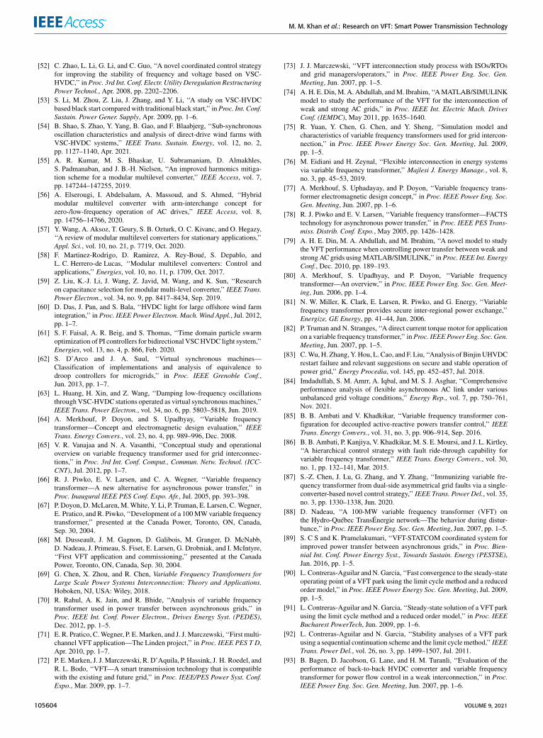
V. VFT CONFIGURATION FOR HIGH POWER EXCHANGETo enhance the power rating of VFT, a technique called VFTpark is proposed [90]. The VFT park enables the installationof various units of VFTs operating in parallel. In theVFT parkmodel, each VFT unit is acquired with a wound rotor induc-tion machine (WRIM), coupling transformers, and capacitorbanks [91]. Fig. 6 shows the schematic arrangement of theVFT park model.
Various techniques have developed in the recent pastfor evaluating the stability of VFT. Sequential continuation
scheme and limit cycle are the most commonly used. How-ever, these methods demand the calculations of the stableoperating point. The Limit cycle method determines the sta-ble operating point of the VFT park. However, how sys-tem solutions differ by a particular parameter is determinedusing a continuation scheme. A continuation scheme can beestablished using a sequential continuation. Determinationof stability and instability regions requires the sequentialcontinuation scheme depending on the limit cyclemethod andFloquet theory. The calculation of the stable operating pointvia the limit cycle method enables effective stability studies.The stable operating point of a 300 MW VFT park is cal-culated via the limit cycle method under different operatingconditions [92]. The simulation results demonstrate that linkthe rotor side of the VFT to the grid exhibits minor frequencydeviations.
VI. BDFIM-BASED VFT SYSTEMBack-to-back HVDC systems with series compensation andVFT are the two alternatives to control the power exchange ina weak interconnection [93]. However, simulations observedduring steady-state and fault conditions suggest that VFTis a greater contender to control the power exchange as abidirectional asynchronous link between the two power grids.The requirement of less reactive power, faster initial responseunder fault conditions, and coherent damping along withreduced generations of harmonics are the attractive featuresof VFT.
The VFT is a DFIM-based system that has certain limita-tions, such as the presence of slip rings and brushes in therotor circuit, which results in the increment of maintenancecost and abated life span [94]. To take care, the drawbacksimposed by DFIM, BDFIM is proposed [95]. Unlike VFT,there are no slip rings and brushes, which consequentlyresults in lowering the losses and maintenance cost [96]. Thestator of the BDFIM includes a pair of three-phase windingshaving a different number of pole pairs [97]. One of themis placed across the grid, hence named as power winding,since it carries a major portion of the power. The secondone is linked via a bidirectional converter to the grid, andit is called the control winding since it carries only a minorportion of machine power. The rotor of the BDFIM includesspecially designed enclosed loops. In BDFIM, the real andthe reactive power of the power winding can be controlled bygoverning the magnitude, frequency, and phase sequence ofthe applied voltage of the control winding [98]. Various con-figurations of BDFIM have been reported in literature [99].Brushless duplex stator cascaded doubly-fed induction gener-ator, Brushless doubly-fed induction generator with enclosedcage rotor, andBrushless doubly-fed induction generator withreluctance rotor. Brushless duplex stator cascaded doubly-fedinduction generator requires two separate wound rotor induc-tion machines, which consequently increases its size, com-plexity in speed control, and hence, cost [100].
The BDFIM with an enclosed cage rotor offers reliabil-ity and zero maintenance operation, making it suitable for
VOLUME 9, 2021 105597

M. M. Khan et al.: Research on VFT: Smart Power Transmission Technology
bulk power transmission. A BDFIM with an enclosed cagerotor offers alternatives against DFIM in various applica-tions such as; adjustable speed drive for big size inductionmachines [101], wind applications [102], and non-contactpower delivery systems [103]. However, it imposes increasedlosses, poor efficiency, and complexity in control due tocomplexity in rotor design. Moreover, a BDFIM, with areluctance rotor, can counter the various drawbacks discussedabove while retaining their benefits. But for weak networks,it may cause increased inverter rating [99]. Moreover, it alsorequires a complex rotor design. The BDFIM can becomean alternative for asynchronous interconnection but requiresspecial machine construction, which increases its complexityand as well as the size of the machine.
VII. DFIM THEORY AND OPERATIONThe DFIM has a pair of three-phase windings accommodatedin the stator and the rotor. Unlike conventional inductionmachines, the rotor circuit is not short-circuited, and the statorand rotor circuit is energized independently through brushesand slip rings arrangement, which enables the star as well asdelta connection for rotor circuit [104]–[106].
The DFIM is very similar to a cage rotor type inductionmachine, but there is a slight difference in construction like;the rotor is larger for DFIM, which also requires routinecare over unavoidable degradation of brushes and slip ringsassembly. The stator includes a set of three-phase windings120 degrees apart in space and having p pairs of poles.As soon as these three-phase windings are energized usinga balanced three-phase voltage source having frequency f1,due to which flux is induced in the stator, which rotates at aconstant speed. This flux also interacts with the rotor circuitand induces an emf across rotor three-phase windings. Thisinduced voltage, along with the externally supplied voltagehaving frequency f2 through brushes, a current is inducedthrough rotor three-phase windings. This induced currentleads to an induced force in the rotor of DFIM. The angularfrequency of the induced current in the rotor circuit is definedas [107]:
ω2 = ω1 − ωm (7)
ω1 is the angular frequency of the voltages and currentsof the stator three-phase windings (rad/s), ω2 is the angularfrequency of the voltages and currents of the rotor three-phasewindings (rad/s), ωm is the angular frequency of the rotor(rad/s), f1 is the electrical frequency of grid-connected onthe stator side (Hz), and f2 is the electrical frequency ofgrid-connected on the rotor side (Hz).
Under normal operating conditions (steady-state),ω2 is theangular frequency of rotor winding voltage and current due toinduction, and the externally supplied voltage across the rotorwinding should also have ω2 angular frequency. Hence, slips is defined as [108]:
s =ω1 − ωm
ω1=ω2
ω1(8)
FIGURE 7. Equivalent circuit of DFIM. (a) Steady-state. (b) Thevenin’sequivalent. (c) Thevenin’s equivalent circuit of VFT based system.
From above expressions:
ω2 = sω1 (9)
Equivalent relation between frequencies is:
f2 = sf1 (10)
If applied frequencies of both sides are identical(f1 = f2), in such a case, slip s becomes unity and rotordoes not move and hence, DFIM appears as a non-rotatingtype transformer [109]. Moreover, the capacity to alter theoffset location of the rotor coil with the stator coil is presentdue to the DC motor drive. This enables the adjustment inimpedance of the transformer. When the applied frequenciesof the two sides are unequal, there exist slip s and the rotorrotates at a speed that is a direct function of the differencebetween the stator and rotor side frequency.
A. ANALYSIS FOR POWER FLOW CONTROLFor calculating active and reactive power transfer via VFT,a steady-state equivalent circuit of VFT based system referredto the stator side is shown in Fig. 7. The terms V, I, R, X,Z, and s represent the voltage, current, resistance, reactance,impedance, and slip, respectively. While subscripts 1 and2 denote the stator and rotor side values, respectively, andsuperscript ′ denotes the quantities of rotor side when referredto stator side. It seems quite interesting to further simplify thecircuit of Fig. 7 (a) by Thevenin’s equivalent circuit at pointsAB [110], [111]. The equation for Thevenin’s Voltage (VTh)is expressed as:
VTh =[
jXmR1 + j(X1 + Xm)
]V1 (11)
The equation for Thevenin’s impedance (ZTh) is expressedas:
ZTh =jXm(R1 + jX1)R1 + j(X1 + Xm)
(12)
105598 VOLUME 9, 2021

M. M. Khan et al.: Research on VFT: Smart Power Transmission Technology
Further simpifying above equations yields:
ZTh =R1X2
m
R21 + (X1 + Xm)2+ j
[Xm[R21+X
21+X1Xm
]R21 + (X1 + Xm)2
](13)
where, the equations for RTh and XTh is:
RTh =R1X2
m
R21 + (X1 + Xm)2(14)
XTh =Xm[R21 + X
21 + X1Xm
]R21 + (X1 + Xm)2
(15)
The current equation at sending end as derived from equiv-alent circuit of Fig. 7 (b) is:
|I1| =|VTh| −
∣∣∣V ′2s ∣∣∣√(RTh +
R′2s
)2+ (XTh + X ′2)
2
(16)
The current equation at receiving end as derived fromequivalent circuit of Fig. 7 (b) is:
∣∣I ′2∣∣ =∣∣∣V ′2s ∣∣∣− |VTh|√(
RTh +R′2s
)2+ (XTh + X ′2)
2
(17)
Now, splitting the terms of voltage source(V ′2s
)and resis-
tance(R′2s
)into following:
V ′2s= V ′2 + V
′
2
(1− ss
)(18)
R′2s= R′2 + R
′
2
(1− ss
)(19)
The terms V ′2(1−ss
)and R′2
(1−ss
)in expression (18)
and (19) together demonstrates the mechanical power devel-oped on the rotor by dc motor. Hence, the equivalent circuitof Fig. 7 (b) is further re-drawn in Fig. 7 (c) to certainlydemonstrate the entire VFT based system containing the dcmotor drive as well. Thus, the active and reactive power atsending end is expressed in equations (20) and (21):
P1 = |V1| |I1| cosφ1 + PD (20)
Q1 = |V1| |I1| sinφ1 (21)
where, φ1 = 6 V1 − 6 I1The active and reactive power obtained at the receiving end
is expressed in equations (22) and (23):
P2 =∣∣V ′2∣∣ ∣∣I ′2∣∣ cosφ2 (22)
Q2 =∣∣V ′2∣∣ ∣∣I ′2∣∣ sinφ2 (23)
where, φ2 = 6 V ′2 − 6 I′
2The mechanical power received by the dc motor drive for
the given system is calculated as [85]:
PD =∣∣V ′2∣∣ ∣∣I ′2∣∣ (1− ss
)cosφ2 −
∣∣I ′2∣∣2 R′2 (1− ss)
(24)
The torque produced by the dc motor drive understeady-state condition is obtained using equation (24):
TD = PD
(pωm
)(25)
where, p is the pairs of pole of the machine
TD =pωm
(1− ss
)[∣∣V ′2∣∣ ∣∣I ′2∣∣ cosφ2 − ∣∣I ′2∣∣2 R′2] (26)
Multiply equation (7) by slip s and further simplificationgive:
ωm
ω2=
(1− ss
)(27)
Substituting equation (27) in equation (26) yields:
TD =pω2
[∣∣V ′2∣∣ ∣∣I ′2∣∣ cosφ2 − ∣∣I ′2∣∣2 R′2] (28)
Also,
TD =psω1
[∣∣V ′2∣∣ ∣∣I ′2∣∣ cosφ2 − ∣∣I ′2∣∣2 R′2] (29)
VIII. SIMULATION STUDIES OF VFT SYSTEMThe two AC power systems (PS-1 and PS-2) having oper-ating frequencies of 60 Hz and 50 Hz, respectively, areinterconnected via the VFT to exchange the power as shownin Fig. 8. It is simulated using PSCAD/EMTDC software.Power System-1 (PS-1) and Power System-2 (PS-2) ratingsare 240 MVA, 230 kV, 60 Hz, and 240 MVA, 230 kV, 50 Hz,respectively. The rating of VFT is 200 MVA, 20 kV. It is con-sidered that the real power flows from PS-1 to PS-2. Hence,PS-1 is the sending end while PS-2 is the receiving end.The PS-1 is connected to the stator side of VFT via circuitbreaker-1 and 230/20 kV transformer, while the PS-2 is tiedto the rotor side of VFT via circuit breaker-2 and 230/20 kVtransformer. A load of 100 MW, 230 kV is also connectedacross the two ends. Overall system response is assessedboth under steady-state and fault conditions keeping torqueconstant at 0.95 pu. The duration of the simulation is 20 s.
A. STEADY-STATE SIMULATIONThe simulation begins with the closing of circuit breaker-1,which energizes the stator side of the VFT at an instant oft = 0.5 s thereby, connecting PS-1. Later, the rotor sideof the VFT is also energized at an instant of t = 1.0 sthereby, connecting PS-2. The simulated results of thethree-phase sending end voltage and current are presentedin Fig. 9 (a) and Fig. 9 (b), respectively. The simulated resultsof the three-phase receiving end (RE) voltage and currentare presented in the Fig. 9 (c) and Fig. 9 (d), respectively.The value of steady-state active power at the sending endand receiving end are 215 MW and 200 MW, respectively,as depicted in Fig. 9 (e). The reactive power exchange for bothsending end and receiving end are demonstrated in Fig. 9 (f).Finally, the variation of active power with respect to torque inthe VFT is illustrated in Fig. 10.
VOLUME 9, 2021 105599

M. M. Khan et al.: Research on VFT: Smart Power Transmission Technology
FIGURE 8. VFT configuration used for steady-state and transient simulations.
FIGURE 9. Steady-state simulation results of power transfer through VFT.(a) Sending end voltage. (b) Sending end current. (c) Receiving endvoltage. (d) Receiving end current. (e) Active power flow at sending endand receiving end. (f) Reactive power flow at sending end and receivingend.
B. TRANSIENT SIMULATIONSIn this section, the performance of VFT system under dif-ferent fault conditions such LG, LL, LLG, and LLLG areevaluated.
1) SINGLE-LINE TO GROUND FAULT ON SENDING ENDThe single-line to ground (LG) fault takes place at PS-1(Fig. 8). The fault duration is 0.05 s (fault evolved at aninstant t = 10.0 s and removed at an instant t = 10.05 s).The simulated results of the three-phase sending end voltageand current are presented in Fig. 11 (a) and Fig. 11 (b),respectively. The simulated results of the three-phase receiv-ing end voltage and current are presented in Fig. 11 (c) andFig. 11 (d), respectively. It is evident from Fig. 11 (b) that thesending end current of the faulty phase overshoots during thefault period and after clearance of the fault settles to its normalvalue. It is also illustrated from Fig. 11 (a) that the sendingend voltage of the faulty phase dips during the fault period
FIGURE 10. Variation of active power with respect to torque in VFT.
and after the clearance of the fault, sending end voltage of thefaulty phase also regain its normal value. Moreover, the LGfault on the sending end has also an impact on the receivingend current (Fig. 11 (d)) as the receiving end current distortsduring the fault, and finally settles to its normal value afterthe removal of the fault. However, the receiving end voltageis completely unaffected. During the LG fault on the sendingend, active power experiences a dip of about 23 MW at thesending end and a comparatively smaller dip of about 20MWat the receiving end as depicted in Fig. 11 (e). Once the fault isover, the sending end’s active power is restored to its normalvalue of 215 MW, while the active power transferred at thereceiving end is also restored to its normal value of 200 MWas depicted in Fig. 11 (e). The reactive power exchangefor both sending end and receiving end are demonstratedin Fig. 11 (f). Therefore, the performance of the system isacceptable during LG fault on the sending end as the healthyside remains practically lesser affected.
2) DOUBLE-LINE FAULT ON SENDING ENDThe double-line (LL) fault takes place at PS-1 (Fig. 8).The fault duration is 0.05 s (fault evolved at an instant t =10.0 s and removed at an instant t = 10.05 s). The simulatedresults of the three-phase sending end voltage and current arepresented in Fig. 12 (a) and Fig. 12 (b), respectively. Thesimulated results of the three-phase receiving end voltageand current are presented in Fig. 12 (c) and Fig. 12 (d),respectively. It is apparent from Fig. 12 (b) that the sendingend current of the faulty phases overshoot during the fault,
105600 VOLUME 9, 2021

M. M. Khan et al.: Research on VFT: Smart Power Transmission Technology
FIGURE 11. Simulation results of power transfer through VFT under LGfault condition. (a) Sending end voltage. (b) Sending end current.(c) Receiving end voltage. (d) Receiving end current. (e) Active power flowat sending end and receiving end. (f) Reactive power flow at sending endand receiving end.
FIGURE 12. Simulation results of power transfer through VFT under LLfault condition. (a) Sending end voltage. (b) Sending end current.(c) Receiving end voltage. (d) Receiving end current. (e) Active power flowat sending end and receiving end. (f) Reactive power flow at sending endand receiving end.
and after clearance of the fault settles to its normal values. It isalso illustrated from Fig. 12 (a) that the sending end voltageof the faulty phases dip during the fault period and afterthe clearance of the fault, sending end voltage of the faultyphases also regain its normal values. Moreover, the LL faulton the sending end has also an impact on the receiving endcurrent (as depicted in Fig. 12 (d)) as the receiving end currentdistorts during the fault, and finally settles to its normal valueafter the removal of the fault. However, the receiving endvoltage is completely unaffected. During the LL fault on thesending end, active power experiences dip of about 29 MW
FIGURE 13. Simulation results of power transfer through VFT under LLGfault condition. (a) Sending end voltage. (b) Sending end current.(c) Receiving end voltage. (d) Receiving end current. (e) Active power flowat sending end and receiving end. (f) Reactive power flow at sending endand receiving end.
at the sending end and about 22 MW at the receiving end asdepicted in Fig. 12 (e). Once the fault is over, the sendingend’s active power is restored to its normal value of 215 MW,while the active power transferred at the receiving end isalso restored to its normal value of 200 MW as depictedin Fig. 12 (e). The reactive power exchange for both sendingend and receiving end are demonstrated in Fig. 12 (f). There-fore, the performance of the system is acceptable during LLfault on the sending end.
3) DOUBLE-LINE TO GROUND FAULT ON SENDING ENDThe double-line to ground (LLG) fault takes place at PS-1(Fig. 8). The fault duration is 0.05 s (fault evolved at aninstant t= 10.0 s and removed at an instant t= 10.05 s). Thesimulated results of the three-phase sending end voltage andcurrent are presented in Fig. 13 (a) and Fig. 13 (b), respec-tively. The simulated results of the three-phase receiving endvoltage and current are presented in Fig. 13 (c) and Fig. 13 (d),respectively. It is evident from Fig. 13 (b) that the sending endcurrent of the faulty phases overshoot during the fault, andafter clearance of the fault settles to its normal values. It isalso illustrated from Fig. 13 (a) that the sending end voltageof the faulty phases dip during the fault period and after theclearance of the fault, sending end voltage of the faulty phasesalso regain its normal values. Moreover, the LLG fault on thesending end has also an impact on the receiving end current(Fig. 13 (d)) as the receiving end current distorts during thefault, and finally settles to its normal value after the removalof the fault. However, the receiving end voltage is completelyunaffected. During the LLG fault on the sending end, activepower experiences dip of about 45MWat the sending end andabout 29 MW at the receiving end as depicted in Fig. 13 (e).
VOLUME 9, 2021 105601

M. M. Khan et al.: Research on VFT: Smart Power Transmission Technology
FIGURE 14. Simulation results of power transfer through VFT under LLLGfault condition. (a) Sending end voltage. (b) Sending end current.(c) Receiving end voltage. (d) Receiving end current. (e) Active power flowat sending end and receiving end. (f) Reactive power flow at sending endand receiving end.
Once the fault is over, the sending end’s active power isrestored to its normal value of 215 MW, while the activepower transferred at the receiving end is also restored to itsnormal value of 200 MW as depicted in Fig. 13 (e). The reac-tive power exchange for both sending end and receiving endare demonstrated in Fig. 13 (f). Therefore, the performanceof the system is acceptable during LLG fault on the sendingend as the healthy side remains practically lesser affected.
4) TRIPLE-LINE TO GROUND FAULT ON SENDING ENDThe triple-line to ground (LLLG) fault takes place at PS-1(Fig. 8). The fault duration is 0.05 s (fault evolved at an instantt = 10.0 s and removed at an instant t = 10.05 s). The simu-lated results of the three-phase sending end voltage and cur-rent are represented in Fig. 14 (a) and Fig. 14 (b), respectively.The simulated results of the three-phase receiving end voltageand current are represented in Fig. 14 (c) and Fig. 14 (d),respectively. It is apparent from Fig. 14 (b) that the sendingend current of the faulty phases overshoot during the fault,and after clearance of the fault settles to its normal values. It isalso illustrated from Fig. 14 (a) that the sending end voltageof the faulty phases dip during the fault period and afterthe clearance of the fault, sending end voltage of the faultyphases also regain its normal values. Moreover, the LLLGfault on the sending end has also an impact on the receivingend current (Fig. 14 (d)) as the receiving end current distortsduring the fault, and finally settles to its normal value afterthe removal of the fault. However, the receiving end voltage iscompletely unaffected. During the LLLG fault on the sendingend, active power experiences dip of about 65 MW at thesending end and about 35MWat the receiving end as depictedin Fig. 14 (e). Once the fault is over, the sending end’s activepower is restored to its normal value of 215 MW, while the
active power transferred at the receiving end is also restoredto its normal value of 200 MW as depicted in Fig. 14 (e). Thereactive power exchange for both sending end and receivingend are demonstrated in Fig. 14 (f). Therefore, the perfor-mance of the system is acceptable during LLLG fault on thesending end as the healthy side remains practically lesseraffected.
IX. CONCLUSIONA detailed review of asynchronous grid interconnection iscarried out to evaluate a broad perspective on the differenttechnologies proposed so far. These technologies are com-pared against each other with their corresponding merits andconstraints. The VFT is found to be a better alternative forpower transfer in a weak AC interconnection over the back-to-back HVDC link.Moreover, a comparison of the VFTwithtraditional back-to-back HVDC link is also carried out whichsuggests VFT a leading innovation over classical technology.Moreover, the VFT suppresses the power oscillations in theinterconnected networks due to its inherent damping ability.Thus, it prevents cascaded tripping, the spread of effects, andgrid failure of the other healthy networks. For high powerexchange, the VFT park model is a better alternative wherethe calculation of the stable operating point via the limitcycle method offers adequate stability studies. To eliminatethe periodic maintenance of slip rings and brushes, a BDFIMbased VFT system is proposed, which retains all the benefitsof the DFIM-based VFT system. Moreover, the performanceof VFT is evaluated using mathematical modeling and simu-lation analysis under both steady-state and various fault con-ditions using PSCAD/EMTDC software. The performance ofthe VFT during steady-state and various fault conditions isfound to be satisfactory. The simulation results prove VFTan acceptable option for asynchronous interconnection. Theperformance of the VFT is satisfactory as the healthy sideremains less affected during fault conditions, and the faultcurrent remains reasonably low. It is expected that this paperwill work as a helpful reference for researchers and designersdealing with asynchronous interconnection.
REFERENCES[1] R. M. Elavarasan, G. Shafiullah, S. Padmanaban, N. M. Kumar,
A. Annam, A. M. Vetrichelvan, L. Mihet-Popa, and J. B. Holm-Nielsen,‘‘A comprehensive review on renewable energy development, challenges,and policies of leading Indian states with an international perspective,’’IEEE Access, vol. 8, pp. 74432–74457, 2020.
[2] M. S. Alam, F. S. Al-Ismail, A. Salem, and M. A. Abido, ‘‘High-levelpenetration of renewable energy sources into grid utility: Challenges andsolutions,’’ IEEE Access, vol. 8, pp. 190277–190299, 2020.
[3] R. Xiong, S. M. Sharkh, H. Li, H. Bai, W. Shen, P. Bai, andX. Zhou, ‘‘IEEE access special section editorial: Advanced energystorage technologies and their applications,’’ IEEE Access, vol. 8,pp. 218685–218693, 2020.
[4] M. Hossain, H. Pota, W. Issa, and M. Hossain, ‘‘Overview of AC micro-grid controls with inverter-interfaced generations,’’ Energies, vol. 10,no. 9, p. 1300, Aug. 2017.
[5] M. Brinkerink, B. Ó. Gallachóir, and P. Deane, ‘‘A comprehensive reviewon the benefits and challenges of global power grids and intercontinentalinterconnectors,’’ Renew. Sustain. Energy Rev., vol. 107, pp. 274–287,Jun. 2019.
105602 VOLUME 9, 2021
M. M. Khan et al.: Research on VFT: Smart Power Transmission Technology
[6] Imdadullah, M. Irshad, M. S. J. Asghar, and S. J. Arif, ‘‘Flexible asyn-chronous AC link for power system network interconnection,’’ in Proc.IEEE Energytech, May 2012, pp. 1–6.
[7] N. R. Friedman, Distributed Energy Resources Interconnection Sys-tems: Technology Review and Research Needs. Accessed: May 15, 2021.[Online]. Available: https://www.osti.gov/biblio/15001120
[8] D. Chen, Y. Xu, and A. Q. Huang, ‘‘Integration of DC microgrids as vir-tual synchronous machines into the AC grid,’’ IEEE Trans. Ind. Electron.,vol. 64, no. 9, pp. 7455–7466, Sep. 2017.
[9] K. R. Padiyar and A. M. Kulkarni, Dynamics and Control of ElectricTransmission and Microgrids. Hoboken, NJ, USA: Wiley, 2019.
[10] H. Zou, S. Mao, Y. Wang, F. Zhang, X. Chen, and L. Cheng, ‘‘A survey ofenergy management in interconnected multi-microgrids,’’ IEEE Access,vol. 7, pp. 72158–72169, 2019.
[11] Imdadullah, H. Rahman, and M. S. J. Asghar, ‘‘A flexible asynchronousAC link for two area power system networks,’’ IEEE Trans. Power Del.,vol. 34, no. 5, pp. 2039–2049, Oct. 2019.
[12] G. Chen and X. Zhou, ‘‘Digital simulation of variable frequency trans-formers for asynchronous interconnection in power system,’’ in Proc.IEEE/PES Transmiss., Distrib. Conf., Expo., Asia Pacific, Aug. 2005,pp. 1–6.
[13] M. S. Thwala, A. F. Nnachi, K. Moloi, and A. O. Akumu, ‘‘The effect ofa phase shift transformer for power flow control,’’ in Proc. Southern Afr.Universities Power Eng. Conf./Robot. Mechtron./Pattern Recognit. Assoc.South Afr. (SAUPEC/RobMech/PRASA), Jan. 2019, pp. 425–430.
[14] A. S. Siddiqui, S. Khan, S. Ahsan, M. I. Khan, and Annamalai, ‘‘Applica-tion of phase shifting transformer in Indian network,’’ in Proc. Int. Conf.Green Technol. (ICGT), Dec. 2012, pp. 186–191.
[15] J. Yuan, L. Chen, and B. Chen, ‘‘The improved sen transformer—A neweffective approach to power transmission control,’’ in Proc. IEEE EnergyConvers. Congr. Expo. (ECCE), Sep. 2014, pp. 724–729.
[16] K. K. Sen and M. L. Sen, ‘‘Introducing the family of ‘Sen’ transformers:A set of power flow controlling transformers,’’ IEEE Trans. Power Del.,vol. 18, no. 1, pp. 149–157, Jan. 2003.
[17] A. O. Ba, T. Peng, and S. Lefebvre, ‘‘Rotary power-flow controller fordynamic performance evaluation—Part I: RPFC modeling,’’ IEEE Trans.Power Del., vol. 24, no. 3, pp. 1406–1416, Jul. 2009.
[18] Z. Tan, C. Zhang, and Q. Jiang, ‘‘Research on characteristics and powerflow control strategy of rotary power flow controller,’’ in Proc. 5th Int.Youth Conf. Energy (IYCE), May 2015, pp. 1–8.
[19] Imdadullah, S. M. Amrr, M. S. J. Asghar, I. Ashraf, and M. Meraj,‘‘A comprehensive review of power flow controllers in interconnectedpower system networks,’’ IEEE Access, vol. 8, pp. 18036–18063, 2020.
[20] K. K. Sen and M. L. Sen, ‘‘Modeling of the sen transformer using anelectromagnetic transients program,’’ HOW2POWER TODAY, pp. 1–29,Mar. 2018.
[21] J. Yuan, L. Liu, W. Fei, L. Chen, B. Chen, and B. Chen, ‘‘Hybrid elec-tromagnetic unified power flow controller: A novel flexible and effectiveapproach to control power flow,’’ IEEE Trans. Power Del., vol. 33, no. 5,pp. 2061–2069, Oct. 2018.
[22] Z. Chunpeng, J. Qirong, W. Yingdong, H. Chao, C. Yan, and S. Dan,‘‘A series voltage compensator based on thyristor-controlled trans-former,’’ in Proc. IEEE PES Asia–Pacific Power Energy Eng. Conf.(APPEEC), Nov. 2015, pp. 1–5.
[23] D. Gao, Q. Lu, and J. Luo, ‘‘A new scheme for on-load tap-changer oftransformers,’’ in Proc. Int. Conf. Power Syst. Technol., vol. 2, 2002,pp. 1016–1020.
[24] A. Kramer and J. Ruff, ‘‘Transformers for phase angle regulation con-sidering the selection of on-load tap-changers,’’ IEEE Trans. Power Del.,vol. 13, no. 2, pp. 518–525, Apr. 1998.
[25] J. Verboomen, D. Van Hertem, P. H. Schavemaker, W. L. Kling, andR. Belmans, ‘‘Phase shifting transformers: Principles and applications,’’in Proc. Int. Conf. Future Power Syst., 2005, pp. 1–6.
[26] K. Sen andM. L. Sen, ‘‘Introducing the family of SEN transformers: A setof power flow controlling transformers,’’ IEEE Power Eng. Rev., vol. 22,no. 7, p. 63, Jul. 2002.
[27] K. K. Sen and M. L. Sen, ‘‘Comparison of the ‘Sen’ transformer with theunified power flow controller,’’ IEEE Trans. Power Del., vol. 18, no. 4,pp. 1523–1533, Oct. 2003.
[28] K. K. Sen and M. L. Sen, ‘‘Comparison of operational characteristicsbetween a sen transformer and a phase angle regulator,’’ in Proc. IEEEPower Energy Soc. Gen. Meeting (PESGM), Jul. 2016, pp. 1–5.
[29] H. Fujita, S. Hara, K. J. Piwko, E. R. Pratico, and J. Sanchez-Gasca,‘‘Simulator model of rotary power flow controller,’’ in Proc. Power Eng.Soc. Summer Meeting. Conf., vol. 3, 2001, pp. 1794–1797.
[30] D. Divan and J. Sastry, ‘‘Controllable network transformers,’’ in Proc.IEEE Power Electron. Specialists Conf., Jun. 2008, pp. 2340–2345.
[31] D. Das, D. M. Divan, and R. G. Harley, ‘‘Power flow control in networksusing controllable network transformers,’’ IEEE Trans. Power Electron.,vol. 25, no. 7, pp. 1753–1760, Jul. 2010.
[32] H. Chen, A. R. Iyer, R. G. Harley, and D. Divan, ‘‘Dynamic grid powerrouting using controllable network transformers (CNTs) with decou-pled closed-loop controller,’’ IEEE Trans. Ind. Appl., vol. 51, no. 3,pp. 2361–2372, May/Jun. 2015.
[33] Imdadullah and M. S. J. Asghar, ‘‘Bidirectional power transmission andgrid interconnections using flexible asynchronous AC transmission link,’’in Proc. IEEE Int. Conf. Comput., Power Commun. Technol., Sep. 2019,pp. 224–229.
[34] K. Padiyar, FACTS Controllers in Power Transmission and Distribution.Tunbridge Wells, U.K.: Anshan, 2009.
[35] F. H. Gandoman, A. Ahmadi, A. M. Sharaf, P. Siano, J. Pou, B. Hredzak,and V. G. Agelidis, ‘‘Review of FACTS technologies and applications forpower quality in smart grids with renewable energy systems,’’ Renew.Sustain. Energy Rev., vol. 82, pp. 502–514, Feb. 2018.
[36] L. Gyugyi, C. D. Schauder, and K. K. Sen, ‘‘Static synchronous seriescompensator: A solid-state approach to the series compensation of trans-mission lines,’’ IEEE Trans. Power Del., vol. 12, no. 1, pp. 406–417,Jan. 1997.
[37] A. H. Norouzi and A. M. Sharaf, ‘‘Two control schemes to enhance thedynamic performance of the STATCOM and SSSC,’’ IEEE Trans. PowerDel., vol. 20, no. 1, pp. 435–442, Jan. 2005.
[38] R. M. Mathur and R. K. Varma, Thyristor–Based FACTS Controllers forElectrical Transmission Systems. Hoboken, NJ, USA: Wiley, 2002.
[39] P. Singh and R. Tiwari, ‘‘STATCOM model using holomorphic embed-ding,’’ IEEE Access, vol. 7, pp. 33075–33086, 2019.
[40] L. Gyugyi, C. D. Schauder, S. L. Williams, T. R. Rietman,D. R. Torgerson, and A. Edris, ‘‘The unified power flow controller:A new approach to power transmission control,’’ IEEE Trans. PowerDel., vol. 10, no. 2, pp. 1085–1097, Apr. 1995.
[41] Y. Liu, S. Yang, and F. Z. Peng, ‘‘Operation and analysis of an improvedtransformerless unified power flow controller,’’ in Proc. IEEE Appl.Power Electron. Conf. Expo. (APEC), Mar. 2016, pp. 959–965.
[42] T. V. Charan and A. M. Parimi, ‘‘Comparision of interline power flowcontroller with line reactor and SSSC in a 400kV transmission line,’’ inProc. 3rd Int. Conf. Converg. Technol. (I CT), Apr. 2018, pp. 1–6.
[43] R. Vasquez-Arnez and F. Moreira, ‘‘Main advantages and limitationsof the interline power flow controller: A steady-state analysis,’’ System,vol. 1, no. 14, p. Z11, 2008.
[44] M. Ebeed, S. Kamel, and F. Jurado, ‘‘Determination of IPFC operatingconstraints in power flow analysis,’’ Int. J. Electr. Power Energy Syst.,vol. 81, pp. 299–307, Oct. 2016.
[45] M. R. Magara, B. R. Tiwarib, R. Sharma, S. Adhikari, and S. Shresthae,‘‘MATLAB simulation of variable frequency transformer for power trans-fer in-between power system networks,’’ in Proc. IOE Graduate Conf.,2019, pp. 99–105.
[46] L. Wang, S.-R. Jan, C.-N. Li, H.-W. Li, Y.-H. Huang, and Y.-T. Chen,‘‘Analysis of an integrated offshore wind farm and seashore wave farmfed to a power grid through a variable frequency transformer,’’ in Proc.IEEE Power Energy Soc. Gen. Meeting, Jul. 2011, pp. 1–7.
[47] F. I. Bakhsh, M. Irshad, and M. S. J. Asghar, ‘‘Modeling and simulationof variable frequency transformer for power transfer in-between powersystem networks,’’ in Proc. India Int. Conf. Power Electron. (IICPE),Jan. 2011, pp. 1–7.
[48] H. Wang and M. A. Redfern, ‘‘The advantages and disadvantages ofusing HVDC to interconnect AC networks,’’ in Proc. 45th IEEE Int.Universities Power Eng. Conf., Aug. 2010, pp. 1–5.
[49] C. Guo and C. Zhao, ‘‘Supply of an entirely passive AC network througha double-infeed HVDC system,’’ IEEE Trans. Power Electron., vol. 25,no. 11, pp. 2835–2841, Nov. 2010.
[50] J.-G. Lee, U. A. Khan, H.-Y. Lee, S.-W. Lim, and B.-W. Lee, ‘‘Mitigationof commutation failures in LCC–HVDC systems based on supercon-ducting fault current limiters,’’ Phys. C, Supercond. Appl., vol. 530,pp. 160–163, Nov. 2016.
[51] A. M. Vural, ‘‘Contribution of high voltage direct current transmissionsystems to inter-area oscillation damping: A review,’’ Renew. Sustain.Energy Rev., vol. 57, pp. 892–915, May 2016.
VOLUME 9, 2021 105603
M. M. Khan et al.: Research on VFT: Smart Power Transmission Technology
[52] C. Zhao, L. Li, G. Li, and C. Guo, ‘‘A novel coordinated control strategyfor improving the stability of frequency and voltage based on VSC-HVDC,’’ in Proc. 3rd Int. Conf. Electr. Utility Deregulation RestructuringPower Technol., Apr. 2008, pp. 2202–2206.
[53] S. Li, M. Zhou, Z. Liu, J. Zhang, and Y. Li, ‘‘A study on VSC-HVDCbased black start comparedwith traditional black start,’’ inProc. Int. Conf.Sustain. Power Gener. Supply, Apr. 2009, pp. 1–6.
[54] B. Shao, S. Zhao, Y. Yang, B. Gao, and F. Blaabjerg, ‘‘Sub-synchronousoscillation characteristics and analysis of direct-drive wind farms withVSC-HVDC systems,’’ IEEE Trans. Sustain. Energy, vol. 12, no. 2,pp. 1127–1140, Apr. 2021.
[55] A. R. Kumar, M. S. Bhaskar, U. Subramaniam, D. Almakhles,S. Padmanaban, and J. B.-H. Nielsen, ‘‘An improved harmonics mitiga-tion scheme for a modular multilevel converter,’’ IEEE Access, vol. 7,pp. 147244–147255, 2019.
[56] A. Elserougi, I. Abdelsalam, A. Massoud, and S. Ahmed, ‘‘Hybridmodular multilevel converter with arm-interchange concept forzero-/low-frequency operation of AC drives,’’ IEEE Access, vol. 8,pp. 14756–14766, 2020.
[57] Y. Wang, A. Aksoz, T. Geury, S. B. Ozturk, O. C. Kivanc, and O. Hegazy,‘‘A review of modular multilevel converters for stationary applications,’’Appl. Sci., vol. 10, no. 21, p. 7719, Oct. 2020.
[58] F. Martinez-Rodrigo, D. Ramirez, A. Rey-Boué, S. Depablo, andL. C. Herrero-de Lucas, ‘‘Modular multilevel converters: Control andapplications,’’ Energies, vol. 10, no. 11, p. 1709, Oct. 2017.
[59] Z. Liu, K.-J. Li, J. Wang, Z. Javid, M. Wang, and K. Sun, ‘‘Researchon capacitance selection for modular multi-level converter,’’ IEEE Trans.Power Electron., vol. 34, no. 9, pp. 8417–8434, Sep. 2019.
[60] D. Das, J. Pan, and S. Bala, ‘‘HVDC light for large offshore wind farmintegration,’’ in Proc. IEEE Power Electron. Mach. Wind Appl., Jul. 2012,pp. 1–7.
[61] S. F. Faisal, A. R. Beig, and S. Thomas, ‘‘Time domain particle swarmoptimization of PI controllers for bidirectional VSCHVDC light system,’’Energies, vol. 13, no. 4, p. 866, Feb. 2020.
[62] S. D’Arco and J. A. Suul, ‘‘Virtual synchronous machines—Classification of implementations and analysis of equivalence todroop controllers for microgrids,’’ in Proc. IEEE Grenoble Conf.,Jun. 2013, pp. 1–7.
[63] L. Huang, H. Xin, and Z. Wang, ‘‘Damping low-frequency oscillationsthroughVSC-HVDC stations operated as virtual synchronousmachines,’’IEEE Trans. Power Electron., vol. 34, no. 6, pp. 5803–5818, Jun. 2019.
[64] A. Merkhouf, P. Doyon, and S. Upadhyay, ‘‘Variable frequencytransformer—Concept and electromagnetic design evaluation,’’ IEEETrans. Energy Convers., vol. 23, no. 4, pp. 989–996, Dec. 2008.
[65] V. R. Vanajaa and N. A. Vasanthi, ‘‘Conceptual study and operationaloverview on variable frequency transformer used for grid interconnec-tions,’’ in Proc. 3rd Int. Conf. Comput., Commun. Netw. Technol. (ICC-CNT), Jul. 2012, pp. 1–7.
[66] R. J. Piwko, E. V. Larsen, and C. A. Wegner, ‘‘Variable frequencytransformer—A new alternative for asynchronous power transfer,’’ inProc. Inaugural IEEE PES Conf. Expo. Afr., Jul. 2005, pp. 393–398.
[67] P. Doyon, D.McLaren,M.White, Y. Li, P. Truman, E. Larsen, C. Wegner,E. Pratico, and R. Piwko, ‘‘Development of a 100MWvariable frequencytransformer,’’ presented at the Canada Power, Toronto, ON, Canada,Sep. 30, 2004.
[68] M. Dusseault, J. M. Gagnon, D. Galibois, M. Granger, D. McNabb,D. Nadeau, J. Primeau, S. Fiset, E. Larsen, G. Drobniak, and I. McIntyre,‘‘First VFT application and commissioning,’’ presented at the CanadaPower, Toronto, ON, Canada, Sep. 30, 2004.
[69] G. Chen, X. Zhou, and R. Chen, Variable Frequency Transformers forLarge Scale Power Systems Interconnection: Theory and Applications.Hoboken, NJ, USA: Wiley, 2018.
[70] R. Rahul, A. K. Jain, and R. Bhide, ‘‘Analysis of variable frequencytransformer used in power transfer between asynchronous grids,’’ inProc. IEEE Int. Conf. Power Electron., Drives Energy Syst. (PEDES),Dec. 2012, pp. 1–5.
[71] E. R. Pratico, C.Wegner, P. E.Marken, and J. J.Marczewski, ‘‘First multi-channel VFT application—The Linden project,’’ in Proc. IEEE PES T D,Apr. 2010, pp. 1–7.
[72] P. E.Marken, J. J.Marczewski, R. D’Aquila, P. Hassink, J. H. Roedel, andR. L. Bodo, ‘‘VFT—A smart transmission technology that is compatiblewith the existing and future grid,’’ in Proc. IEEE/PES Power Syst. Conf.Expo., Mar. 2009, pp. 1–7.
[73] J. J. Marczewski, ‘‘VFT interconnection study process with ISOs/RTOsand grid managers/operators,’’ in Proc. IEEE Power Eng. Soc. Gen.Meeting, Jun. 2007, pp. 1–5.
[74] A.H. E. Din,M.A.Abdullah, andM. Ibrahim, ‘‘AMATLAB/SIMULINKmodel to study the performance of the VFT for the interconnection ofweak and strong AC grids,’’ in Proc. IEEE Int. Electric Mach. DrivesConf. (IEMDC), May 2011, pp. 1635–1640.
[75] R. Yuan, Y. Chen, G. Chen, and Y. Sheng, ‘‘Simulation model andcharacteristics of variable frequency transformers used for grid intercon-nection,’’ in Proc. IEEE Power Energy Soc. Gen. Meeting, Jul. 2009,pp. 1–5.
[76] M. Eidiani and H. Zeynal, ‘‘Flexible interconnection in energy systemsvia variable frequency transformer,’’ Majlesi J. Energy Manage., vol. 8,no. 3, pp. 45–53, 2019.
[77] A. Merkhouf, S. Uphadayay, and P. Doyon, ‘‘Variable frequency trans-former electromagnetic design concept,’’ in Proc. IEEE Power Eng. Soc.Gen. Meeting, Jun. 2007, pp. 1–6.
[78] R. J. Piwko and E. V. Larsen, ‘‘Variable frequency transformer—FACTStechnology for asynchronous power transfer,’’ in Proc. IEEE PES Trans-miss. Distrib. Conf. Expo., May 2005, pp. 1426–1428.
[79] A. H. E. Din, M. A. Abdullah, and M. Ibrahim, ‘‘A novel model to studythe VFT performance when controlling power transfer between weak andstrongAC grids usingMATLAB/SIMULINK,’’ inProc. IEEE Int. EnergyConf., Dec. 2010, pp. 189–193.
[80] A. Merkhouf, S. Upadhyay, and P. Doyon, ‘‘Variable frequencytransformer—An overview,’’ in Proc. IEEE Power Eng. Soc. Gen. Meet-ing, Jun. 2006, pp. 1–4.
[81] N. W. Miller, K. Clark, E. Larsen, R. Piwko, and G. Energy, ‘‘Variablefrequency transformer provides secure inter-regional power exchange,’’Energize, GE Energy, pp. 41–44, Jun. 2006.
[82] P. Truman and N. Stranges, ‘‘A direct current torque motor for applicationon a variable frequency transformer,’’ inProc. IEEEPower Eng. Soc. Gen.Meeting, Jun. 2007, pp. 1–5.
[83] C.Wu, H. Zhang, Y. Hou, L. Cao, and F. Liu, ‘‘Analysis of Binjin UHVDCrestart failure and relevant suggestions on secure and stable operation ofpower grid,’’ Energy Procedia, vol. 145, pp. 452–457, Jul. 2018.
[84] Imdadullah, S. M. Amrr, A. Iqbal, and M. S. J. Asghar, ‘‘Comprehensiveperformance analysis of flexible asynchronous AC link under variousunbalanced grid voltage conditions,’’ Energy Rep., vol. 7, pp. 750–761,Nov. 2021.
[85] B. B. Ambati and V. Khadkikar, ‘‘Variable frequency transformer con-figuration for decoupled active-reactive powers transfer control,’’ IEEETrans. Energy Convers., vol. 31, no. 3, pp. 906–914, Sep. 2016.
[86] B. B. Ambati, P. Kanjiya, V. Khadkikar, M. S. E.Moursi, and J. L. Kirtley,‘‘A hierarchical control strategy with fault ride-through capability forvariable frequency transformer,’’ IEEE Trans. Energy Convers., vol. 30,no. 1, pp. 132–141, Mar. 2015.
[87] S.-Z. Chen, J. Lu, G. Zhang, and Y. Zhang, ‘‘Immunizing variable fre-quency transformer from dual-side asymmetrical grid faults via a single-converter-based novel control strategy,’’ IEEE Trans. Power Del., vol. 35,no. 3, pp. 1330–1338, Jun. 2020.
[88] D. Nadeau, ‘‘A 100-MW variable frequency transformer (VFT) onthe Hydro-Québec TransÉnergie network—The behavior during distur-bance,’’ in Proc. IEEE Power Eng. Soc. Gen. Meeting, Jun. 2007, pp. 1–5.
[89] S. C S and K. Pramelakumari, ‘‘VFT-STATCOM coordinated system forimproved power transfer between asynchronous grids,’’ in Proc. Bien-nial Int. Conf. Power Energy Syst., Towards Sustain. Energy (PESTSE),Jan. 2016, pp. 1–5.
[90] L. Contreras-Aguilar andN. Garcia, ‘‘Fast convergence to the steady-stateoperating point of a VFT park using the limit cycle method and a reducedorder model,’’ in Proc. IEEE Power Energy Soc. Gen. Meeting, Jul. 2009,pp. 1–5.
[91] L. Contreras-Aguilar and N. Garcia, ‘‘Steady-state solution of a VFT parkusing the limit cycle method and a reduced order model,’’ in Proc. IEEEBucharest PowerTech, Jun. 2009, pp. 1–6.
[92] L. Contreras-Aguilar and N. Garcia, ‘‘Stability analyses of a VFT parkusing a sequential continuation scheme and the limit cyclemethod,’’ IEEETrans. Power Del., vol. 26, no. 3, pp. 1499–1507, Jul. 2011.
[93] B. Bagen, D. Jacobson, G. Lane, and H. M. Turanli, ‘‘Evaluation of theperformance of back-to-back HVDC converter and variable frequencytransformer for power flow control in a weak interconnection,’’ in Proc.IEEE Power Eng. Soc. Gen. Meeting, Jun. 2007, pp. 1–6.
105604 VOLUME 9, 2021
M. M. Khan et al.: Research on VFT: Smart Power Transmission Technology
[94] P. Ledesma and J. Usaola, ‘‘Doubly fed induction generator model fortransient stability analysis,’’ IEEE Trans. Energy Convers., vol. 20, no. 2,pp. 388–397, Jun. 2005.
[95] A. S. Abdel-Khalik, A. Elserougi, S. Ahmed, and A. Massoud, ‘‘Brush-less doubly fed induction machine as a variable frequency transformer,’’in Proc. 6th IET Int. Conf. Power Electron., Mach. Drives (PEMD), 2012,pp. 1–6.
[96] A. Zhang, X. Wang, W. Jia, and Y. Ma, ‘‘Indirect stator-quantities controlfor the brushless doubly fed induction machine,’’ IEEE Trans. PowerElectron., vol. 29, no. 3, pp. 1392–1401, Mar. 2014.
[97] R. Resmi, V. Vanitha, T. Nambiar, and S. K. Kottayil, ‘‘Design and imple-mentation of brushless doubly fed induction machine with new statorwinding configuration,’’Wind Eng., vol. 45, no. 1, pp. 11–23, Feb. 2021.
[98] S. O. Madbouly, H. F. Soliman, and A. M. Sharaf, ‘‘A new coordinatedinter-coupled vector control of brushless doubly fed wind driven induc-tion generator,’’ IJPEGT J., no. 2, pp. 1–8, 2011.
[99] M. I. Abdelkader, A. K. Abdelsalam, and A. A. Hossam, ‘‘Asynchronousgrid interconnection using brushless doubly fed induction machines:Assessment on various configurations,’’ inProc. 16th Int. Power Electron.Motion Control Conf. Expo., Sep. 2014, pp. 406–412.
[100] M. A. M. Abdulla, ‘‘New system for power transfer between two asyn-chronous grids using twin stator induction machine,’’ in Proc. IEEE Int.Electr. Mach. Drives Conf. (IEMDC), May 2011, pp. 1658–1663.
[101] S. Shao, E. Abdi, and R. Mcmahon, ‘‘Low-cost variable speed drivebased on a brushless doubly-fed motor and a fractional unidirectionalconverter,’’ IEEE Trans. Ind. Electron., vol. 59, no. 1, pp. 317–325,Jan. 2012.
[102] Q. Wang, X. Chen, and Y. Ji, ‘‘Control for maximal wind energy tracingin matrix converter AC excited brushless doubly-fed wind power gener-ation system,’’ in Proc. 32nd Annu. Conf. IEEE Ind. Electron. (IECON),Nov. 2006, pp. 718–723.
[103] A. S. Abdel-Khalik, M. I. Masoud, B. W. Williams, A. L. Mohamadein,and M. M. Ahmed, ‘‘Steady-state performance and stability analysis ofmixed pole machines with electromechanical torque and rotor electricpower to a shaft-mounted electrical load,’’ IEEE Trans. Ind. Electron.,vol. 57, no. 1, pp. 22–34, Jan. 2010.
[104] H. Akagi and H. Sato, ‘‘Control and performance of a doubly-fed induc-tionmachine intended for a flywheel energy storage system,’’ IEEETrans.Power Electron., vol. 17, no. 1, pp. 109–116, Jan. 2002.
[105] M. A. Poller, ‘‘Doubly-fed induction machine models for stability assess-ment of wind farms,’’ in Proc. IEEE Bologna Power Tech Conf., vol. 3,Jun. 2003, pp. 1–6.
[106] L. Xu and W. Cheng, ‘‘Torque and reactive power control of a doublyfed induction machine by position sensorless scheme,’’ IEEE Trans. Ind.Appl., vol. 31, no. 3, pp. 636–642, May/Jun. 1995.
[107] G. Abad, J. Lopez, M. Rodriguez, L. Marroyo, and G. Iwanski, DoublyFed Induction Machine: Modeling and Control for Wind Energy Genera-tion, vol. 85. Hoboken, NJ, USA: Wiley, 2011.
[108] H. Abu-Rub, M. Malinowski, and K. Al-Haddad, Power Electronics forRenewable Energy Systems, Transportation and Industrial Applications.Hoboken, NJ, USA: Wiley, 2014.
[109] B. C. Raczkowski and P. W. Sauer, ‘‘Doubly-fed induction machineanalysis for power flow control,’’ in Proc. Electr. Insul. Conf. Electr.Manuf. Expo., 2005, pp. 454–459.
[110] S. Chapman, Electric Machinery Fundamentals. New York, NY, USA:McGraw-Hill, 2005.
[111] Imdadullah and M. S. J. Asghar, ‘‘Performance evaluation of doubly fedinduction machine used in flexible asynchronous AC link for power flowcontrol applications,’’ in Proc. Int. Conf. Electr., Electron. Comput. Eng.(UPCON), Nov. 2019, pp. 1–6.
MOHD MOHSIN KHAN received the B.Tech.degree in electrical engineering from the Depart-ment of Electrical Engineering, Zakir Husain Col-lege of Engineering and Technology (ZHCET),Aligarh Muslim University (AMU), Aligarh,India, in 2018, where he is currently pursuing theM.Tech. degree in power system and drives. Hisresearch interests include power systems, and vari-able frequency transformer and control.
IMDADULLAH (Senior Member, IEEE) receivedthe bachelor’s degree in electrical engineering,and the master’s and Ph.D. degrees in power sys-tems and drives from the Department of ElectricalEngineering, Zakir Hussain College of Engineer-ing and Technology, Aligarh Muslim University(AMU), Aligarh, India, in 2003, 2006, and 2020,respectively. He has about 14 years of teachingand research experience. Since December 2007,he has been working as an Assistant Professor with
the Electrical Engineering Section, University Polytechnic, AMU. He haspublished several research articles in international journals/conference pro-ceedings, including articles in IEEETRANSACTIONS/journals. He holds a patenton the FASAL system, ‘‘A Concept of Flexible Asynchronous AC Link.’’His research interests include renewable energy, power systems, drives,instrumentation, and measurement.
JAMEL NEBHEN received the M.Sc. degreein microelectronics from the National Engi-neering School of Sfax, Tunisia, in 2007,and the Ph.D. degree in microelectronics fromAix-Marseille University, France, in 2012. From2012 to 2018, he worked as a PostdoctoralResearcher with the LIRMM-Laboratory Mont-pellier, IM2NP-Laboratory Marseille, ISEP Paris,LE2I-Laboratory Dijon, Laboratory-Sticc Tele-com Bretagne Brest, and IEMN-Laboratory Lille,
France. Since 2019, he has been an Assistant Professor with Prince SattamBin Abdulaziz University, Alkharj, Saudi Arabia. His research interestsinclude design of analog and RF integrated circuits, the IoT, biomedicalcircuit, wireless communication systems, and sensors instrumentation.
HAFIZUR RAHMAN received the B.Sc. (Engg),M.Sc. (Engg.), and Ph.D. degrees in electri-cal engineering from Aligarh Muslim Univer-sity (AMU), Aligarh, India. From 1980 to 1985,he worked as an Electrical Engineer in India andabroad. Since 1985, he has been the Faculty ofAMU, where he is currently a Professor with theElectrical Engineering Department, Z. H. Collegeof Engineering and Technology. He has publishedseveral research articles in international journals
and conferences. He was also engaged in a research project on ‘‘Simultane-ous AC–DC Power Transmission’’ sponsored by AICTE, New Delhi, India.His research interests include HVDC, FACTS, and composite ac–dc powersystems. He is a Life Member of the Indian Society for Technical Education,New Delhi.
VOLUME 9, 2021 105605