reservoir protection zones
TRANSCRIPT
REPUBLIC
OF CYPRUS
MINISTRY OF AGRICULTURE, NATURAL RESOURCES AND ENVIRONMENT
WATER DEVELOPMENT DEPARTMENT
NICOSIA
RRReeessseeerrrvvvoooiiirrr PPPrrrooottteeeccctttiiiooonnn ZZZooonnneeesss MMMeeettthhhoooddd fffooorrr dddeeettteeerrrmmmiiinnniiinnnggg ttthhheee zzzooonnneeesss
FFFiiinnnaaalll rrreeepppooorrrttt --- pppaaarrrttt 333///333
November 2010
REPUBLIC OF CYPRUS - MINISTRY OF AGRICULTURE, NATURAL RESOURCES AND ENVIRONMENT - WATER DEVELOPMENT DEPARTMENT - NICOSIA Reservoir Protection Zones - Method for determining the zones – November 2010
Page 2 of 50
NOTICE The documents produced within the project “Reservoir Protection Zones for the reservoirs that are used for drinking water purposes” for the Water Development Department (WDD) of the Ministry of Agriculture, Natural Resources and Environment, are divided into three separate documents :
1. KOURIS Reservoir Protection Ordinance 2. KOURIS Reservoir Protection - Action plan and Recommendations for protection ordinance
enforcement 3. Reservoir Protection Zones - Method for determining the zones
The Recommendations should be published by WDD as Action plan, and, the final Ordinance should make reference to the Recommendations, so as they gain in regulative power. Authors Dr. Yves GOUISSET Head of the Reporting, Evaluation and Pressures service Rhone and Mediterranean district Rhône-Alpes Regional Directorate Ministry of Ecology, Energy, Sustainable Development and the Sea Kostas ARISTEIDOU (for ANNEX – CPZ: GIS proposed application) Hydrologist Division of Hydrology & Hydrogeology Water Development Department Ministry of Agriculture, Natural resources and Environment Version : Final File name : cyprus reservoirs protection zones - methods v8a.doc Date : November 2010
REPUBLIC OF CYPRUS - MINISTRY OF AGRICULTURE, NATURAL RESOURCES AND ENVIRONMENT - WATER DEVELOPMENT DEPARTMENT - NICOSIA Reservoir Protection Zones - Method for determining the zones – November 2010
Page 3 of 50
Table of contents 1. INTRODUCTION ................................................................................................................................... 5
1.1. CONTEXT OF THE MISSION ................................................................................................................. 5
1.2. GENERAL PROGRAM OF THE MISSION ................................................................................................ 5
1.3. ACKNOWLEDGEMENTS ...................................................................................................................... 5
2. SUMMARY OF GENERAL PRINCIPLES ......................................................................................... 6
2.1. GENERAL CONSIDERATIONS FOR RESERVOIR PROTECTION ............................................................... 6
2.2. FOUR RESERVOIR PROTECTION ZONES ............................................................................................... 6
2.2.1. The Immediate Protection Zone (IPZ) ....................................................................................... 6
2.2.2. The Close Protection Zone (CPZ) ............................................................................................. 6
2.2.3. The Distant Protection Zone (DPZ) .......................................................................................... 7
2.2.4. The Riparian Protection Strip ................................................................................................... 7
3. METHOD FOR ESTABLISHING THE IMMEDIATE PROTECTION ZO NE (IPZ) ................... 8
3.1. GOAL OF THE IPZ ............................................................................................................................... 8
3.2. DELINEATION OF THE IPZ .................................................................................................................. 8
3.3. PHYSICAL PROTECTION ...................................................................................................................... 9
3.3.1. Protection of installation, building and equipments .................................................................. 9
3.3.2. Protection of the immediate surroundings of the dam and intake ............................................. 9
3.4. CHEMICALS AND HYDROCARBON PRODUCTS .................................................................................... 9
3.5. ROADS INSIDE OR IN THE VICINITY OF THE IPZ ................................................................................. 9
3.6. VEGETATION .................................................................................................................................... 10
3.7. PRESCRIPTIONS IN THE IPZ .............................................................................................................. 10
4. METHOD FOR ESTABLISHING THE CLOSE PROTECTION ZONE ( CPZ) ........................... 11
4.1. PRESCRIPTIONS IN THE CPZ ............................................................................................................ 11
4.2. DELINEATION METHOD OF THE CLOSE PROTECTION ZONES (CPZ) ................................................ 11
4.2.1. Rules for the determination of Streams whose flow contribution is significant ...................... 11
4.2.2. Rainfall distribution in the watershed ..................................................................................... 12
4.2.3. Rules of determination of sensible perimeters for the protection of rivers : high slopes or/and high proximity .......................................................................................................................................... 13
4.3. STEP BY STEP CLOSE PROTECTION ZONE DELINEATION RULES ...................................................... 15
4.3.1. Streams whose flow contribution is significant ....................................................................... 15
4.3.1.1. Identification .................................................................................................................... 15
4.3.1.2. Protection ......................................................................................................................... 15
4.3.1.3. Implementation of the protection width determination ................................................... 15
4.3.2.1. Identification .................................................................................................................... 16
4.3.2.2. Protection ......................................................................................................................... 16
5. THE DISTANT PROTECTION ZONE (DPZ) .................................................................................. 17
5.1. DELINEATION OF THE DPZ .............................................................................................................. 17
5.2. REQUIREMENTS IN THE DPZ ............................................................................................................ 17
6. THE RIPARIAN PROTECTION STRIP (RPS) ................................................................................ 18
6.1. DELINEATION OF THE RPS ............................................................................................................... 18
6.2. REQUIREMENTS IN THE RPS ............................................................................................................ 18
1. ANNEX – CPZ: RULES FOR THE DETERMINATION OF STREAMS WHOSE FLOW CONTRIBUTION IS SIGNIFICANT ......................................................................................................... 20
1.1. THE THREE TESTED METHODS ......................................................................................................... 20
1.1.1. Predetermined value ................................................................................................................ 20
1.1.2. Importance of the tributaries using hydrographic network steam order (Strahler classification) .......................................................................................................................................... 20
1.1.3. Watershed surface thresholds taken from statistical analysis ................................................. 22
1.2. COMBINATION OF THE THREE METHODS ......................................................................................... 25

REPUBLIC OF CYPRUS - MINISTRY OF AGRICULTURE, NATURAL RESOURCES AND ENVIRONMENT - WATER DEVELOPMENT DEPARTMENT - NICOSIA Reservoir Protection Zones - Method for determining the zones – November 2010
Page 4 of 50
1.3. FINAL IDENTIFICATION OF MAIN RIVER AND TRIBUTARIES ............................................................. 26
2. ANNEX – CPZ : DETERMINATION OF AREAS OF HIGH SLOPES OR/AND TO SMALL DISTANCE TO THE RIVER AND RESERVOIR .................................................................................... 27
2.1. BUFFER ZONES EXISTING PRACTICES ............................................................................................... 27
2.2. RESEARCH OF PERTINENT CORRECTIVE FACTORS ........................................................................... 28
2.2.1. Erosion parameters ................................................................................................................. 28
2.2.2. Slope factor limits .................................................................................................................... 30
2.3. ADAPTATION OF EXISTING REGULATION FOR BUFFER ZONES ......................................................... 31
2.3.1. Slope threshold over which riparian protection zone has no effect ........................................ 31
2.3.2. Riparian protection zone width ............................................................................................... 31
3. ANNEX – CPZ: GIS PROPOSED APPLICATION METHOD FOR CP Z DELINEATION ....... 33
3.1. DATA TO BE USED ............................................................................................................................ 33
3.2. METHOD FOR DETERMINING RIVERS TO BE INCLUDED IN CPZ. ...................................................... 36
3.3. DIGITIZE STREAM CENTERLINE FOR RIVERS IN THE CPZ USING SATELLITE IMAGE. ....................... 40
3.4. DEFINE CPZ BOUNDARIES FOR THE RESERVOIR AND SENSIBLE STREAMS SEGMENTS UP TO 1KM
UPSTREAM OF THE MAXIMUM LAKE WATER LEVEL ..................................................................................... 40
3.5. DEFINE PRELIMINARY BOUNDARY OF ZONES AT POINT OF INVERSION OF SLOPE (CREST OF
TRIBUTARY) FOR THE CPZ STEAMS UPSTREAM THE 1KM RULE USING HEC GEORAS ................................ 41
3.6. CREATE FINAL BOUNDARIES ............................................................................................................ 47
Tables Table 1: Close Protection Zone width delineation general rules ..................................................... 13
Table 2: Close Protection Zone width delineation general rules ..................................................... 15
Table 3: Strahler range distribution for different territories .............................................................. 21
Table 4: Percentile distribution of sub-watershed surfaces of first tributaries of Kouris and Lefkara reservoirs main rivers .............................................................................................................. 23
Table 5: Results of choosing 3 km2 or 5% as sub-watershed as the minimum limit. ..................... 25
Table 6: Comparison of some international Buffer zone construction methods .............................. 27
Table 7: French regulation: width of buffer zone as a function of slope of the banks ..................... 27
Table 8: Cover management, “C” factors for permanent pasture, rangeland, and idle land ........... 29
Table 9 : Cover ratio factor for adapting French riparian protection strip with to Cyprus context ... 31
Table 10: Close Protection Zone final proposal .............................................................................. 32
Figures Figure 1: Kouris watershed – Mean annual isohyets map .............................................................. 12
Figure 2: Strahler classification ....................................................................................................... 21
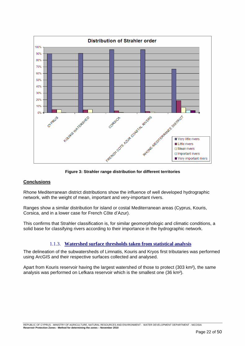
Figure 3: Strahler range distribution for different territories ............................................................ 22
REPUBLIC OF CYPRUS - MINISTRY OF AGRICULTURE, NATURAL RESOURCES AND ENVIRONMENT - WATER DEVELOPMENT DEPARTMENT - NICOSIA Reservoir Protection Zones - Method for determining the zones – November 2010
Page 5 of 50
1. Introduction
1.1. Context of the mission
The Water Development Department (WDD) of the Ministry of Agriculture, Natural Resources and Environment, wishes to implement Reservoir Protection Zones for the reservoirs that are used for drinking water purposes by applying the technical criteria and methods described in the document: TECHNICAL CRITERIA AND METHODS FOR ESTABLISHING RESERVOIR PROTECTION ZONES. This report was established in 2006 with European Union funds using the Technical Assistant Information Exchange Instrument (TAIEX). In the following, it will be called “2006 report”. The 2006 report established three reservoir protection zones: Immediate, Close and Distant protection Zones and proposed a semi-automatic method for the delineation of the Close protection zone by means of GIS tools. In conclusion, the 2006 report proposed a step by step implementation and test phase of the delineation method on a reservoir. KOURIS reservoir was selected for that purpose. The implementation of the test phase is the object of the mission which is organised in two phases. The first phase took place between May 5 to May 14, 2009. This report is the conclusion of this first mission and a preparation of the second phase mission; at the issue of this second mission, definitive documents will be established:
- method for determining reservoir protection zones and attached ordinance; - ordinance for KOURIS reservoir, as an enforcement of this method.
1.2. General program of the mission
Tuesday, 5 : Introduction meeting - Office work Wednesday, 6 : Field visit in Kouris watershed
Thursday, 7 : Field visit in Kouris watershed Friday, 8 : Work with GIS Engineer (morning), Office work (afternoon)
Monday, 11 : Work with GIS Engineer (morning), Office work (afternoon) Tuesday, 12 : Work with GIS Engineer (morning), Office work (afternoon)
Wednesday, 13 : Final meeting
1.3. Acknowledgements
The expert wishes to thank the Water Development Department and especially:
- Mr Sofoclis ALETRARIS – Director of the Water Development Department for his welcoming and fixing the ambition of the mission.
and
1. Mr Stefanos PAPATRIFONOS - Head of the Division of Water Resources for the attention taken to the organisation of the mission and decisions for strategic choices in the method.
2. Mrs Natasa NEOKLEOUS - Hydrologist - Division of Hydrometry Project manager for the reservoirs protection project, for the preparation and course of the mission, help, care and advices for the god achievement of the project.
3. Mr Kostas ARISTEIDOU - Hydrologist - Division of Hydrology & Hydrogeology for his high expertise level in GIS modelling closely connected with field understanding.
REPUBLIC OF CYPRUS - MINISTRY OF AGRICULTURE, NATURAL RESOURCES AND ENVIRONMENT - WATER DEVELOPMENT DEPARTMENT - NICOSIA Reservoir Protection Zones - Method for determining the zones – November 2010
Page 6 of 50
2. Summary of general principles
2.1. General considerations for reservoir protection
In the purpose of protecting a reservoir from pollution of its water, it is obvious that the ideal protection zone for a reservoir is its whole watershed1. But, as prevention of pollution means constraints on a majority of human activities, the setting of a too large protection zone is source of conflicts and will drive at least to the weakening of the protection system through a progressive non respect of the regulation attached. The difficulty increases in densely populated areas. In all countries, the main weakness of protection zones is their effective implementation and respect. So, better is to aim for limited but effective and respected protection zone perimeters instead of large non respected perimeters. The proposition for Cyprus protection reservoirs by the mean of different zones carrying specific protection constraints is closely adapted from the French regulation; the same considerations are also found in other countries regulations which set buffer zones around the reservoir and buffer strips along its tributaries.
2.2. Four reservoir protection zones
The reservoir protection zones are composed of four protection areas: � an Immediate Protection Zone � a Close Protection Zone � a Distant Protection Zone � a Riparian Protection Strip along all perennial or temporary rivers
2.2.1. The Immediate Protection Zone (IPZ)
This zone concerns the immediate environment of the pumping installations and equipment which are generally near to the dam of the reservoir. The goal of this perimeter is to:
� forbid access to the pumping point and to the treatment or pumping station ; � prevent damages on structures ; � prevent direct voluntary or involuntary introduction of pollutants in the water ; � protect the pumping zone from direct runoff and risk of pollutant spill from the banks.
Delineation: The delineation of the IPZ is applied according to the layout of each reservoir. Its surface is limited (some hundred square meters to some hectares) and its perimeter includes a part of the banks, a part of the lake and if necessary, a part of the river. In the Immediate Protection Zone, all activities are prohibited except the ones which are necessary to operate the installation and to maintain the equipment.
2.2.2. The Close Protection Zone (CPZ)
The goal of the CPZ is to keep the reservoir and the rivers that feed into it away from point and non-point source pollution, accidental or non-accidental pollution which can be driven to them directly or by surface or subsurface runoff. 1 Any area lying within the drainage basin of any reservoir.
REPUBLIC OF CYPRUS - MINISTRY OF AGRICULTURE, NATURAL RESOURCES AND ENVIRONMENT - WATER DEVELOPMENT DEPARTMENT - NICOSIA Reservoir Protection Zones - Method for determining the zones – November 2010
Page 7 of 50
Delineation: The delineation of the CPZ includes the immediate catchment area of the reservoir and the rivers whose flow contribution is considered as significant.
Any activity, deposit or installation which is likely to be directly or indirectly the cause of pollution or pollution vectors must be regulated or forbidden (a non-limiting list is given).
The extend of the CPZ is a compromise between the necessity of protection and the constraints to economic activities.
2.2.3. The Distant Protection Zone (DPZ)
This zone reinforces the Close Protection Zone. Delineation: Considering the very short time of concentration2 of the Cyprus reservoir watersheds, the Distant Protection Zone is defined as the whole watershed minus the Immediate and Close protection Zones. In the DPZ, the administration pays special attention to the major sources and risks of pollution and takes preventive actions.
2.2.4. The Riparian Protection Strip
The goal of the Riparian Protection Strip is to preserve: 4. fauna and flora species ; 5. the rivers away from direct pollution due to activities close to the river.
Delineation: along all the temporary or perennial river reaches in the reservoir’s catchment area as these are defined in the Cadastral maps a Riparian Protection Strip of 10 meters is delineated on each side of the stream axis. The RPS should be kept free of any construction or potential polluting activity or equipment and the vegetation should be maintained at its maximum possible natural status. 2 The time needed for a drop of water to reach the outlet of a catchment from the most remote location in the catchment.

REPUBLIC OF CYPRUS - MINISTRY OF AGRICULTURE, NATURAL RESOURCES AND ENVIRONMENT - WATER DEVELOPMENT DEPARTMENT - NICOSIA Reservoir Protection Zones - Method for determining the zones – November 2010
Page 8 of 50
3. Method for establishing the Immediate Protection Zone (IPZ)
3.1. Goal of the IPZ
This zone concerns the immediate environment of the pumping installations, water intake structure and equipment which are generally near the dam of the reservoir. The goal of this perimeter is to:
� forbid access to the water intake structure and to the pumping station; � prevent damages on structures; � prevent direct voluntary or involuntary introduction of pollutants in the water; � protect the pumping area from direct runoff and risk of pollutant spill from the banks.
3.2. Delineation of the IPZ
The IPZ is specific to each reservoir because it depends on the lie of the land. Its delineation is to be made by an expert, applying and adapting to local configuration the following rules:
� Its surface is generally limited (some hundred square meters to some hectares) and its perimeter includes : o a part of the banks ; o a part of the lake ; o and if necessary, a part of the river.
� Depending on the site configuration, the IPZ perimeter can be constituted of separate zones.
� The main purpose is to avoid access to the water intake structure and to the pumping station, by the mean of specific equipment: fences, gates, buoys line.
For what concerns access by unauthorized persons, three cases of situation are to be taken into consideration:
1. Normal persons which are not ill intentioned (walkers, fishermen …). Their polluting potential is weak (except exceptionally a risk of petrol pollution if having a motor-boat engine problem in the vicinity of the intake). Simple protections (fences, signs, buoys lines) will be enough to avoid them to approach sensible areas and/or to be too much curious.
2. Ill-intentioned persons, opportunist thieves can be a danger for the safety of equipments. Their targets will be building containing equipments, tools, spare parts … Strong doors and gates, windows bars, fences with a top line of barbed wire are necessary.
3. Saboteurs and terrorists are the real great danger for the pumping and intake installations.
If a situation occurs with the risk of sabotage and terrorism, above mentioned protection, as for any other strategic water supply equipment, will need to be strengthened by the mean of military protection. The equipment which is the most sensible is the intake, because of the risk of pouring of toxics in its vicinity. An area of a minimum diameter of 150 m around the intake will be kept out of access (100 m. is the maximum distance for throwing objects).
REPUBLIC OF CYPRUS - MINISTRY OF AGRICULTURE, NATURAL RESOURCES AND ENVIRONMENT - WATER DEVELOPMENT DEPARTMENT - NICOSIA Reservoir Protection Zones - Method for determining the zones – November 2010
Page 9 of 50
3.3. Physical protection This chapter describes physical protection to be put up in the cases 1 and 2 described above:
3.3.1. Protection of installation, building and equipments
a) Fences and gates: Closing any sensible area; b) Anti-breaking and entering alarm system, if necessary; c) Guarding of the installation, if necessary;
3.3.2. Protection of the immediate surroundings of the dam and intake
d) Ditches: If there is a possibility that an accidental spill (due to a truck accident for example) on a nearby road or parking place reaches the pumping zone, ditches shall be excavated in order to stop and contain the spill. Depending on local conditions, the spill could be canalized to a safety basin or at least downstream the dam.
e) Buoys line: a buoys line on the lake and/or on the river. This equipment is employed to forbid the approaching of boats or swimmers;
f) A fence erected on the bank can make the connection with the buoys line, even if a zone cannot be fenced because of water level variations;
g) Buoys line and fences will determine an area equal or greater than a 100 meters circle around the intake.
h) “No-entry” signs must be regularly placed on the fences or on the parts which cannot be fenced (banks);
i) Floating dam: In case of an accident by floating pollutants like hydrocarbons (petrol, diesel or fuel oil, …), and if an alert is possible before the pollution reaches the intake structure, the temporary installation of a floating dam can be effective in preventing pollutants reaching the intake if installed around the pumping installation. It must be available within a short time notice, stored on site or out of site by a permanently mobilizable service, in a reasonable distance. According to the layout of the place, one or several installation sketches must be prepared. Regular alert and installation exercises must be performed.
3.4. Chemicals and hydrocarbon products The storage of all chemical products and hydrocarbons necessary to operate or maintain the equipment will be kept within the minimum necessary amounts. All tanks must be located inside an impervious structure (generally concrete slab and walls) able to retain the whole content of the tank in case of leakage of the tank.
3.5. Roads inside or in the vicinity of the IPZ When possible, the access road to the reservoir should be through a non-asphalted dead-end road in order to limit traffic around the reservoir. If a road reaches the dam or the reservoir and allows “through traffic”, the traffic should be deviated and the access road to the dam converted to a dead end road. Any unavoidable “through traffic” road lying near the dam or the river banks must be equipped with crash barriers.
If there is a possibility that on a “through traffic” road, an accidental spill (due to a truck accident for example) reaches the pumping zone, ditches shall be excavated in order to contain the spill and divert it away from the reservoir. According to local conditions, the spill could be channeled to a safety basin or at least downstream the dam.
REPUBLIC OF CYPRUS - MINISTRY OF AGRICULTURE, NATURAL RESOURCES AND ENVIRONMENT - WATER DEVELOPMENT DEPARTMENT - NICOSIA Reservoir Protection Zones - Method for determining the zones – November 2010
Page 10 of 50
3.6. Vegetation The vegetation growing within this perimeter will be mechanically managed and neither weed killer nor pesticide will be used.
3.7. Prescriptions in the IPZ
In the Immediate Protection Zone, all activities ar e prohibited except the ones which are necessary to operate the installation and to mainta in the equipment.
The land constituting this perimeter must compulsor y be the full property of the public authority in charge of the reservoir. For details, refer to the chapter general prescriptions of the ordinance document.

REPUBLIC OF CYPRUS - MINISTRY OF AGRICULTURE, NATURAL RESOURCES AND ENVIRONMENT - WATER DEVELOPMENT DEPARTMENT - NICOSIA Reservoir Protection Zones - Method for determining the zones – November 2010
Page 11 of 50
4. Method for establishing the Close Protection Zone (CPZ)
The goal of this perimeter is to keep the reservoir and the rivers away from: - accidental or non-accidental pollution which can be transported in the reservoir by direct
surface or subsurface runoff or by river stream flow; - non-point or point source pollution.
4.1. Prescriptions in the CPZ
In the Close Protection Zone, any activity, deposit or installation which is likely to be directly or indirectly the cause of pollution or pollution vectors of surface or underground waters, must be regulated or forbidden. For details, refer to the chapter general prescriptions of the ordinance document.
4.2. Delineation method of the Close Protection Zones (CPZ)
There are two main steps in setting the Close protection zone: 1) Identification of streams that should be included in the CPZ because their flow contribution
can be important enough to consider that if they sustain a pollution the consequences will be damageable for the quality of water in the reservoir;
2) Determination of the sensible areas that should form the protection zone of the streams identified in step 1: areas where pollution can be directly transferred in the stream by surface runoff on slopes or underground flow.
In concrete terms, these considerations drive to identify:
1) Streams whose flow contribution is significant; 2) Valley areas where pollution can be brought quickly in the river because:
a. slopes are steep enough to bring pollutions into the stream; and/or
b. areas are close enough to the banks of the stream or to the reservoir to allow for a high probability of transport of pollution into the water.
4.2.1. Rules for the determination of Streams whose flow contribution is significant
Tributaries order or sub-watershed size? The 2006 report stated that first tributaries of main rivers where to be included in the CPZ. But a more thorough analysis of the hydrographic network showed that this approach is not always correct as some secondary tributaries might have the same or higher hydrologic importance than some first ones. So, it was decided to abandon this classification (first, second … tributaries) and use a classification which could be more representative of the flow contribution of the different streams of the watershed: the sub-watershed size. The purpose is to include in the CPZ important parts of the hydrographic network:
- take watersheds of certain importance ; - not forget small ones which can or could suffer pressures.
Main rivers: are identified as the ones which directly feed the reservoir and/or their flow contribution is significant.
REPUBLIC OF CYPRUS - MINISTRY OF AGRICULTURE, NATURAL RESOURCES AND ENVIRONMENT - WATER DEVELOPMENT DEPARTMENT - NICOSIA Reservoir Protection Zones - Method for determining the zones – November 2010
Page 12 of 50
For example, in Kouris case, there are 4 main rivers, one of them being little. From east to west: Limnatis, Kouris, Alassa river and Kryos. Three types of analysis have been performed on Kouris reservoir sub-watersheds and tributaries, Kouris reservoir having the largest watershed of those to protect (303 km²), the same analysis was made on Lefkara reservoir which is the smallest one (36 km²). The three types of analysis were respectively based on:
- predetermined sub-watersheds values ; - order of tributaries in the hydrographic network ; - statistical analysis of the size of sub-watershed (first tributaries only).
���� For more details see: ANNEX – CPZ: Rules for the determination of streams whose flow contribution is significant. These three types of analysis tended towards similar conclusions and allow for a final rule proposal: The part of main rivers or tributaries that are to be included in the CPZ are those :
o whose sub-watershed size is more than 3 km² ; OR
o whose sub-watershed surface is more than 5% of the whole watershed.
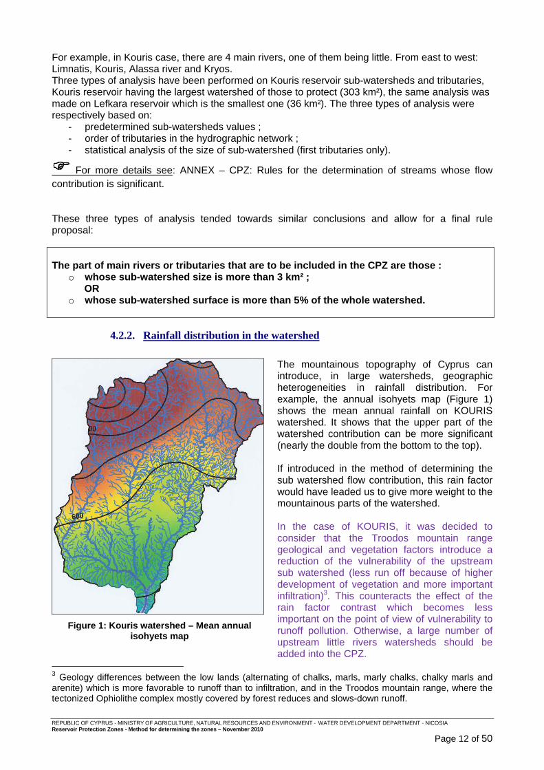
4.2.2. Rainfall distribution in the watershed
Figure 1: Kouris watershed – Mean annual
isohyets map
The mountainous topography of Cyprus can introduce, in large watersheds, geographic heterogeneities in rainfall distribution. For example, the annual isohyets map (Figure 1) shows the mean annual rainfall on KOURIS watershed. It shows that the upper part of the watershed contribution can be more significant (nearly the double from the bottom to the top). If introduced in the method of determining the sub watershed flow contribution, this rain factor would have leaded us to give more weight to the mountainous parts of the watershed. In the case of KOURIS, it was decided to consider that the Troodos mountain range geological and vegetation factors introduce a reduction of the vulnerability of the upstream sub watershed (less run off because of higher development of vegetation and more important infiltration)3. This counteracts the effect of the rain factor contrast which becomes less important on the point of view of vulnerability to runoff pollution. Otherwise, a large number of upstream little rivers watersheds should be added into the CPZ.
3 Geology differences between the low lands (alternating of chalks, marls, marly chalks, chalky marls and arenite) which is more favorable to runoff than to infiltration, and in the Troodos mountain range, where the tectonized Ophiolithe complex mostly covered by forest reduces and slows-down runoff.
REPUBLIC OF CYPRUS - MINISTRY OF AGRICULTURE, NATURAL RESOURCES AND ENVIRONMENT - WATER DEVELOPMENT DEPARTMENT - NICOSIA Reservoir Protection Zones - Method for determining the zones – November 2010
Page 13 of 50
This sketch can be applied to any large watershed, whose upstream part is lying over mountainous areas where mean annual rainfall is more important that downstream: the condition to fulfil is that vegetation is well developed in those mountainous areas.
4.2.3. Rules of determination of sensible perimeters for the protection of rivers : high slopes or/and high proximity
The goal of these perimeters is to keep the rivers that feed into the reservoir away from point or non-point source or accidental pollution by surface or subsurface runoff on river banks slopes. A protection buffer zone is to be applied along the main rivers and tributaries whose flow contribution is significant in order to:
- keep at a certain distance forbidden activities; - do not allow forbidden activities on sloping sides of the rivers valleys.
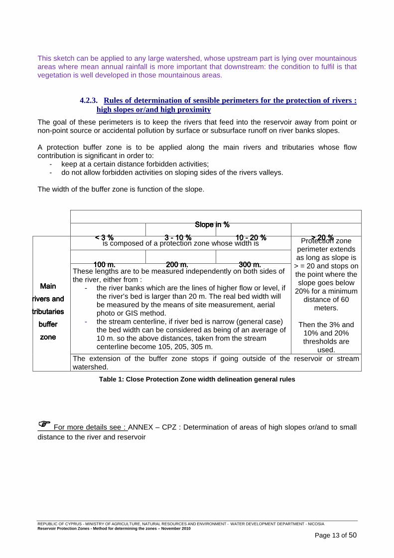
The width of the buffer zone is function of the slope.
Slope in %Slope in %Slope in %Slope in %
< 3< 3< 3< 3 %%%% 3333 ---- 10101010 %%%% 10101010 ---- 20202020 %%%% > 20> 20> 20> 20 %%%%
Main Main Main Main rivers and rivers and rivers and rivers and tributaries tributaries tributaries tributaries buffer buffer buffer buffer zone zone zone zone
is composed of a protection zone whose width is Protection zone perimeter extends as long as slope is
> = 20 and stops on the point where the slope goes below
20% for a minimum distance of 60
meters.
Then the 3% and 10% and 20% thresholds are
used.
100 m.100 m.100 m.100 m. 200 m.200 m.200 m.200 m. 303030300 m.0 m.0 m.0 m. These lengths are to be measured independently on both sides of the river, either from :
- the river banks which are the lines of higher flow or level, if the river’s bed is larger than 20 m. The real bed width will be measured by the means of site measurement, aerial photo or GIS method.
- the stream centerline, if river bed is narrow (general case) the bed width can be considered as being of an average of 10 m. so the above distances, taken from the stream centerline become 105, 205, 305 m.
The extension of the buffer zone stops if going outside of the reservoir or stream watershed.
Table 1: Close Protection Zone width delineation general rules
���� For more details see : ANNEX – CPZ : Determination of areas of high slopes or/and to small distance to the river and reservoir

REPUBLIC OF CYPRUS - MINISTRY OF AGRICULTURE, NATURAL RESOURCES AND ENVIRONMENT - WATER DEVELOPMENT DEPARTMENT - NICOSIA Reservoir Protection Zones - Method for determining the zones – November 2010
Page 14 of 50
4.2.4. Rules for the determination of other streams around the reservoir whose flow contribution is sensible
The purpose is to include in the CPZ Sensible streams of any size, whose flow can directly enter the reservoir’s lake, or reach the main rivers in the immediate vicinity of the reservoir’s lake, and bring pollution. Sensible streams are the streams which :
- directly flow in the reservoir’s lake at its higher possible level excluding the rivers identified as main rivers;
- directly flow in the main rivers, between the confl uence of this river with the reservoir’s lake at its higher possible level, and a point located 1 km upstream along the river;
- the protection of these sensible streams is accompl ished by including their
watershed in the CPZ.
Note: This 1 km value is a compromise between:
- a value that might be quite higher, moving this point very close of the top of the main rivers watershed but inhibiting development on a very large part of the watershed ;
- the choice of enforcing adequate protection rules. So, the administration is highly encouraged to incr ease this value every time the reality on the ground will require it.
REPUBLIC OF CYPRUS - MINISTRY OF AGRICULTURE, NATURAL RESOURCES AND ENVIRONMENT - WATER DEVELOPMENT DEPARTMENT - NICOSIA Reservoir Protection Zones - Method for determining the zones – November 2010
Page 15 of 50
4.3. Step by step Close Protection Zone delineation rules
As a summary of above methods and rules, the construction of the Close Protection Zone delineation follows the steps below:
4.3.1. Streams whose flow contribution is significant
4.3.1.1. Identification These streams are part of main rivers or tributaries whose:
o sub-watershed size is more than 3 km² ; OR
o sub-watershed surface is more than 5% of the whole watershed.
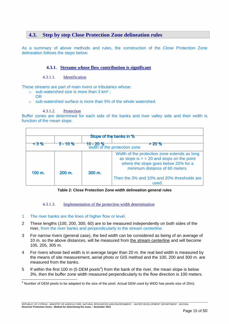
4.3.1.2. Protection Buffer zones are determined for each side of the banks and river valley side and their width is function of the mean slope.
Slope Slope Slope Slope of the banks of the banks of the banks of the banks in %in %in %in %
< 3< 3< 3< 3 %%%% 3333 ---- 10101010 %%%% 10101010 ---- 20202020 %%%% > 20> 20> 20> 20 %%%% width of the protection zone
100 m.100 m.100 m.100 m. 200 m.200 m.200 m.200 m. 300 m.300 m.300 m.300 m.
Width of the protection zone extends as long as slope is > = 20 and stops on the point where the slope goes below 20% for a
minimum distance of 60 meters.
Then the 3% and 10% and 20% thresholds are used.
Table 2: Close Protection Zone width delineation general rules
4.3.1.3. Implementation of the protection width determination
1 The river banks are the lines of higher flow or level.
2 These lengths (100, 200, 300, 60) are to be measured independently on both sides of the river, from the river banks and perpendicularly to the stream centerline.
3 For narrow rivers (general case), the bed width can be considered as being of an average of 10 m. so the above distances, will be measured from the stream centerline and will become 105, 205, 305 m.
4 For rivers whose bed width is in average larger than 20 m. the real bed width is measured by the means of site measurement, aerial photo or GIS method and the 100, 200 and 300 m. are measured from the banks.
5 If within the first 100 m (5 DEM pixels4) from the bank of the river, the mean slope is below 3%, then the buffer zone width measured perpendicularly to the flow direction is 100 meters.
4 Number of DEM pixels to be adapted to the size of the pixel. Actual DEM used by WDD has pixels size of 20m).
REPUBLIC OF CYPRUS - MINISTRY OF AGRICULTURE, NATURAL RESOURCES AND ENVIRONMENT - WATER DEVELOPMENT DEPARTMENT - NICOSIA Reservoir Protection Zones - Method for determining the zones – November 2010
Page 16 of 50
6 If the previous condition is not respected, and if during the first 200 m (10 DEM pixels) from the river, the mean slope is below 10%, then the buffer zone width measured perpendicularly to the flow direction is 200 meters.
7 If the previous condition is not respected, and if during the first 300 m (15 DEM pixels) from the river, the mean slope is below 20%, then the buffer zone width measured perpendicularly to the flow direction is 300 meters.
8 If within these 300 meters zone, the slope of the natural terrain remains greater than 20%, the perimeter will be continued as far as the point where the slope goes below 20% for a minimum distance of 60 meters.
9 In any case, care will be taken to stop the extension of the buffer zone if going outside of the reservoir or tributary watershed.
4.3.2. Other streams around the reservoir whose flow contribution is sensible
4.3.2.1. Identification These streams are the ones which:
• directly flow in the reservoir’s lake at its higher possible level excluding the rivers identified as main rivers;
• directly flow in the main rivers, between the confluence of this river with the reservoir’s lake at its higher possible level, and a point located 1 km minimum upstream along the river.
4.3.2.2. Protection The protection of these sensible streams is accomplished by including their watershed in the CPZ.
4.3.3. Reservoir’s lake
The whole reservoir, considered at its highest possible water level, is a part of the Close Protection Zone.
REPUBLIC OF CYPRUS - MINISTRY OF AGRICULTURE, NATURAL RESOURCES AND ENVIRONMENT - WATER DEVELOPMENT DEPARTMENT - NICOSIA Reservoir Protection Zones - Method for determining the zones – November 2010
Page 17 of 50
5. The Distant Protection Zone (DPZ) The Distant protection Zone reinforces the Close Protection Zone. The hydromorphological feature of the natural water network in Cyprus watersheds makes the rivers of the CPZ very sensitive to the water quality of flow which can come quickly from the streams outside the CPZ. Consequently, great care must be taken in water quality management in the DPZ.
5.1. Delineation of the DPZ
The fact that the whole watershed can contribute to the flow received by the reservoir under high flow conditions implies that the limits of the Distant Protection Zone are the whole watershed of the reservoir minus the Immediate and Close protection Zones5.
5.2. Requirements in the DPZ
The authority in charge of the protection of the resource shall identify existing and potential new activities within the watershed that generally can cause degradation and impair water quality of the reservoir’s water. For details, refer to the chapter general prescriptions of the ordinance document. 5 Considering the very short time of concentration of reservoir watersheds, it is the whole watershed that will be considered as the Distant Protection Zone.
REPUBLIC OF CYPRUS - MINISTRY OF AGRICULTURE, NATURAL RESOURCES AND ENVIRONMENT - WATER DEVELOPMENT DEPARTMENT - NICOSIA Reservoir Protection Zones - Method for determining the zones – November 2010
Page 18 of 50
6. The Riparian protection Strip (RPS) The goal of the rivers Riparian Protection Strip is to preserve:
6. fauna and flora species ; 7. the rivers away from direct pollution due to activities close to the river.
6.1. Delineation of the RPS
The RPS is established for all the temporary or perennial river reaches in the reservoir’s cathment area as these are defined in the Cadastral maps of the Lands and Surveys Department. The RPS consists of a strip of 10 meters on each side of the stream axis. Its extension is defined on site, measuring a distance of 10 meters, perpendicularly to the direction of flow, on both left and right banks of the stream.
6.2. Requirements in the RPS
In the RPS, any activity, deposit or installation that is likely to be directly or indirectly the cause of pollution of the river’s water is forbidden. The RPS will be kept without any construction, earth work, agricultural activity, roads … The use and storage of any chemical or hydrocarbon product is forbidden in this riparian protection strip. The vegetation will be kept at its maximum possible growth and priority should be given to the preservation of native vegetation trees, shrubs and grass.
REPUBLIC OF CYPRUS - MINISTRY OF AGRICULTURE, NATURAL RESOURCES AND ENVIRONMENT - WATER DEVELOPMENT DEPARTMENT - NICOSIA Reservoir Protection Zones - Method for determining the zones – November 2010
Page 19 of 50
AANNNNEEXXEESS

REPUBLIC OF CYPRUS - MINISTRY OF AGRICULTURE, NATURAL RESOURCES AND ENVIRONMENT - WATER DEVELOPMENT DEPARTMENT - NICOSIA Reservoir Protection Zones - Method for determining the zones – November 2010
Page 20 of 50
1. ANNEX – CPZ: Rules for the determination of streams whose flow contribution is significant
The purpose is to include in the CPZ important parts of the hydrographic network. Main rivers are identified as the ones which directly feed the reservoir and have significant flow contribution. In Kouris case, there are 4 main rivers, one of them being little. From east to west:
- Limnatis ; - Kouris - “Alassa river” (the little one) ; - Kryos.
The 2006 report stated that first tributaries where to be included in the CPZ. But a more thorough analysis of the hydrographic network showed that this approach is not always correct as some secondary tributaries might have the same of higher importance than first ones. So, it was decided to abandon this classification (first, second … tributaries) and use one which could be more representative of the flow contribution of the different areas of the watershed. Three methods where tested for identifying which sub-watersheds are to be included in the CPZ.
1.1. The three tested methods
1.1.1. Predetermined value
The first approach was to include in the CPZ, all parts of rivers whose upstream watershed is larger than X km². With X equal to 2, 4 or 5 km². This method is simple but arbitrary. This means that if such a surface limit is going be used, the value must be settled on technical arguments.
1.1.2. Importance of the tributaries using hydrographic network steam order (Strahler classification)
Classification of hydrographic network is accomplished through the numbering of river segments (main river and tributaries) and reflects the dendritic shape of river networks. Several classification systems exist, but the most widely accepted and most commonly used, which has been used for the Water Framework Directive identification of reference monitoring network, is the Strahler classification (STRAHLER A.N., 1957 - Quantitative analysis of watershed geomorphology. Trans. Amer. Geophys. Union, 38, p. 913-920).

REPUBLIC OF CYPRUS - MINISTRY OF AGRICULTURE, NATURAL RESOURCES AND ENVIRONMENT - WATER DEVELOPMENT DEPARTMENT - NICOSIA Reservoir Protection Zones - Method for determining the zones – November 2010
Page 21 of 50
This classification allows for the description without ambiguity the development of the drainage system of a basin from upstream to downstream. It is based on the following rules :
- any river segment without any tributary is assigned the order number of 1;
- any river segment downstream of the
confluence of two river segments of different order takes the higher order of the two;
- a river segment downstream of the
confluence of two river segments of the same order, is assigned an order number increased by one.
Figure 2: Strahler classification
This Strahler classification was available in the WDD GIS geodatabase for the rivers shown on the topographic maps 1:50000. The results of the Strahler classification were compared for different areas:
- All Cyprus rivers ; - Kouris rivers ; - Corsica (for the similarities of geologic, morphology and climatic conditions) ; - French Mediterranean east coast (for the similarities of geologic, morphology and climatic
conditions) ; - Whole French Rhône-Mediterranée District (mixing continental and Mediterranean
conditions).
Very little rivers Little rivers Mean rivers Important
rivers
Very important
rivers Total length
Stralher 0 to 3 Stralher 4 Stralher 5 to
6 Strahler 7 Strahler 8 Km
CYPRUS 17 947 994 917 32 0
19 889 90.2% 5.0% 4.6% 0.2% 0.0%
KOURIS 1 098 53 62 0 0
1 214 90.5% 4.4% 5.1% 0.0% 0.0%
CORSICA 12 263 388 99 0 0
12 750 96.2% 3.0% 0.8% 0.0% 0.0%
FRENCH COTE AZUR COASTAL
RIVERS
15 205 365 218 0 0 15 789
96.3% 2.3% 1.4% 0.0% 0.0%
FRENCH COTE AZUR COASTAL BV
4 794 81 44 0 0 4 918
97.5% 1.6% 0.9% 0.0% 0.0% RHONE-
MEDITERRANEE DISTRICT
28 625 7 968 3 376 1 630 1 430 43 029
66.5% 18.5% 7.8% 3.8% 3.3%
Table 3: Strahler range distribution for different territories
REPUBLIC OF CYPRUS - MINISTRY OF AGRICULTURE, NATURAL RESOURCES AND ENVIRONMENT - WATER DEVELOPMENT DEPARTMENT - NICOSIA Reservoir Protection Zones - Method for determining the zones – November 2010
Page 22 of 50
Figure 3: Strahler range distribution for different territories Conclusions Rhone Mediterranean district distributions show the influence of well developed hydrographic network, with the weight of mean, important and very-important rivers. Ranges show a similar distribution for island or costal Mediterranean areas (Cyprus, Kouris, Corsica, and in a lower case for French Côte d’Azur). This confirms that Strahler classification is, for similar geomorphologic and climatic conditions, a solid base for classifying rivers according to their importance in the hydrographic network.
1.1.3. Watershed surface thresholds taken from statistical analysis
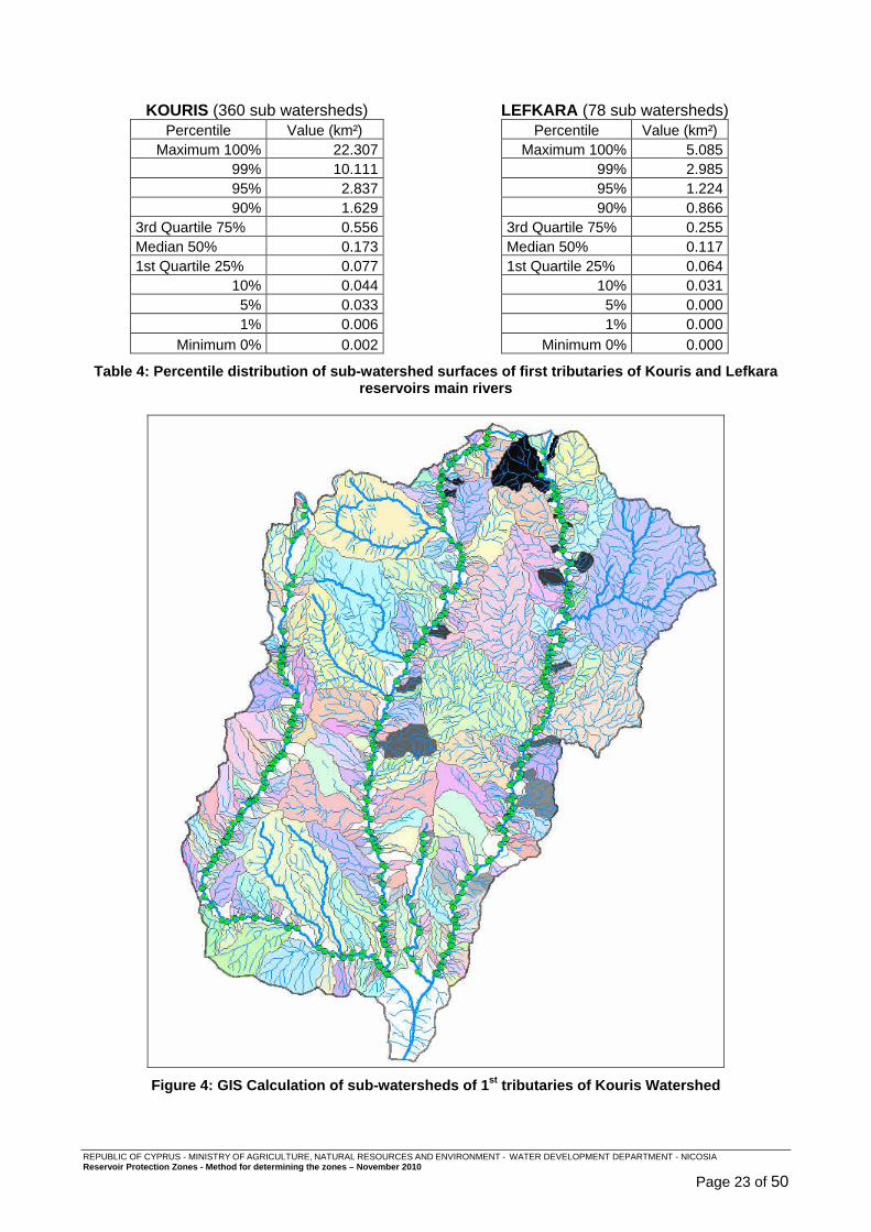
The delineation of the subwatersheds of Limnatis, Kouris and Kryos first tributaries was performed using ArcGIS and their respective surfaces collected and analysed. Apart from Kouris reservoir having the largest watershed of those to protect (303 km²), the same analysis was performed on Lefkara reservoir which is the smallest one (36 km²).
REPUBLIC OF CYPRUS - MINISTRY OF AGRICULTURE, NATURAL RESOURCES AND ENVIRONMENT - WATER DEVELOPMENT DEPARTMENT - NICOSIA Reservoir Protection Zones - Method for determining the zones – November 2010
Page 23 of 50
KOURIS (360 sub watersheds) LEFKARA (78 sub watersheds)
Percentile Value (km²) Maximum 100% 22.307
99% 10.111 95% 2.837 90% 1.629
3rd Quartile 75% 0.556 Median 50% 0.173 1st Quartile 25% 0.077
10% 0.044 5% 0.033 1% 0.006
Minimum 0% 0.002
Percentile Value (km²) Maximum 100% 5.085
99% 2.985 95% 1.224 90% 0.866
3rd Quartile 75% 0.255 Median 50% 0.117 1st Quartile 25% 0.064
10% 0.031 5% 0.000 1% 0.000
Minimum 0% 0.000
Table 4: Percentile distribution of sub-watershed surfaces of f irst tributaries of Kouris and Lefkara reservoirs main rivers
Figure 4: GIS Calculation of sub-watersheds of 1 st tributaries of Kouris Watershed
REPUBLIC OF CYPRUS - MINISTRY OF AGRICULTURE, NATURAL RESOURCES AND ENVIRONMENT - WATER DEVELOPMENT DEPARTMENT - NICOSIA Reservoir Protection Zones - Method for determining the zones – November 2010
Page 24 of 50
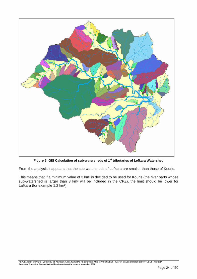
Figure 5: GIS Calculation of sub-watersheds of 1 st tributaries of Lefkara Watershed
From the analysis it appears that the sub-watersheds of Lefkara are smaller than those of Kouris. This means that if a minimum value of 3 km² is decided to be used for Kouris (the river parts whose sub-watershed is larger than 3 km² will be included in the CPZ), the limit should be lower for Lafkara (for example 1.2 km²).
REPUBLIC OF CYPRUS - MINISTRY OF AGRICULTURE, NATURAL RESOURCES AND ENVIRONMENT - WATER DEVELOPMENT DEPARTMENT - NICOSIA Reservoir Protection Zones - Method for determining the zones – November 2010
Page 25 of 50
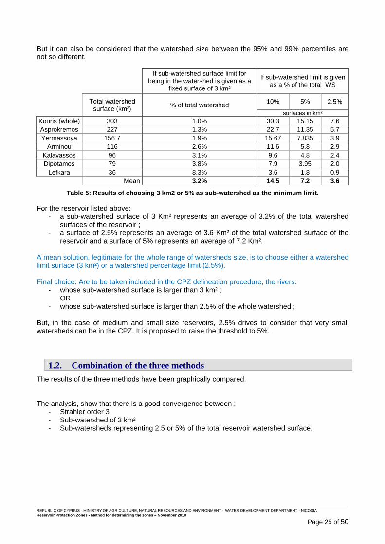
But it can also be considered that the watershed size between the 95% and 99% percentiles are not so different.
If sub-watershed surface limit for
being in the watershed is given as a fixed surface of 3 km²
If sub-watershed limit is given as a % of the total WS
Total watershed surface (km²) % of total watershed 10% 5% 2.5%
surfaces in km² Kouris (whole) 303 1.0% 30.3 15.15 7.6 Asprokremos 227 1.3% 22.7 11.35 5.7 Yermassoya 156.7 1.9% 15.67 7.835 3.9
Arminou 116 2.6% 11.6 5.8 2.9 Kalavassos 96 3.1% 9.6 4.8 2.4 Dipotamos 79 3.8% 7.9 3.95 2.0
Lefkara 36 8.3% 3.6 1.8 0.9 Mean 3.2% 14.5 7.2 3.6
Table 5: Results of choosing 3 km2 or 5% as sub-watershed as t he minimum limit. For the reservoir listed above:
- a sub-watershed surface of 3 Km² represents an average of 3.2% of the total watershed surfaces of the reservoir ;
- a surface of 2.5% represents an average of 3.6 Km² of the total watershed surface of the reservoir and a surface of 5% represents an average of 7.2 Km².
A mean solution, legitimate for the whole range of watersheds size, is to choose either a watershed limit surface (3 km²) or a watershed percentage limit (2.5%). Final choice: Are to be taken included in the CPZ delineation procedure, the rivers:
- whose sub-watershed surface is larger than 3 km² ; OR
- whose sub-watershed surface is larger than 2.5% of the whole watershed ; But, in the case of medium and small size reservoirs, 2.5% drives to consider that very small watersheds can be in the CPZ. It is proposed to raise the threshold to 5%.
1.2. Combination of the three methods
The results of the three methods have been graphically compared. The analysis, show that there is a good convergence between :
- Strahler order 3 - Sub-watershed of 3 km² - Sub-watersheds representing 2.5 or 5% of the total reservoir watershed surface.

REPUBLIC OF CYPRUS - MINISTRY OF AGRICULTURE, NATURAL RESOURCES AND ENVIRONMENT - WATER DEVELOPMENT DEPARTMENT - NICOSIA Reservoir Protection Zones - Method for determining the zones – November 2010
Page 26 of 50
Figure 6: Graphical comparison of Strahler order and DA size for Ko uris Watershed
1.3. Final identification of main river and tributaries
The above analysis drives to propose the following rule: The main rivers and tributaries to be included in the CPZ delineation procedure are the ones :
- whose sub-watershed surface is larger than 3 km² ; OR
- whose sub-watershed surface is larger than 5% of the whole watershed.
REPUBLIC OF CYPRUS - MINISTRY OF AGRICULTURE, NATURAL RESOURCES AND ENVIRONMENT - WATER DEVELOPMENT DEPARTMENT - NICOSIA Reservoir Protection Zones - Method for determining the zones – November 2010
Page 27 of 50
2. ANNEX – CPZ : Determination of areas of high slopes or/and to small distance to the river and reservoir
The most common tool used internationally to set protection of reservoirs and streams is that of buffer zones along and around these water bodies. Buffer zones are composed of two parts:
- a riparian protection zone whose width is defined through rules ; - a zone where overbank slope gradient is over a threshold beyond which the risk for
pollution on the slopes reaching the water bodies is significant. The CPZ delineation method must include these two factors (riparian protection zone and slope), taking advantage of the international experience gained from similar practices.
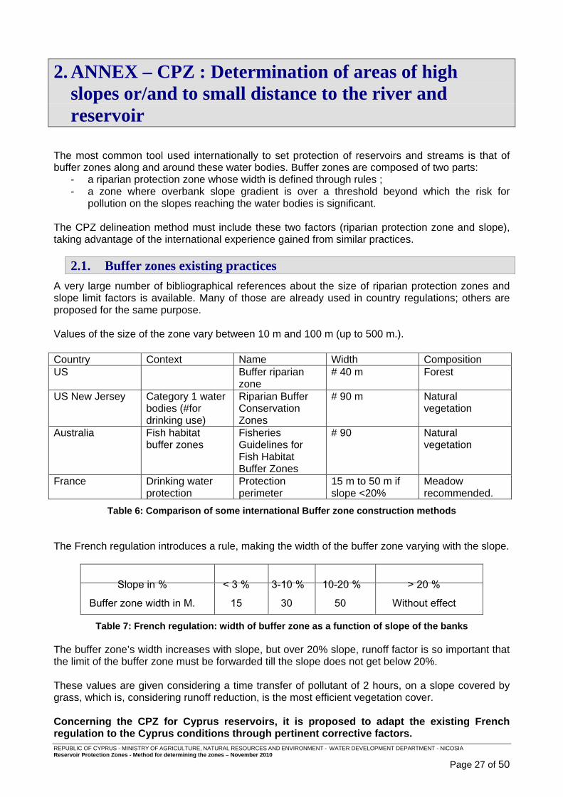
2.1. Buffer zones existing practices
A very large number of bibliographical references about the size of riparian protection zones and slope limit factors is available. Many of those are already used in country regulations; others are proposed for the same purpose. Values of the size of the zone vary between 10 m and 100 m (up to 500 m.). Country Context Name Width Composition US Buffer riparian
zone # 40 m Forest
US New Jersey Category 1 water bodies (#for drinking use)
Riparian Buffer Conservation Zones
# 90 m Natural vegetation
Australia Fish habitat buffer zones
Fisheries Guidelines for Fish Habitat Buffer Zones
# 90 Natural vegetation
France Drinking water protection
Protection perimeter
15 m to 50 m if slope <20%
Meadow recommended.
Table 6: Comparison of some international Buffer zone constructi on methods The French regulation introduces a rule, making the width of the buffer zone varying with the slope.
Slope in % < 3 % 3-10 % 10-20 % > 20 %
Buffer zone width in M. 15 30 50 Without effect
Table 7: French regulation: width of buffer zone as a function of slope of the banks The buffer zone’s width increases with slope, but over 20% slope, runoff factor is so important that the limit of the buffer zone must be forwarded till the slope does not get below 20%. These values are given considering a time transfer of pollutant of 2 hours, on a slope covered by grass, which is, considering runoff reduction, is the most efficient vegetation cover. Concerning the CPZ for Cyprus reservoirs, it is pro posed to adapt the existing French regulation to the Cyprus conditions through pertine nt corrective factors.
REPUBLIC OF CYPRUS - MINISTRY OF AGRICULTURE, NATURAL RESOURCES AND ENVIRONMENT - WATER DEVELOPMENT DEPARTMENT - NICOSIA Reservoir Protection Zones - Method for determining the zones – November 2010
Page 28 of 50
The French Regulation is proposed because: - it introduces a progressive factor for riparian pro tection zone which is less
penalizing for land owners ; - there is continuity between riparian protection zon e and zones where slope is
considered as too high to allow protection with a r iparian strip.
2.2. Research of pertinent corrective factors
Corrective factor for Cyprus conditions are to be found in order to set riparian protection zone width and slope threshold values.
2.2.1. Erosion parameters
Transportation of pollutants by runoff involves: - runoff sensu stricto for the soluble contaminants it can contain ; - soil erosion, or soil loss, for the non soluble contaminants contained in soil or linked with
clay-humus complexes that are transported during the erosion process. The main method of estimating soil losses from rainfall and runoff is the empirical equation called Universal Soil Loss Equation (USLE). It was developed in 1978 by statistical analyses of many plot-years of rainfall, runoff, and sediment loss data from many small plots located all over the world. A newer version of the USLE, called RUSLE (Revised Universal Soil Loss Equation) has been developed in 1991, by the introduction of agriculture considerations and is more detailed than the USLE : The Universal Soil Loss Equation is: A = RKLSCP Where A = average annual soil loss in tons per acre per year R = rainfall and runoff erosivity index for a given location K = soil erodibility factor L = slope length factor S = slope steepness factor C= cover and management factor P = conservation or support practice factor From the point of view of reservoir and river protection some terms of the equation are more significant while others can be considered as secondary:
• The erosion index (EI) for a given storm is a product of the kinetic energy of the falling raindrops and its maximum 30 minute intensity. The sum of these EI values over a year divided by 100 gives the annual R factor. Even if erosion is highly linked to rain, in our ca se there is no possibility of action on its value, and so R can be considered as an “extern al constant”;
• Soil erodibility (K) factor is a measure of the susceptibility of a given soil to erosion by
rainfall and runoff. The properties of a soil that influence its erodibility are: soil texture, soil structure, organic matter content, and soil permeability. To the scale of skin erosion which is involved in p ollutant transport by runoff, the differences between the various types of soils is c onsidered as non-significant, even if it exists. So it was decided not to introduce so il considerations in the method of delineation of the CPZ.

REPUBLIC OF CYPRUS - MINISTRY OF AGRICULTURE, NATURAL RESOURCES AND ENVIRONMENT - WATER DEVELOPMENT DEPARTMENT - NICOSIA Reservoir Protection Zones - Method for determining the zones – November 2010
Page 29 of 50
• The topographic factors Length (L) and Slope (S) are used to adjust the erosion rate based upon the length and steepness of the slope. The erosivity of runoff increases with the velocity of the runoff water. Steep slopes produce high runoff velocities. Soil loss increases with increasing slope length due to the greater volume of runoff accumulating on the longer slope lengths. The slope length is the distance from the point of origin of the runoff to the point where the slope steepness decreases sufficiently to cause deposition or to the point where runoff enters a well-defined channel. It is known that for the same slope steepness, eros ion will be more significant on longer slopes. But slope steepness remains the main parameter affecting erosion. On the other hand, as it cannot be known where the pollution could occur on the slope, the length of the slope loses some importanc e. Slope steepness is considered as a significant factor from the point of view of R ZP.
• The cover and management factor, C , is the ratio of soil loss from land use under specific
conditions to that from continuously fallow and tilled land. The USLE was developed for use on agricultural fields. It is adapted to use in non-agricultural conditions by appropriate selection of the C factor. This is often done by relating the land use conditions to some agricultural situation. For example, a shooting range with a grass cover might be assumed to be similar to a pasture. Annual values of C for various cover and management conditions are presented below.
Vegetal Canopy Cover That Contacts the Surface Type and Height Canopy Percent Ground Cover of Raised Canopy2 Covers3 % Type4 0 20 40 60 80 95-100 No appreciable canopy G .45 .20 .10 .042 .013 .003 W .45 .24 .15 .090 .043 .011 Canopy of tall weeds 25 G .36 .17 .09 .038 .012 .003 or short brush, W .36 .20 .13 .082 .041 .011 0.5 m (1.6 ft.) fall ht. 50 G .26 .13 .07 .035 .012 .003 W .26 .16 .11 .075 .039 .011 75 G .17 .10 .06 .031 .011 .003 W .17 .12 .09 .068 .038 .011 Appreciable brush 25 G .40 .18 .09 .040 .013 .003 or bushes, W .40 .22 .14 .085 .042 .011 2 m 6.6 ft. fall ht. 50 G .34 .16 .085 .038 .012 .003 W .34 .19 .13 .081 .041 .011 75 G .28 .14 .08 .036 .012 .003 W .28 .17 .12 .077 .040 .011 Trees but no appreciable, 25 G .42 .19 .10 .041 .013 .003 low brush , W .42 .23 .14 .087 .042 .011 4 m (13.1 ft.) fall ht. 50 G .39 .18 .09 .040 .013 .003 W .39 .21 .14 .085 .042 .011 75 G .36 .17 .09 .039 .012 .003 W .36 .20 .13 .083 .041 .011 1All values shown assume: (1) random distribution of mulch or vegetation, and (2) mulch of appreciable depth where it exists. Idle land refers to land with undisturbed profiles for at least a period of three consecutive years. 2Average fall height of waterdrops from canopy to soil surface. 3Portion of total-area surface that would be hidden from view by canopy in a vertical projection (a birds’s-eye view). 4G: Cover at surface is grass, grasslike plants, decaying compacted duff, or litter at least 2 inches deep. W: Cover at surface is mostly broadleaf herbaceous plants (as weeds with little lateral-root network near the surface, and/or undecayed residue).
Table 8: Cover management, “C” factors for permanent pasture, r angeland, and idle land
REPUBLIC OF CYPRUS - MINISTRY OF AGRICULTURE, NATURAL RESOURCES AND ENVIRONMENT - WATER DEVELOPMENT DEPARTMENT - NICOSIA Reservoir Protection Zones - Method for determining the zones – November 2010
Page 30 of 50
• The conservation practice factor (P), is used to account for the positive impacts of agricultural management practices as: planting on the contour, strip cropping, and use of terraces. For the need of CPZ method, P is considered as non- significant. Even if good practices bring a reducing factor of erosion and co nsequently of stream and water pollution, it must be reminded that agriculture is not encouraged in the CPZ.
Conclusion : Slope and soil Cover type are the two main factor s that should be taken into account concerning the risk of reservoir and strea m pollution from the riparian area.
2.2.2. Slope factor limits
Another important bibliographical reference is available on the subject of pollutant transport by run-off. Recent research on pesticide transport by run-off give pertinent informations. One of the formulas used in modelling the phenomenon is based on the model of LUTZ and MANIAK (1984, 1992) for the calculation of run-off volumes.
L%runoff = (Q / P) . f(slope) . exp(-3 . ln2 / DT50 soil ) . 100 / (1+Kd) Where: L%runoff Percentage of application dose being available in run-off water as dissolved
compound
Q Run-off volume (mm) calculated according the model of Lutz & Maniak
P Precipitation volume (mm)
DT50soil Half-life time of active ingredient in soil
f(slope) Factor, that reflects the influence of field slope on L% - if slope < 20% : f(slope) = 0.02153 slope + 0.00142 3 slope 2 - if slope > 20% : f(slope) = 1 -
Kd KOC � %OC / 100 with KOC – Sorption coefficient of active ingredient to organic carbon %OC = Organic carbon content of soil
The main point which stands out from this formula is that the slope factor is considered as maximum for slopes over 20%.
This means that pollutant transport remains at its maximum in these cases and that riparian protection zones whose slope is higher than 20% is not efficient.

REPUBLIC OF CYPRUS - MINISTRY OF AGRICULTURE, NATURAL RESOURCES AND ENVIRONMENT - WATER DEVELOPMENT DEPARTMENT - NICOSIA Reservoir Protection Zones - Method for determining the zones – November 2010
Page 31 of 50
2.3. Adaptation of existing regulation for buffer zones
2.3.1. Slope threshold over which riparian protection zone has no effect
The above slope factor limit of 20% is also the one used in the French regulation, so it is proposed to adopt this value.
2.3.2. Riparian protection zone width
It is proposed to correct the riparian strip width as proposed by French regulation, by a factor taking into account the soil cover type C. The French regulation is based on soil covered by grass:
o C factor = 0.003 (see Table 8: Cover management, “C” factors for permanent pasture, rangeland, and idle land )
For Cyprus RPZ, some average representative soil cover types are proposed:
- situation 1 o Some trees (no appreciable canopy) ; o Soil cover at 20% by grass ; o C factor = 0.20
- situation 2 o Soil cover at 25% by bushes ; o Soil cover at 20% by grass ; o C factor = 0.18
Slope in %
< 3 3-10 10-20 > 20
Rusle Cover factor C
Scale factor between grassland / semi-arid
Riparian protection zone width in meters
French regulation Soil cover = 100%
grassland
0.03 - 15 30 50 Without effect
Proposal for Cyprus RPZ Semi-arid soil : some trees,
20% grass
0.2 6.7 100 200 333 Without effect
Proposal for Cyprus RPZ Semi-arid soil : 25 % bush,
20% grass
0.18 6.0 90 180 300 Without effect
Table 9 : Cover ratio factor for adapting French riparian protecti on strip with to Cyprus context
REPUBLIC OF CYPRUS - MINISTRY OF AGRICULTURE, NATURAL RESOURCES AND ENVIRONMENT - WATER DEVELOPMENT DEPARTMENT - NICOSIA Reservoir Protection Zones - Method for determining the zones – November 2010
Page 32 of 50
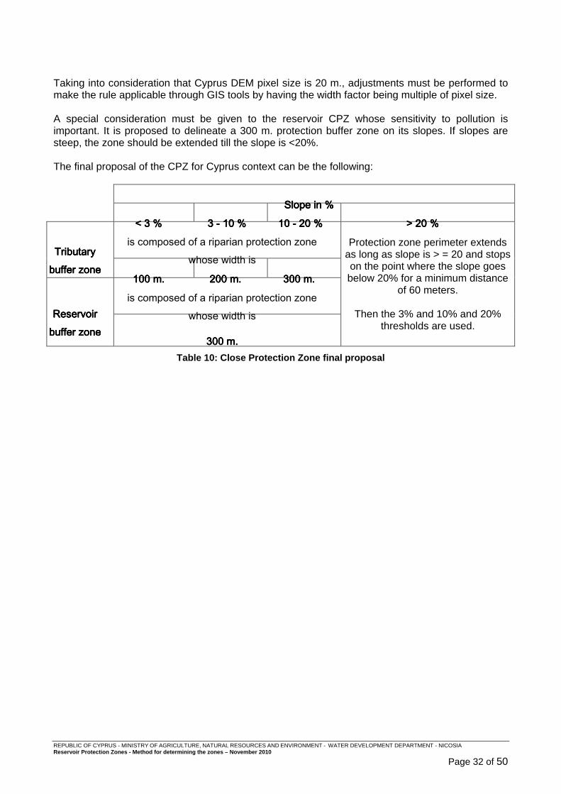
Taking into consideration that Cyprus DEM pixel size is 20 m., adjustments must be performed to make the rule applicable through GIS tools by having the width factor being multiple of pixel size. A special consideration must be given to the reservoir CPZ whose sensitivity to pollution is important. It is proposed to delineate a 300 m. protection buffer zone on its slopes. If slopes are steep, the zone should be extended till the slope is <20%. The final proposal of the CPZ for Cyprus context can be the following:
SlSlSlSlope in %ope in %ope in %ope in %
< 3< 3< 3< 3 %%%% 3333 ---- 10101010 %%%% 10101010 ---- 20202020 %%%% > 20> 20> 20> 20 %%%%
Tributary Tributary Tributary Tributary buffer zone buffer zone buffer zone buffer zone
is composed of a riparian protection zone whose width is
Protection zone perimeter extends as long as slope is > = 20 and stops on the point where the slope goes below 20% for a minimum distance
of 60 meters.
Then the 3% and 10% and 20% thresholds are used.
100100100100 m.m.m.m. 200 m.200 m.200 m.200 m. 333300000000 m.m.m.m.
Reservoir Reservoir Reservoir Reservoir buffer zone buffer zone buffer zone buffer zone
is composed of a riparian protection zone whose width is
333300000000 m.m.m.m. Table 10: Close Protection Zone final proposal

REPUBLIC OF CYPRUS - MINISTRY OF AGRICULTURE, NATURAL RESOURCES AND ENVIRONMENT - WATER DEVELOPMENT DEPARTMENT - NICOSIA Reservoir Protection Zones - Method for determining the zones – November 2010
Page 33 of 50
3. ANNEX – CPZ: GIS proposed application method for CPZ delineation
The above rules have been translated into a semi-automatic GIS delineation methodology. The GIS methodology has be developed by Kostas Aristeidou - Hydrologist at the Division of Hydrology & Hydrogeology - Water Development Department.
3.1. Data to be used
The following GIS data resources will be used:
o Satellite images of 2008 received from the Department of Lands and Surveys. In areas where there are clouds blocking the view the 2003 images received by the same Department will be used.
REPUBLIC OF CYPRUS - MINISTRY OF AGRICULTURE, NATURAL RESOURCES AND ENVIRONMENT - WATER DEVELOPMENT DEPARTMENT - NICOSIA Reservoir Protection Zones - Method for determining the zones – November 2010
Page 34 of 50
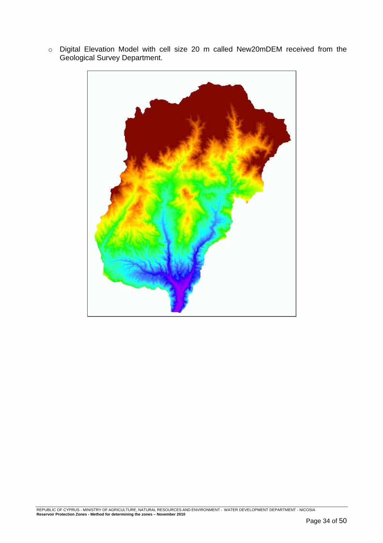
o Digital Elevation Model with cell size 20 m called New20mDEM received from the
Geological Survey Department.
REPUBLIC OF CYPRUS - MINISTRY OF AGRICULTURE, NATURAL RESOURCES AND ENVIRONMENT - WATER DEVELOPMENT DEPARTMENT - NICOSIA Reservoir Protection Zones - Method for determining the zones – November 2010
Page 35 of 50
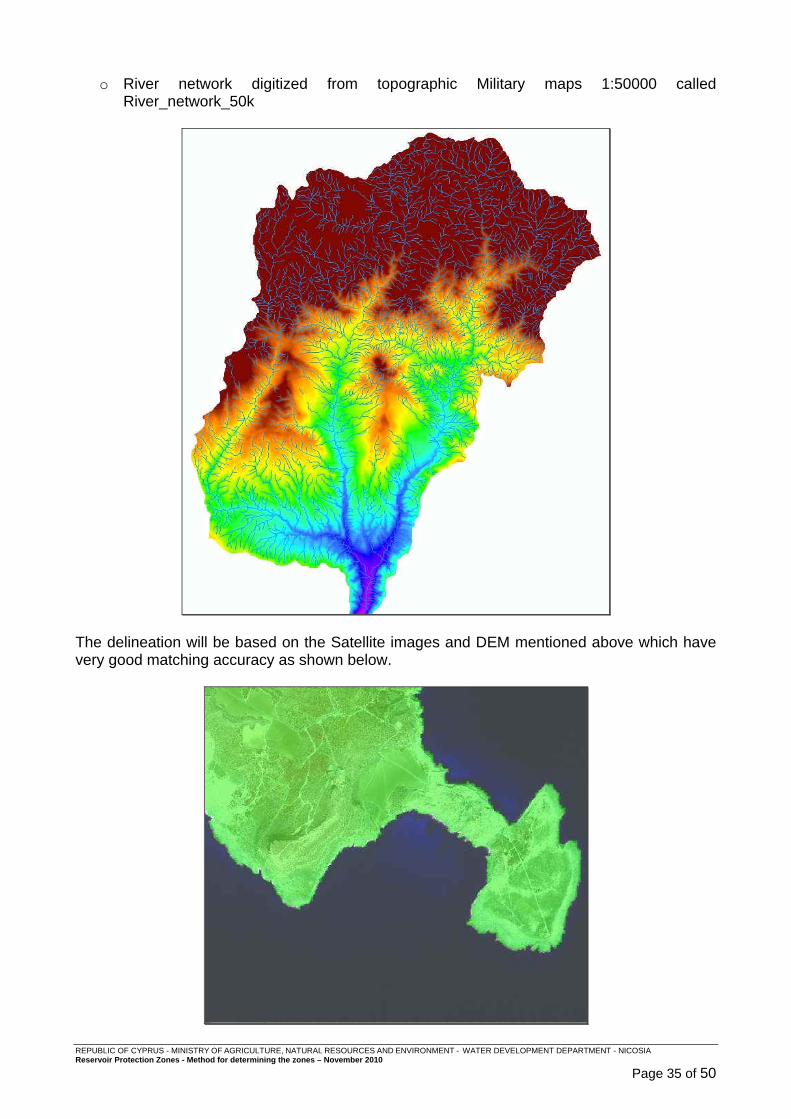
o River network digitized from topographic Military maps 1:50000 called River_network_50k
The delineation will be based on the Satellite images and DEM mentioned above which have very good matching accuracy as shown below.
REPUBLIC OF CYPRUS - MINISTRY OF AGRICULTURE, NATURAL RESOURCES AND ENVIRONMENT - WATER DEVELOPMENT DEPARTMENT - NICOSIA Reservoir Protection Zones - Method for determining the zones – November 2010
Page 36 of 50
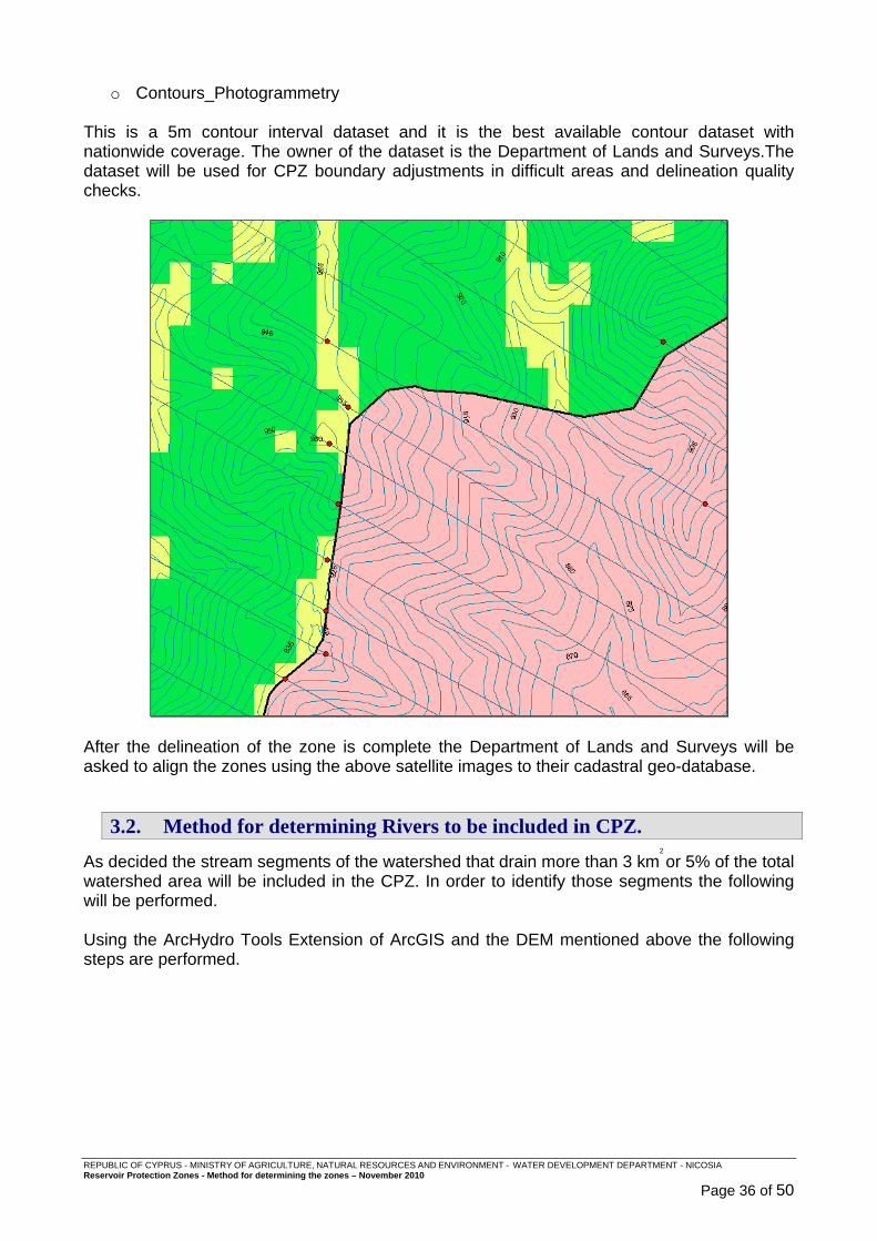
o Contours_Photogrammetry This is a 5m contour interval dataset and it is the best available contour dataset with nationwide coverage. The owner of the dataset is the Department of Lands and Surveys.The dataset will be used for CPZ boundary adjustments in difficult areas and delineation quality checks.
After the delineation of the zone is complete the Department of Lands and Surveys will be asked to align the zones using the above satellite images to their cadastral geo-database.
3.2. Method for determining Rivers to be included in CPZ.
As decided the stream segments of the watershed that drain more than 3 km2
or 5% of the total watershed area will be included in the CPZ. In order to identify those segments the following will be performed. Using the ArcHydro Tools Extension of ArcGIS and the DEM mentioned above the following steps are performed.
REPUBLIC OF CYPRUS - MINISTRY OF AGRICULTURE, NATURAL RESOURCES AND ENVIRONMENT - WATER DEVELOPMENT DEPARTMENT - NICOSIA Reservoir Protection Zones - Method for determining the zones – November 2010
Page 37 of 50
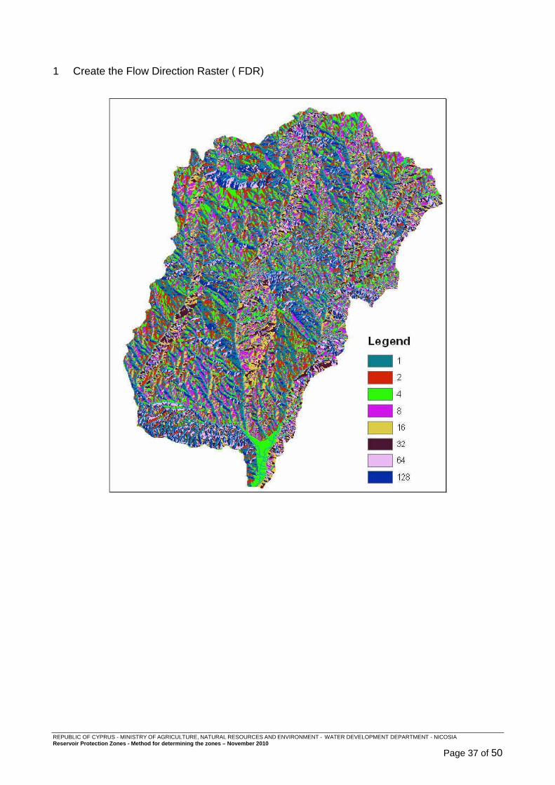
1 Create the Flow Direction Raster ( FDR)

REPUBLIC OF CYPRUS - MINISTRY OF AGRICULTURE, NATURAL RESOURCES AND ENVIRONMENT - WATER DEVELOPMENT DEPARTMENT - NICOSIA Reservoir Protection Zones - Method for determining the zones – November 2010
Page 38 of 50
2 Use Flow Direction Raster to create the Flow Accumulation Raster (FAC).
REPUBLIC OF CYPRUS - MINISTRY OF AGRICULTURE, NATURAL RESOURCES AND ENVIRONMENT - WATER DEVELOPMENT DEPARTMENT - NICOSIA Reservoir Protection Zones - Method for determining the zones – November 2010
Page 39 of 50
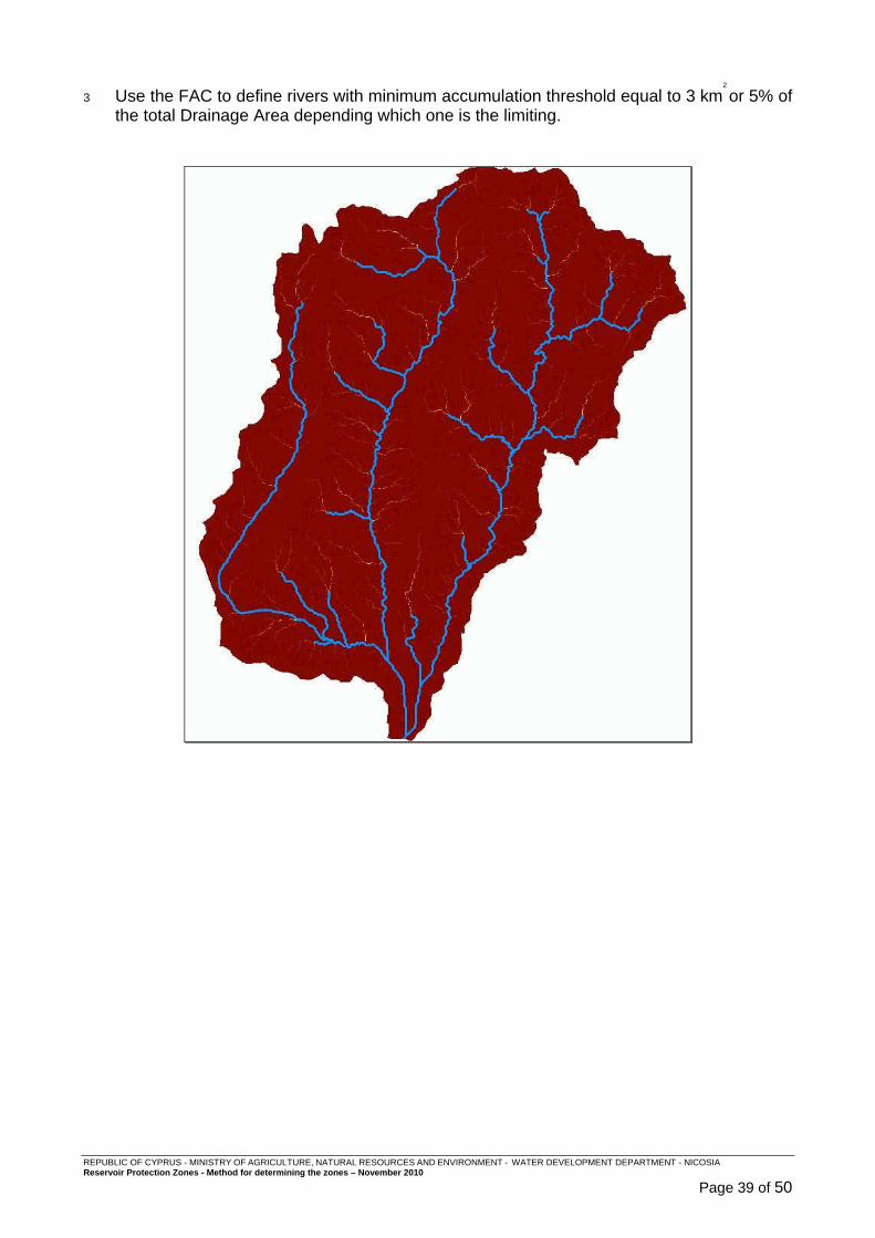
3 Use the FAC to define rivers with minimum accumulation threshold equal to 3 km2
or 5% of the total Drainage Area depending which one is the limiting.
REPUBLIC OF CYPRUS - MINISTRY OF AGRICULTURE, NATURAL RESOURCES AND ENVIRONMENT - WATER DEVELOPMENT DEPARTMENT - NICOSIA Reservoir Protection Zones - Method for determining the zones – November 2010
Page 40 of 50
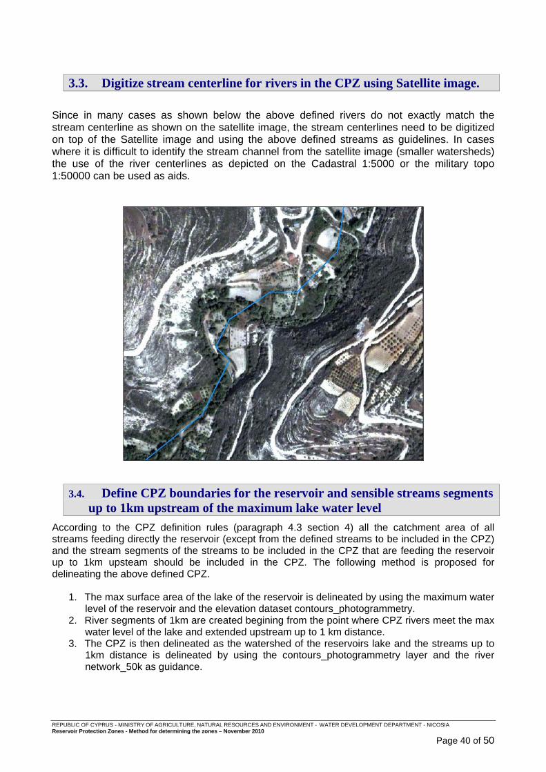
3.3. Digitize stream centerline for rivers in the CPZ using Satellite image.
Since in many cases as shown below the above defined rivers do not exactly match the stream centerline as shown on the satellite image, the stream centerlines need to be digitized on top of the Satellite image and using the above defined streams as guidelines. In cases where it is difficult to identify the stream channel from the satellite image (smaller watersheds) the use of the river centerlines as depicted on the Cadastral 1:5000 or the military topo 1:50000 can be used as aids.
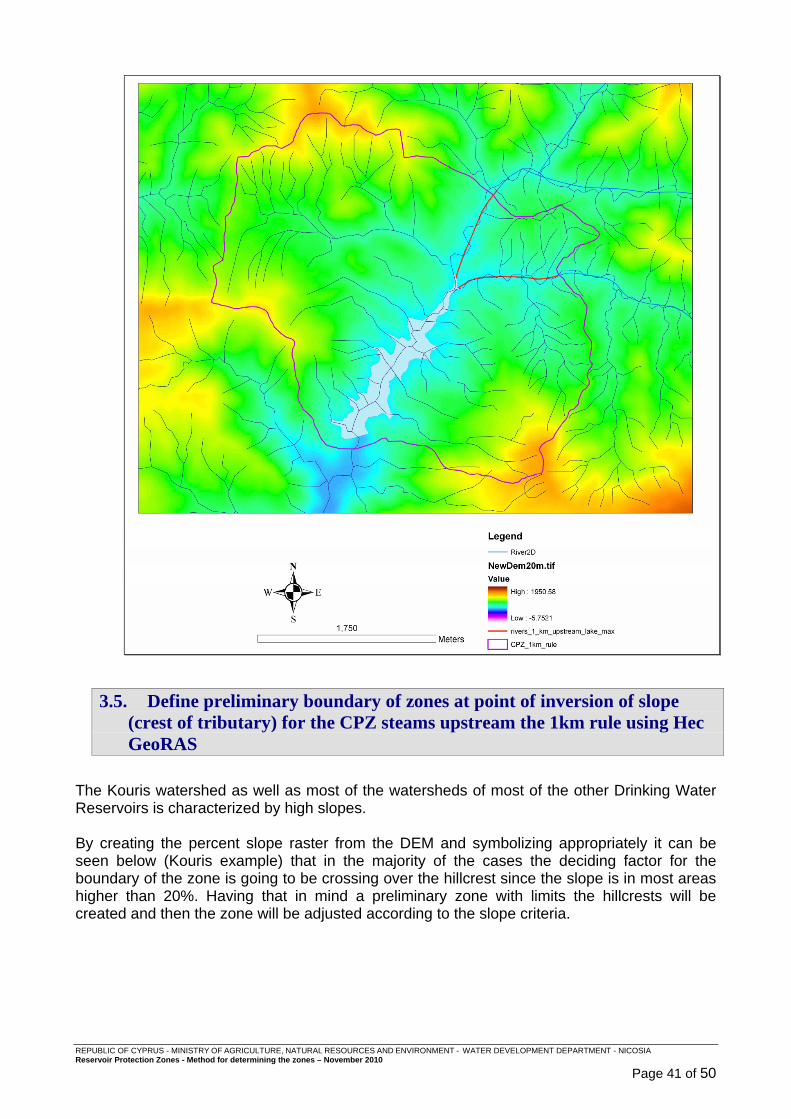
3.4. Define CPZ boundaries for the reservoir and sensible streams segments up to 1km upstream of the maximum lake water level
According to the CPZ definition rules (paragraph 4.3 section 4) all the catchment area of all streams feeding directly the reservoir (except from the defined streams to be included in the CPZ) and the stream segments of the streams to be included in the CPZ that are feeding the reservoir up to 1km upsteam should be included in the CPZ. The following method is proposed for delineating the above defined CPZ.
1. The max surface area of the lake of the reservoir is delineated by using the maximum water level of the reservoir and the elevation dataset contours_photogrammetry.
2. River segments of 1km are created begining from the point where CPZ rivers meet the max water level of the lake and extended upstream up to 1 km distance.
3. The CPZ is then delineated as the watershed of the reservoirs lake and the streams up to 1km distance is delineated by using the contours_photogrammetry layer and the river network_50k as guidance.
REPUBLIC OF CYPRUS - MINISTRY OF AGRICULTURE, NATURAL RESOURCES AND ENVIRONMENT - WATER DEVELOPMENT DEPARTMENT - NICOSIA Reservoir Protection Zones - Method for determining the zones – November 2010
Page 41 of 50
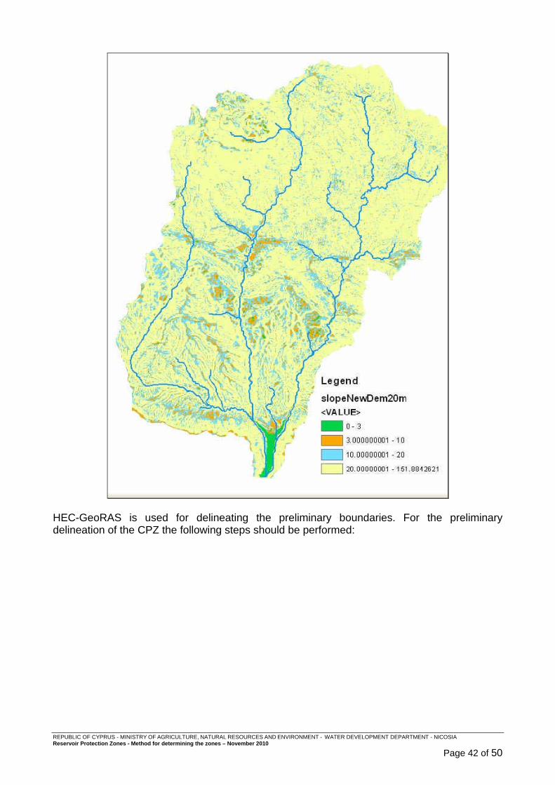
3.5. Define preliminary boundary of zones at point of inversion of slope (crest of tributary) for the CPZ steams upstream the 1km rule using Hec GeoRAS
The Kouris watershed as well as most of the watersheds of most of the other Drinking Water Reservoirs is characterized by high slopes. By creating the percent slope raster from the DEM and symbolizing appropriately it can be seen below (Kouris example) that in the majority of the cases the deciding factor for the boundary of the zone is going to be crossing over the hillcrest since the slope is in most areas higher than 20%. Having that in mind a preliminary zone with limits the hillcrests will be created and then the zone will be adjusted according to the slope criteria.
REPUBLIC OF CYPRUS - MINISTRY OF AGRICULTURE, NATURAL RESOURCES AND ENVIRONMENT - WATER DEVELOPMENT DEPARTMENT - NICOSIA Reservoir Protection Zones - Method for determining the zones – November 2010
Page 42 of 50
HEC-GeoRAS is used for delineating the preliminary boundaries. For the preliminary delineation of the CPZ the following steps should be performed:
REPUBLIC OF CYPRUS - MINISTRY OF AGRICULTURE, NATURAL RESOURCES AND ENVIRONMENT - WATER DEVELOPMENT DEPARTMENT - NICOSIA Reservoir Protection Zones - Method for determining the zones – November 2010
Page 43 of 50
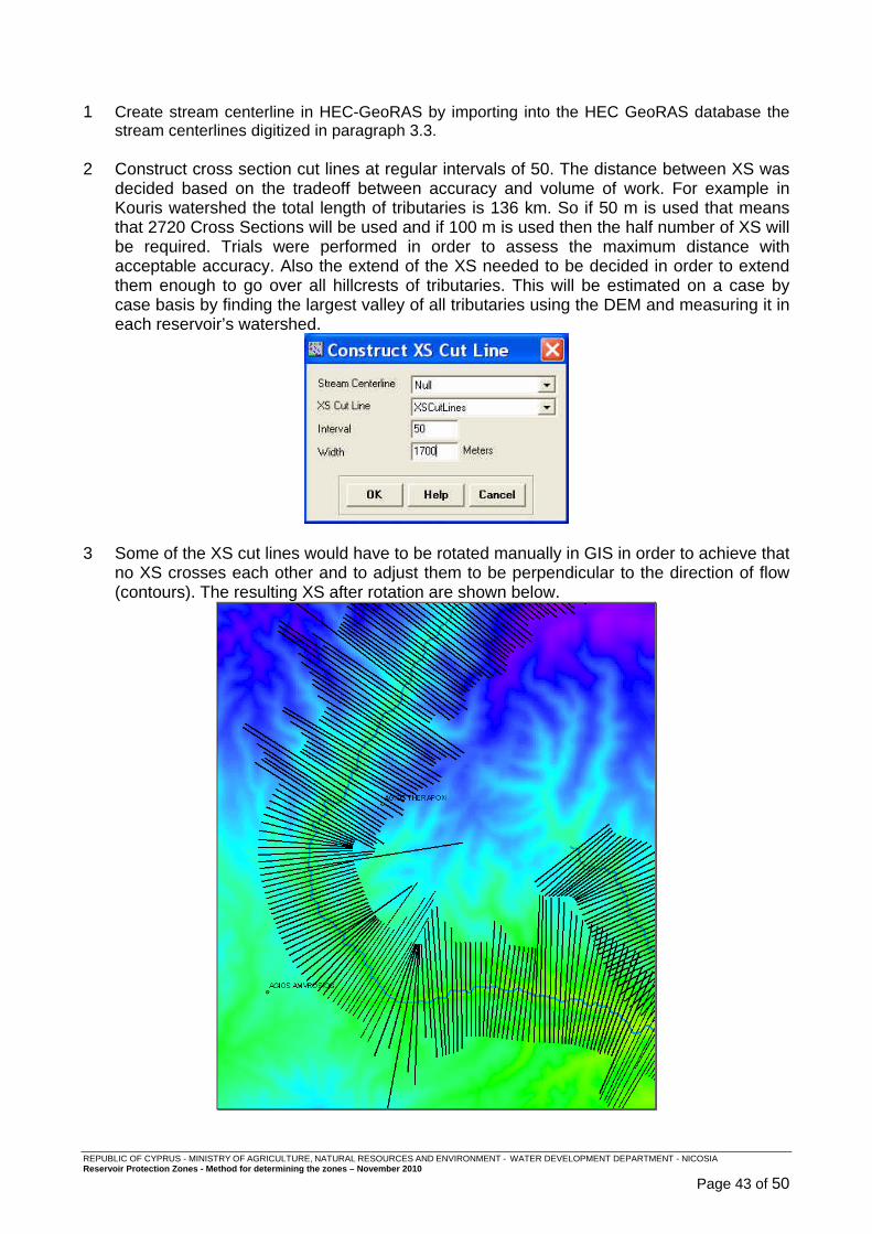
1 Create stream centerline in HEC-GeoRAS by importing into the HEC GeoRAS database the
stream centerlines digitized in paragraph 3.3. 2 Construct cross section cut lines at regular intervals of 50. The distance between XS was
decided based on the tradeoff between accuracy and volume of work. For example in Kouris watershed the total length of tributaries is 136 km. So if 50 m is used that means that 2720 Cross Sections will be used and if 100 m is used then the half number of XS will be required. Trials were performed in order to assess the maximum distance with acceptable accuracy. Also the extend of the XS needed to be decided in order to extend them enough to go over all hillcrests of tributaries. This will be estimated on a case by case basis by finding the largest valley of all tributaries using the DEM and measuring it in each reservoir’s watershed.
3 Some of the XS cut lines would have to be rotated manually in GIS in order to achieve that
no XS crosses each other and to adjust them to be perpendicular to the direction of flow (contours). The resulting XS after rotation are shown below.
REPUBLIC OF CYPRUS - MINISTRY OF AGRICULTURE, NATURAL RESOURCES AND ENVIRONMENT - WATER DEVELOPMENT DEPARTMENT - NICOSIA Reservoir Protection Zones - Method for determining the zones – November 2010
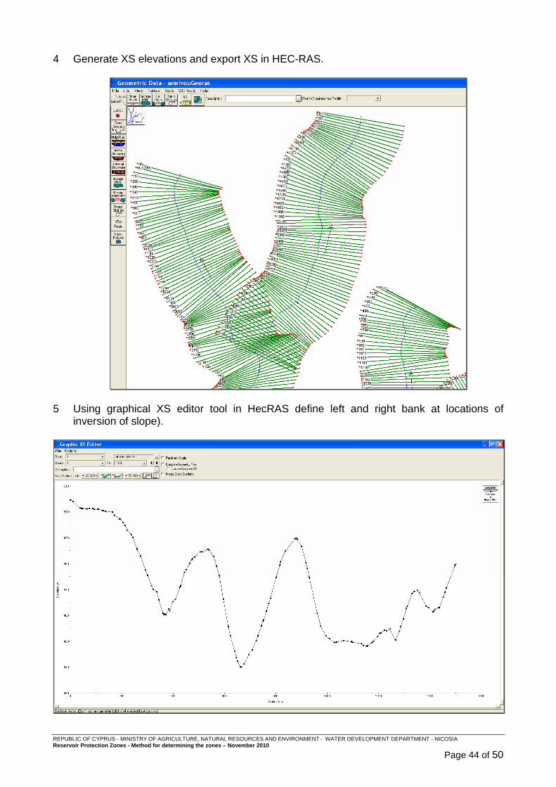
Page 44 of 50
4 Generate XS elevations and export XS in HEC-RAS.
5 Using graphical XS editor tool in HecRAS define left and right bank at locations of
inversion of slope).

REPUBLIC OF CYPRUS - MINISTRY OF AGRICULTURE, NATURAL RESOURCES AND ENVIRONMENT - WATER DEVELOPMENT DEPARTMENT - NICOSIA Reservoir Protection Zones - Method for determining the zones – November 2010
Page 45 of 50
The result of defining the bank stations in HEC-RAS is shown below:
6 Export XS from HEC-RAS back to ArcGIS.
REPUBLIC OF CYPRUS - MINISTRY OF AGRICULTURE, NATURAL RESOURCES AND ENVIRONMENT - WATER DEVELOPMENT DEPARTMENT - NICOSIA Reservoir Protection Zones - Method for determining the zones – November 2010
Page 46 of 50
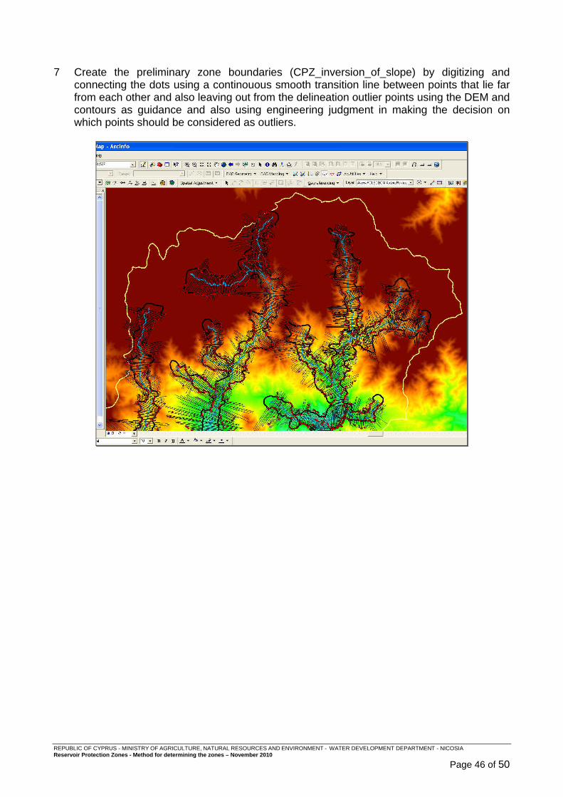
7 Create the preliminary zone boundaries (CPZ_inversion_of_slope) by digitizing and
connecting the dots using a continouous smooth transition line between points that lie far from each other and also leaving out from the delineation outlier points using the DEM and contours as guidance and also using engineering judgment in making the decision on which points should be considered as outliers.
REPUBLIC OF CYPRUS - MINISTRY OF AGRICULTURE, NATURAL RESOURCES AND ENVIRONMENT - WATER DEVELOPMENT DEPARTMENT - NICOSIA Reservoir Protection Zones - Method for determining the zones – November 2010
Page 47 of 50
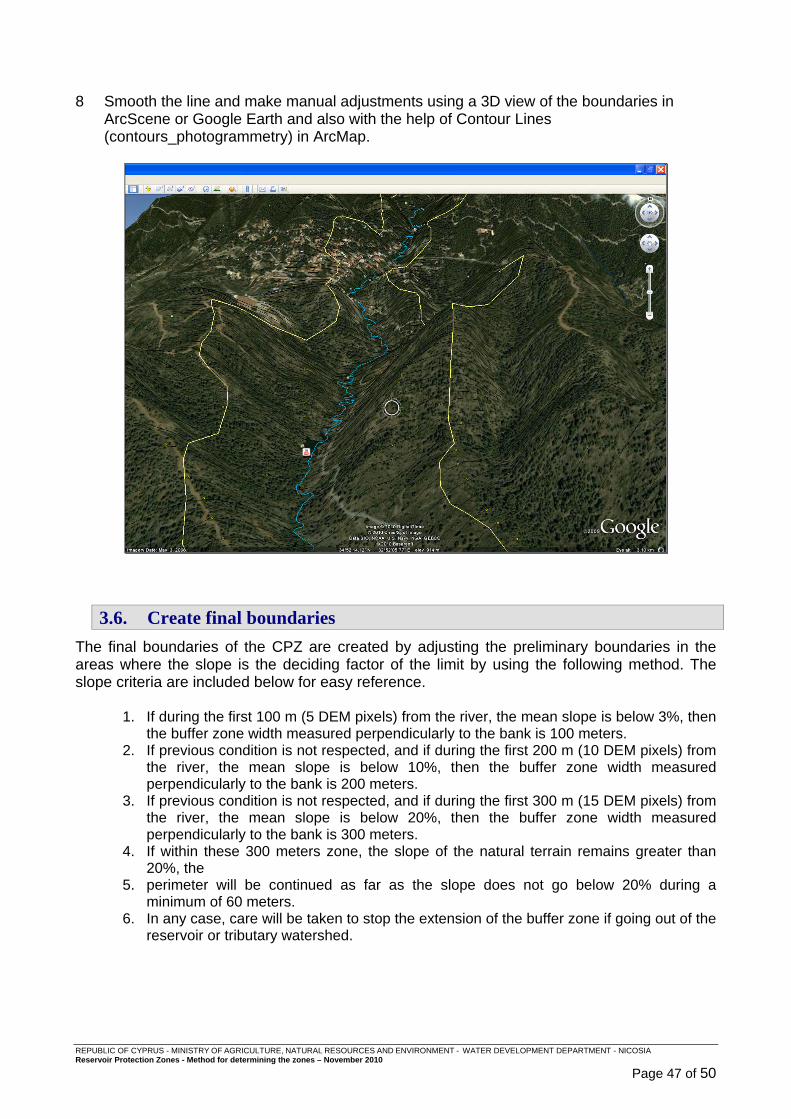
8 Smooth the line and make manual adjustments using a 3D view of the boundaries in
ArcScene or Google Earth and also with the help of Contour Lines (contours_photogrammetry) in ArcMap.
3.6. Create final boundaries
The final boundaries of the CPZ are created by adjusting the preliminary boundaries in the areas where the slope is the deciding factor of the limit by using the following method. The slope criteria are included below for easy reference.
1. If during the first 100 m (5 DEM pixels) from the river, the mean slope is below 3%, then the buffer zone width measured perpendicularly to the bank is 100 meters.
2. If previous condition is not respected, and if during the first 200 m (10 DEM pixels) from the river, the mean slope is below 10%, then the buffer zone width measured perpendicularly to the bank is 200 meters.
3. If previous condition is not respected, and if during the first 300 m (15 DEM pixels) from the river, the mean slope is below 20%, then the buffer zone width measured perpendicularly to the bank is 300 meters.
4. If within these 300 meters zone, the slope of the natural terrain remains greater than 20%, the
5. perimeter will be continued as far as the slope does not go below 20% during a minimum of 60 meters.
6. In any case, care will be taken to stop the extension of the buffer zone if going out of the reservoir or tributary watershed.
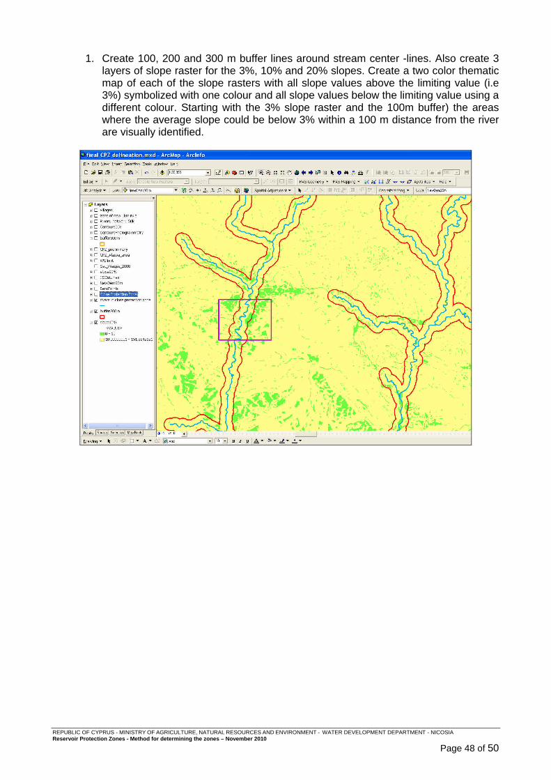
REPUBLIC OF CYPRUS - MINISTRY OF AGRICULTURE, NATURAL RESOURCES AND ENVIRONMENT - WATER DEVELOPMENT DEPARTMENT - NICOSIA Reservoir Protection Zones - Method for determining the zones – November 2010
Page 48 of 50
1. Create 100, 200 and 300 m buffer lines around stream center -lines. Also create 3 layers of slope raster for the 3%, 10% and 20% slopes. Create a two color thematic map of each of the slope rasters with all slope values above the limiting value (i.e 3%) symbolized with one colour and all slope values below the limiting value using a different colour. Starting with the 3% slope raster and the 100m buffer) the areas where the average slope could be below 3% within a 100 m distance from the river are visually identified.

REPUBLIC OF CYPRUS - MINISTRY OF AGRICULTURE, NATURAL RESOURCES AND ENVIRONMENT - WATER DEVELOPMENT DEPARTMENT - NICOSIA Reservoir Protection Zones - Method for determining the zones – November 2010
Page 49 of 50
2. If the preliminary CPZ boundary extends outside the slope limit buffer line in the
area of the limiting slope factor then the CPZ boundary is manually adjusted so that the CPZ line overlaps with the buffer line. The resulting CPZ is named CPZ_slope3 in the geodatabase.
Steps 1 and 2 are repeated for the 10% slope and 200m buffer and finally for the 20% slope and 300m buffer. The resulting CPZ’s are named CPZ_slope10 and CPZ_slope20 respectively. In cases where the decision if the mean slope is above or below the limits not clear the slope can be measured on the XS in Hec RAS as shown below.
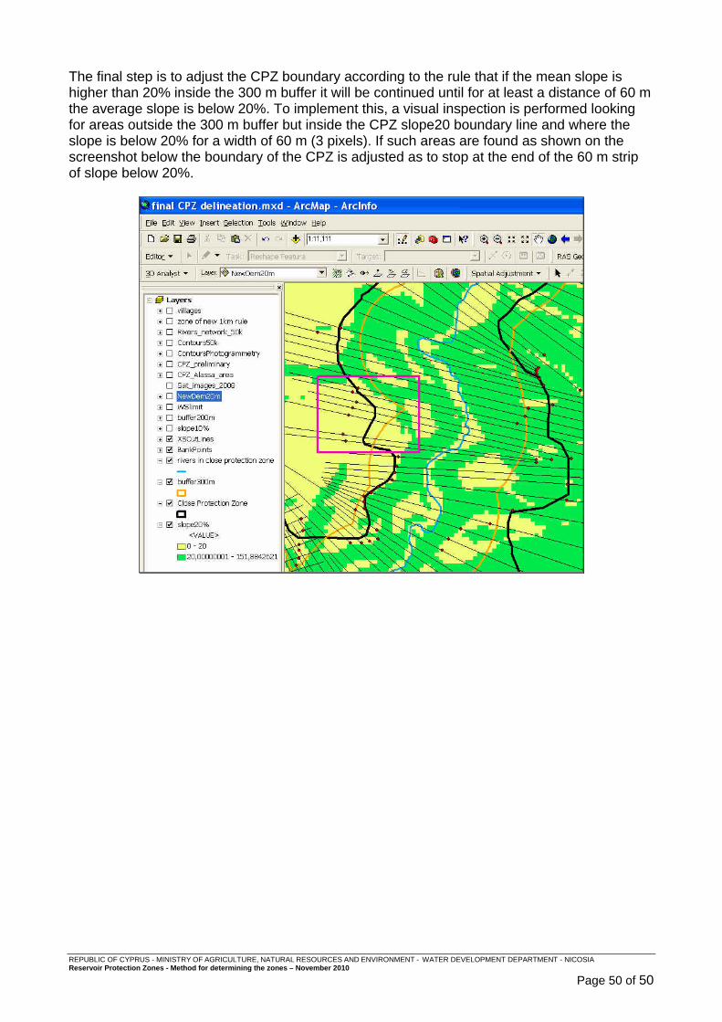
REPUBLIC OF CYPRUS - MINISTRY OF AGRICULTURE, NATURAL RESOURCES AND ENVIRONMENT - WATER DEVELOPMENT DEPARTMENT - NICOSIA Reservoir Protection Zones - Method for determining the zones – November 2010
Page 50 of 50
The final step is to adjust the CPZ boundary according to the rule that if the mean slope is higher than 20% inside the 300 m buffer it will be continued until for at least a distance of 60 m the average slope is below 20%. To implement this, a visual inspection is performed looking for areas outside the 300 m buffer but inside the CPZ slope20 boundary line and where the slope is below 20% for a width of 60 m (3 pixels). If such areas are found as shown on the screenshot below the boundary of the CPZ is adjusted as to stop at the end of the 60 m strip of slope below 20%.