reservoir to surface link - petroleumengineers.ru · reservoir to surface link reference manual...
TRANSCRIPT

Reservoir to Surface Link
Reference Manual
2010.1
Proprietary noticeCopyright © 2010 Schlumberger. All rights reserved. Reproduction or alteration without prior written permission is prohibited, except asallowed under applicable law.
Use of this product is governed by the License Agreement. Schlumberger makes no warranties, express, implied, or statutory, with respectto the product described herein and disclaims without limitations any warranties of merchantability or fitness for a particular purpose.
Trademarks & service marks"Schlumberger," the Schlumberger logotype, and other words or symbols used to identify the products and services described herein areeither trademarks, trade names, or service marks of Schlumberger and its licensors, or are the property of their respective owners. Thesemarks may not be copied, imitated, or used, in whole or in part, without the express prior written permission of their owners. In addition,covers, page headers, custom graphics, icons, and other design elements may be service marks, trademarks, and/or trade dress ofSchlumberger and may not be copied, imitated, or used, in whole or in part, without the express prior written permission of Schlumberger.

Reservoir to Surface Link Reference Manual Contents
3
ContentsList of Figures ..... ...................................................................................................................................................................7List of Tables ...... ...................................................................................................................................................................8
Chapter 1 - New Developments ....................................................................................................... 9New Developments for 2010.1 ...............................................................................................................................................9New Developments for 2009.1 .............................................................................................................................................10New Developments for 2008.1A...........................................................................................................................................11New Developments for 2008.1 .............................................................................................................................................12New Developments for 2007.1 .............................................................................................................................................13New Developments for 2006.1 .............................................................................................................................................14
Chapter 2 - Data file overview........................................................................................................ 17Overview............. .................................................................................................................................................................17Data file sections .................................................................................................................................................................18Data file structure .................................................................................................................................................................19Global keywords . .................................................................................................................................................................21RUNSPEC section overview.................................................................................................................................................23PROPS section overview......................................................................................................................................................24SUMMARY section overview................................................................................................................................................26SCHEDULE section overview...............................................................................................................................................31
Chapter 3 - Introduction ................................................................................................................. 33What is Reservoir to Surface Link? ......................................................................................................................................33
Chapter 4 - Using R2SL.................................................................................................................. 35Introduction......... .................................................................................................................................................................35Coupling a single reservoir simulation to a production network............................................................................................36Coupling multiple reservoir simulations through common production or injection group control ..........................................39Coupling multiple reservoir simulations to surface facility networks: ....................................................................................43Coupling multiple reservoir simulations to surface facility networks .....................................................................................47
Chapter 5 - Keywords ..................................................................................................................... 57ACF: Acentric factor ............................................................................................................................................................. 57BIC: Binary interaction coefficients ..................................................................................................................................... 58CNAMES: Component names ............................................................................................................................................... 59COMPOPEN: Shuts or opens completions ............................................................................................................................. 60COMPDIMS: Compositional coupled simulation dimensions................................................................................................. 61CONDLIST: Sets condition for list membership ................................................................................................................... 62CONDWHEN: Condition for field events handling ................................................................................................................... 69COUPLOCA: Sets coupling location for a well ....................................................................................................................... 74DATES: Advances all coupled simulations to specified report date(s) ................................................................................. 75DFLTNET: Assigns a default network task ........................................................................................................................... 76DFLTRES: Assigns a default reservoir task.......................................................................................................................... 77ECHO: Switches echo output on........................................................................................................................................... 78END: Logical end of input file ............................................................................................................................................... 79ENDFLUID: End of a fluid definition ..................................................................................................................................... 80ENDINC: Logical end of include file ..................................................................................................................................... 81ENDWHEN: End the set of keywords following a WHEN keyword......................................................................................... 82EOS: Specify which equation of state is to be used ............................................................................................................. 83FEDIMS: Field events functionality dimensions ................................................................................................................... 84FLUID: Fluid definition......................................................................................................................................................... 85GCONEXTN: Control group rate by external network automatic chokes ............................................................................... 86
4 Reservoir to Surface Link Reference ManualContents
GCONINJE: Injection rate controls or limits for groups......................................................................................................... 88GCONPROD: Production rate controls or limits for groups ..................................................................................................... 91GGASQUAL: Assign a gas quality or calorific value target to a reservoir coupling global group ........................................... 94GINJGAS: Specify the nature of the injected gas in a group................................................................................................ 95GLIFTLIM: Maximum group capacity for artificial lift........................................................................................................... 96GLIFTOPT: Group lift gas limits for gas lift optimization ...................................................................................................... 97GMASTIGR: Injection guide rates for master groups ............................................................................................................ 98GMASTPGR: Production guide rates for master groups ...................................................................................................... 100GMFVD: Stock tank gas mole fraction with respect to surface oil density table .................................................................. 102GRFORMS: Guide rate formulae .......................................................................................................................................... 103GRUPIRT: Set group injection rate target or limit ............................................................................................................... 107GRUPMAST: Identify master groups and corresponding slave groups................................................................................ 108GRUPPRT: Set group production rate target or limit ........................................................................................................... 110GRUPTARG: Resets a group production rate target or limit ................................................................................................ 111GRUPTREE: Sets up group tree structure for group control ................................................................................................ 113GUIDERAT: Specify general formula for guide rates.......................................................................................................... 114INCLUDE: Include the contents of another named file....................................................................................................... 118KVALUES: Use K-values for liquid-vapor phase equilibrium .............................................................................................. 119KVTDIMS: K-values table dimensions................................................................................................................................ 120KVTABLE: K-values versus pressure table ........................................................................................................................ 121LIST: Sets up a static or dynamic list of wells, groups, nodes or branches...................................................................... 122LUTABGEN: Request the generation of Lookup tables for each well in the simulation....................................................... 127MAPBNODS: Map reservoir or network boundary nodes ..................................................................................................... 128MAXNBALE: Maximum network balancing error for network boundary nodes at end of time step ..................................... 130MESLEVEL: Messages level from a task ............................................................................................................................ 131MESSAGES: Resets message print and stop limits............................................................................................................. 132MFVPDDIM: Vapor or liquid mole fraction versus pressure or density table dimensions.................................................... 134MINTSNBE: Minimum length for controller time step restricted by network balancing error .............................................. 135MW: Molecular weights........................................................................................................................................................ 136NCOMPS: Number of components....................................................................................................................................... 137NETBALC: Network balancing calculation instructions ....................................................................................................... 138NETBCONF: Modifies the branch configuration of the network ........................................................................................... 144NETBOPEN: Activate or deactivate a network branch......................................................................................................... 145NETCHOKE: Modifies the conditions of a physical network choke...................................................................................... 146NETCMPRS: Modifies the conditions of a network compressor........................................................................................... 148NETDEBUG: Set network debugging level for a network task ............................................................................................. 150NETGLIFT: Modifies gas lift conditions on a network branch ............................................................................................ 151NETLIMIT: Sets or modifies a rate limit using an automatic choke on a network branch................................................. 153NETPUMP: Modifies the conditions of a network pump....................................................................................................... 156NETTYPE: Specify network type......................................................................................................................................... 158NINJGAS: Specifies the nature of the injected gas in a network node .............................................................................. 159NOECHO: Disable echoing of the input file .......................................................................................................................... 161NSINKBO: Sets or modifies sink node conditions in a black oil network ............................................................................ 162NSINKCO: Sets or modifies sink node conditions in a compositional gas injection network .............................................. 164NSOURCBO: Sets or modifies source node conditions in a black oil network ..................................................................... 166NSOURCCO: Sets or modifies source node conditions in a compositional network ............................................................ 169OBEYECL: Changes the network balancing setting for the OBEY ECLIPSE coupling method. ......................................... 171OMEGAA: Overrides default Ωa values ............................................................................................................................... 173OMEGAB: Overrides default Ωb values ............................................................................................................................... 174OMFVD: Stock tank oil mole fraction with respect to surface oil density table .................................................................... 175OPTIONSM: Activates special program options.................................................................................................................. 176PCRIT: Critical pressures .................................................................................................................................................. 178PRCORR: Request modified Peng-Robinson EoS .............................................................................................................. 179RCMASTS: Minimum length for controller time step restricted by flow change ................................................................... 180RESBNODS: Specify reservoir boundary nodes as wells or well-groups............................................................................. 181RPTOPTS: Set options for HTML reports............................................................................................................................ 182RPTSCHED: Controls on output from SCHEDULE section ................................................................................................. 183RUNMODE: General information about the run .................................................................................................................... 184SEGCTRL: Control items in a well segment of a multi-segmented well .............................................................................. 186

Reservoir to Surface Link Reference Manual Contents
5
SEPCOND: Introduce a new separator condition stage....................................................................................................... 187SETFLUID: Associates a FLUID to a task, group, well, completion or node ..................................................................... 189SETSEP: Associates a separator to a task, well, group, or node ....................................................................................... 190SPLITTAB: Split parameters table .................................................................................................................................... 191SSHIFT: Equation of state shift parameters ...................................................................................................................... 192START: Specifies a start date ............................................................................................................................................ 193SUMOPTS: Set options for Summary files........................................................................................................................... 194SYNCSTEP: Upper limit on the synchronization step for reservoir coupling....................................................................... 195TASKDIMS: Maximum dimensions for memory allocation ................................................................................................. 196TCRIT: Critical temperatures............................................................................................................................................. 197TASKSPEC: General information about each task ............................................................................................................. 198TITLE: Specify run title ..................................................................................................................................................... 201TSTEP: Advances all coupled simulations over specified time interval(s) ......................................................................... 202UNITS: Unit convention for data input or output ................................................................................................................ 203VCRIT: Critical volumes..................................................................................................................................................... 204WATERBAL: Specify water balancing method .................................................................................................................... 205WCONINJE: Control data for injection wells ....................................................................................................................... 206WCONPROD: Control data for production wells.................................................................................................................... 208WEFAC: Efficiency factor for well’s contribution to flow in the network ............................................................................... 210WELLBHT: Wells bottom hole temperature for network boundary nodes setting ............................................................... 212WELLGRUP: Assigns a well to a group ............................................................................................................................... 213WELLSTRE: Set composition of injection gas stream......................................................................................................... 214WELLTHT: Wells tubing head temperature for network boundary nodes setting ............................................................... 215WELOPEN: Shuts or re-opens wells .................................................................................................................................... 216WELTARG: Resets a well operating target or limit .............................................................................................................. 217WHEN: Initiates a set of keywords to be processed when a set of conditions are satisfied ................................................ 218WLIFTOPT: Sets well artificial lift options........................................................................................................................... 228WNETDP: Additional pressure drop between network node and well ................................................................................. 229WRITEDBG: Output debug information............................................................................................................................... 230WTMULT: Multiplies a well operating target or limit............................................................................................................. 231XMFVP: Liquid mole fraction with respect to pressure table............................................................................................... 232XMFVRS: Liquid mole fraction with respect to the liquid phase gas to oil ratio table .......................................................... 234YMFVP: Vapor mole fraction with respect to pressure table............................................................................................... 236YMFVRV: Vapor mole fraction with respect to the vapor phase oil to gas ratio table ......................................................... 238ZCRIT: Critical Z-factors.................................................................................................................................................... 240
Chapter 6 - Lookup Table Module ............................................................................................... 241What is the Lookup Table module? ....................................................................................................................................241Data file overview ...............................................................................................................................................................242DATES: Advances the lookup table module to specified report date(s) ............................................................................. 247ECHO: Switches echo output on......................................................................................................................................... 248END: Logical end of input file ............................................................................................................................................. 249ENDINC: Logical end of include file ................................................................................................................................... 250INCLUDE: Include the contents of another named file....................................................................................................... 251LOOKUP: Specifies a Lookup Table definition .................................................................................................................... 252MESSAGES: Resets message print and stop limits............................................................................................................. 256NOECHO: Disable echoing of the input file.......................................................................................................................... 258START: Specifies a start date ............................................................................................................................................ 259TABDIMS: Maximum dimensions for memory allocation ................................................................................................... 260TITLE: Specify run title ..................................................................................................................................................... 261TSTEP: Advance the lookup table module over specified time interval(s) ......................................................................... 262UNITS: Unit convention for data input/output .................................................................................................................... 263WCONPROD: Control data for production wells.................................................................................................................... 264WELOPEN: Shuts or re-opens wells .................................................................................................................................... 265WELSPECS: General specification data for wells................................................................................................................ 266WRITEDBG: Output debug information............................................................................................................................... 267

6 Reservoir to Surface Link Reference ManualContents
Chapter 7 - The Black Oil Tank Model......................................................................................... 269Introduction ......... ...............................................................................................................................................................269Data file overview ...............................................................................................................................................................270Using the Tank Model .........................................................................................................................................................278AQUIFER: Aquifer properties ............................................................................................................................................. 282BWREF: Reference water formation volume factor ............................................................................................................. 284CONTINIT: Initial phase contact depths ............................................................................................................................ 285CR: Reservoir rock compressibility..................................................................................................................................... 286CW: Reservoir water compressibility................................................................................................................................... 287DATES: Advance simulation to specified dates.................................................................................................................. 288DPMAX: Maximum pressure change................................................................................................................................... 289DRYGAS: Dry gas reservoir................................................................................................................................................. 290DTMAX: Maximum time change.......................................................................................................................................... 291ECHO: Switches echo output on ......................................................................................................................................... 292END: Logical end of input file.............................................................................................................................................. 293ENDINC: Logical end of include file.................................................................................................................................... 294FIELD: Field units.............................................................................................................................................................. 295FIPINIT: Initial fluids in place........................................................................................................................................... 296GASSG: Gas specific gravity ............................................................................................................................................... 297GFVFCORR: Gas formation volume factor correlation method............................................................................................ 298INCLUDE: Include the contents of another named file....................................................................................................... 299INITCOND: Initial conditions .............................................................................................................................................. 300LIVEOIL: Live oil reservoir................................................................................................................................................ 301MBALDAKE: Dake material balance method....................................................................................................................... 302MBALFPT: FPT material balance method........................................................................................................................... 303MBERRMAX: Maximum material balance error .................................................................................................................... 304METRIC: Metric units.......................................................................................................................................................... 305NOECHO: Disable echoing of the input file .......................................................................................................................... 306NTG: Reservoir net to gross thickness ratio ....................................................................................................................... 307OILAPI: Oil API................................................................................................................................................................. 308OFVFCORR: Oil formation volume factor correlation method.............................................................................................. 309PBRSCORR: Bubble point pressure and solution gas-oil ratio correlation method.............................................................. 310PERM: Reservoir permeability ............................................................................................................................................ 311PORO: Reservoir porosity ................................................................................................................................................... 312PVTTAB: PVT tabular data ................................................................................................................................................. 313PVTTABDG: PVT gas-water tabular data............................................................................................................................ 315PVTINT: PVT internal correlation pressure controls.......................................................................................................... 317REPORT: Report options..................................................................................................................................................... 318RESCYL: Cylindrical reservoir geometry ............................................................................................................................ 319RESVOL: Reservoir area versus depth............................................................................................................................... 320SGRW: Reservoir residual gas saturation to water.............................................................................................................. 321SORG: Reservoir residual oil saturation to gas ................................................................................................................... 322SORW: Reservoir residual oil saturation to water ................................................................................................................ 323START: Simulation start date ............................................................................................................................................. 324SWC: Reservoir connate water saturation........................................................................................................................... 325TIME: Advance simulation to specified times .................................................................................................................... 326TITLE: Simulation title....................................................................................................................................................... 327TSTEP: Advance simulation by specified time steps.......................................................................................................... 328WELLS: Well data ............................................................................................................................................................... 329ZFACCORR: Gas Z-factor correlation method..................................................................................................................... 333
Chapter 8 - Limitations and restrictions ..................................................................................... 335Introduction ......... ...............................................................................................................................................................335Current restrictions..............................................................................................................................................................336Current limitations...............................................................................................................................................................339
Appendix A - Index ....................................................................................................................... 341

Reservoir to Surface Link Reference Manual List of Figures
7
List of FiguresFigure 5.1 .......... The implementation of an automatic choke on a network branch ........................................................154

8 Reservoir to Surface Link Reference ManualList of Tables
List of TablesTable 2.1 Data file sections......................................................................................................................................18Table 2.2 Global keywords ......................................................................................................................................22Table 2.3 RUNSPEC keywords ...............................................................................................................................23Table 2.4 PROPS keywords ....................................................................................................................................24Table 2.5 SUMMARY keywords ..............................................................................................................................26Table 2.6 Wells and Groups SUMMARY output control ..........................................................................................26Table 2.7 Nodes SUMMARY output control ............................................................................................................29Table 2.8 Branch (PIPE) SUMMARY output control ................................................................................................29Table 2.9 Task SUMMARY output control ...............................................................................................................30Table 2.10 SCHEDULE keywords .............................................................................................................................31Table 5.1 Well, group and branch mnemonics that can be used in a condition for list membership. ......................63Table 5.2 Branch mnemonics that can be used in a condition for list membership .................................................64Table 5.3 Node mnemonics that can be used in a condition for a list membership .................................................66Table 5.4 Time mnemonics that can be used in a condition within the keyword CONDWHEN. ..................................70Table 5.5 RPTSCHED output controls...................................................................................................................183Table 6.1 Lookup Data file sections.......................................................................................................................242Table 6.2 Lookup Global keywords........................................................................................................................245Table 6.3 Lookup RUNSPEC keywords ................................................................................................................245Table 6.4 Lookup SCHEDULE keywords ..............................................................................................................246Table 7.1 Tank Model Data file sections................................................................................................................270Table 7.2 Global Tank Model keywords.................................................................................................................272Table 7.3 Tank Model RUNSPEC keywords..........................................................................................................273Table 7.4 Tank Model PROPS keywords ..............................................................................................................273Table 7.5 Wells and Groups Output Summary Vector ...........................................................................................274Table 7.6 Tank Model SCHEDULE keywords........................................................................................................277

Reservoir to Surface Link Reference Manual New DevelopmentsNew Developments for 2010.1
9
Chapter 1New Developments
New Developments for 2010.1• The default coupling method is now FPI.
• The functionality implemented by the DISTRIB keyword is now the default and this has removed the necessity for a separate keyword.
• You can now suppress additional network balances when they may not be needed.
• There are now additional options to handle the transfer of water from ECLIPSE to PIPESIM using the new WATERBAL keyword.
• Timing information is added to the debug file and as Summary Vectors.
• There are additional group, well and completion Summary Vectors.
• The default behavior for stopping the coupled run has been changed such that the simulation will continue if one or more reservoirs stops running, and will only stop if all reservoirs have stopped.
• A range of alternative well and network solve actions following an event have been added. This includes triggering of an IAM solve.
• GRUPTARG has been implemented.
• SPIN communication has been added as a speedup option.
• Additional variables have been added to the lookup table model to enable blackoil delumping.
• Gas SG is now allowed in the NETGLIFT keyword.
• Additional options are now available for passing the temperature between the reservoir and surface models.
• Lookup Tables now support tubing head coupling.
• Tubing Head IPR calculations are automatically invoked for TH coupled wells.
• Wells shut in during Obey-Eclipse coupling can now be reopened after a defined length of time has elapsed.
10 New Developments Reservoir to Surface Link Reference ManualNew Developments for 2009.1
New Developments for 2009.1• Support for Multi Segmented Wells.
• Increased accuracy of phase handling when transferring produced water between ECLIPSE and PIPESIM.
• Enhanced interaction with the ECLIPSE drilling queue logic.
• Additional debug for troubleshooting large models.
• Support for PIPESIM's Wells Offline (WOFL) mode.
This enables wells to be run outside of the general network solver, and to be parameterized as curves, to increase stability and reduce simulation time.
• Ability to delay the actioning of a rule until a certain number of days after a condition is satisfied.
• Support for Intel MPI.
• Functionality to reopen unstable wells which have previously been shut in.
• Extended the WELOPEN functionality to act on completions.
• Version number reporting to DBG file.
• Methanol handling to allow for modeling of hydrate suppression.
• Temperature passing between R2SL and PIPESIM.
• Maximum number of slave processes increased from 20 to 100.

Reservoir to Surface Link Reference Manual New DevelopmentsNew Developments for 2008.1A
11
New Developments for 2008.1A• Use of the Full IPR balancing method to more accurately model the well inflow
performance when using the FPI option.
• Handling of water between ECLIPSE and PIPESIM has been streamlined.
• Significant readability enhancements to the DBG file to enable detailed analysis of balancing algorithms.
• Significant enhancements to the Obey-ECLIPSE balancing method.
• Improved coupling with networks containing unstable and non-flowing wells.

12 New Developments Reservoir to Surface Link Reference ManualNew Developments for 2008.1
New Developments for 2008.1• The OBEYECL coupling method has been significantly enhanced to provide accelerated
convergence and intelligence to deal with wells operating in their unstable region.
• A fully featured coupling with CMG’s IMEX reservoir simulator has been developed.
• Significant Performance improvements over previous releases of R2SL
• Addition of the DISTRIB keyword which allows multiple ECLIPSE models to step through time simultaneously rather than sequentially, which can significantly reduce overall run times.
• Improved time step selection in ECLIPSE when running under R2SL.
• Improved coupling with networks containing unstable and non-flowing wells.
• Improved reproducibility of results for diagnostic purposes when running with PIPESIM.
• Date and version stamps are now output to the R2SL PRT file.

Reservoir to Surface Link Reference Manual New DevelopmentsNew Developments for 2007.1
13
New Developments for 2007.1• Changes have been made to the network balancing option. A new keyword OBEYECL has
been introduced. This keyword sets of modifies the OBEYECL network balancing settings for individual wells. The keyword must be used in conjunction with the OBEYECL coupling mode. This option is selected by setting item 10 of NETBALC to OBEY.

14 New Developments Reservoir to Surface Link Reference ManualNew Developments for 2006.1
New Developments for 2006.1
New functionality
Completion level events and reportingThe 2005A R2SL release contained optional functionality to allow delumping to be performed at the completion level. Completion level functionality has been extended to allow completion level reporting and well management events.
A completion report is now available in the HTML reports, in the PRT file and by selecting completion summary vectors.
Completions lists may be created. Dynamic lists and field event conditions may be controlled using completion summary vector quantities (e.g. completion water cut). Finally, completions may opened or close using the new COMPOPEN keyword.
Note In order to make use of this functionality, OPTIONSM item 15 must be activated.
Gas calorific value controlIn gas field operations, it is often required to impose both a gas handling limit and a gas quality target on a field. This keyword permits a gas quality or gas calorific value to be imposed on a global reservoir coupling group.
The following model requirements must be met to use this feature:
1 A production gas rate limit is imposed on the same group as the gas quality target
2 There must be at least two groups feeding the group on which the gas quality target is imposed
3 The actual gas qualities of the two groups must span the required target
4 No network should be coupled to the system.
Please refer to "Gas Calorific Value Control" in the "ECLIPSE Technical Description" for further information on the algorithm used to allocate production to the groups subordinate to the gas quality controlled group.
Behavioral changes
Network balancing The network balancing algorithm has been improved by providing a new method of network coupling. The method involves the following steps:
1 Well PI queried from the ECLIPSE well model
2 Boundary conditions transferred to the network wells.
3 The network solves for pressure and rate.
Reservoir to Surface Link Reference Manual New DevelopmentsNew Developments for 2006.1
15
4 Network flow rates passed to reservoir.
5 The reservoir then proceeds to the next timestep using the network flow rates as the coupling constraint.
The PI from the ECLIPSE well model may be one of:
1 Linear IPR based on calculation at Peaceman Radius in well connection grid blocks
2 Linear IPR based on a 9 point average reservoir pressure and inflow PI.
Option 1 gives a less representative IPR, but is available for black oil (oil-/water-/gas-based boundary conditions) and compositional (mass-/composition-based boundary conditions) reservoirs. This is activated by selecting setting item 10 of NETBALC to FPI.
Option 2 gives a more representative IPR over a wider region. This option is only available for black oil simulations (E100 and E300 Black oil). This is activated by selecting setting item 10 of NETBALC to 9FPI.
Coupling a gas lifted well to a network at the top holeThere currently exists an inconsistency when coupling a gas lifted well in ECLIPSE to a network at the top hole. The gas injected into the well bore is not accounted for in the gas rate queried from ECLIPSE. As a result, it is not included in the gas passed to the network. The WLIFTOPT keyword has been added to R2SL to overcome this problem. This keyword instructs specified wells to include the lift gas (calculated from the wells artificial lift quantity) in the boundary conditions passed to the network.
1 Allows ECLIPSE gas lift to be included in network calculations
2 Only relevant for wells coupled at top hole.
New keywords
SCHEDULE sectionCOMPOPEN Open or close a well completion
GGASQUAL Assign a gas quality of calorific value target to a reservoir coupling global group
WLIFTOPT Sets well artificial lift options
Altered keywords
SCHEDULE section NETBALC Network balancing calculation instructions

16 New Developments Reservoir to Surface Link Reference ManualNew Developments for 2006.1

Reservoir to Surface Link Reference Manual Data file overviewOverview
17
Chapter 2Data file overview
OverviewA R2SL data input file is split into sections, each of which is introduced by a keyword. A list of all section header keywords is given in "Data file sections" on page 18, together with a brief description of the contents of each section. A more detailed breakdown of the section contents may be found in the section overviews, which follow immediately after this general overview.
After the section overviews, this manual contains a detailed description of the data for each keyword, in alphabetical keyword order. A flag table under each keyword heading indicates the section(s) in which the keyword is entered.
If you are reading this manual online (for example, the PDF file), you may click on
• a hyperlink (such as, the TASKSPEC keyword)
• a cross reference (for example, "Reservoir to Simulation Link" in the "Reservoir to Surface Link Technical Description")
to examine the referenced items.

18 Data file overview Reservoir to Surface Link Reference ManualData file sections
Data file sectionsThe sections are:
The sections must be specified in the order shown above.
It is recommended that the body of sections that are not frequently changed be held in separate files, are included in the data using the INCLUDE keyword.
Table 2.1 Data file sections
Notes Section keyword Description
Required RUNSPEC Contains title, problem dimensions, reporting options, task definition, and so on.
Optional PROPS Contains the equation of state description in compositional runs, split parameter tables, black oil delumping tables, and so on.
Optional SUMMARY Specifies data to be written to the SUMMARY files after each time step. If this section is omitted no SUMMARY files are created.
Required SCHEDULE Specifies the operations to be simulated (production and injection controls and constraints) and the times at which output reports are required.

Reservoir to Surface Link Reference Manual Data file overviewData file structure
19
Data file structureThe controller data file consists of a series of keywords and their associated data, similar to the ECLIPSE data files. Apart from few exceptions (which is mentioned in appropriate keywords), each keyword can appear anywhere in the data file within applicable section(s).
KeywordsThe keywords in the input data file are each of up to 8 characters in length and must start in column 1. All characters up to column 8 are significant. Any characters on the same line as a keyword from column 9 onwards is treated as a comment.
Keyword dataThe data for each keyword should follow that keyword on a new line. The keyword data is generally input as one or more records. Each record should start on a new line and is terminated with a slash (/). Within each record, the data may span one or more lines; line breaks are not significant. For keywords having a variable number of data records, the set of records should be terminated with a blank record containing only the slash terminator.
Default valuesCertain items of data can be defaulted to a built-in default value. The keyword description indicates when defaults can be applied. There are two ways of setting quantities to their default values. Firstly, by ending a data record prematurely with a slash (/) the quantities remaining unspecified are set to their default values. Secondly, selected quantities positioned before the slash can be defaulted by entering n* where n is the number of consecutive quantities to be defaulted. For example, 3* causes the next three quantities in the keyword data to be given their default values. There must be no blank space between the number and the asterisk. If there is only one item at a time to be defaulted, then 1* must be entered. An asterisk by itself is not sufficient. Additionally, the default values for quantities can be overridden by entering a number after the *. For example, 3*2 will set the value of the next three quantities to the value 2.
An example would be the following line, in which GCONINJE is used to inject in group MAN-C the gas produced at group MAN-C to make up a voidage replacement of 1.0. Gas injection in MAN-C is also limited by the amount of gas produced at PL-A and by a gas compression capacity of 150,000 Mscf/day.
In the keyword set the following:
.
GCONINJEMAN-C GAS VREP 150000 1* 1.0 1.0 3* PL-A MAN-C //

20 Data file overview Reservoir to Surface Link Reference ManualData file structure
Character stringsWhen character information is to be entered (such as group names for instance or mnemonics for instance), these may be optionally entered within quotes. Thus the example above is equivalent to:
Such quotes are only usually required if a name contains embedded blanks, starts with a number or contains non-alphanumeric characters. Quotes are also required when the wildcard * (or the special character @) character is used for well, group, node or branch name roots.
Special charactersThe following naming conventions apply for a well name. Similar naming conventions apply for groups, nodes and branches.
The above usage of “@” overrides the default task name set using DFLTRES and DFLTNET.
CommentsAny lines beginning with the two characters ‘--’ are treated as comments, and are ignored by the controller. Comment lines (and blank lines also) may be inserted anywhere in the data file. Comments may also be added to the end of lines of data by beginning the comment with the two characters ‘--’, but in this case the comments must not contain any quotes.
Comments can also be included, without the two characters ‘--’, on the same line after a slash (/) that is used to terminate a data record.
GCONINJE'MAN-C' 'GAS' 'VREP' 150000 1* 2*1.0 3* 'PL-A' 'MAN-C' //
1@PA1@R1 Completion 1 of well PA1 that belongs to task R1
'PA1@R1' Well PA1 that belongs to task R1,
'PA1@R*' All wells with the name PA1 that belong to any task starting with the letter R.
'PA1@*' All wells with the name PA1 in all tasks.
'PA1' Well with the name PA1 that belongs to the presently defaulted task.
'P*' All wells starting with the letter P that belong to the presently defaulted task.
'P*@R1' All wells starting with the letter P that belong to task R1.
'P*@R*' All wells starting with the letter P that belong to any task starting with the letter R.
'*@R*' All wells that belong to any task starting with the letter R.
'*@*' All wells in all tasks.
'%W_LIST' All wells belonging to list W_LIST.
Reservoir to Surface Link Reference Manual Data file overviewGlobal keywords
21
Global keywordsSome general keywords may occur in any section (or in more than one section) of the data file. These keywords and brief descriptions of their functions are listed below.
Reading and echoing the input file The ECHO and NOECHO keywords turn on and off the echoing of the input file to the print file. The initial default is echoing on.
The INCLUDE keyword enables data to be read from another named file. It is followed by the name of a file from which input is to be taken. Once read, the file is closed, and input resumed from the main file, starting from the keyword after the INCLUDE.
An example would be:
Controlling debug The WRITEDBG keyword controls output to the debug file. This is intended mainly for program development purposes.
Ending input files The END keyword terminates the reading of data prior to the actual end of an input file. The program does not echo or process data after this. END may be used in an INCLUDE file. To end reading of an INCLUDE file prior to the actual end of file, and return control to the main input file, ENDINC may be used. END and ENDINC are generated automatically at the actual end of the relevant files, and so normally need not be used.
Defaulting tasksThe task to which a well (group) name belongs will be defaulted automatically in the case where well (group) names are unique across all reservoirs tasks (including the GLOBAL tree in the case of groups).
In the case where a well (group) name is not unique (that is the same well (group) name exists in more than one task), two methods can be used to identify the task to which the well (group) belongs.
1 Use the composite name of the well.
a Example PA1@R1, where R1 is the reservoir task to which PA1 belongs, or
2 Use DFLTRES.
INCLUDE'FLUID1.INC' /
22 Data file overview Reservoir to Surface Link Reference ManualGlobal keywords
This keyword can be used in the SUMMARY and SCHEDULE sections. Any well or group appearing in any keyword following DFLTRES belongs by default to the reservoir task assigned using this keyword until a new appearance of DFLTRES. The global group production or injection tree (Reservoir Coupling) is referred to using GLOBAL.
The same as above applies to node and branch names. DFLTNET can be similarly used to default the network task to which belong nodes or branches in the case a node or branch name is not unique in a coupled run.
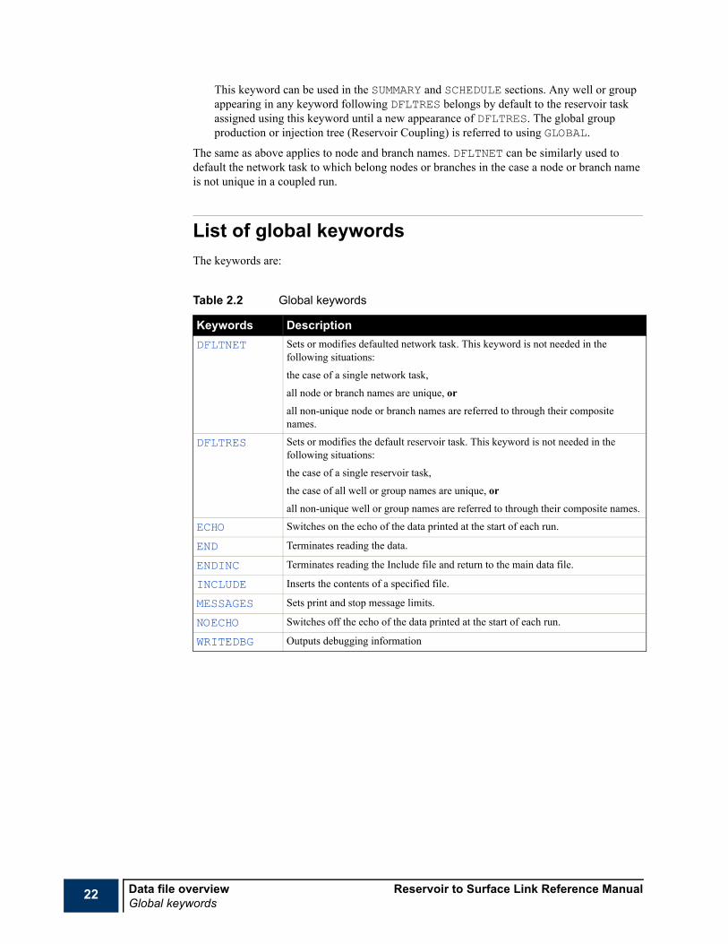
List of global keywordsThe keywords are:
Table 2.2 Global keywords
Keywords DescriptionDFLTNET Sets or modifies defaulted network task. This keyword is not needed in the
following situations:
the case of a single network task,
all node or branch names are unique, or
all non-unique node or branch names are referred to through their composite names.
DFLTRES Sets or modifies the default reservoir task. This keyword is not needed in the following situations:
the case of a single reservoir task,
the case of all well or group names are unique, or
all non-unique well or group names are referred to through their composite names.
ECHO Switches on the echo of the data printed at the start of each run.
END Terminates reading the data.
ENDINC Terminates reading the Include file and return to the main data file.
INCLUDE Inserts the contents of a specified file.
MESSAGES Sets print and stop message limits.
NOECHO Switches off the echo of the data printed at the start of each run.
WRITEDBG Outputs debugging information

Reservoir to Surface Link Reference Manual Data file overviewRUNSPEC section overview
23
RUNSPEC section overviewThis section contains all dimensioning keywords (needed for memory allocation) as well as all other keywords that provide information that cannot be set or modified during the run (with few exceptions). Among these keywords are the task setting and reporting option setting keywords. Keywords can appear in any order in this section, with few exceptions shown below and in appropriate keywords.
RUNSPEC keywordsThe keywords are:
Table 2.3 RUNSPEC keywords
Keywords DescriptionCOMPDIMS Sets maximum dimensions for memory allocation for compositional coupled
simulation.
FEDIMS Field events functionality dimensions.
KVTDIMS Sets dimensions for memory allocation for the K-values tables.
MESLEVEL Messages level from a task.
MFVPDDIM Vapor or liquid mole fraction versus pressure or density tables dimensions.
NETTYPE Specifies network type.
OPTIONSM Activates special options.
RESBNODS Specifies whether individual network boundary nodes correspond to wells or groups in the reservoir simulation.
RPTOPTS Options setting for HTML reports. This keyword is only needed to modify the defaulted options of HTML report generation.
RUNMODE General information about the run. The keyword is only needed if the default options do not apply. If the keyword is entered, it must be the first keyword in the data file.
SUMOPTS Options setting for SUMMARY files.
TASKDIMS Maximum dimensions for memory allocation. The keyword is only needed if the default values are inadequate.
TASKSPEC General information about each of the coupled reservoir or network simulations.
TITLE Specifies the run’s title.
UNITS Unit convention for data input or output.

24 Data file overview Reservoir to Surface Link Reference ManualPROPS section overview
PROPS section overviewThis section is not needed in a black oil coupled run. In a compositional coupled run, the PROPS section contains definitions of one or more fluids.
Any keyword following the FLUID keyword sets data for the current FLUID. This continues until encountering another FLUID keyword or ENDFLUID.
Keywords can appear in an arbitrary order in this section with the following exceptions:
• FLUID should precede any other keyword defining properties for the current FLUID.
• NCOMPS should appear first after keyword FLUID to define the number of components of the current FLUID.
PROPS keywordsThe keywords are:
Table 2.4 PROPS keywords
Keywords DescriptionACF Sets the acentric factors for a set of components.
BIC Sets the binary interaction coefficients for a set of components.
CNAMES Sets the controller’s super set of components.
ENDFLUID Ends a fluid subsection.
EOS Selects equation of state.
FLUID Starts a fluid subsection.
GMFVD Stock tank gas mole fraction versus surface oil density table. Use either this keyword, or YMFVRV or YMFVP in a FLUID section to model black oil delumping.
KVALUES Requests the use of K-values for liquid-vapor phase equilibrium.
KVTABLE K-values versus pressure table.
MW Sets the molecular weights for a set of components.
NCOMPS Sets the number of components in a FLUID subsection. This keyword is mandatory for defining a FLUID and should appear first after FLUID
OMEGAA Equation of state’s Ωa parameters.
OMEGAB Equation of state’s Ωb parameters.
OMFVD Stock tank oil mole fraction versus surface oil density table. Use either this keyword or, XMFVRS or XMFVP in a FLUID section to model black oil delumping
PCRIT Sets the critical pressures for a set of components.
PRCORR Requests modified Peng Robinson equation of state.
SPLITTAB Split parameters table.
SSHIFT Sets the equation of state shift parameters for a set of components.TCRIT Sets the critical temperatures for a set of components.VCRIT Sets the critical volume for a set of components.
Reservoir to Surface Link Reference Manual Data file overviewPROPS section overview
25
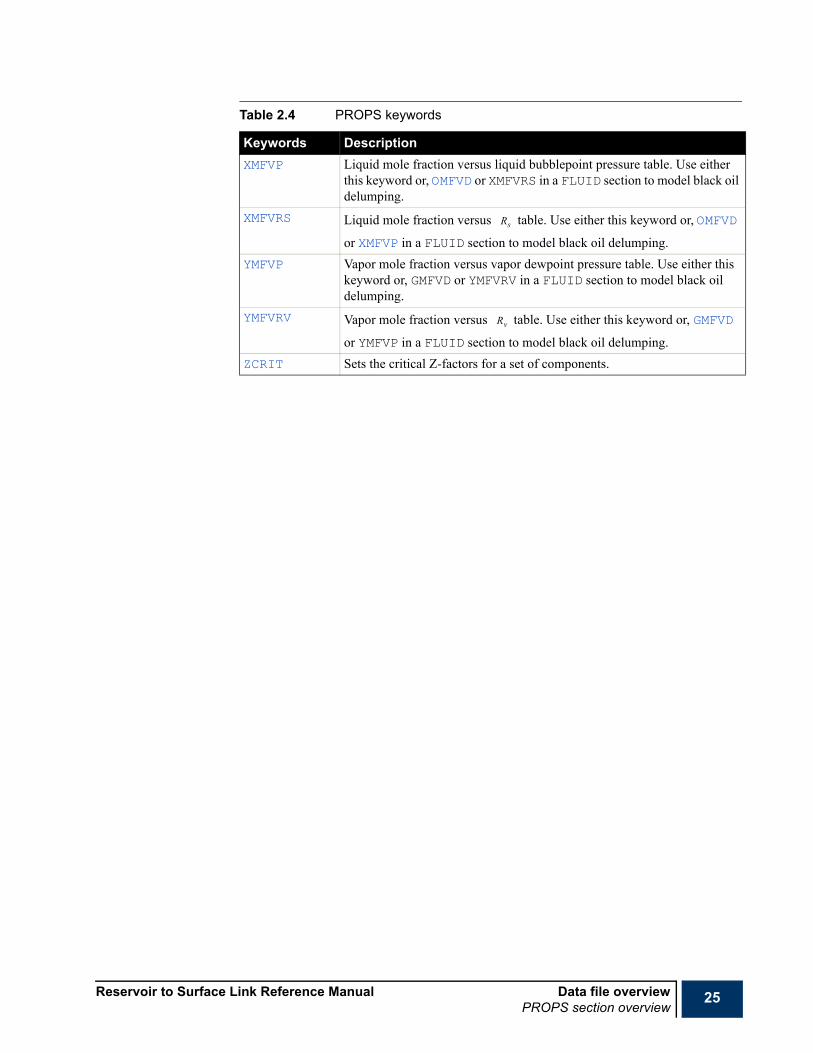
XMFVP Liquid mole fraction versus liquid bubblepoint pressure table. Use either this keyword or, OMFVD or XMFVRS in a FLUID section to model black oil delumping.
XMFVRS Liquid mole fraction versus table. Use either this keyword or, OMFVD
or XMFVP in a FLUID section to model black oil delumping.YMFVP Vapor mole fraction versus vapor dewpoint pressure table. Use either this
keyword or, GMFVD or YMFVRV in a FLUID section to model black oil delumping.
YMFVRV Vapor mole fraction versus table. Use either this keyword or, GMFVD
or YMFVP in a FLUID section to model black oil delumping.ZCRIT Sets the critical Z-factors for a set of components.
Table 2.4 PROPS keywords
Keywords Description
Rs
Rv

26 Data file overview Reservoir to Surface Link Reference ManualSUMMARY section overview
SUMMARY section overviewThe SUMMARY section specifies a number of variables that are to be written to SUMMARY files after each synchronized time step. The graphics post-processor may be used to display the variation of variables in the SUMMARY files with time and with each other. If there is no existing SUMMARY section, R2SL does not create any SUMMARY files.
SUMMARY keywordsThe SUMMARY keywords are:
The keywords that may be specified in the SUMMARY section are shown in the following tables. All are optional, and no significance attaches to the order in which they are specified. All keywords must start in column 1. All characters up to column 8 are significant.
Note “B” can be equally used as first character of branch mnemonics instead of “P”.
Table 2.5 SUMMARY keywords
Keyword DescriptionSUMOPTS Options setting for SUMMARY files.
Table 2.6 Wells and Groups SUMMARY output control
Group Well Completion InformationCOFR Oil Flow Rate (+ve for production, -ve for injection)
CWFR Water Flow Rate (+ve for production, -ve for injection)
CGFR Gas Flow Rate (+ve for production, -ve for injection)
GOPR WOPR COPR Oil Production Rate
GOPT WOPT OIl Production Total
GWPR WWPR CWPR Water Production Rate
GWPT WWPT Water Production Total
GGPR WGPR CGPR Gas Production Rate
GGPT WGPT Gas Production Total
GVPR WVPR Reservoir Volume Production Rate
GVPT WVPT Reservoir Volume Production Total
GOPP Group Oil Production Potential
GGPP Group Gas Production Potential
GWPP Group Water Production Potential
COIR Oil injection rate
GWIR WWIR CWIR Water Injection Rate
GWIT WWIT Water Injection Total
Reservoir to Surface Link Reference Manual Data file overviewSUMMARY section overview
27
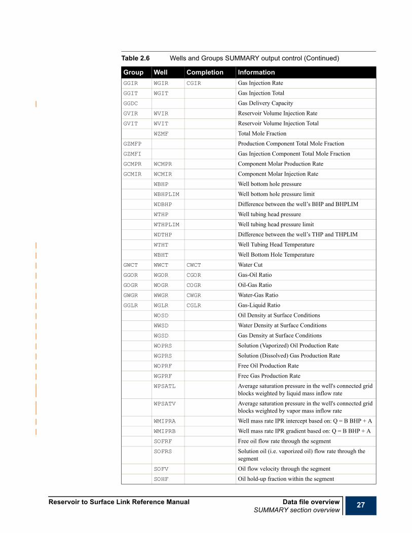
GGIR WGIR CGIR Gas Injection Rate
GGIT WGIT Gas Injection Total
GGDC Gas Delivery Capacity
GVIR WVIR Reservoir Volume Injection Rate
GVIT WVIT Reservoir Volume Injection Total
WZMF Total Mole Fraction
GZMFP Production Component Total Mole Fraction
GZMFI Gas Injection Component Total Mole Fraction
GCMPR WCMPR Component Molar Production Rate
GCMIR WCMIR Component Molar Injection Rate
WBHP Well bottom hole pressure
WBHPLIM Well bottom hole pressure limit
WDBHP Difference between the well’s BHP and BHPLIM
WTHP Well tubing head pressure
WTHPLIM Well tubing head pressure limit
WDTHP Difference between the well’s THP and THPLIM
WTHT Well Tubing Head Temperature
WBHT Well Bottom Hole Temperature
GWCT WWCT CWCT Water Cut
GGOR WGOR CGOR Gas-Oil Ratio
GOGR WOGR COGR Oil-Gas Ratio
GWGR WWGR CWGR Water-Gas Ratio
GGLR WGLR CGLR Gas-Liquid Ratio
WOSD Oil Density at Surface Conditions
WWSD Water Density at Surface Conditions
WGSD Gas Density at Surface Conditions
WOPRS Solution (Vaporized) Oil Production Rate
WGPRS Solution (Dissolved) Gas Production Rate
WOPRF Free Oil Production Rate
WGPRF Free Gas Production Rate
WPSATL Average saturation pressure in the well's connected grid blocks weighted by liquid mass inflow rate
WPSATV Average saturation pressure in the well's connected grid blocks weighted by vapor mass inflow rate
WMIPRA Well mass rate IPR intercept based on: Q = B BHP + A
WMIPRB Well mass rate IPR gradient based on: Q = B BHP + A
SOFRF Free oil flow rate through the segment
SOFRS Solution oil (i.e. vaporized oil) flow rate through the segment
SOFV Oil flow velocity through the segment
SOHF Oil hold-up fraction within the segment
Table 2.6 Wells and Groups SUMMARY output control (Continued)
Group Well Completion Information

28 Data file overview Reservoir to Surface Link Reference ManualSUMMARY section overview
SOSD Surface density of oil in the segment (varies in API tracking runs)
SAPI API of oil in the segment (in API tracking runs)
SWFR Water flow rate through the segment
SWFV Water flow velocity through the segment
SWHF Water hold-up fraction within the segment
SGFR Gas flow rate through the segment
SGFRF Free gas flow rate through the segment
SGFRS Solution gas (i.e. dissolved gas) flow rate through the segment
SGFV Gas flow velocity through the segment
SGHF Gas hold-up fraction within the segment
SPR Pressure at the segment node
SPRD Pressure drop over the segment
SPRDH Hydrostatic pressure drop over the segment
SPRDF Friction pressure drop over the segment
SPRDA Acceleration pressure drop over the segment
SPRDM Current value of the segment's frictional pressure drop multiplier
SALQ ALQ value used in the VFP table look-up to obtain the pressure drop
SOUTL Outlet segment number (next towards wellhead)
SINL Inlet segment number on the same branch (= 0 if at end of branch)
SBRN Branch number
SCMOD Pressure drop calculation model
>0 = VFP table look-up (the VFP table number is reported
-1.0 = homogeneous flow model
-2.0 = drift flux model
-3.0 = labyrinth device model
-4.0 = flow limiting valve
-5.0 = sub-critical valve
-6.0 = pull through pump
SLAYBC Labyrinth device configuration number
SVALVA Sub-critical valve constriction area
SPPOW Applied power of a pull through pump
SGOR Gas-Oil Ratio in the segment
SGLR Gas-Liquid Ratio in the segment
Table 2.6 Wells and Groups SUMMARY output control (Continued)
Group Well Completion Information

Reservoir to Surface Link Reference Manual Data file overviewSUMMARY section overview
29
.
SOGR Oil-Gas Ratio in the segment
SLGR Liquid-Gas Ratio in the segment
SWCUT Water Cut in the segment
Table 2.7 Nodes SUMMARY output control
Nodes InformationNPRES Pressure
NORAT OIl rate along the node’s outlet (inlet) branch in a production (injection) network
NWRAT Water rate along the node’s outlet (inlet) branch in a production (injection) network
NGRAT Gas rate along the node’s outlet (inlet) branch in a production (injection) network
NTEMP Temperature
NZMF Production (gas injection) component mole fraction
NCMPR Production (gas injection) component molar rate
Table 2.8 Branch (PIPE) SUMMARY output control
Branch InformationPDPRES Pressure drop across branch
PEROSVEL Erosional velocity
PEVRATIO Erosional velocity ratio
PLHOLDUP Total Liquid Holdup
PSPHLIQV Sphere-generated liquid volume
PVELMIXI Mixture Velocity at Inlet
PVELMIXO Mixture Velocity at Outlet
PMASFLWO Mass Flowrate at Outlet
PELEVDP Total Elevational Pressure Drop
PFRICDP Total Frictional Pressure Drop
BPPSSG Severe Slugging Group
PSLUGVOL Mean Slug Volume
PSLUGLEN Mean Slug Length
PSLUGFRE Mean Slug Frequency
PCHKD Choke diameter
PCHDT Temperature difference across choke
PCHDP Pressure change across choke
PPPOW Pump power
Table 2.6 Wells and Groups SUMMARY output control (Continued)
Group Well Completion Information

30 Data file overview Reservoir to Surface Link Reference ManualSUMMARY section overview
Examples
PPEFF Pump efficiency
PPPDC Pump pressure discharge
PPPDI Pump pressure differential
PPPRA Pump pressure ratio
PPSPE Pump speed
PPSUP Pump suction pressure
PPTDI Temperature difference across pump
PCPOW Compressor power
PCEFF Compressor efficiency
PCPDC Compressor pressure discharge
PCPDI Compressor pressure differential
PCPRA Compressor pressure ratio
PCSPE Compressor speed
PCSUP Compressor suction pressure
PCTDI Temperature difference across compressor
PGLRA Gas lift rate
PGLSD Gas lift density
PGLTE Gas lift temperature
Table 2.9 Task SUMMARY output control
Parameter InformationIELAPTIM Elapsed time
ICPUTIME CPU time
SUMOPTSMULTIPLE FORMAT /GOPRSR-A1 ‘PL-A*@RES1’ ‘PL-B*@R*’ /WOPT‘PR*’ ‘IWA2’ /
Table 2.8 Branch (PIPE) SUMMARY output control (Continued)
Branch Information
Reservoir to Surface Link Reference Manual Data file overviewSCHEDULE section overview
31
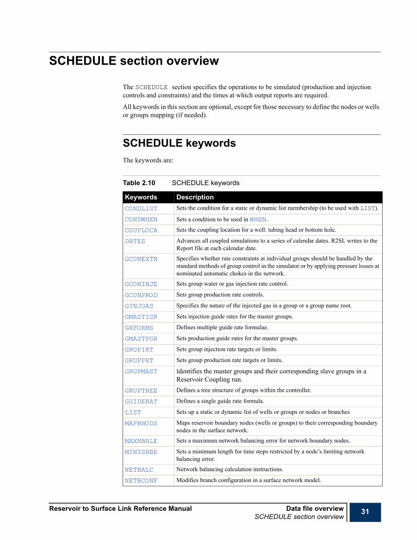
SCHEDULE section overview
The SCHEDULE section specifies the operations to be simulated (production and injection controls and constraints) and the times at which output reports are required.
All keywords in this section are optional, except for those necessary to define the nodes or wells or groups mapping (if needed).
SCHEDULE keywordsThe keywords are:
Table 2.10 SCHEDULE keywords
Keywords DescriptionCONDLIST Sets the condition for a static or dynamic list membership (to be used with LIST).
CONDWHEN Sets a condition to be used in WHEN.
COUPLOCA Sets the coupling location for a well: tubing head or bottom hole.
DATES Advances all coupled simulations to a series of calendar dates. R2SL writes to the Report file at each calendar date.
GCONEXTN Specifies whether rate constraints at individual groups should be handled by the standard methods of group control in the simulator or by applying pressure losses at nominated automatic chokes in the network.
GCONINJE Sets group water or gas injection rate control.
GCONPROD Sets group production rate controls.
GINJGAS Specifies the nature of the injected gas in a group or a group name root.
GMASTIGR Sets injection guide rates for the master groups.
GRFORMS Defines multiple guide rate formulae.
GMASTPGR Sets production guide rates for the master groups.
GRUPIRT Sets group injection rate targets or limits.
GRUPPRT Sets group production rate targets or limits.
GRUPMAST Identifies the master groups and their corresponding slave groups in a Reservoir Coupling run.
GRUPTREE Defines a tree structure of groups within the controller.
GUIDERAT Defines a single guide rate formula.
LIST Sets up a static or dynamic list of wells or groups or nodes or branches
MAPBNODS Maps reservoir boundary nodes (wells or groups) to their corresponding boundary nodes in the surface network.
MAXNBALE Sets a maximum network balancing error for network boundary nodes.
MINTSNBE Sets a minimum length for time steps restricted by a node’s limiting network balancing error.
NETBALC Network balancing calculation instructions.
NETBCONF Modifies branch configuration in a surface network model.
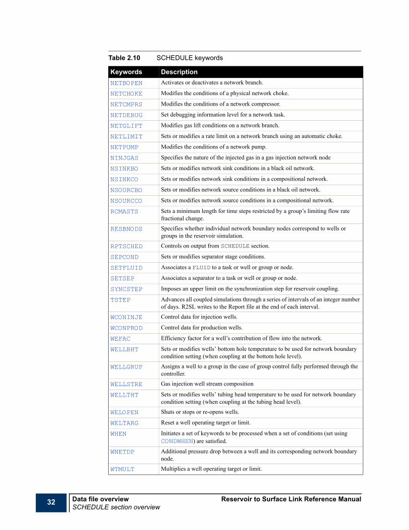
32 Data file overview Reservoir to Surface Link Reference ManualSCHEDULE section overview
NETBOPEN Activates or deactivates a network branch.
NETCHOKE Modifies the conditions of a physical network choke.
NETCMPRS Modifies the conditions of a network compressor.
NETDEBUG Set debugging information level for a network task.
NETGLIFT Modifies gas lift conditions on a network branch.
NETLIMIT Sets or modifies a rate limit on a network branch using an automatic choke.
NETPUMP Modifies the conditions of a network pump.
NINJGAS Specifies the nature of the injected gas in a gas injection network node
NSINKBO Sets or modifies network sink conditions in a black oil network.
NSINKCO Sets or modifies network sink conditions in a compositional network.
NSOURCBO Sets or modifies network source conditions in a black oil network.
NSOURCCO Sets or modifies network source conditions in a compositional network.
RCMASTS Sets a minimum length for time steps restricted by a group’s limiting flow rate fractional change.
RESBNODS Specifies whether individual network boundary nodes correspond to wells or groups in the reservoir simulation.
RPTSCHED Controls on output from SCHEDULE section.
SEPCOND Sets or modifies separator stage conditions.
SETFLUID Associates a FLUID to a task or well or group or node.
SETSEP Associates a separator to a task or well or group or node.
SYNCSTEP Imposes an upper limit on the synchronization step for reservoir coupling.
TSTEP Advances all coupled simulations through a series of intervals of an integer number of days. R2SL writes to the Report file at the end of each interval.
WCONINJE Control data for injection wells.
WCONPROD Control data for production wells.
WEFAC Efficiency factor for a well’s contribution of flow into the network.
WELLBHT Sets or modifies wells’ bottom hole temperature to be used for network boundary condition setting (when coupling at the bottom hole level).
WELLGRUP Assigns a well to a group in the case of group control fully performed through the controller.
WELLSTRE Gas injection well stream composition
WELLTHT Sets or modifies wells’ tubing head temperature to be used for network boundary condition setting (when coupling at the tubing head level).
WELOPEN Shuts or stops or re-opens wells.
WELTARG Reset a well operating target or limit.
WHEN Initiates a set of keywords to be processed when a set of conditions (set using CONDWHEN) are satisfied.
WNETDP Additional pressure drop between a well and its corresponding network boundary node.
WTMULT Multiplies a well operating target or limit.
Table 2.10 SCHEDULE keywords
Keywords Description

Reservoir to Surface Link Reference Manual IntroductionWhat is Reservoir to Surface Link?
33
Chapter 3Introduction
What is Reservoir to Surface Link?Reservoir to Surface Link or R2SL is a controller for the ECLIPSE simulators (ECLIPSE 100 and ECLIPSE 300). It can:
1 Couple one or more ECLIPSE reservoir simulations to one or more external surface network models, keeping the networks balanced with the production and injection rates as the reservoir conditions evolve over time. Currently, the available network models are:
a PIPESIM Net.
This is Schlumberger’s network simulator. It has a wide selection of built-in correlations for pipe and device pressure losses, and allows looped networks as well as gathering or distribution trees.
b Petroleum Experts GAP network model.
2 Couple two or more ECLIPSE reservoir simulations that are subject to common global constraints.
The ECLIPSE models can have different PVT descriptions (black oil and compositional) (See "Compositional aspects" in the "Reservoir to Surface Link Technical Description").
The Lookup Table module is a fast proxy model of a reservoir. For further information see"Lookup Table Module" on page 241.
The Black Oil Tank Model provides a simple analytical representation of an oil reservoir. For further information see "The Black Oil Tank Model" on page 269.

34 Introduction Reservoir to Surface Link Reference ManualWhat is Reservoir to Surface Link?
Reservoir to Surface Link Reference Manual Using R2SLIntroduction
35
Chapter 4Using R2SL
IntroductionThis chapter contains some examples illustrating typical R2SL workflows.
These examples encompass the main functionality of R2SL as discussed in "Reservoir to Simulation Link" in the "Reservoir to Surface Link Technical Description".
Examples• "Coupling a single reservoir simulation to a production network" on page 36,
• "Coupling multiple reservoir simulations through common production or injection group control" on page 39,
• "Coupling multiple reservoir simulations to surface facility networks:" on page 43.
• "Coupling multiple reservoir simulations to surface facility networks" on page 47

36 Using R2SL Reservoir to Surface Link Reference ManualCoupling a single reservoir simulation to a production network
Coupling a single reservoir simulation to a production network
The following example illustrates a typical controller data file for coupling a black oil reservoir model to a black oil production surface network model. The maximum number of wells, groups and network nodes are defined using TASKDIMS. The use of this keyword is encouraged; otherwise large amounts of memory are allocated.
One issue when coupling reservoir models to surface facility networks is the boundary nodes mapping. That is, which reservoir boundary node (a well or a well-group) corresponds to which network boundary node. Two boundary nodes mapping options are available and can be selected using RUNMODE:
1 AUTOMAP:
For each network boundary node, the controller searches the reservoir simulations for a well group having the same name. If none is found, it then searches for a well with the same name. Well groups and wells should have unique names in this case.
2 MANUMAP:
The reservoir boundary nodes (or part of them) have different names to the corresponding network boundary nodes. MAPBNODS is used to set correspondence between reservoir boundary nodes and the network boundary nodes in this case.
The reservoir boundary nodes might be wells, well groups, or a mixture of wells and well groups. This should be selected in item 8 of a TASKSPEC record. In the case the MANUMAP option is selected, RESBNODS is used to select the reservoir boundary nodes.
A fixed pressure drop between the well groups boundary nodes and their subordinate wells is applied using WNETDP.
NETLIMIT is used to set an upper limit on overall oil rate production rate. It is used later once again to modify the rate limits using automatic chokes. Upper limits on water, gas, and liquid rates can also be set using this keyword. Setting rate constraints might also be done using internal group control as discussed in "Rate constraints" in the "Reservoir to Surface Link Technical Description".
RPTSCHED is used to specify the details to be generated in the HTML files at each controller reporting time. Details about GROUPS, WELLS and NODES are wanted. MESSAGES of warnings and above are reported.
Vectors to be included in the SUMMARY files are set in the SUMMARY section. Defaulted options are used: UNFORMAT, SEPARATE and MULTIPLE. Oil and water vectors are wanted for groups MAN1 and MAN2. Oil, water and gas rate vectors are wanted for all network nodes.
Twelve reporting times are specified using TSTEP. Another report is wanted at 31 MAR 2005 using DATES.
Note The network balancing scheme, frequency and tolerance are defaulted. NETBALC can be used to modify these instructions.
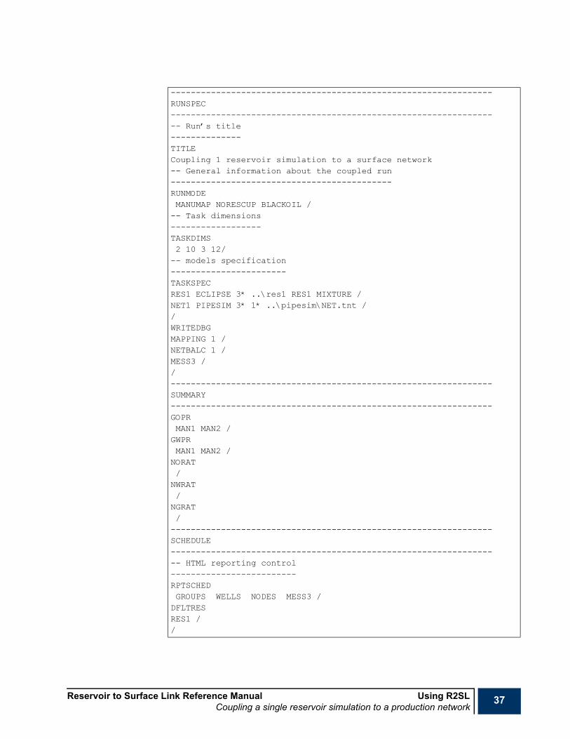
Reservoir to Surface Link Reference Manual Using R2SLCoupling a single reservoir simulation to a production network
37
----------------------------------------------------------------RUNSPEC------------------------------------------------------------------ Run’s title--------------TITLECoupling 1 reservoir simulation to a surface network-- General information about the coupled run--------------------------------------------RUNMODEMANUMAP NORESCUP BLACKOIL /-- Task dimensions------------------TASKDIMS2 10 3 12/-- models specification-----------------------TASKSPECRES1 ECLIPSE 3* ..\res1 RES1 MIXTURE /NET1 PIPESIM 3* 1* ..\pipesim\NET.tnt //WRITEDBGMAPPING 1 /NETBALC 1 /MESS3 //----------------------------------------------------------------SUMMARY----------------------------------------------------------------GOPRMAN1 MAN2 /GWPRMAN1 MAN2 /NORAT/NWRAT/NGRAT/----------------------------------------------------------------SCHEDULE------------------------------------------------------------------ HTML reporting control-------------------------RPTSCHEDGROUPS WELLS NODES MESS3 /DFLTRESRES1 //

38 Using R2SL Reservoir to Surface Link Reference ManualCoupling a single reservoir simulation to a production network
-- Reservoir to network nodes selection-------------------------------------RESBNODSPROD1 WELL /PROD2 WELL /PROD3 WELL /PROD4 WELL /PROD5 WELL /PROD5 WELL /MAN1 GROUP /MAN2 GROUP /
-- Reservoir/network boundary nodes mapping-------------------------------------------MAPBNODSR1W5 PROD5 /R1W6 PROD6 /R2W3 PROD3 /R2W4 PROD4 /MAN1 MAN1 /MAN2 MAN2 //WNETDPPA1@RES1 10 //-- Rate Limit at the terminal node----------------------------------------NETLIMITGATHER_CHK ORATLIM 40000 //NETBALC2* 25 /-- Time stepping----------------TSTEP31 28 31 30 31 30 31 31 30 31 30 31 /-- Modify rate limit--------------------------NETLIMITGATHER_CHK ORATLIM 20000 //-- Time specified as DATES----------------DATES1 FEB 2004 /1 APR 2004 /1 JUN 2004 /1 JAN 2005 /1 JUN 2005 //END

Reservoir to Surface Link Reference Manual Using R2SLCoupling multiple reservoir simulations through common production or injection group control
39
Coupling multiple reservoir simulations through common production or injection group control
Black oil modeIn this example, three black oil ECLIPSE simulation models are coupled through common production or injection group control. The coupled run does not contain a surface network model.
A global group tree is defined using GRUPTREE (which is mandatory in this case) in which three master groups are defined. The master groups’ corresponding slaves are the FIELD groups from the three reservoir models. Master or slave correspondence is set using GRUPMAST. Using GRUPMAST is mandatory in this situation since the master groups correspond to slaves with different names.
DFLTRES is used to default the task to the GLOBAL tree so that, any group name appearing latter in the keyword belong, by default to this group tree (unless its task is explicitly set using the “@” character or the group name is unique in the coupled run).
RES1 re-injects half of its produced gas, and all three reservoirs inject water to make up a voidage replacement fraction of 0.8. This is set using GCONINJE. No need for injection guide rates in this case since the injection group control happens at the master level.
An oil production target of 30,000 Stb/day is set at the EXPORT level using GCONPROD. The overall production is limited by water and gas production limits of 10,000 and 100,000, respectively.
GCONINJE and GCONPROD can be used to set or modify targets and limits on the groups belonging to the global tree as well as those belonging to any of the coupled reservoir models.
GRUPIRT and GRUPPRT can also be used to set simple injection and production targets or limits, respectively.
The master groups’ guide rates are set using a formulae (see GUIDERAT) in which oil phase guide rates are set equal to the oil phase potentials, to be recalculated after 100 day intervals. The guide rate formulae defined in GUIDERAT is associated to the master groups using GMASTPGR.
Group production and injection guide rates can be defined directly in GMASTPGR and GMASTIGR, respectively. This is the case when the group guide rate is equal to the group’s production rate (of a given phase) or to the group’s production (injection) potential. More sophisticated guide rate formulae can be defined using GUIDERAT (and more generally GRFORMS) to define group production guide rates.
To limit the amount of information sent from the reservoirs to the controller, only warning messages and above are sent from the reservoir models to the controller; this is set using MESLEVEL. Note that this does not affect the messages reporting in each model.
As discussed in "Multiple reservoirs synchronization" in the "Reservoir to Surface Link Technical Description", the controller selects a synchronized time step accounting for different events. In this example, a maximum length of 15 days for the synchronization steps is set using keyword.

40 Using R2SL Reservoir to Surface Link Reference ManualCoupling multiple reservoir simulations through common production or injection group control
The fraction by which a master group’s reservoir volume flow rate can change over a single timestep is limited to 0.1 (10%) as set in GRUPMAST. RCMASTS is used in order to set to 2 days the minimum length for timesteps restricted by a master group’s limiting flow rate fractional change. it is also advisable to set a minimum timestep length that this restriction can impose, as the fractional flow changes can be large when the flows are small and wells are being opened or closed in the slave reservoirs.
.
RUNSPEC------------------------------------------------------------------ Run’s title--------------TITLECoupling 3 reservoir simulations through common constraints-- General information about the coupled run--------------------------------------------RUNMODEAUTOMAP RESCUP BLACKOIL /-- Task dimensions------------------TASKDIMS3 150 80 90/-- models specification-----------------------TASKSPECRES1 ECLIPSE 1* 1* 1* '../res1' 'RES1' WELLS /RES2 ECLIPSE 1* 1* 1* '../res2' 'RES2' WELLS /RES3 ECLIPSE 1* 1* 1* '../res3' 'RES3' WELLS //-- Messages level from the reservoir models-------------------------------------------MESLEVELRES1 3/RES2 3 /RES3 3 //-- Debugging information------------------------WRITEDBGMESSAGES 1 /MAPPING 1 /NETBAL 1 /FEVENTS 1/

Reservoir to Surface Link Reference Manual Using R2SLCoupling multiple reservoir simulations through common production or injection group control
41
--------------------------------------------------------------------------------------------------------------------------------SUMMARY----------------------------------------------------------------GOPR‘*@GLOBAL’/GWPR‘*@GLOBAL’/GGPR‘*@GLOBAL’/----------------------------------------------------------------SCHEDULE------------------------------------------------------------------ HTML reporting control-------------------------RPTSCHEDGROUPS WELLS SYNCINFO MESS3 /-- Default task to GLOBAL tree------------------------------DFLTRESGLOBAL /--- Global group tree---------------------GRUPTREEMAN-A EXPORT /MAN-B EXPORT /MAN-C EXPORT //--- Master/slave correspondence-------------------------------GRUPMASTMAN-A RES1 FIELD 0.1 /MAN-B RES2 FIELD 0.1 /MAN-C RES3 FIELD 0.1 //--- Lower limit on synchronized step chopping---------------------------------------------RCMASTS2 /--- Injection group control---------------------------GCONINJEMAN-A GAS REIN 2* 0.5 /MAN-A WATER VREP 2* 1* 0.8 /MAN-B WATER VREP 2* 1* 0.8 /MAN-C WATER VREP 2* 1* 0.8 //-- Guide Rate Formulae

42 Using R2SL Reservoir to Surface Link Reference ManualCoupling multiple reservoir simulations through common production or injection group control
----------------------GUIDERAT100 OIL 1.0 1.0 /-- Production Guide Rates-------------------------GMASTPGRMAN-A 1* FORM1 /MAN-B 1* FORM1 /MAN-C 1* FORM1 //-- Production Control---------------------GCONPRODEXPORT ORAT 30000 10000 1.E+05 /MAN-A NONE 1* 1* 15000 1* 1* NO//-- Upper limit on synchronization time steps--------------------------------------------SYNCSTEP15 /...DATES1 FEB 1990 /END
Reservoir to Surface Link Reference Manual Using R2SLCoupling multiple reservoir simulations to surface facility networks:
43
Coupling multiple reservoir simulations to surface facility networks:
Black oil modeIn this example, three black oil ECLIPSE simulation models are connected to a common production network. The reservoirs boundary nodes are all wells as specified in TASKSPEC. The AUTOMAP option is selected in RUNMODE since all reservoir boundary nodes are unique names and they have the same names as the network boundary nodes they map to. No need for the use of MAPBNODS and RESBNODS in this case.
Production limits are applied on two branches of the network. The branches on which automatic chokes are applied are created for the purpose; they are short horizontal branches with zero roughness as discussed in NETLIMIT).
Global trees for multiple reservoir coupling through common injection or production control can co-exist with common production networks. In this example, injection targets or limits are applied through common injection group control. A distribution tree is build for the purpose using GRUPTREE. The tree defines three master groups each linked to the FIELD group in the reservoir tasks, as defined using GRUPMAST. The same injection group control is applied here as in the example above using GCONINJE.
The network balancing tolerance is set to 2% using NETBALC. In the context of multiple reservoir coupling this keyword can also be used to modify the defaulted values of the number of network balancing iterations in which a well can be revived after being closed because it cannot operate against its current THP. In the context of a single reservoir coupling to surface facility networks, this keyword has a wider use. For instance, it can be used to switch from iteratively lagged coupling to explicit coupling or loose coupling, or to set the network balancing frequency.
You do not have to worry about network balancing accuracy when infrequent reports (as is the case in this example using DATES). SYNCSTEP are used to set a maximum length for the synchronization steps.
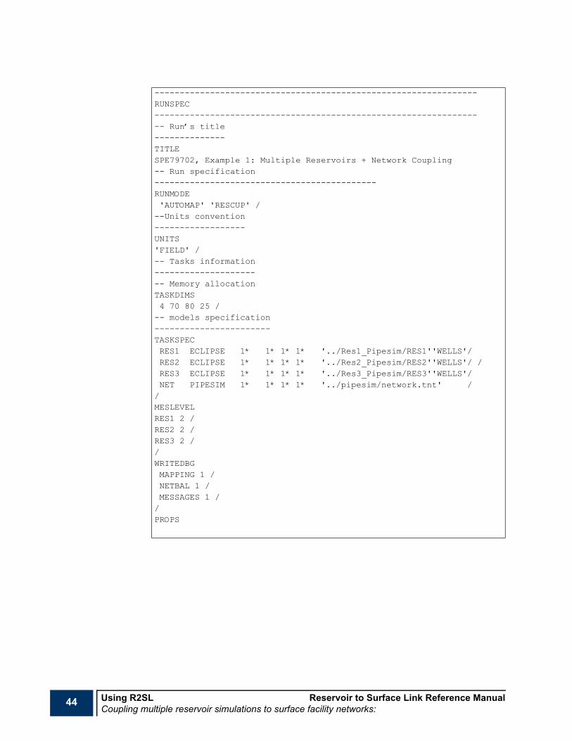
44 Using R2SL Reservoir to Surface Link Reference ManualCoupling multiple reservoir simulations to surface facility networks:
----------------------------------------------------------------RUNSPEC------------------------------------------------------------------ Run’s title--------------TITLESPE79702, Example 1: Multiple Reservoirs + Network Coupling-- Run specification--------------------------------------------RUNMODE'AUTOMAP' 'RESCUP' /--Units convention------------------UNITS'FIELD' /-- Tasks information---------------------- Memory allocationTASKDIMS4 70 80 25 /-- models specification-----------------------TASKSPECRES1 ECLIPSE 1* 1* 1* 1* '../Res1_Pipesim/RES1''WELLS'/RES2 ECLIPSE 1* 1* 1* 1* '../Res2_Pipesim/RES2''WELLS'/ /RES3 ECLIPSE 1* 1* 1* 1* '../Res3_Pipesim/RES3''WELLS'/NET PIPESIM 1* 1* 1* 1* '../pipesim/network.tnt' //MESLEVELRES1 2 /RES2 2 /RES3 2 //WRITEDBGMAPPING 1 /NETBAL 1 /MESSAGES 1 //PROPS

Reservoir to Surface Link Reference Manual Using R2SLCoupling multiple reservoir simulations to surface facility networks:
45
SUMMARYGOPR/GOWR/GOGR/NORAT/NWRAT/NGRAT/----------------------------------------------------------------SCHEDULE------------------------------------------------------------------ HTML reporting control-------------------------RPTSCHEDGROUPS WELLS NODES SYNCINFO MESS3 /
-- Default task to GLOBAL tree------------------------------DFLTRESGLOBAL /-- Global group tree--------------------GRUPTREEMAN-A EXPORT /MAN-B EXPORT /MAN-C EXPORT //--- Master/slave correspondence-------------------------------GRUPMASTMAN-A RES1 FIELD /MAN-B RES2 FIELD /MAN-C RES3 FIELD //-- Network rate limit setting------------------------NETLIMITGATHER_CHK ORATLIM 30000 /MAN-A_CHK GRATLIM 15000 //--- Injection group control---------------------------GCONINJEMAN-A GAS REIN 2* 0.5 /MAN-A WATER VREP 2* 1* 0.8 /MAN-B WATER VREP 2* 1* 0.8 /MAN-C WATER VREP 2* 1* 0.8 //
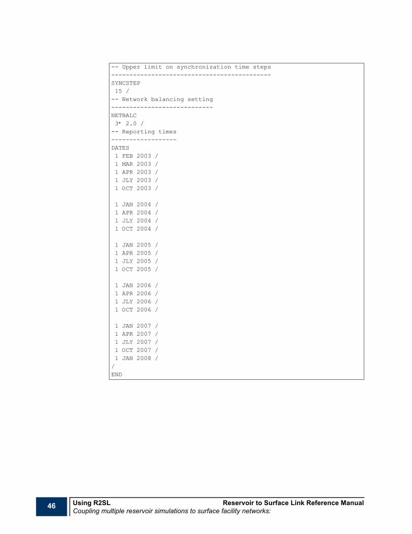
46 Using R2SL Reservoir to Surface Link Reference ManualCoupling multiple reservoir simulations to surface facility networks:
-- Upper limit on synchronization time steps--------------------------------------------SYNCSTEP15 /-- Network balancing setting----------------------------NETBALC3* 2.0 /-- Reporting times------------------DATES1 FEB 2003 /1 MAR 2003 /1 APR 2003 /1 JLY 2003 /1 OCT 2003 /
1 JAN 2004 /1 APR 2004 /1 JLY 2004 /1 OCT 2004 /
1 JAN 2005 /1 APR 2005 /1 JLY 2005 /1 OCT 2005 /
1 JAN 2006 /1 APR 2006 /1 JLY 2006 /1 OCT 2006 /
1 JAN 2007 /1 APR 2007 /1 JLY 2007 /1 OCT 2007 /1 JAN 2008 //END
Reservoir to Surface Link Reference Manual Using R2SLCoupling multiple reservoir simulations to surface facility networks
47
Coupling multiple reservoir simulations to surface facility networks
Compositional aspectsWhen coupling reservoir models to surface facility networks in a compositional mode the following situations might be encountered.
Black oil surface network modelA single compositional reservoir model coupled to a black oil surface network model. In this situation, the run should be defined as BLACKOIL (item 3 of RUNMODE). No compositional information is needed for the coupled run in this context.
Compositional surface network models
Same set of componentsA single compositional reservoir model coupled to a compositional surface network model with the same set of components
The following keywords are needed:
RUNSPEC section COMPDIMS to define the number of components in the controller’s super-set of components (which is basically the same set of components as the two models).
PROPS section FLUID Starts a fluid subsection.PROPS section NCOMPS Needed to set the number of components in MW.PROPS section MW Needed for mass or molar rate conversion.
Different set of componentsA single compositional reservoir model coupled to a compositional surface network model with a different set of components
The following keywords are needed:RUNSPEC section COMPDIMS Defines the number of components in the controller’s super-set of components
(which is basically the same set of components as the two models).PROPS section FLUID Starts a fluid subsection.PROPS section NCOMPS Sets the number of components in MW.
PROPS section MW Needed for mass or molar rate conversion.PROPS section CNAMES To define the super set of components as well as to be used when reading SPLITTAB.PROPS section SPLITTAB For lumping or delumping the task’s set of components into the super-set of
components.
A FLUID defining the super-set of components is needed as well as a FLUID for each task for which the set of components is different from the super set of components.

48 Using R2SL Reservoir to Surface Link Reference ManualCoupling multiple reservoir simulations to surface facility networks
Black oil reservoir modelA single black oil reservoir model coupled to a compositional surface network model
The following keywords are needed:RUNSPEC section COMPDIMS Defines the number of components in the controller’s super-set of components
(which is basically the same set of components as the two models).RUNSPEC section MFVPDDIM Sets the dimensions of the black oil delumping tables.
PROPS section FLUID Starts a fluid subsection.PROPS section NCOMPS Sets the number of components in applicable keywords.PROPS section MW Needed for black oil delumping.PROPS section CNAMES Defines the super set of components mainly for reporting purposes as well as to be
used when reading SPLITTAB (when the latter keyword is used).
PROPS section XMFVP or OMFVD Defines liquid mole fraction versus liquid bubblepoint pressure (stock tank oil density) table.
PROPS section XMFVRS Defines liquid mole fraction versus liquid bubblepoint pressure, solution gas oil ratio or stock tank oil density.
PROPS section YMFVP or GMFVD Defines vapor mole fraction versus vapor dew point pressure (stock tank oil density) table.
PROPS section YMFVRV Defines vapor mole fraction versus vapor dew point, vaporized oil to gas ratio or stock tank oil density.
PROPS section SPLITTAB For compositional lumping or delumping the task’s set of components into the super-set of components only if the resulting set of components after black oil delumping is different from the super set of components.
Liquid-vapor phase equilibriumSome facilities require flash calculation. These include:
• compositional gas re-injection using GINJGAS (or NINJGAS) when item 2 of this keyword is set to GV (NV), or,
• The FGROUP option is used in RPTSCHED to output the global groups production reports obtained by flashing the produced hydrocarbon mixture under given separator conditions, or,
• The option FLASH is used in WRITEDBG.
In the above cases, necessary information for flash calculation is needed in the appropriate FLUID. For instance, the typical information needed in the case of the two-parameters Peng Robinson equation of state is:
TCRIT Sets the critical temperatures for a set of components.
PCRIT Sets the critical pressures for a set of components.
ACF Sets the acentric factors for a set of components.
BIC Sets the binary interaction coefficients for a set of components.
ExampleIn this example, three reservoirs with different fluid descriptions (one black oil and one 6-component model, two compositional) are coupled through global group production or injection control. The reservoir models are:

Reservoir to Surface Link Reference Manual Using R2SLCoupling multiple reservoir simulations to surface facility networks
49
1 RES1 is a black oil model,
2 RES2 is a 6-components or pseudo-components model, and
3 RES3 is an 11 component or pseudo-components model.
The option COMPOS is activated in RUNMODE. The 11 components in RES3 adopted as being the controller’s super-set of components (FLUID 3, defined first in the PROPS section). Compositional dimensioning is set using COMPDIMS and MFVPDDIM.
At the beginning of each synchronization time step, the controller delumps the 6-components compositional wellstream from RES2 into the super-set of components using a split parameters table (see "Compositional aspects" in the "Reservoir to Surface Link Technical Description").
Similarly, the controller delumps the black oil wellstream into the super-set of components using tables of vapor or liquid composition versus saturation pressure (see "Compositional aspects" in the "Reservoir to Surface Link Technical Description").
A global oil production target of 30,000 Stb/day is set using GCONPROD. Reservoirs A and B inject water to make up voidage replacement fraction of 0.8 and 1.0 respectively. This is set using GCONINJE. This keyword is also used to inject the gas produced at the terminal group GATHER to make up a voidage replacement of 1.0. Gas injection in RES3 is, however, limited by the amount of gas produced at GATHER and by a gas compression capacity of 150,000 Mscf/day.
The composition of the gas injected in RES3 is set using GINJGAS. The gas composition is that of the vapor resulting from a two-stage separator at GATHER.
Having a separator requires flashing which might take place using the following two options:
1 K-values table look-up using the KVALUES option that requires K-values tables (using KVTABLE), or
2 EOS flashing (adopted in the following example).

50 Using R2SL Reservoir to Surface Link Reference ManualCoupling multiple reservoir simulations to surface facility networks
----------------------------------------------------------------RUNSPEC------------------------------------------------------------------ Run’s title--------------TITLESPE79702, Example 2, Compositional Aspects of R2SL-- Run specification--------------------------------------------RUNMODE'AUTOMAP' 'RESCUP' 'COMPOS' /-- Debugging information------------------------WRITEDBGMAPPING 1 /NETBAL 1 /MESSAGES 1 /BODELUMP 1 /FLDELUMP 1 /FLASH 1 //-- Memory allocation--------------------TASKDIMS3 50 50 1 /-- Tasks definition-------------------TASKSPEC'RES1' 'ECLIPSE' 1* 1* 1* '../RES1/RES1' /'RES2' 'E300' 1* 1* 1* '../RES2/RES2' /'RES3' 'E300' 1* 1* 1* '../RES3/RES3' //-- Compositional dimensions---------------------------COMPDIMS-- Actual number of delumped components = 11-- Maximum number of lumped components = 11-- Maximum number of split parameter tables = 4-- Maximum number of FLUIDs = 4-- Maximum number of Wellstreams = 5-- Maximum number of separators = 2-- Maximum number of stages per separator = 3---------------------------------------------11 11 4 4 5 2 3 /--Mole fraction/pressure tables dimensions(for blackoil delumping of RES1)-------------------------------------------FVPDDIM1 10 50 /

Reservoir to Surface Link Reference Manual Using R2SLCoupling multiple reservoir simulations to surface facility networks
51
----------------------------------------------------------------PROPS----------------------------------------------------------------NOECHOFLUID3 /NCOMPS11 /EOSPR /CNAMESN2 CO2 C1 C2 C3 HC46 HC7 HC13 HC18 HC26 HC43 /TCRIT227.16 547.56 343.07 549.774 665.64 820.8 1035.0 1198.8 1323.0 1452.6 1645.2 /PCRIT492.3 1071.3 667.78 708.34 618.69 504.25 441.1 327.8 237.8 174.0 147.4 /MW28.02 44.01 16.04 30.07 44.09 67.98 110.14 173.11 248.85 361.77 600.98 /ACF0.040 0.225 0.0080 0.09860 0.15240 0.2325 0.4210 0.7174 0.9849 1.2737 1.6704 /BIC0.00.02 0.120.06 0.15 0.00.08 0.15 2*0.00.08 0.15 3*0.00.08 0.15 4*0.00.08 0.15 5*0.00.08 0.15 6*0.00.08 0.15 7*0.00.08 0.15 8*0.0/ENDFLUIDFLUID1 /NCOMPS10 /CNAMESN2 CO2 C1 HC23 HC46 HC7 HC13 HC18 HC26 HC43 /MW2.801300000E+01 4.401000000E+01 1.604300000E+01 3.588000000E+016.798000000E+01 1.101400000E+02 1.731100000E+02 2.488500000E+023.617700000E+02 6.009800000E+02 /

52 Using R2SL Reservoir to Surface Link Reference ManualCoupling multiple reservoir simulations to surface facility networks
-- Split parameter table------------------------SPLITTAB-- number of lumped components = 10-- number of delumped components = 11N2 1.0 N2CO2 1.0 CO2C1 1.0 C1HC23 0.585 C2HC23 0.415 C3HC46 1.0 HC46HC7 1.0 HC7HC13 1.0 HC13HC18 1.0 HC18HC26 1.0 HC26HC43 1.0 HC43/--Vapor mole fraction versus pressure table-----------------------------------------INCLUDEYMFVP.INC/--Liquid mole fraction versus pressure table-----------------------------------------INCLUDEXMFVP.INC/-- Specify the end of a fluid section-------------------------------------ENDFLUIDFLUID2 /NCOMPS6 /CNAMESN2 CO2 C1 HC23 HC46 C7+ /
-- Split parameter table-------------------------SPLITTAB-- number of lumped components = 6-- number of delumped components = 11N2 1.0 N2CO2 1.0 CO2C1 1.0 C1HC23 0.585 C2HC23 0.415 C3HC46 1.0 HC46C7+ 0.41 HC7C7+ 0.25 HC13C7+ 0.16 HC18C7+ 0.11 HC26C7+ 0.07 HC43/ENDFLUID
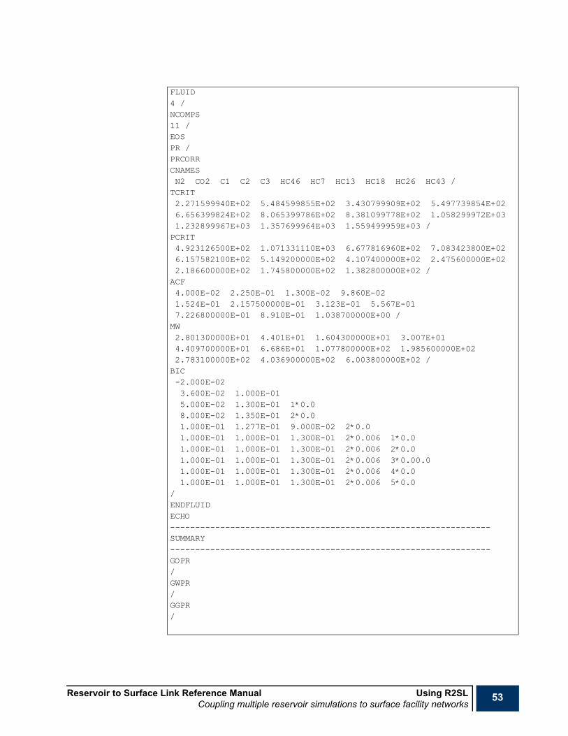
Reservoir to Surface Link Reference Manual Using R2SLCoupling multiple reservoir simulations to surface facility networks
53
FLUID4 /NCOMPS11 /EOSPR /PRCORRCNAMESN2 CO2 C1 C2 C3 HC46 HC7 HC13 HC18 HC26 HC43 /TCRIT2.271599940E+02 5.484599855E+02 3.430799909E+02 5.497739854E+026.656399824E+02 8.065399786E+02 8.381099778E+02 1.058299972E+031.232899967E+03 1.357699964E+03 1.559499959E+03 /PCRIT4.923126500E+02 1.071331110E+03 6.677816960E+02 7.083423800E+026.157582100E+02 5.149200000E+02 4.107400000E+02 2.475600000E+022.186600000E+02 1.745800000E+02 1.382800000E+02 /ACF4.000E-02 2.250E-01 1.300E-02 9.860E-021.524E-01 2.157500000E-01 3.123E-01 5.567E-017.226800000E-01 8.910E-01 1.038700000E+00 /MW2.801300000E+01 4.401E+01 1.604300000E+01 3.007E+014.409700000E+01 6.686E+01 1.077800000E+02 1.985600000E+022.783100000E+02 4.036900000E+02 6.003800000E+02 /BIC-2.000E-023.600E-02 1.000E-015.000E-02 1.300E-01 1*0.08.000E-02 1.350E-01 2*0.01.000E-01 1.277E-01 9.000E-02 2*0.01.000E-01 1.000E-01 1.300E-01 2*0.006 1*0.01.000E-01 1.000E-01 1.300E-01 2*0.006 2*0.01.000E-01 1.000E-01 1.300E-01 2*0.006 3*0.00.01.000E-01 1.000E-01 1.300E-01 2*0.006 4*0.01.000E-01 1.000E-01 1.300E-01 2*0.006 5*0.0
/ENDFLUIDECHO----------------------------------------------------------------SUMMARY----------------------------------------------------------------GOPR/GWPR/GGPR/

54 Using R2SL Reservoir to Surface Link Reference ManualCoupling multiple reservoir simulations to surface facility networks
GVPR/GWIR/GGIR/GVIR/GZMFP/GZMFI/----------------------------------------------------------------SCHEDULE----------------------------------------------------------------RPTSCHEDGROUPS WELLS SYNCINFO MESS3 FGROUP /DFLTRESGLOBAL /GRUPTREEMAN-A EXPORT /MAN-B EXPORT /MAN-C EXPORT //GRUPMASTMAN-A RES1 FIELD /MAN-B RES2 FIELD /MAN-C RES3 FIELD //-- Separators-------------SEPCONDSEP1 1* 1 80 65 /SEP1 1* 2 60 14.7 //SYNCSTEP10/-- Set fluid for each task/group--------------------------------SETFLUIDTASK RES1 1 /TASK RES2 2 /TASK RES3 3 /TASK GLOBAL 3 /GROUP EXPORT@GLOBAL 4 /GROUP MAN-A@GLOBAL 3 /GROUP MAN-B@GLOBAL 3 /GROUP MAN-C@GLOBAL 4 //

Reservoir to Surface Link Reference Manual Using R2SLCoupling multiple reservoir simulations to surface facility networks
55
-- Set separator for each task------------------------------SETSEPTASK RES1 SEP1 /TASK RES2 SEP1 /TASK RES3 SEP1 /TASK GLOBAL SEP1 /GROUP MAN-A@GLOBAL SEP1 /GROUP MAN-B@GLOBAL SEP1 /GROUP MAN-C@GLOBAL SEP1 //-- Define production guide rates as potential----------------------------------------------GMASTPGRMAN-A 1* POTN /MAN-B 1* POTN /MAN-C 1* POTN //-- Field production control---------------------------GCONPRODEXPORT ORAT 30000 //-- Gas injection control--------------------------GCONINJEGroup Phase CTRL RATE RESV REIN VREP REIN G VREP GMAN-C GAS VREP 150000 1* 1.0 1.0 3* EXPORT MAN-C //-- Define the injection gas composition------------------------------------------GINJGASMAN-C GV EXPORT //-- Water injection control----------------------------GCONINJEMAN-A WATER VREP 3* 0.8 4* MAN-A /MAN-B WATER VREP 3* 1.0 4* MAN-B //
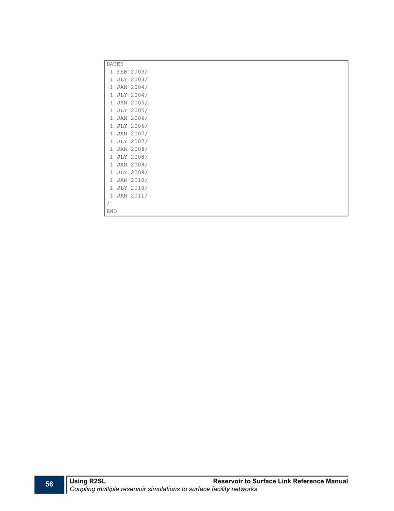
56 Using R2SL Reservoir to Surface Link Reference ManualCoupling multiple reservoir simulations to surface facility networks
DATES1 FEB 2003/1 JLY 2003/1 JAN 2004/1 JLY 2004/1 JAN 2005/1 JLY 2005/1 JAN 2006/1 JLY 2006/1 JAN 2007/1 JLY 2007/1 JAN 2008/1 JLY 2008/1 JAN 2009/1 JLY 2009/1 JAN 2010/1 JLY 2010/1 JAN 2011//END
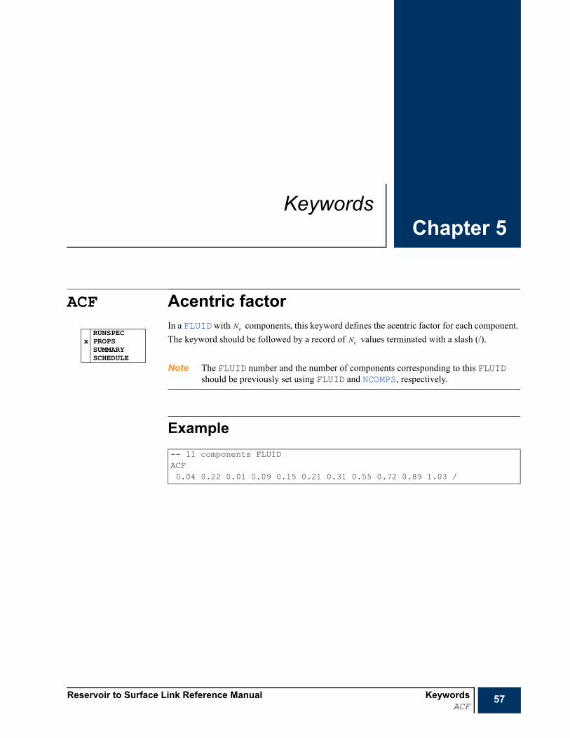
Reservoir to Surface Link Reference Manual KeywordsACF
57
Chapter 5Keywords
ACF Acentric factor In a FLUID with components, this keyword defines the acentric factor for each component. The keyword should be followed by a record of values terminated with a slash (/).
Note The FLUID number and the number of components corresponding to this FLUID should be previously set using FLUID and NCOMPS, respectively.
Example
RUNSPECx PROPS
SUMMARYSCHEDULE
-- 11 components FLUIDACF0.04 0.22 0.01 0.09 0.15 0.21 0.31 0.55 0.72 0.89 1.03 /
Nc
Nc
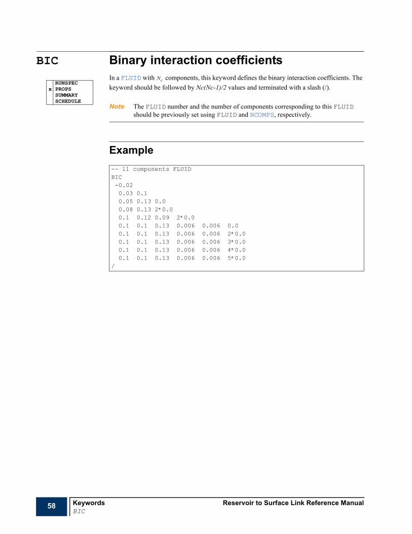
58 Keywords Reservoir to Surface Link Reference ManualBIC
BIC Binary interaction coefficients In a FLUID with components, this keyword defines the binary interaction coefficients. The keyword should be followed by Nc(Nc-1)/2 values and terminated with a slash (/).
Note The FLUID number and the number of components corresponding to this FLUID should be previously set using FLUID and NCOMPS, respectively.
Example
RUNSPECx PROPS
SUMMARYSCHEDULE
-- 11 components FLUIDBIC-0.020.03 0.10.05 0.13 0.00.08 0.13 2*0.00.1 0.12 0.09 2*0.00.1 0.1 0.13 0.006 0.006 0.00.1 0.1 0.13 0.006 0.006 2*0.00.1 0.1 0.13 0.006 0.006 3*0.00.1 0.1 0.13 0.006 0.006 4*0.00.1 0.1 0.13 0.006 0.006 5*0.0
/
Nc

Reservoir to Surface Link Reference Manual KeywordsCNAMES
59
CNAMES Component namesIn a FLUID with components, this keyword defines the component name for each component. The keyword should be followed by a record of names terminated with a slash (/).
Note The number of components should be previously set using NCOMPS.
Example
RUNSPECx PROPS
SUMMARYSCHEDULE
-- 11 components FLUIDCNAMESN2 CO2 C1 C2 C3 HC46 HC7 HC13 HC18 HC26 HC43 /
Nc
Nc
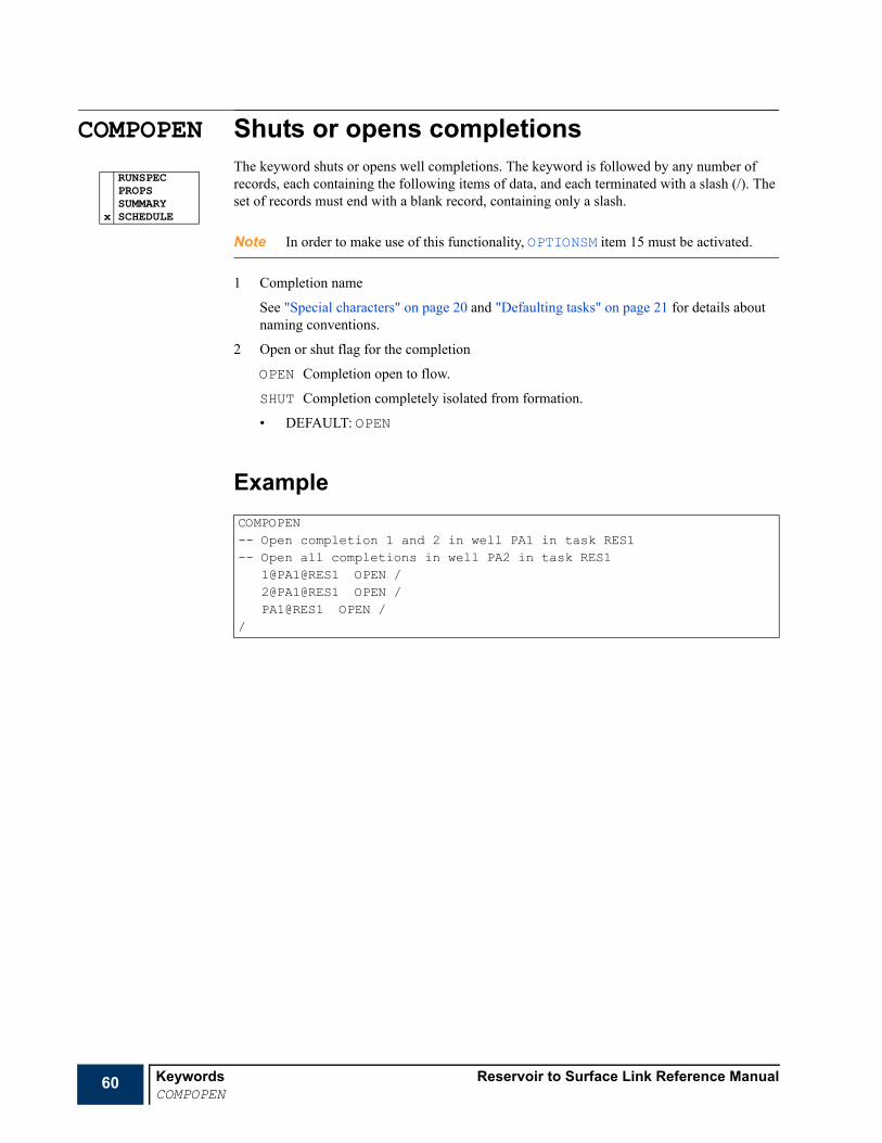
60 Keywords Reservoir to Surface Link Reference ManualCOMPOPEN
COMPOPEN Shuts or opens completionsThe keyword shuts or opens well completions. The keyword is followed by any number of records, each containing the following items of data, and each terminated with a slash (/). The set of records must end with a blank record, containing only a slash.
Note In order to make use of this functionality, OPTIONSM item 15 must be activated.
1 Completion name
See "Special characters" on page 20 and "Defaulting tasks" on page 21 for details about naming conventions.
2 Open or shut flag for the completion
OPEN Completion open to flow.
SHUT Completion completely isolated from formation.
• DEFAULT: OPEN
Example
RUNSPECPROPSSUMMARY
x SCHEDULE
COMPOPEN-- Open completion 1 and 2 in well PA1 in task RES1-- Open all completions in well PA2 in task RES1
1@PA1@RES1 OPEN /2@PA1@RES1 OPEN /PA1@RES1 OPEN /
/
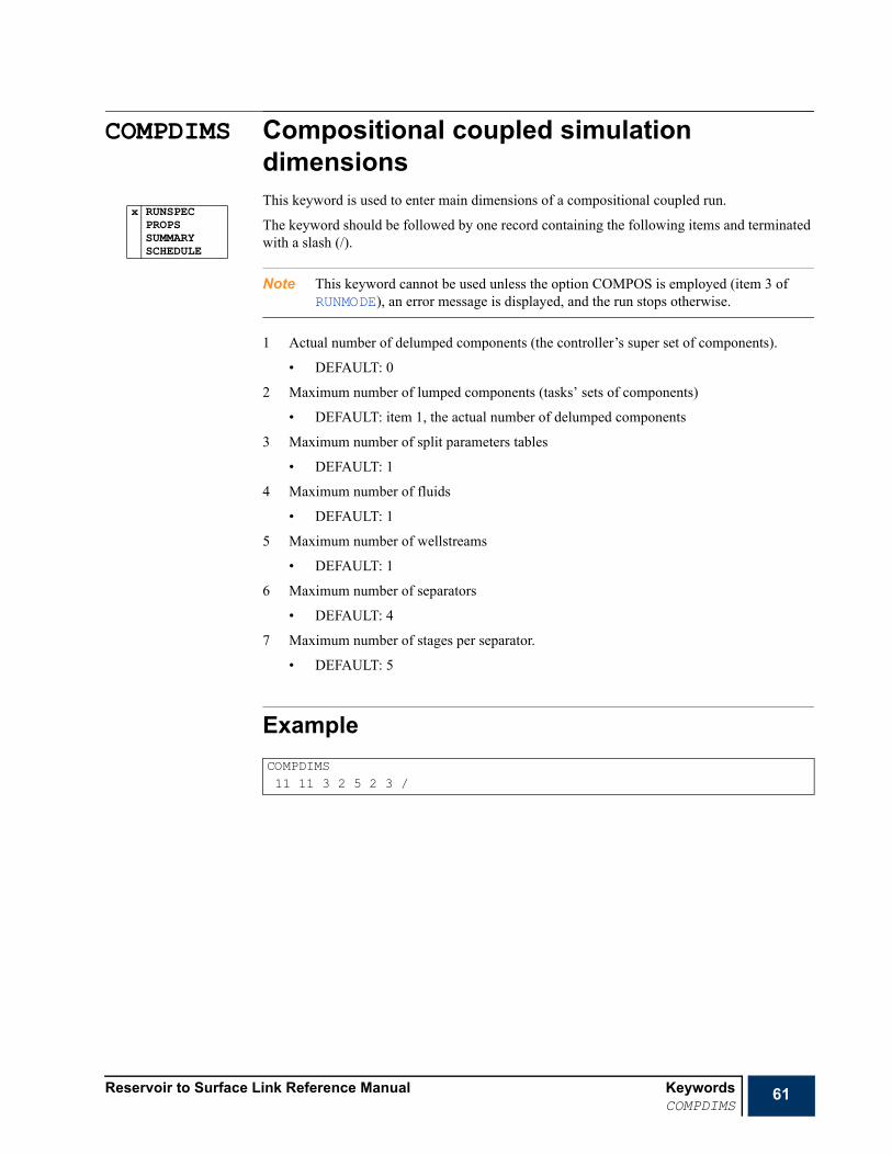
Reservoir to Surface Link Reference Manual KeywordsCOMPDIMS
61
COMPDIMS Compositional coupled simulation dimensionsThis keyword is used to enter main dimensions of a compositional coupled run.
The keyword should be followed by one record containing the following items and terminated with a slash (/).
Note This keyword cannot be used unless the option COMPOS is employed (item 3 of RUNMODE), an error message is displayed, and the run stops otherwise.
1 Actual number of delumped components (the controller’s super set of components).
• DEFAULT: 0
2 Maximum number of lumped components (tasks’ sets of components)
• DEFAULT: item 1, the actual number of delumped components
3 Maximum number of split parameters tables
• DEFAULT: 1
4 Maximum number of fluids
• DEFAULT: 1
5 Maximum number of wellstreams
• DEFAULT: 1
6 Maximum number of separators
• DEFAULT: 4
7 Maximum number of stages per separator.
• DEFAULT: 5
Example
x RUNSPECPROPSSUMMARYSCHEDULE
COMPDIMS11 11 3 2 5 2 3 /
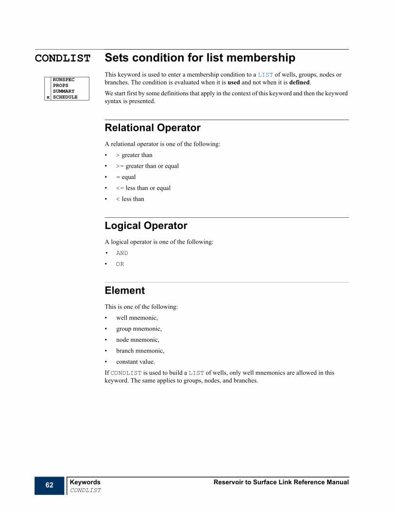
62 Keywords Reservoir to Surface Link Reference ManualCONDLIST
CONDLIST Sets condition for list membershipThis keyword is used to enter a membership condition to a LIST of wells, groups, nodes or branches. The condition is evaluated when it is used and not when it is defined.
We start first by some definitions that apply in the context of this keyword and then the keyword syntax is presented.
Relational OperatorA relational operator is one of the following:
• > greater than
• >= greater than or equal
• = equal
• <= less than or equal
• < less than
Logical OperatorA logical operator is one of the following:
• AND
• OR
ElementThis is one of the following:
• well mnemonic,
• group mnemonic,
• node mnemonic,
• branch mnemonic,
• constant value.
If CONDLIST is used to build a LIST of wells, only well mnemonics are allowed in this keyword. The same applies to groups, nodes, and branches.
RUNSPECPROPSSUMMARY
x SCHEDULE

Reservoir to Surface Link Reference Manual KeywordsCONDLIST
63
The mnemonics that can be used in this keyword (as well as in CONDWHEN) are summarized in the following tables.
Table 5.1 Well, group and branch mnemonics that can be used in a condition for list membership.
Well Group Completion InformationCOFR Oil Flow Rate (+ve Production / -ve Injection)
CWFR Water Flow Rate
CGFR Gas Flow Rate
WOPR GOPR COPR Oil Production Rate
WWPR GWPR CWPR Water Production Rate
WGPR GGPR CGPR Gas Production Rate
WLPR GLPR Liquid Production Rate
WVPR GVPR Reservoir Volume Production Rate
WOPT GOPT Oil Production Total
WWPT GWPT Water Production Total
WGPT GGPT Gas Production Total
WLPT GLPT Liquid Production Total
WVPT GVPT Reservoir Volume Production Total
WOPP GOPP Oil Potential Production Rate
WWPP GWPP Water Potential Production Rate
WGPP GGPP Gas Potential Production Rate
WLPP GLPP Liquid Potential Production Rate
WVPP GVPP Reservoir Volume Potential Production Rate
COIR Oil Injection Rate
WWIR GWIR CWIR Water Injection Rate
WGIR GGIR CGIR Gas Injection Rate
WVIR GVIR Reservoir Volume Injection Rate
WWIT GWIT Water Injection Total
WGIT GGIT Gas Injection Total
WVIT GVIT Reservoir Volume Injection Total
WWIP GWIP Water Potential Injection Rate
WGIP GGIP Gas Potential Injection Rate
WVIP GVIP Reservoir Volume Potential Injection Rate
WOWR GOWR COWR Oil-Water Ratio
WOGR GOGR COGR Oil-Gas Ratio
WOLR GOLR COLR Oil-Liquid Ratio
WWOR GWOR CWOR Water-Oil Ratio
WWGR GWGR CWGR Water-Gas Ratio
WWLR, WWCT GWLR, GWCT CWLR, CWCT Water-Liquid Ratio
WGOR GGOR CGOR Gas-Oil Ratio
WGWR GGWR GGWR Gas-Water Ratio
WGLR GGLR CGLR Gas-Liquid Ratio
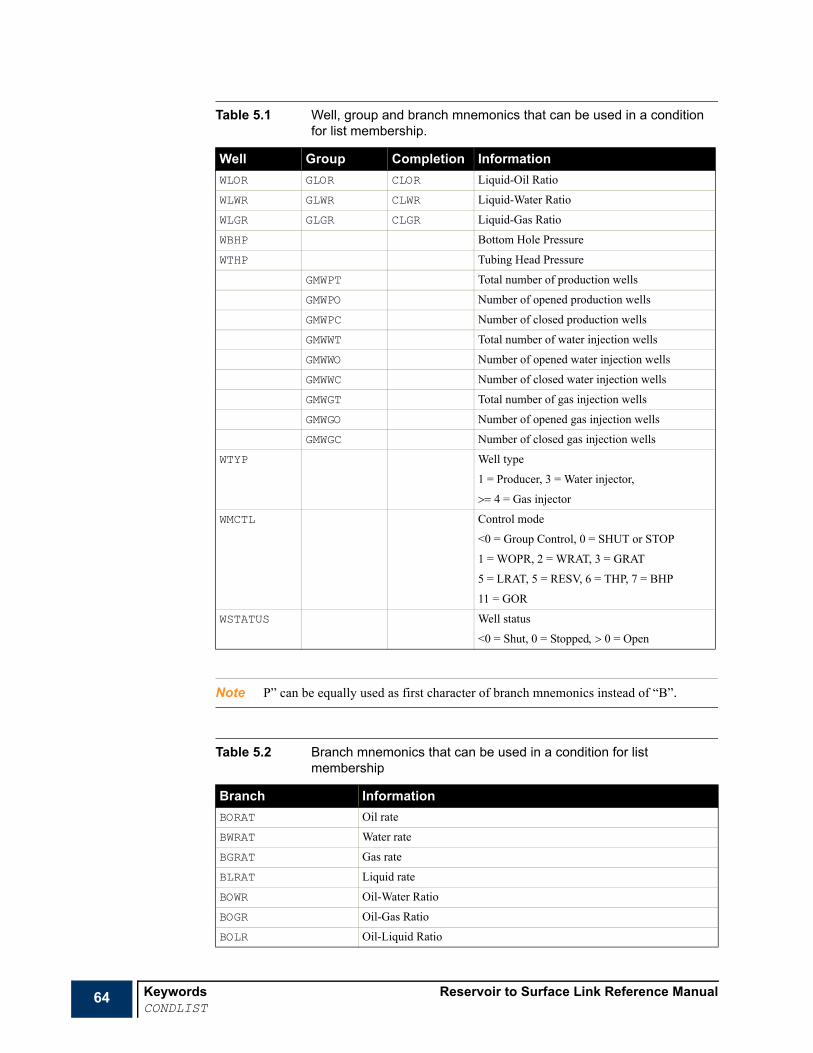
64 Keywords Reservoir to Surface Link Reference ManualCONDLIST
Note P” can be equally used as first character of branch mnemonics instead of “B”.
WLOR GLOR CLOR Liquid-Oil Ratio
WLWR GLWR CLWR Liquid-Water Ratio
WLGR GLGR CLGR Liquid-Gas Ratio
WBHP Bottom Hole Pressure
WTHP Tubing Head Pressure
GMWPT Total number of production wells
GMWPO Number of opened production wells
GMWPC Number of closed production wells
GMWWT Total number of water injection wells
GMWWO Number of opened water injection wells
GMWWC Number of closed water injection wells
GMWGT Total number of gas injection wells
GMWGO Number of opened gas injection wells
GMWGC Number of closed gas injection wells
WTYP Well type
1 = Producer, 3 = Water injector,
>= 4 = Gas injector
WMCTL Control mode
<0 = Group Control, 0 = SHUT or STOP
1 = WOPR, 2 = WRAT, 3 = GRAT
5 = LRAT, 5 = RESV, 6 = THP, 7 = BHP
11 = GOR
WSTATUS Well status
<0 = Shut, 0 = Stopped, > 0 = Open
Table 5.2 Branch mnemonics that can be used in a condition for list membership
Branch InformationBORAT Oil rate
BWRAT Water rate
BGRAT Gas rate
BLRAT Liquid rate
BOWR Oil-Water Ratio
BOGR Oil-Gas Ratio
BOLR Oil-Liquid Ratio
Table 5.1 Well, group and branch mnemonics that can be used in a condition for list membership.
Well Group Completion Information

Reservoir to Surface Link Reference Manual KeywordsCONDLIST
65
BWOR Water-Oil Ratio
BWGR Water-Gas Ratio
BWLR Water-Liquid Ratio
BGOR Gas-Oil Ratio
BGWR Gas-Water Ratio
BGLR Gas-Liquid Ratio
BLOR Liquid-Oil Ratio
BLWR Liquid-Water Ratio
BLGR Liquid-Gas Ratio
BDPRES Pressure drop across branch
BEROSVEL Erosional velocity
BEVRATIO Erosional velocity ratio
BLHOLDUP Total Liquid Holdup
BSPHLIQV Sphere-generated liquid volume
BVELMIXI Mixture Velocity at Inlet
BVELMIXO Mixture Velocity at Outlet
BMASFLWO Mass Flowrate at Outlet
BELEVDP Total Elevational Pressure Drop
BFRICDP Total Frictional Pressure Drop
BPPSG Severe Slugging Group
BSLUGVOL Mean Slug Volume
BSLUGLEN Mean Slug Length
BSLUGFRE Mean Slug Frequency
BCHKD Choke diameter
BCHDT Temperature difference across choke
BCHDP Pressure change across choke
BPPOW Pump power
BPEFF Pump efficiency
BPPDC Pump pressure discharge
BPPDI Pump pressure differential
BPPRA Pump pressure ratio
BPSPE Pump speed
BPSUP Pump suction pressure
BPTDI Temperature difference across pump
BCPOW Compressor power
BCEFF Compressor efficiency
BCPDC Compressor pressure discharge
BCPDI Compressor pressure differential
BCPRA Compressor pressure ratio
Table 5.2 Branch mnemonics that can be used in a condition for list membership (Continued)
Branch Information
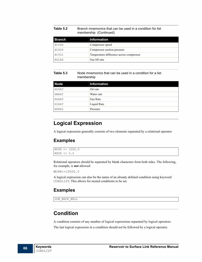
66 Keywords Reservoir to Surface Link Reference ManualCONDLIST
Logical ExpressionA logical expression generally consists of two elements separated by a relational operator
Examples
Relational operators should be separated by blank characters from both sides. The following, for example, is not allowed:
WOPR<=10000.0
A logical expression can also be the name of an already defined condition using keyword CONDLIST. This allows for nested conditions to be set.
Examples
ConditionA condition consists of any number of logical expressions separated by logical operators.
The last logical expression in a condition should not be followed by a logical operator.
BCSPE Compressor speed
BCSUP Compressor suction pressure
BCTDI Temperature difference across compressor
BGLRA Gas lift rate
Table 5.3 Node mnemonics that can be used in a condition for a list membership
Node InformationNORAT Oil rate
NWRAT Water rate
NGRAT Gas Rate
NLRAT Liquid Rate
NPRES Pressure
WOPR >= 1000.0WGOR <= 5.0
LOW_WGOR_WELL
Table 5.2 Branch mnemonics that can be used in a condition for list membership (Continued)
Branch Information

Reservoir to Surface Link Reference Manual KeywordsCONDLIST
67
Examples
Note A condition can be split into several lines. Blank line as well as comment lines (starting with --) can also be entered in a condition.
Example
Keyword SyntaxThe keyword is followed by two records of data, each terminated with a slash (/). The set of records must end with a blank record, containing only a slash.
Record 11 Condition name: up to 32 characters.
Record 2The record starts with a blank line containing just the bracket character “[“and should be terminated with a blank line containing just the bracket character “]“. Between these two lines, a condition should be entered.
Examples
Example 1This example defines the membership condition to a list of groups with a GOR higher than 5.0
WOPR >= 1000.0 AND WGOR <= 5.0WOPR >= 1000.0 OR LOW_WGOR_WELL
-- High oil rate wellsWOPR >= 1000.0 AND-- Low GOR wellsWGOR <= 5.0
CONDLISTHigh_GOR_Groups /
[GGOR >= 5.0
]/

68 Keywords Reservoir to Surface Link Reference ManualCONDLIST
Example 2This example defines the membership condition to a list of wells with the GOR > 50 only if the GOR of the group to which the well belongs is higher than 5.0
Example 3This example illustrates the use of nested conditions.
CONDLISTHigh_GOR_Wells /
[WGOR >= 5.0 ANDGGOR >= 5.0
]/
CONDLISTHigh_GOR_Wells /
[WGOR >= 5.0
]/CONDLIST
High_GOR__High_WCT_Wells /[
WWCT >= 0.8 AND High_GOR_Wells]/

Reservoir to Surface Link Reference Manual KeywordsCONDWHEN
69
CONDWHEN Condition for field events handlingThis keyword is used to enter a condition to be used in a WHEN keyword. This defines the condition that, if satisfied, results in a set of SCHEDULE keyword being processed. A condition is evaluated when it is used and not when it is defined.
We start first by some definitions that apply in the context of this keyword and then the keyword syntax is presented
Relational OperatorA relational operator is one of the following:
• > greater than
• >= greater than or equal
• = equal
• <= less than or equal
• < less than
Logical OperatorA logical operator is one of the following:
• AND
• OR
ElementAn element generally consists of three parts: Mnemonic@Object@Task.
1 Mnemonic is one of the following
• well mnemonic,
• group mnemonic,
• node mnemonic,
• branch mnemonic,
• time mnemonic.
RUNSPECPROPSSUMMARY
x SCHEDULE

70 Keywords Reservoir to Surface Link Reference ManualCONDWHEN
Mnemonics that can be used are summarized in Table 5.4 (those which are common with CONDWHEN) as wells as in the following time mnemonics;
2 Object is one of the following:
• a well name, well name root, or a list of wells, or
• a group name, group name root, or a list of groups, or
• a node name, node name root, or a list of nodes, or
• a branch name, branch name root, or a list of branches, or
3 Task is:
a a reservoir task name, or a reservoir task name root, or
b a network task name, or a network task name root.
Note In the case of a time mnemonic, Object and Task should be left blank.
Note An element might be constant value, in this case, Mnemonic is a real number and Object and Task should be left blank.
FunctionsThe following prefixes (functions) can be used in a Mnemonic in the case the Object is a root name or a LIST of objects
ALL_ the values represented by Mnemonic of all the objects defined by Object
ANY_ the values represented by Mnemonic of any of the objects defined by Object
AVG_ average (defined as a total rate / total rate) of the values represented by Mnemonic of all the objects defined by Object
MAX_ maximum among of the values represented by Mnemonic of all the objects defined by Object
MIN_ minimum among of the values represented by Mnemonic of all the objects defined by Object
SUM_ sum of the values represented by Mnemonic of all the objects defined by Object
In the case of:
• the Object is a root name or a LIST of objects, and,
• prefix functions are absent from the Mnemonic
Table 5.4 Time mnemonics that can be used in a condition within the keyword CONDWHEN.
Time InformationTIME Simulation time
TDAY Simulation day
TMON Simulation month
TYEAR Simulation year

Reservoir to Surface Link Reference Manual KeywordsCONDWHEN
71
the function ANY_ is applied by default.
ExamplesWGOR@WELL3@RES2 where WELL3 is a well name and RES2 is a reservoir task name.
GOPR@PLAT-A@RES3 where PLAT-A is a group name and RES3 is a reservoir task name.
AVG_WGOR@PR*@RES2 this represents the average GOR of all producers starting with name root PR belonging to task RES2.
MAX_WGOR@PR*@RES2 this represents the GOR of the well with the highest GOR among all producers starting with name root PR belonging to task RES2.
SUM_GOPR@*@RES3 this represents the sum of oil production rate of all producers belonging to task RES3.
AVG_WGOR@PR*@* this represents the average GOR of all producers starting with name root PR belonging to all reservoir tasks.
AVG_WGOR@*@* this represents the average GOR of all producers belonging to all reservoir tasks.
TMON.
AVG_WWCT@%LIST1 where LIST1 is a list of wells (see LIST). This represents the average WCT of all producers belonging to list LIST1.
3000.0 a constant value.
Note The use of single quotes around an element is optional.
Examples
Logical ExpressionA logical expression generally consists of two elements separated by a relational operator
Examples
Relational operators should be separated by blank characters from both sides. The following, for example, is not allowed:
A logical expression can also be the name of an already defined condition using keyword CONDLIST. This allows for nested conditions to be set.
WOPR@WELL3@RES2
ORAT@WELL3@RES2 < ORAT@PROD1@RES3
ORAT@WELL3@RES2<ORAT@PROD1@RES3

72 Keywords Reservoir to Surface Link Reference ManualCONDWHEN
Examples
ConditionA condition consists of any number of logical expressions separated by logical operators.
The last logical expression in a condition should not be followed by a logical operator.
Example
A condition can be split into several lines.
Note Blank line as well as comment lines (starting with --) can also be entered in a condition.
Example
Keyword syntaxThe keyword is followed by the following records or sections. The set of records should be terminated with a blank record containing just a slash.
Record 11 Condition name: up to 32 characters.
This record should be terminated by a slash.
Record 2The record starts with a blank line containing just the bracket character “[“and should be terminated with a blank line containing just the bracket character “]“. Between these two lines, a condition should be entered.
LOW_GOR_WELLS
'WOPR@PA*@RES1' >= 10000 OR 'WGPR@PA*@RES1' >= 20000
-- enough potential production rate of PA* wells'SUM_WOPP@PA*@RES1' >= 10000 OR-- high oil production of the same wells'SUM_WOPR@PA*@RES1' >= 8000

Reservoir to Surface Link Reference Manual KeywordsCONDWHEN
73
Example-- condition keyword for field events---------------------------------------------CONDWHEN-- condition name-----------------HIGH_GRAT /-- logical expressions----------------------[
'GGPR@PLAT-A@RES1' >= 10000 OR'MAX_WGOR@PA*@RES1' >= 7.0
]/

74 Keywords Reservoir to Surface Link Reference ManualCOUPLOCA
COUPLOCA Sets coupling location for a wellThe keyword is used to set or modify the coupling location for a well when coupling a reservoir model to surface facility networks. Item 8 of TASKSPEC can be used to set the coupling location for all the relevant wells (those coupling to a surface network node) of an ECLIPSE task. COUPLOCA sets or modifies the coupling location of a sub-set of an ECLIPSE task’s set of wells.
The keyword is followed by any number of records, each containing the following items of data, and each terminated with a slash (/). The set of records must end with a blank record, containing only a slash.
1 Well name
See "Special characters" on page 20 and "Defaulting tasks" on page 21 for details about naming conventions.
2 Coupling location
TH Coupling at the tubing head level
BH Coupling at the bottom hole level
• DEFAULT: TH
Note R2SL displays a warning message when the coupling location of a well is the tubing head and the well tubing is not defined in the network model. It also displays a warning message when the coupling location of a well is the bottom hole and the well tubing is defined in the network model.
3 Constraint to be set at the end of the network balancing process
ORATLIM Oil rate target or upper limit
WRATLIM Water rate target or upper limit
GRATLIM Gas rate target or upper limit
LRATLIM Liquid rate target or upper limit
VRATLIM Reservoir fluid volume target or upper limit
THPLIM Tubing head pressure target or limit
BHPLIM Bottom hole pressure target or limit
• DEFAULT: THPLIM in the case of coupling at the tubing head level or VRATLIM in the case of coupling at the bottom hole level
Example
RUNSPECPROPSSUMMARY
x SCHEDULE
COUPLOCA‘PR*@RES1’ BH //

Reservoir to Surface Link Reference Manual KeywordsDATES
75
DATES Advances all coupled simulations to specified report date(s)The keyword should be followed by a list of dates at which reports are required from R2SL. Each date must be on a separate line terminated by a slash (/). A null record terminates the data (that is a slash character on a line by itself).
A date consists of three items of data
1 The day of the month
(An integer between 1 and 31)
2 The name of the month abbreviated to three characters
(JAN, FEB, MAR, APR, MAY, JUN, JLY, AUG, SEP, OCT, NOV or DEC).
JUL is an acceptable alternative to JLY.
3 The year
(A positive 4-digit integer).
At each date, R2SL writes a report (see RPTSCHED). Note that the coupled ECLIPSE simulations write their own reports at the report times designated by the DATES or TSTEP keyword in their data files; these may not necessarily coincide with R2SL’s report dates specified in this keyword.
Each ECLIPSE simulation takes one or more of its own time steps to reach each successive report date, choosing them independently but adjusting them to reach the report date exactly.
See also SYNCSTEP and TSTEP.
Note If the start date of a coupled simulation is later than R2SL’s current calendar date, the simulation remains inactive until R2SL’s current date reaches it.At the start of the run, R2SL sets its initial calendar date to the earliest of the reservoir simulations’ start (or restart) dates.
Example
RUNSPECPROPSSUMMARY
x SCHEDULE
DATES1 FEB 2003 /1 MAR 2003 /1 MAY 2003 /1 JAN 2004 /1 JAN 2005 //
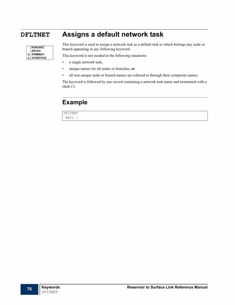
76 Keywords Reservoir to Surface Link Reference ManualDFLTNET
DFLTNET Assigns a default network taskThis keyword is used to assign a network task as a default task to which belongs any node or branch appearing in any following keyword.
This keyword is not needed in the following situations:
• a single network task,
• unique names for all nodes or branches, or
• all non-unique node or branch names are referred to through their composite names.
The keyword is followed by one record containing a network task name and terminated with a slash (/).
Example
RUNSPECPROPS
x SUMMARYx SCHEDULE
DFLTNETNET1 /

Reservoir to Surface Link Reference Manual KeywordsDFLTRES
77
DFLTRES Assigns a default reservoir taskThis keyword is used to assign a reservoir task as a default task to which belongs any well or group appearing in any following keyword.
This keyword is not needed in the following situations:
• a single reservoir task,
• unique names for all wells or groups, or
• all non-unique well or group names are referred to through their composite names.
The keyword is followed by one record containing a reservoir task name and terminated with a slash (/).
Example
RUNSPECPROPS
x SUMMARYx SCHEDULE
DFLTRESRES2 /

78 Keywords Reservoir to Surface Link Reference ManualECHO
ECHO Switches echo output onThe keyword turns on the echoing of the input file to the PRINT file at the start of the run. This echoing may be disabled using NOECHO, for example when entering large machine generated input files.
The default status for echoing is on. You can set this to off using NOECHO.
ECHO is normally only required, therefore, to turn echoing back on after a NOECHO keyword.
ECHO and NOECHO may be specified in any section, and any number of times in an input file.
x RUNSPECx PROPSx SUMMARYx SCHEDULE

Reservoir to Surface Link Reference Manual KeywordsEND
79
END Logical end of input fileThis keyword terminates the input of data.
The END keyword need not be the actual end of the input file. However, if no END keyword is provided, one is generated at the end of the input data file.
END has no arguments.
RUNSPECx PROPS
SUMMARYSCHEDULE

80 Keywords Reservoir to Surface Link Reference ManualENDFLUID
ENDFLUID End of a fluid definitionThis keyword terminates a FLUID sub-section. ENDFLUID has no arguments.
The keyword is only needed for the last FLUID in the PROPS section.RUNSPEC
x PROPSSUMMARYSCHEDULE

Reservoir to Surface Link Reference Manual KeywordsENDINC
81
ENDINC Logical end of include fileThe ENDINC keyword terminates the input of data from an INCLUDE file, returning control to the reading of the main file.
This keyword should not normally be entered, as an ENDINC is generated automatically at the end of the included file. It may, however, be used to end the reading of an included file before the actual end of file.
x RUNSPECx PROPSx SUMMARYx SCHEDULE

82 Keywords Reservoir to Surface Link Reference ManualENDWHEN
ENDWHEN End the set of keywords following a WHEN keywordThis keyword terminates the set of keywords following WHEN. ENDWHEN has no arguments.
RUNSPECPROPSSUMMARY
x SCHEDULE

Reservoir to Surface Link Reference Manual KeywordsEOS
83
EOS Specify which equation of state is to be usedThis keyword selects the equation of state corresponding to a FLUID. The keyword is followed by a single argument, the first letter of which is significant.
The possible options are:
PR: Peng-Robinson
RK: Redlich-Kwong
SRK: Soave-Redlich-Kwong
• DEFAULT: Peng-Robinson
A slight modification to the Peng-Robinson equation is available, by using PRCORR.
Note The FLUID number should be previously set using FLUID.
Examples
RUNSPECx PROPS
SUMMARYSCHEDULE
EOSPR /

84 Keywords Reservoir to Surface Link Reference ManualFEDIMS
FEDIMS Field events functionality dimensionsThis keyword is used to enter the dimensions needed for the field events functionality.
The keyword should be followed by one record containing the following items and terminated with a slash (/).
1 Maximum number of WHEN keywords in a data set.
• DEFAULT: 1
2 Maximum number of conditions entered with CONDLIST and CONDWHEN.
• DEFAULT: 1
3 Maximum number of lists entered with LIST.
• DEFAULT: 1
4 Maximum number of lines in the control part of a WHEN keyword.
• DEFAULT: 10Required and should be defaulted.
5 Maximum number of elements in a quantity. See CONDLIST and CONDWHEN for the definition of an element.
• DEFAULT: 1
Required and should be defaulted.
6 Maximum nesting level allowed in a quantity. See CONDLIST and CONDWHEN for details.
• DEFAULT: 1
•
7 Maximum number of logical expressions in a CONDLIST or CONDWHEN keyword.
• DEFAULT: 1
8 Maximum number of sorting criteria in a LIST keyword.
• DEFAULT: 1
Example
x RUNSPECPROPSSUMMARYSCHEDULE
FEDIMS2 4 2 50 4* /

Reservoir to Surface Link Reference Manual KeywordsFLUID
85
FLUID Fluid definitionThis keyword starts a new fluid definition. The keyword is followed by a record containing one integer (the fluid number) and terminated with a slash (/).
• DEFAULT: 1
The FLUID entered first is defaulted as the super set of components. Keywords following this FLUID keyword belong to the current FLUID. This continues until the program:
• encounters another FLUID keyword, or
• encounters ENDFLUID.
The last fluid in the PROPS section should be terminated with ENDFLUID.
ENDFLUID is optional for other fluids.
ExampleThis keyword defines a new fluid and assigns it with 9 as a number:
RUNSPECx PROPS
SUMMARYSCHEDULE
FLUID9 /

86 Keywords Reservoir to Surface Link Reference ManualGCONEXTN
GCONEXTN Control group rate by external network automatic chokesThe keyword specifies whether rate constraints across an automatic choke should be handled by the standard methods of group control in the reservoir simulator or by applying pressure losses across an automatic at a nominated branch in the surface network. The keyword is only needed if:
• there is a surface network present, and
• rate constraints for one or more groups are handled by automatic chokes in the network.
By default, group production and injection rate constraints applied in both the controller and ECLIPSE are handled by ‘guide rate’ group control. A rate target applied at a group is shared among its subordinate groups or wells in proportion to their guide rates. You can set the guide rates yourself to control how the target rate is shared between them; otherwise it defaults to their potentials. This method is physically equivalent to applying a separate choke at each well, as in general the wells operate at their share of the group rate target (unless they are prevented by another constraint).
External network chokes provide an alternative method of applying group rate constraints. The controller passes the group rate target over to a nominated branch in the surface network, and the network task adjusts the pressure drop across an automatic choke to make the flow rate meet the target. If the wells have insufficient potential to meet the target, there is a zero pressure drop across the choke and the flow rate will be less than the target. The wells are controlled by the back pressure of the network.
The keyword is followed by a set of records, each containing the following items terminated with a slash (/). The set of records must be terminated with a blank record containing just a slash.
1 Group name
See "Special characters" on page 20 and "Defaulting tasks" on page 21 for details about naming conventions.
Note The asterisk (*) character cannot be used to refer to several groups in this keyword.
2 The type of rate constraint to which the following instruction applies
PROD Production rate constraints
WINJ Water injection rate constraints
GINJ Gas injection rate constraints
3 Method of applying the rate constraint for this group
EXT The rate constraint is applied using an automatic choke in a surface network
INT The rate constraint is applied using the standard method of group control
• DEFAULT: EXT
4 The name of the network branch where the automatic choke is to be located
See "Special characters" on page 20 and "Defaulting tasks" on page 21 for details about naming conventions.
Note The asterisk (*) character cannot be used to refer to several nodes in this keyword.
RUNSPECPROPSSUMMARY
x SCHEDULE

Reservoir to Surface Link Reference Manual KeywordsGCONEXTN
87
This keyword is required if EXT is entered in item 3. An automatic choke must be defined in the network at this node.
Any groups in the ECLIPSE 100 or ECLIPSE 300 tasks not specified in this keyword use the group control method (guide rate control or prioritization) as instructed in the input data for the task.
Caution In the case of the rate a group GR1 subordinate to a group GR2. If the rate constraints of both groups are to be handled by applying pressure losses at nominated chokes in the network, the answer of group GR1 to higher level control should be NO (item 8 of GCONPROD for example)
ExampleGCONEXTNPLAT-A@RES1 PROD EXT NOD-A@NET1 /PLAT-A@RES1 GINJ EXT GINJ-A@NET2 /PLAT-B@RES1 PROD EXT NOD-B@NET1 //

88 Keywords Reservoir to Surface Link Reference ManualGCONINJE
GCONINJE Injection rate controls or limits for groupsThis keyword specifies the injection targets and limits for groups (Global groups defined using GRUPTREE or ECLIPSE groups).
When applied to ECLIPSE groups, the keyword performs exactly the same job as the ECLIPSE keyword GCONINJE. See the ECLIPSE Reference Manual for further information.
The following description of the keyword applies to groups belonging to the global tree (using GRUPTREE).
The keyword is followed by any number of records, each containing the following items of data, and each terminated with a slash (/).
The records may be terminated at any item after item 1. The remaining items assume their default values. Default values can be specified before the slash by a null repeat count of the form n*, where n is the number of consecutive items to be defaulted.
The set of records must end with a blank record, containing only a slash (/).
1 Group name.
See "Special characters" on page 20 and "Defaulting tasks" on page 21 for details about naming conventions.
2 Phase to which the following controls or limits apply
WATER Water injection controls.
GAS Gas injection controls.
When running in compositional mode, the nature of the injected gas must also be specified with GINJGAS, unless the group is under control of a higher level group with gas injection controls where the injection fluid is defined.
Injection controls and limits can be applied to one or more phases in any group. A separate data record is needed for each phase.
3 Injection rate control mode
NONE No immediate control of injection rate.
RATE The group or field surface injection rate of the phase in item 2 is controlled to meet the target specified in item 4.
RESV The group or field reservoir volume injection rate of the phase in item 2 is controlled so that the total reservoir volume injection rate of the group or field meets the target specified in item 5.
REIN The group or field surface injection rate of the phase in item 2 is controlled to equal the group or field production rate of the phase times the re-injection fraction specified in item 6.
VREP The group or field reservoir volume injection rate of the phase in item 2 is controlled so that the total reservoir volume injection rate of the group or field equals its production voidage rate times the voidage replacement fraction specified in item 7.
FLD The group is immediately under control from a higher level group or the field, injecting its share of the higher group’s or field’s target rate, according to its guide rate (which must be set in items 9 and 10 in this keyword).
• DEFAULT: NONE
RUNSPECPROPSSUMMARY
x SCHEDULE

Reservoir to Surface Link Reference Manual KeywordsGCONINJE
89
4 Surface injection rate target or upper limit for the phase in item 2
• UNITS: sm3/day (METRIC), stb/day for oil or water (FIELD), Mscf/day for gas (FIELD), sm3/day (PVT-M)
• DEFAULT: No target or limit
5 Total reservoir volume injection rate target or upper limit
If a non-default value is specified here, the phase in item 2 is declared the top-up phase. Its target or limiting reservoir volume injection rate is equal to the value specified here minus the reservoir volume injection rate of the other phases. The phase injection rate is calculated to top up the total group or field injection to the required reservoir volume rate, after allowing for any injection of the other phases.
• UNITS: rm3/day (METRIC), b/day (FIELD), m3/day (PVT-M)
• DEFAULT: No target or limit
Note There can be only one top-up phase at any given time in the simulation run.
6 re-injection fraction target or upper limit for the phase in item 2.
The re-injection fraction is applied to the group or field production rate of the phase in item 3.
The re-injection fraction can be applied to the production rate of a different group by entering the required group’s name in item 11.
• DEFAULT: No target or limit
7 Total voidage replacement fraction target or upper limit
If a non-default value is specified here, the phase in item 2 is declared the ‘top-up’ phase. Its target or limiting reservoir volume injection rate is equal to the value specified here times the group or field production voidage rate, minus the reservoir volume injection rate of the other phases. The phase injection rate is calculated to ‘top up’ the total group or field injection to the required voidage replacement fraction, after allowing for any injection of the other phases. There can be only one ‘top-up’ phase at any given time in the simulation run.
The voidage replacement fraction can be applied to the reservoir volume production rate of a different group by entering the required group’s name in item 12.
• DEFAULT: No target or limit
8 Is the group free to respond to a higher level injection rate target?
NO The group injects at its own capacity or target irrespective of any higher level rate target or limit
This item is ignored if the data record applies to the FIELD.
• DEFAULT: NO
9 Group’s injection guide rate for the phase in item 2, a dimensionless number governing the group’s share of a higher level injection target
See details in GMASTIGR.
This item is ignored if the data record applies to the FIELD.
• DEFAULT: No fixed guide rate
10 Definition of the guide rate in item 9.
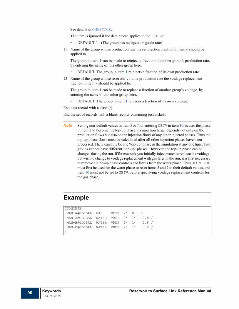
90 Keywords Reservoir to Surface Link Reference ManualGCONINJE
See details in GMASTIGR.
The item is ignored if the data record applies to the FIELD.
• DEFAULT: ' ' (The group has no injection guide rate)
11 Name of the group whose production rate the re-injection fraction in item 6 should be applied to.
The group in item 1 can be made to reinject a fraction of another group’s production rate, by entering the name of this other group here.
• DEFAULT: The group in item 1 reinjects a fraction of its own production rate
12 Name of the group whose reservoir volume production rate the voidage replacement fraction in item 7 should be applied to.
The group in item 1 can be made to replace a fraction of another group’s voidage, by entering the name of this other group here.
• DEFAULT: The group in item 1 replaces a fraction of its own voidage.
End data record with a slash (/).
End the set of records with a blank record, containing just a slash.
Note Setting non-default values in item 5 or 7, or entering NETV in item 10, causes the phase in item 2 to become the top-up phase. Its injection target depends not only on the production flows but also on the injection flows of any other injected phases. Thus the top-up phase flows must be calculated after all other injection phases have been processed. There can only be one ‘top-up’ phase in the simulation at any one time. Two groups cannot have different ‘top-up’ phases. However, the top-up phase can be changed during the run. If for example you initially inject water to replace the voidage, but wish to change to voidage replacement with gas later in the run, it is first necessary to remove all top-up phase controls and limits from the water phase. Thus GCONINJE must first be used for the water phase to reset items 5 and 7 to their default values, and item 10 must not be set to NETV, before specifying voidage replacement controls for the gas phase.
ExampleGCONINJEMAN-A@GLOBAL GAS REIN 2* 0.5 /MAN-A@GLOBAL WATER VREP 2* 1* 0.8 /MAN-B@GLOBAL WATER VREP 2* 1* 0.8 /MAN-C@GLOBAL WATER VREP 2* 1* 0.8 //

Reservoir to Surface Link Reference Manual KeywordsGCONPROD
91
GCONPROD Production rate controls or limits for groupsThis keyword specifies the production targets and limits for groups (Global groups defined using GRUPTREE or ECLIPSE groups).
When applied to ECLIPSE groups, the keyword performs exactly the same job as the ECLIPSE keyword GCONPROD. See the ECLIPSE Reference Manual for further information.
The following description of the keyword applies to groups belonging to the global tree (using GRUPTREE).
The keyword is followed by any number of records, each containing the following items of data, and each terminated with a slash (/).
The records may be terminated at any item after item 1. The remaining items assume their default values. Default values can be specified before the slash by a null repeat count of the form n*, where n is the number of consecutive items to be defaulted.
The set of records must end with a blank record, containing only a slash (/).
1 Group name.
See "Special characters" on page 20 and "Defaulting tasks" on page 21 for details about naming conventions.
2 Production rate control mode
NONE No immediate control of production rate
ORAT Group or field oil production rate is controlled to meet the target specified in item 3
WRAT Group or field water production rate is controlled to meet the target specified in item 4
GRAT Group or field gas production rate is controlled to meet the target specified in item 5
LRAT Group or field liquid production rate is controlled to meet the target specified in item 6
RESV Group or field reservoir fluid volume production rate is controlled to meet the target specified in item 14
FLD Group is immediately under control from a higher level group or the field, producing its share of the higher group’s or field’s target rate, according to its guide rate (which must be set in items 9 and 10 in this keyword).
• DEFAULT: NONE
3 Oil production rate target or upper limit
• UNITS: sm3/day (METRIC), stb/day (FIELD), sm3/day (PVT-M)
• DEFAULT: No target or limit
4 Water production rate target or upper limit
• UNITS: sm3/day (METRIC), stb/day (FIELD), sm3/day (PVT-M)
• DEFAULT: No target or limit
5 Gas production rate target or upper limit
• UNITS: sm3/day (METRIC), Mscf/day (FIELD), sm3/day (PVT-M)
• DEFAULT: No target or limit
RUNSPECPROPSSUMMARY
x SCHEDULE

92 Keywords Reservoir to Surface Link Reference ManualGCONPROD
6 Liquid production rate target or upper limit
• UNITS: sm3/day (METRIC), stb/day (FIELD), sm3/day (PVT-M)
• DEFAULT: No target or limit
7 Procedure on exceeding a maximum rate limit
RATE Control group or field production rate to equal the violated upper limit)
• DEFAULT: RATE
8 Is the group free to respond to a higher level production rate target?
NO the group produces at its own capacity or target irrespective of any higher level rate target
This item is ignored if the control data record applies to the FIELD.
• DEFAULT: NO
9 Group’s production guide rate
A dimensionless number governing the group’s share of a higher level production rate target.
See details in keyword GMASTPGR.
This item is ignored if the data record applies to the FIELD.
• DEFAULT: No fixed guide rate
10 Definition of the group's guide rate in item 9
See details in keyword GMASTPGR.
The item will be ignored if the data record applies to the FIELD.
• DEFAULT: ' ' (The group has no production guide rate)
11 Procedure on exceeding the water rate limit in item 4
The choices are as defined in item 7.
If this item is defaulted, the procedure specified in item 7 is applied.
12 Procedure on exceeding the gas rate limit in item 5
The choices are as defined in item 7.
If this item is defaulted, the procedure specified in item 7 is applied.
13 Procedure on exceeding the liquid rate limit in item 6
The choices are as defined in item 7.
If this item is defaulted, the procedure specified in item 7 is applied.
14 Reservoir fluid volume production rate target or upper limit
The procedure on exceeding this limit is always RATE.
• UNITS: rm3/day (METRIC), rb/day (FIELD), rm3/day (PVT-M)
• DEFAULT: No target or limit.
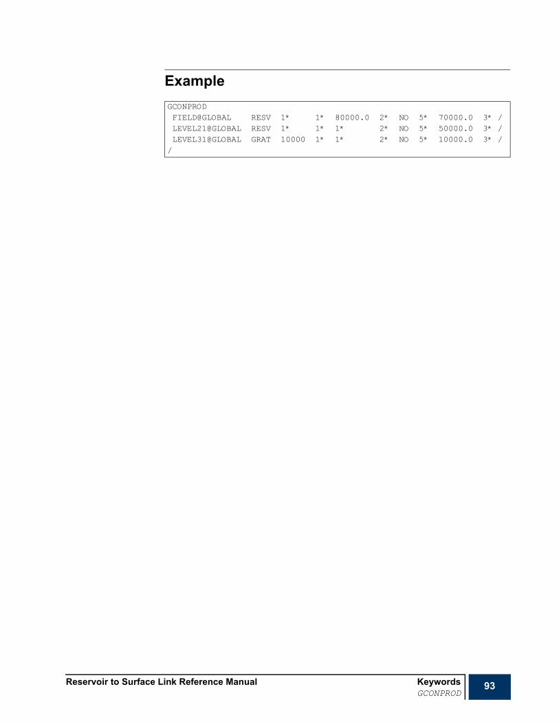
Reservoir to Surface Link Reference Manual KeywordsGCONPROD
93
ExampleGCONPRODFIELD@GLOBAL RESV 1* 1* 80000.0 2* NO 5* 70000.0 3* /LEVEL21@GLOBAL RESV 1* 1* 1* 2* NO 5* 50000.0 3* /LEVEL31@GLOBAL GRAT 10000 1* 1* 2* NO 5* 10000.0 3* //

94 Keywords Reservoir to Surface Link Reference ManualGGASQUAL
GGASQUAL Assign a gas quality or calorific value target to a reservoir coupling global groupThe keyword specifies allows the user to specify a gas quality or calorific value target to a global group. The keyword may only be used:
• to assign a gas quality or calorific value target to a single group in the global group tree.
• in conjunction with a gas-based target imposed using GCONPROD.
• if the target group has at least two subordinate global groups whose gas qualities or calorific values span the target value.
The keyword is followed by a set of records, each containing the following items terminated with a slash (/). The set of records must be terminated with a blank record containing just a slash.
1 Group name
Note The asterisk (*) character cannot be used as a wild card to refer to several groups in this keyword.
2 The type of rate constraint to which the following instruction applies
CVAL Calorific value
GQUA Gas quantity
3 Target value
Depending on the value selected in item 2, this will be either a calorific value or a gas quality.
• UNITS: Calorific value; KJ/SM3 (METRIC), BTU/MSCF (FIELD),
• UNITS: Gas Quality; KJ/kg.Mole (METRIC), BTU/lb.Mole (FIELD),
Example
RUNSPECPROPSSUMMARY
x SCHEDULE
GGASQUALEXPORT GQUA 50 //
Reservoir to Surface Link Reference Manual KeywordsGINJGAS
95
GINJGAS Specify the nature of the injected gas in a groupThis keyword is used to specify the nature of the gas injected by a group. The keyword is followed by any number of records each containing up to 6 items and terminated with a slash (/). The set of records should be terminated with a blank record containing just a slash.
Note This keyword cannot be used unless the option COMPOS is employed (item 3 of RUNMODE), otherwise an error message is displayed, and the run stops.
1 Group name
See "Special characters" on page 20 and "Defaulting tasks" on page 21 for details about naming conventions.
The nature of the injected gas in the group’s subordinates is also set.
Note Groups defined in this item must all belong to the same task (or global group control tree).
2 Nature of injected gas
STREAM The mole fraction of the injected fluid is defined using WELLSTRE. The name of the stream must be entered in item 4.
GV The injected fluid is to be taken from the vapor production of a nominated group. The name of the group must be entered in item 4.
3 Gas source.
Required but not used 4 1*
5 The stage of the separator that defines the fluid composition for injection
• DEFAULT: use vapor from the whole separator as injection fluid.
Note This keyword does not set the separator details at the group from which gas is taken. This should be done by associating a separator to the appropriate group using SETSEP. The use of this keyword might only be needed in the case of more than one separator to switch from the defaulted separator.
ExampleThe composition of the vapor produced from the last stage of the associated separator at groupEXPORT belonging to the global tree is set as the composition of the injected gas in the group MAN-C of the global tree.
RUNSPECPROPSSUMMARY
x SCHEDULE
GINJGASMAN-C@GLOBAL GV EXPORT@GLOBAL //
96 Keywords Reservoir to Surface Link Reference ManualGLIFTLIM
GLIFTLIM Maximum group capacity for artificial liftThe keyword can be used to limit the number of wells that are automatically switched to artificial lift. Limits can be set for individual groups or the field as a whole.
When applied to ECLIPSE groups, the keyword performs exactly the same job as the ECLIPSE keyword GRATLIM. See the ECLIPSE Reference Manual for further information.
The keyword is followed by any number of records, each containing the following items of data, and each terminated with a slash (/). The set of records must end with a blank record, containing only a slash (/).
1 Group name to several groups in one record.
See "Special characters" on page 20 and "Defaulting tasks" on page 21 for details about naming conventions.
2 Maximum total lift capacity.
This acts as a limit on the sum of the artificial lift quantity (ALQ) values of all subordinate open producers multiplied by their efficiency factors. If the ALQ refers to the pump power, this item limits the total pump power that can be applied in the group. For gas lift, if the ALQ refers to the lift gas injection rate, this item limits the group's total lift gas injection rate.
If the item is defaulted or set to zero, this limit will not be applied.
Maximum number of wells on artificial lift. This acts as a limit on the number of subordinate open producers that have a non-zero value for their artificial lift quantity.
If the item is defaulted or set to zero, this limit is not applied.
End the data record with a slash (/).
End the set of records with a blank record, containing just a slash.
Example
GLIFTLIMRes1@PLAT-A 800.0 /Res1@PLAT-B 1* 20 //

Reservoir to Surface Link Reference Manual KeywordsGLIFTOPT
97
GLIFTOPT Group lift gas limits for gas lift optimizationThe GLIFTOPT keyword may be used to set group lift gas supply limits for the Gas Lift Optimization facility.
When applied to ECLIPSE groups, the keyword performs exactly the same job as the ECLIPSE keyword GRATLOPT. See the ECLIPSE Reference Manual for further information.
The keyword is followed by any number of records, each containing the following items of data
and terminated with a slash (/). The set of records must end with a blank record, containing only
a slash.
1 Group name or group name root, or FIELD to set a lift gas supply limit for the field.
A group name root, enclosed in quotes and ending with an asterisk (*), can be used to refer to several groups in one record.
2 Maximum lift gas supply limit for the group
The group's lift gas supply is the sum of the lift gas injection rates of its subordinate wells or groups, multiplied by the wells' or groups' efficiency factors.
A default or negative value implies there is no limit for the group.
• UNITS: sm3/day (METRIC), Mscf/day (FIELD), scc/hr (LAB), sm3/day (PVT-M)
3 Maximum total gas rate for the group
The group's total gas rate is the sum of the lift gas plus the gas produced from the formation for each subordinate well or group, multiplied by the well's or group's efficiency factor.
Lift gas increments are not allocated to wells below this group if they would cause this limit
to be exceeded.
A default or negative value implies there is no limit for the group.
• UNITS: sm3/day (METRIC), Mscf/day (FIELD), scc/hr (LAB), sm3/day (PVT-M)
End the data record with a slash (/).
End the set of records with a blank record containing just a slash (/).
Example
GLIFTOPT-- group max lift max total-- name gas rate gas rate-- SM3/DAY'Res1@PL-*' 1E6 //
98 Keywords Reservoir to Surface Link Reference ManualGMASTIGR
GMASTIGR Injection guide rates for master groupsThe keyword is used in Reservoir Coupling simulations (see GRUPTREE), to set the injection guide rate for the master groups. Each master group must have an injection guide rate for each fluid that it injects, which governs its share of any global injection rate target imposed on a higher level group in the global tree. The injection target is shared among these groups in proportion to their guide rates. The rate target is then communicated to the corresponding slave group in one of the reservoir simulation tasks. If the group cannot inject its guide rate share of the target, it injects what it can and the remaining master groups make up the shortfall, provided that they have sufficient capacity.
Note This keyword cannot be used unless the option RESCUP is employed (item 2 of RUNMODE); otherwise the run stops.
The keyword is followed by a set of records, each containing the following items terminated with a slash (/). The set of records must be terminated with a blank record containing just a slash.
1 The name of the master group
2 The fluid for which the injection guide rate is being defined
WATER or GAS
If the group injects both of these fluids, you may define a separate guide rate for each fluid by entering two records.
3 Value of the group’s injection guide rate, defined for the quantity in item 4
Set this to a positive value if you wish to give the group a fixed injection guide rate for the fluid in item 2.
This item will be ignored if item 4 contains VOID or NETV.
4 Definition of the group’s injection guide rate for the fluid in item 2
RATE The guide rate applies to group’s surface injection rate (so the surface injection rate target is in proportion to the guide rate).
RESV The guide rate applies to group’s reservoir volume injection rate (so the reservoir volume injection target is in proportion to the guide rate).
VOID The guide rate is set at the beginning of each time step equal to the group’s voidage production rate. This setting can be used to apportion an injection target between groups in proportion to their voidage production rates.
NETV The guide rate is set at the beginning of each time step equal to the group’s net voidage rate (that is its voidage production rate minus the reservoir volume injection rate of any other fluids). This setting can be used to apportion an injection target between groups in proportion to their top-up needs for voidage replacement.
• DEFAULT: RATE
RUNSPECPROPSSUMMARY
x SCHEDULE

Reservoir to Surface Link Reference Manual KeywordsGMASTIGR
99
ExampleGMASTIGRMAN-A WATER 1.0 RATE /MAN-B WATER 1.0 RATE /MAN-B WATER 1.0 RATE //

100 Keywords Reservoir to Surface Link Reference ManualGMASTPGR
GMASTPGR Production guide rates for master groupsThe keyword is used in Reservoir Coupling simulations (see GRUPTREE), to set the production guide rate for the master groups. Each master group must have a guide rate, which governs its share of any global production rate target imposed on a higher level group in the global tree. The production target is shared among these groups in proportion to their guide rates. (If the guide rate has been defined for a different phase from the one that has the control target, the controller transforms the guide rate to the controlled phase, using the group’s latest production ratios.) The rate target is then communicated to the corresponding slave group in one of the reservoir simulation tasks. If the group cannot produce its guide rate share of the target, it produces what it can and the remaining master groups make up the shortfall, provided that they have sufficient capacity.
Note This keyword cannot be used unless the option RESCUP is employed (item 2 of RUNMODE), otherwise the run stops.
The keyword is not mandatory. Master groups that do not have their guide rate defined assume a default guide rate equal to their production potential.
The keyword is followed by a set of records, each containing the following items terminated with a slash (/). The set of records must be terminated with a blank record containing just a slash.
1 The name of the master group
2 Value of the group’s guide rate, defined for the quantity in item 3
Set this to a positive value if you wish to give the group a fixed guide rate for a particular phase (OIL, WAT, GAS, LIQ, RES or WGA).
This item is ignored if item 3 contains POTN or FORMn.
3 Definition of the group’s production guide rate
OIL The group’s production guide rate applies to the oil phase.
WAT The group’s production guide rate applies to the water phase.
GAS The group’s production guide rate applies to the gas phase.
LIQ The group’s production guide rate applies to the liquid phase.
RES The group’s production guide rate applies to its reservoir fluid volume rate (so its voidage rate is in proportion to its guide rate).
POTN The group’s guide rate is set at the beginning of each time step equal to the group’s production potential, which is the sum of the production potentials of the wells subordinate to its corresponding slave group.
FORMn The group's guide rate is calculated at specified intervals from a formula involving its production potentials, defined with the GRFORMS or GUIDERAT. This option can be used, for example, to decrease the contribution from groups with high GOR or water cut. The ‘n’ stands for an integer that indicates the number of the formula to use, in cases where multiple formulae have been defined in GRFORMS. If the integer is omitted, the first formula is used for the group’s production guide rate.
• DEFAULT: POTN
RUNSPECPROPSSUMMARY
x SCHEDULE
Reservoir to Surface Link Reference Manual KeywordsGMASTPGR
101
ExampleGMASTPGRLEVEL31 1* FORM3 /LEVEL32 1* FORM3 /LEVEL22 1* FORM3 /LEVEL23 1* FORM3 //

102 Keywords Reservoir to Surface Link Reference ManualGMFVD
GMFVD Stock tank gas mole fraction with respect to surface oil density table The data comprises a table of stock tank gas mole fraction with respect to surface oil density data. Each table consists of columns of data, and is terminated with a slash (/).
Column:
1 Surface oil density values.
The values should increase monotonically down the column.
• UNITS: kg/m3 (METRIC), lb/ft3 (FIELD), kg/m3 (PVT-M)
2 to
The corresponding values of , the stock tank gas mole fractions. The mole fractions specified must add up to unity, and the program checks that this is the case.
The maximum number of GMVFD tables as well as the maximum number of rows in a table are set using MFVPDDIM. The number of components should be previously set using NCOMPS.
Note The FLUID number and the number of components corresponding to this FLUID should be previously set using FLUID and NCOMPS, respectively.
Example
RUNSPECx PROPS
SUMMARYSCHEDULE
GMFVD39.0426 0.403644838
0.2377661280.0737193490.0761755070.1123043040.087660640.0085149390.0002127681.53E-06
41.6746 0.1255756310.0095562780.0091786930.0506798750.1883966970.4719001970.1412841320.0034252913.21E-06
/
Nc 1+
Nc 1+
yi Nc
Reservoir to Surface Link Reference Manual KeywordsGRFORMS
103
GRFORMS Guide rate formulaeThis keyword can be used to specify general formulae for calculating production guide rates for group control. The formulae can subsequently be used to calculate the production guide rates for groups having a guide rate definition of FORMn in item 3 of GMASTPGR (where ‘n’ is an integer that refers to the desired formula specified in this keyword).
Note This keyword cannot be used unless the option RESCUP is employed (item 2 of RUNMODE), otherwise the run stops.
In Reservoir Coupling runs, the global production target is shared between the master groups in proportion to their guide rates. The GRFORMS keyword provides the option to define a set of formulae for the guide rates, expressing them as a function of the group production potentials for oil, water and gas. For example, it is possible to define a formula that makes the guide rate decrease as the water cut or GOR increases, thus decreasing the relative contribution from high water cut or GOR groups.
At the beginning of the next controller time step, the guide rates ( ) for a nominated phase is calculated from the formula
[EQ 5.1]
wherePOTp is the well’s or group’s potential flow rate of the nominated phase p,
A, B, C, D, E and F are user-supplied powers and coefficients,
R1 and R2 are ratios of phase potentials, which depend on the nominated phase p.
For the rest of the simulation, the guide rates are recalculated at the beginning of each time step that starts after a specified interval has elapsed from the previous guide rate calculation. The interval defaults to zero, giving a guide rate calculation at the beginning of each time step. However, a longer interval may be preferred if the guide rates oscillate due to rate-dependent coning, or alternatively a damping factor may be applied in item 3.
The denominator is not allowed to become negative. If the power D or F is negative, the ratio R1 or R2 is limited to be not less than 1.0E-6.
If the nominated phase p differs from the phase under group control, is converted into a guide rate for the controlled phase using the well’s or group’s production ratios at the beginning of the time step.
The GRFORMS keyword is followed by any number of records, each terminated with a slash (/). The set of records should be terminated with a blank record containing just a slash. The first record contains general information about guide rate calculation, while each of the remaining records contains the definition for a specific formula.
Record 1: General InformationRecord 1 contains three items that provide general information about guide rate calculation:
1 The minimum time interval between guide rate calculations
RUNSPECPROPSSUMMARY
x SCHEDULE
GRp
p
GRpPOTp( )A
B C R1( )D E R2( )F+ +
----------------------------------------------------=
GRp

104 Keywords Reservoir to Surface Link Reference ManualGRFORMS
The guide rates are calculated from the formula above at the beginning of each controller time step that starts after the specified interval has elapsed since the previous guide rate calculation.
A zero value causes the guide rates to be recalculated every controller time step. A longer interval may be preferred if the guide rates oscillate due to rate-dependent coning phenomena, or alternatively a damping factor may be applied in item 3.
• UNITS: days (METRIC), days (FIELD), days (PVT-M).
• DEFAULT: 0.0
2 Should the guide rates be allowed to increase?
YES Guide rates are allowed to increase if the formula results in a higher value (for example due to a reduced water cut or GOR).
NO The guide rate of the nominated phase is only allowed to decrease. If the formula results in a higher value than the current one, the value remains unchanged. (This option decreases the tendency for guide rates to oscillate due to rate-dependent coning phenomena.)
• DEFAULT: YES
3 Damping factor, GRDAMP
This must lie between 0.0 and 1.0. It provides a means (as an alternative to setting item 2 to NO) of damping guide rate oscillations that may result from rate-dependent water cut or GOR. Each time a new guide rate is calculated for a well or group, it is averaged with its previous value according to the formula
[EQ 5.2]
A damping factor of 1.0 allows the guide rates to change instantaneously with the phase potentials. As the damping factor reduces towards 0.0, the guide rates will be weighted increasingly towards their previous values, reducing any tendency to oscillate.
• DEFAULT: 1.0
Remaining RecordsUp to 50 records are allowed, each containing up to 8 items defining a guide rate formula.
1 Formula number: a positive integer.
2 The nominated phase p
OIL GRp is the oil phase guide rate.
The phase potential ratios are:
R1 = water-oil ratio (dimensionless)
R2 = gas-oil ratio
• UNITS: sm3/sm3 (METRIC), scc/scc (LAB), sm3/sm3 (PVT-M)
LIQ GRp is the liquid phase guide rate. (oil + water).
The phase potential ratios are:
R1 = water cut (dimensionless)
GRused GRDAMP GRcalculated 1 GRDAMP–( ) GRprevious+=

Reservoir to Surface Link Reference Manual KeywordsGRFORMS
105
R2 = gas-liquid ratio
• UNITS: sm3/sm3 (METRIC), scc/scc (LAB), sm3/sm3 (PVT-M)
GAS GRp is the gas phase guide rate.
The phase potential ratios are:
R1 = water-gas ratio
R2 = oil-gas ratio
• UNITS: sm3/sm3 (METRIC), scc/scc (LAB), sm3/sm3 (PVT-M)
RES GRp is the reservoir fluid volume guide rate.
The phase potential ratios are:
R1 = water-oil ratio (dimensionless)
R2 = gas-oil ratio
• UNITS: sm3/sm3 (METRIC), scc/scc (LAB), sm3/sm3 (PVT-M)
NONE The general formula is not applied.
The well guide rates is set equal to their production potentials at every time step, with no damping, just as if this keyword had not been entered. An error is flagged if any group requires its guide rate to be calculated from the formula.
• DEFAULT: NONE
3 The power A of the phase potential rate.
This must lie between 3.0 and -3.0.
• DEFAULT: 0.0
4 The constant B on the denominator.
This must not be negative.
• DEFAULT: 0.0
5 The coefficient C of the phase ratio R1.
• DEFAULT: 0.0
6 The power D of the phase ratio R1.
This must lie between 3.0 and -3.0.
• DEFAULT: 0.0
7 The coefficient E of the phase ratio R2.
• DEFAULT: 0.0
8 The power F of the phase ratio R2.
This must lie between 3.0 and -3.0.
• DEFAULT: 0.0
The keyword affects production guide rates only. Guide rates for injection wells are still by default set equal to their potential injection rates.

106 Keywords Reservoir to Surface Link Reference ManualGRFORMS
ExamplesIn this example, keyword GRFORMS defines two guide rate formulae for the following purpose:
1 To set the liquid phase guide rates equal to the liquid phase potentials at low water cut, and biased against high water cut wells, with a damping factor of 0.1
2 To set the oil phase guide rates equal to the oil phase potentials, to be recalculated after 100-day intervals
Guide rates for both formulae will be updated every 100 days and they are not allowed to increase. A damping factor of 0.1 is used which allows the guide rates to be slightly weighted towards their previous values.
GRFORMS100 NO 0.11 LIQ 1.0 1.0 10.0 2.0 0.0 0.0 /2 OIL 1.0 1.0 //

Reservoir to Surface Link Reference Manual KeywordsGRUPIRT
107
GRUPIRT Set group injection rate target or limitThe keyword can be used to set or modify a group’s injection rate target or limit for a particular fluid. The group may be either a global group in the controller’s group hierarchy or a group declared in one of the coupled ECLIPSE tasks.
The keyword is followed by a set of records, each containing the following items terminated with a slash (/). The set of records must be terminated with a blank record containing just a slash.
1 Group name
See "Special characters" on page 20 and "Defaulting tasks" on page 21 for details about naming conventions.
2 The fluid for which the injection rate target or limit is being defined
WATER or GAS
If the group injects both of these fluids, you may input a separate target or limit for each fluid by entering two records.
3 Definition of the target or limit to be set or modified
RATE Injection rate at surface conditions
RESV Injection volumetric rate at reservoir conditions
REIN Re-injection fraction
VREP Voidage replacement fraction
4 Target or upper limiting rate for this quantity
The units depend upon the quantity selected. the appropriate units are listed in the documentation for GCONPROD and GCONINJE.
• DEFAULT: 1.0E20, which removes any target or limit for this quantity.
Example
RUNSPECPROPSSUMMARY
x SCHEDULE
GRUPIRTFIELD@GLOBAL GAS REIN 1.0 /FIELD@GLOBAL WATER VREP 1.0 /GR-A2@RES1 WATER RATE 8000 //
108 Keywords Reservoir to Surface Link Reference ManualGRUPMAST
GRUPMAST Identify master groups and corresponding slave groupsThe keyword is used in Reservoir Coupling simulations, where it identifies the master groups in the global tree (defined using GRUPTREE) and their slave group counterparts in the reservoir simulation tasks.
Note This keyword cannot be used unless the option RESCUP is employed (item 2 of RUNMODE) and GRUPTREE is used to define the global tree.
In reservoir coupling runs, the groups on the lowest level of the global tree must each be paired to a group in one of the reservoir simulation tasks. These groups are termed master groups while their counterparts in the reservoir tasks are termed slave groups. By means of this pairing of groups in the controller and the reservoir simulation tasks, the global constraints are applied to the individual reservoir models. The hierarchy of global groups in the controller should be defined with the GRUPTREE keyword.
Note The slave groups in the ECLIPSE tasks are identified in the controller’s input data. They do not need to be identified as slaves in the ECLIPSE input data. Do not use GRUPSLAV here. The controller cancels any constraints imposed on them from within the ECLIPSE input data, and make them unavailable for higher level group or field control, thus leaving them free to respond solely to the constraints communicated from R2SL. Do not impose constraints on any groups at higher level than the slaves in the ECLIPSE input data; the slave groups are not able to respond to these.
The GRUPMAST keyword is only needed if:
• the MANUMAP option is specified in RUNMODE item 1 and
• the master groups in the controller have different names as their slave group counterparts.
When GRUPMAST is not present in a Reservoir Coupling run, R2SL automatically defines all the groups at the bottom of the global tree (those with no children) as master groups and searches the ECLIPSE tasks for groups with corresponding names to define as their slaves. When GRUPMAST is present in a R2SL data set, it should be preceded by GRUPTREE.
The keyword is followed by a set of records, each containing the following items terminated with a slash (/). The set of records must be terminated with a blank record containing just a slash.
1 The name of the master group in the global tree
2 The name of the ECLIPSE 100 or 300 task to which the corresponding slave group belongs
3 The name of the slave group
4 The limiting fraction by which the group’s flow rate may change in a single timestep
• DEFAULT: infinity
A value may optionally be entered here to limit the fraction by which the group’s flow rate (that is the reservoir fluid volume production rate and its phase injection rates) can change over a single timestep. The controller does this by restricting the length of the synchronization timestep, based on the previous timesteps flow rate changes. The restriction takes place retrospectively, and the timestep is not chopped if a sudden rate change causes the limit to be exceeded.
RUNSPECPROPSSUMMARY
x SCHEDULE

Reservoir to Surface Link Reference Manual KeywordsGRUPMAST
109
If the slave groups flow rates change significantly over a single timestep, the group flow rate targets imposed in the controller may not be accurately obeyed. This is because the flow rate targets are apportioned among the master groups according to their slave groups flow capabilities at the start of each timestep, while the reported flows are those occurring at the end of the timestep. Reducing the limiting flow change fraction increases the accuracy of the group controls. However, it is also advisable to set a minimum timestep length that this restriction can impose (see RCMASTS), as the fractional flow changes can be large when the flows are small and wells are being opened or closed in the slave reservoirs.
Example The limiting fraction by which PLAT-B’s flow rate may change in a single timestep is 0.1 (10%). When this limit is hit, the controller time step will be reduced as discussed in "Multiple reservoirs synchronization" in the "Reservoir to Surface Link Technical Description".
GRUPMASTPLAT-A RES1 FIELD /PLAT-B RES2 FIELD 0.1 //
110 Keywords Reservoir to Surface Link Reference ManualGRUPPRT
GRUPPRT Set group production rate target or limitThe keyword can be used to set or modify a group’s production rate target or limit. The group may be either a global group in the controller’s group hierarchy or a group declared in one of the coupled ECLIPSE tasks.
The keyword is followed by a set of records, each containing the following items terminated with a slash (/). The set of records must be terminated with a blank record containing just a slash.
1 Group name
See "Special characters" on page 20 and "Defaulting tasks" on page 21 for details about naming conventions.
2 Definition of the target or limit to be set or modified
ORAT Oil rate
WRAT Water rate
GRAT Gas rate
LRAT Liquid rate
RESV Reservoir fluid volume rate
3 Target or upper limiting rate for this quantity
The units depend upon the quantity selected. the appropriate units are listed in the documentation for GCONPROD and GCONINJE.
• DEFAULT: 1.0E20, which removes any target or limit for this quantity.
Example
RUNSPECPROPSSUMMARY
x SCHEDULE
GRUPPRTPLAT-A@GLOBAL ORAT 15000 /PLAT-B@GLOBAL RESV 20000 /GR-A2@RES1 WRAT 8000 //

Reservoir to Surface Link Reference Manual KeywordsGRUPTARG
111
GRUPTARG Resets a group production rate target or limitThis keyword can be used to reset a group production rate target or limit within a coupled ECLIPSE task. The group control data should initially have been set using GCONPROD (for guide rate control) or GCONPRI (for prioritization). Refer to the ECLIPSE keyword documentation on GRUPTARG for more information.
The keyword is followed by any number of records, each containing the following items of data, and each terminated with a slash (/).
The set of records must end with a blank record, containing only a slash (/).
1 Group name or group name root
or FIELD (for field targets or limits)
A group name root, enclosed in quotes and ending with an asterisk (*), can be used to refer to several groups in one record.
2 Definition of the target or limit to be changed
ORAT Oil rate
WRAT Water rate
GRAT Gas rate
LRAT Liquid rate
CRAT Linearly combined rateECLIPSE 300 only WGRA Wet gas rate
RESV Reservoir fluid volume rateECLIPSE 300 only CVAL Calorific rate
PRBL Reservoir fluid volume production balancing fractionECLIPSE 300 only PBGS Surface gas volume production balancing fractionECLIPSE 300 only PBWS Surface water volume production balancing fraction
GUID Guide rate (see items 9 and 10 of the keyword GCONPROD).
The guide rate can only be set here if its definition has been set to OIL, WAT, GAS, LIQ, WGA or RES in item 10 of keyword GCONPROD.
3 New value of this quantity.
The units depend upon the quantity chosen. The appropriate units are listed in the specification for keyword GCONPROD.
If an oil, water, gas or liquid rate limit is specified, and the procedure on exceeding the corresponding rate limit has not been set in GCONPROD, the procedure is defaulted to RATE (for guide rate control).
• DEFAULT: No target or limit
End data record with a slash (/).
End the set of records with a blank record, containing just a slash.
RUNSPECPROPSSUMMARY
x SCHEDULE

112 Keywords Reservoir to Surface Link Reference ManualGRUPTARG
Example
GRUPTARGPLAT-A ORAT 15000 /PLAT-B RESV 20000 //

Reservoir to Surface Link Reference Manual KeywordsGRUPTREE
113
GRUPTREE Sets up group tree structure for group controlThe keyword is only needed in two situations:
Reservoir Coupling simulations, when there are two or more reservoir simulation tasks coupled by common production or injection constraints. Global groups must be defined in the controller to handle the common constraints.
The option RESCUP should be employed (item 2 of RUNMODE); otherwise, the run is stopped.
The groups on the lowest level of the global tree must each be paired to a group in one of the reservoir simulation tasks. These global groups are termed master groups while their counterparts in the reservoir tasks are termed slave groups. By means of this pairing of groups in the controller and the reservoir simulation tasks, the global constraints are applied to the individual reservoir models. See GRUPMAST for further details.
The group at the top of the tree cannot be a master group.
Groups that have other groups as children cannot also have wells. The GRUPTREE keyword is followed by any number of records, each containing the following items of data, and each terminated with a slash (/). The set of records must end with a blank record, containing only a slash (/).
1 Name of the child group
The “*” and “@” characters cannot be used to refer to several groups in this keyword. The task to which the group belongs is the current default task (assigned using DFLTRES).
2 Name of its parent group
The record declares the second group to be the parent of the first group.
The “*” and “@” characters cannot be used to refer to several groups in this keyword. The task to which the group belongs is the same as that of the child group.
A parent group may have several child groups, but each group can have only one parent.
Note The group at the top of the tree does not have necessarily to be called FIELD.
ExampleThis examples shows a typical use of the keyword to build a global group control tree.
RUNSPECPROPSSUMMARY
x SCHEDULE
GRUPTREE-- child parent
GR-A1 PLAT-A /GR-A2 PLAT-A /GR-B1 PLAT-B /GR-B2 PLAT-B /PLAT-A FIELD /PLAT-B FIELD /
/

114 Keywords Reservoir to Surface Link Reference ManualGUIDERAT
GUIDERAT Specify general formula for guide ratesThis keyword is similar to the ECLIPSE 100 or 300 keyword GUIDERAT. It can be used to specify a general formula for calculating production guide rate for group control. GRFORMS provides more flexibility than this keyword; its use is thus encouraged over GUIDERAT. The use of both GUIDERAT and GRFORMS in the same data set may result on data overwriting each other in some cases. This is because the formula defined with GUIDERAT is attributed a formula number equal to 1, which overwrites a previously defined formula with the same formula number using GRFORMS.
Note This keyword cannot be used unless the option RESCUP is employed (item 2 of RUNMODE), otherwise the run stops.
In Reservoir Coupling runs, the global production target is shared between the master groups in proportion to their guide rates. The GUIDERAT keyword provides the option to define a set of formulae for the guide rates, expressing them as a function of the group production potentials for oil, water and gas. For example, it is possible to define a formula that makes the guide rate decrease as the water cut or GOR increases, thus decreasing the relative contribution from high water cut or GOR groups.
At the beginning of the next controller time step, the guide rates ( ) for a nominated phase is calculated from the formula
[EQ 5.3]
wherePOTp is the well’s or group’s potential flow rate of the nominated phase p,
A, B, C, D, E and F are user-supplied powers and coefficients,
R1 and R2 are ratios of phase potentials, which depend on the nominated phase p.
For the rest of the simulation, the guide rates are recalculated at the beginning of each time step that starts after a specified interval has elapsed from the previous guide rate calculation. The interval defaults to zero, giving a guide rate calculation at the beginning of each time step. However, a longer interval may be preferred if the guide rates oscillate due to rate-dependent coning, or alternatively a damping factor may be applied in item 3.
The denominator is not allowed to become negative. If the power D or F is negative, the ratio R1 or R2 is limited to be not less than 1.0E-6.
If the nominated phase p differs from the phase under group control, is converted into a guide rate for the controlled phase using the well’s or group’s production ratios at the beginning of the time step.
The GUIDERAT keyword is followed by a line containing up to 10 items of data, terminated with a slash (/).
The items are:
1 The minimum time interval between guide rate calculations.
The guide rates are calculated from the formula above at the beginning of each time step that starts after the specified interval has elapsed since the previous guide rate calculation.
RUNSPECPROPSSUMMARY
x SCHEDULE
GRp
p
GRpPOTp( )A
B C R1( )D E R2( )F+ +
----------------------------------------------------=
GRp

Reservoir to Surface Link Reference Manual KeywordsGUIDERAT
115
A zero value causes the guide rates to be recalculated every time step. A longer interval may be preferred if the guide rates oscillate due to rate-dependent coning phenomena, or alternatively a damping factor may be applied in item 10.
• UNITS: days (METRIC), days (FIELD), days (PVT-M)
• DEFAULT: 0.0
2 The nominated phase p
OIL GRp is the oil phase guide rate.
The phase potential ratios are:
R1 = water-oil ratio (dimensionless)
R2 = gas-oil ratio
• UNITS: sm3/sm3 (METRIC), Mscf/stb (FIELD), sm3/sm3 (PVT-M)
LIQ GRp is the liquid phase guide rate (oil + water).
The phase potential ratios are:
R1 = water cut (dimensionless)
R2 = gas-liquid ratio
• UNITS: sm3/sm3 (METRIC), Mscf/stb (FIELD), sm3/sm3 (PVT-M)
GAS GRp is the gas phase guide rate.
The phase potential ratios are:
R1 = water-gas ratio
R2 = oil-gas ratio
• UNITS: sm3/sm3 (METRIC), Mscf/stb (FIELD), sm3/sm3 (PVT-M)
RES GRp is the reservoir fluid volume guide rate.
The phase potential ratios are:
R1 = water-oil ratio (dimensionless)
R2 = gas-oil ratio
• UNITS: sm3/sm3 (METRIC), Mscf/stb (FIELD), sm3/sm3 (PVT-M)
NONE The general formula is not applied.
The well guide rates is set equal to their production potentials at every time step, with no damping, just as if this keyword had not been entered. An error is flagged if any group requires its guide rate to be calculated from the formula.
• DEFAULT: NONE
3 The power A of the phase potential rate.
This must lie between 3.0 and -3.0.
• DEFAULT: 0.0
4 The constant B on the denominator.
This must not be negative.
• DEFAULT: 0.0

116 Keywords Reservoir to Surface Link Reference ManualGUIDERAT
5 The coefficient C of the phase ratio R1.
• DEFAULT: 0.0
6 The power D of the phase ratio R1.
This must lie between 3.0 and -3.0.
• DEFAULT: 0.0
7 The coefficient E of the phase ratio R2.
• DEFAULT: 0.0
8 The power F of the phase ratio R2.
This must lie between 3.0 and -3.0.
• DEFAULT: 0.0
9 Should guide rates be allowed to increase?
YES Guide rates are allowed to increase if the formula results in a higher value (for example due to a reduced water cut or GOR).
NO The guide rate of the nominated phase is only allowed to decrease. If the formula results in a higher value than the current one, the value remains unchanged. (This option decreases the tendency for guide rates to oscillate due to rate-dependent coning phenomena.)
• DEFAULT: YES
10 Damping factor, GRDAMP
This must lie between 0.0 and 1.0. It provides a means (as an alternative to setting item 9 to NO) of damping guide rate oscillations that may result from rate-dependent water cut or GOR. Each time a new guide rate is calculated for a well or group, it is averaged with its previous value according to the formula
[EQ 5.4]
A damping factor of 1.0 allows the guide rates to change instantaneously with the phase potentials. As the damping factor reduces towards 0.0, the guide rates will be weighted increasingly towards their previous values, reducing any tendency to oscillate.
• DEFAULT: 1.0
The keyword affects production guide rates only. Guide rates for injection wells are still by default set equal to their potential injection rates.
Example
Example 1To set the liquid phase guide rates equal to the liquid phase potentials at low water cut, and biased against high water cut wells, with a damping factor of 0.1:
GUIDERAT-- interval phase A B C D E F increase? damp
1* LIQ 1.0 1.0 10.0 2.0 0.0 0.0 NO 0.1 /
GRused GRDAMP GRcalculated 1 GRDAMP–( ) GRprevious+=

Reservoir to Surface Link Reference Manual KeywordsGUIDERAT
117
Example 2To set the oil phase guide rates equal to the oil phase potentials, to be recalculated after 100 day intervals:
GUIDERAT-- interval phase A B C D E F increase? damp
100 OIL 1.0 1.0 /

118 Keywords Reservoir to Surface Link Reference ManualINCLUDE
INCLUDE Include the contents of another named fileThe keyword should be followed by the name of a file from which input is to be taken. This file is opened, and read to the end of the file unless an ENDINC keyword is encountered. The file is then closed, and input resumed from the main file, starting from the next keyword after the INCLUDE keyword.
The INCLUDE file name may have up to 132 characters.
The data should be terminated by a slash (/).
Nested INCLUDE files are possible.
ExampleThis example causes the program to continue input from the file FLUID1.INC. At the end of that file, the program switches back to the next keyword in the current file.
x RUNSPECx PROPSx SUMMARYx SCHEDULE
INCLUDEFLUID1.INC /

Reservoir to Surface Link Reference Manual KeywordsKVALUES
119
KVALUES Use K-values for liquid-vapor phase equilibriumThis keyword requests that K-values be used to control liquid-vapor phase equilibrium. The actual K-values are entered using the KVTABLE keyword in the PROPS section.
The keyword has no arguments.
Note The FLUID number to which KVALUES belongs should be previously set using keyword FLUID.
RUNSPECx PROPS
SUMMARYSCHEDULE

120 Keywords Reservoir to Surface Link Reference ManualKVTDIMS
KVTDIMS K-values table dimensionsThis keyword is used to enter the dimensions of the K-values versus pressure tables.
The keyword should be followed by one record containing the following items and terminated with a slash (/).
Note This keyword cannot be used unless the option COMPOS is employed (item 2 of RUNMODE), otherwise an error message is displayed, and the run stops.
1 Maximum number of K-values versus pressure tables. The number of K-values versus pressure tables should be less than this maximum number.
• DEFAULT: 1
2 Maximum number of components in each table
• DEFAULT: the actual number of delumped components (super set of components) defined in item 1 of COMPDIMS.
3 Maximum number of rows per table
• DEFAULT: 50
Example
x RUNSPECPROPSSUMMARYSCHEDULE
KVTDIMS2 8 10 /
Reservoir to Surface Link Reference Manual KeywordsKVTABLE
121
KVTABLE K-values versus pressure tableThis keyword is used to enter a K-values versus pressure table. The table contains Nr rows each containing Nc+1 items:
1 item 1: pressure (pressure should increase monotonically with the number of rows).
• UNITS: barsa (METRIC), psia (FIELD), atma (PVT-M)
2 Items 2 to Nc: K-values of components 1, …, Nc.
Note The FLUID number and the number of components corresponding to this FLUID should be previously set using FLUID and NCOMPS, respectively.
Example
RUNSPECx PROPS
SUMMARYSCHEDULE
-- 7 components FLUIDKVTABLE3014.7 1.14 1.44 1.01 0.92 0.73 0.12 0.0415014.7 1.66 1.54 1.12 0.85 0.60 0.09 0.023 /

122 Keywords Reservoir to Surface Link Reference ManualLIST
LIST Sets up a static or dynamic list of wells, groups, nodes or branchesThis keyword can be used to set up a static or dynamic list of wells, groups or branches. A well list may be entered wherever a well name root can be entered in the SCHEDULE section as an alternative method for specifying several well names. The same applies to groups, nodes or branches.
A static list is a particular case of a list. Members of a static list do not change with time while membership of a dynamic list depends on a condition to be satisfied.
Membership to a list is determined when the list is used and not when the list is defined.
To use a list, the character “%” should be added as a prefix to the list name whenever the list name is referred to.
The keyword has three mandatory records and a flexible number of optional keywords that enter sorting criteria used to provide more specific information for the list membership.
Each record should be terminated with a slash (/). The set of records should be terminated with a blank record containing just a slash.
The data items in each record are:
Record 11 List name
Up to 32 characters
When a list name is read, it is checked against the names of the existing lists. If an already defined list with the same name exists, it is replaced by the newly added list.
2 Number of objects in the list
• DEFAULT: 100000
All wells from Record 2 that satisfy the condition in Record 3 are members of the list.
The number of objects entered in this item is interpreted as a “maximum” number of objects. Depending on the objects entered in Record 2 and the condition entered in Record 3, this maximum may or may not be reached.
3 List type:
WELL a list of wells
GRUP a list of groups
NODE a list of nodes
BRAN a list of branches
COMP a list of completions
SEGM a list of segments
• DEFAULT: WELL
RUNSPECPROPSSUMMARY
x SCHEDULE

Reservoir to Surface Link Reference Manual KeywordsLIST
123
Record 2This record contains any number of “objects”. An object is one of the following:
• well names, name roots, or list of wells,
• group names, name roots, or list of groups,
• node names, name roots, or list of nodes,
• branch names, name roots, or list of branches,
The set of objects defined in this record constitutes the pool from which the objects (number of objects defined in item 2 of Record 1) are selected.
For a list of wells, leaving this record blank (with only a slash) implies that all wells in the run are considered for the list membership. The same applies for lists with different type.
Objects that can be entered in this record depend on the list type. As a general rule, objects should be of the same type of the list. That is, for a list of wells, only well names or name roots or lists can be entered in this record. The following exceptions, however, apply:
• A list of wells.
Group names or name roots can also be entered. In this case, all wells subordinate to these groups are added to the list membership.
Record 31 Condition name
This constitutes the criteria for the list membership.
• DEFAULT:' '
This is interpreted as an unconditional membership to the list. This is mainly used for setting up static lists.
The condition should be already defined (using CONDLIST) prior to its use in LIST.
For example to build a static well list containing 2 wells:
1 Set item 2 of Record 1 to 2
2 Enter the names of three wells in Record 1.
3 Default the condition name in Record 3 (leave the record blank with just a slash.
4 Do not add further records (sorting criteria) to the keyword.
Remaining recordsRecords (up to a maximum set using item 8 of FEDIMS) that define sorting criteria for the list membership.
Assume the condition in Record 3 is satisfied for 5 of the wells entered in Record 2 and that the list should have only 2 wells (as defined in item 2 of Record 1). The sorting criteria in these records can be used to select two wells among the five wells.
Each of these records contains two items:
1 A well or group or node or branch mnemonic

124 Keywords Reservoir to Surface Link Reference ManualLIST
2 Sorting criteria
L sort with the lowest value of item 1 first.
H sort with the highest value of item 1 first.
• DEFAULT: L
In the case of multiple sorting criteria, sorting criteria are prioritized in the order with which they are entered in this keyword. In case where all the sorting criteria entered using this keyword are not enough to select 2 wells from the 5 wells that satisfy the condition in Record 3, the first two wells from the remaining wells are selected. This is the only case where the order in which well or group or node or branch names are entered is important.
Example 1This example illustrates the use of the LIST keyword to build a static list of two wells
Example 2This example illustrates the use of the LIST keyword to build a drilling queue. The list consists of three (stopped or shut) wells from group PLAT-A. Only wells with a water cut lower than 0.5 will be considered for the list membership. If group PLAT-A has more than three stopped or shut wells, select the first three wells with the highest potential oil rate to be the members of the list
The example emulates the use of ECLIPSE’s keywords QDRILL (and partially WDRILPRI)
LIST-- List name number of items list type
Static_List_w2 2 WELLS /-- wells to be members of the list
‘PA1@RES2’ ‘PC3@RES1’ //
LIST-- List name number of items list type
Static_List_w2 3 GROUPS /-- OPEN/SHUT wells of group PLAT-A
PLAT-A /--Condition for membershipStopped_SHUT_WELLS_PLAT-A/-- High oil rate potential wells to be opened first
WOPP H /-- Low potential GOR wells to be opened if the above-- sorting criterion is not enough to select three wells
WGOR L //

Reservoir to Surface Link Reference Manual KeywordsLIST
125
Example 3The aim of this example is to build a list of one well: the well with the highest GOR of the highest GOR group.
Example 4The aim of this example is to build a list of all wells, which have broken an economic limit.
CONDLISTHigh_GOR_Groups /
[GGOR > 5.0
]/LIST-- List name number of items list type
GR_GOR 1 GROUPS /-- choose one group from all the groups in the run
/-- selection criteria: the highest GOR
GGOR H //LISTWE_GOR 1 WELLS /-- consider only wells belonging to groups from the above list'%GR_GOR' /-- Unconditional membership/-- selection criteria: the highest GORWGOR H //
CONDLISTLow_prod_wells_cond /
[WOPP <= 350.0 ANDWVPP <= 500.0
]/LIST-- List name number of items list type
Low_Prod_Wells 1* WELLS /-- consider all the wells for the list membership
/-- condition for list membership
Low_prod_wells_cond //
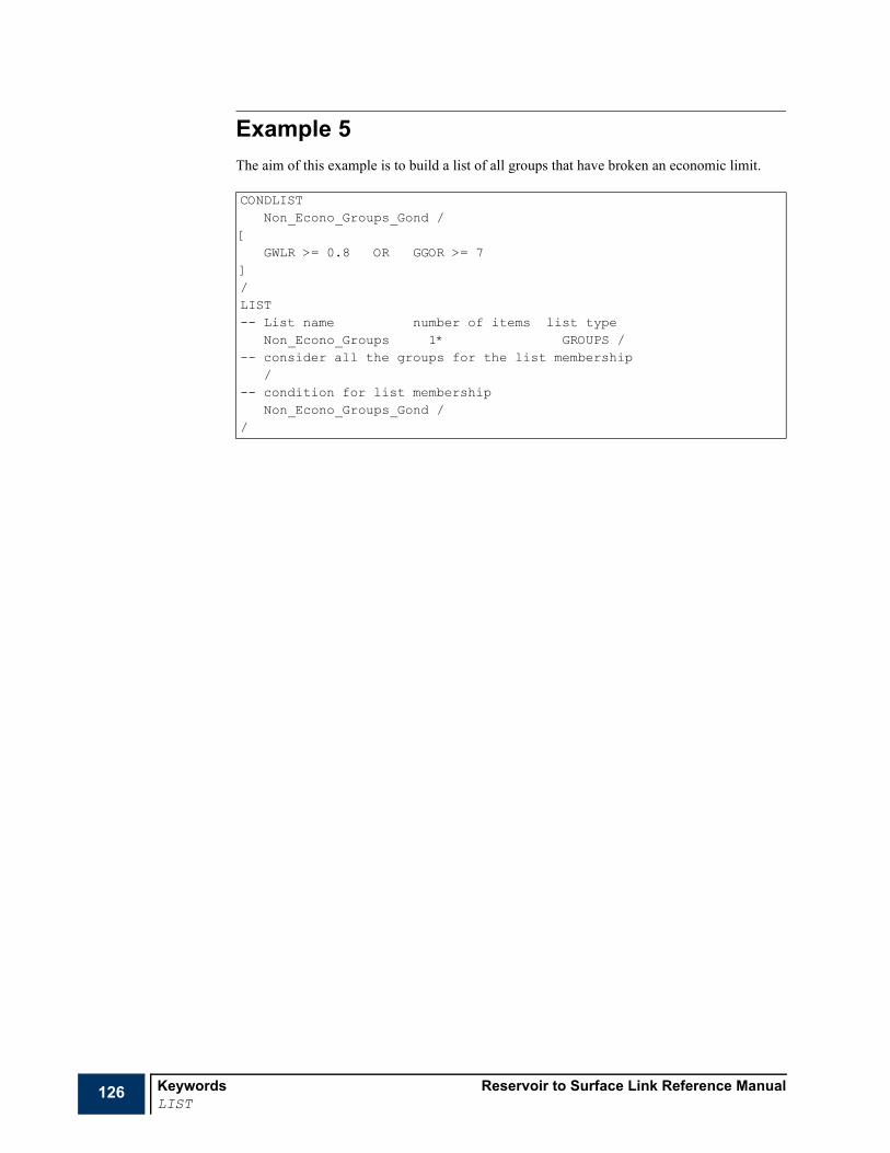
126 Keywords Reservoir to Surface Link Reference ManualLIST
Example 5The aim of this example is to build a list of all groups that have broken an economic limit.
CONDLISTNon_Econo_Groups_Gond /
[GWLR >= 0.8 OR GGOR >= 7
]/LIST-- List name number of items list type
Non_Econo_Groups 1* GROUPS /-- consider all the groups for the list membership
/-- condition for list membership
Non_Econo_Groups_Gond //

Reservoir to Surface Link Reference Manual KeywordsLUTABGEN
127
LUTABGEN Request the generation of Lookup tables for each well in the simulationThe LUTABGEN command turns on lookup table generation. The causes R2SL to generate individual lookup table files for each specified well. These files may be used with the R2SL Lookup Table Module to approximate the full field simulations used to create them.
Each well in the simulation will have a curve file generated for it in the root model directory. The files are name thusly:
where the extension LUT stands for LookUp Table.
To turn on lookup table generation include the LUTABGEN keyword in the RUNSPEC section of the R2SL data file. The keyword consists of two data records.
Record 1
1 This is the type of tables to be generated for each well
• TIME
This option generated tables of simulation time verses well pressure, composition and slope and intercept of well linearized PI at the converged solution point at each timestep.
• CUMULATIVE
This option generated tables of cumulative production or injection verses well pressure, composition and slope and intercept of well linearized PI at the converged solution point at each timestep.
Note The type of the composition, linearized PI and cumulative depends on the preferred operating phase of the well in the reservoir model.
Record 2
2 A list of wells for which tables should be generated. See "Special characters" on page 20 and "Defaulting tasks" on page 21 for details about naming conventions.
• DEFAULT: all wells in the system.
Example
x RUNSPECPROPSSUMMARYSCHEDULE
LUTABGENTIME /PA1 PA3 ‘PB*’‘PC1@RES2’ /
128 Keywords Reservoir to Surface Link Reference ManualMAPBNODS
MAPBNODS Map reservoir or network boundary nodesThis keyword maps reservoir boundary nodes (wells or groups) to their corresponding boundary nodes in the surface network. The keyword is only needed if:
1 there is a surface network present, and
2 the manual mapping option (MANUMAP) has been chosen in RUNMODE item 1.
This is typically the case where some (or all) reservoir boundary nodes have different names than their corresponding surface network boundary nodes.
Note Each surface network boundary node must correspond with either a well or a well group in one of the reservoirs. Only the boundary nodes that do not have the same name as their corresponding well or group need to be listed here. For any network boundary nodes that are not listed here, the controller scans through the coupled ECLIPSE runs to look for a well or a well group with the same name as the network boundary node.
The keyword is followed by any number of records, each terminated with a slash. The set of records should be terminated with a blank record containing just a slash. Each record contains the following items:
1 The network boundary node name
See "Special characters" on page 20 and "Defaulting tasks" on page 21 for details about naming conventions.
Note The asterisk (*) character cannot be used to refer to several nodes in this keyword.
2 The name of the well or well group to which this boundary node corresponds
See "Special characters" on page 20 and "Defaulting tasks" on page 21 for details about naming conventions.
Note The asterisk (*) character cannot be used to refer to several nodes in this keyword.
Note Whether the network boundary nodes map to a well or a well group in a particular reservoir task depends on the entry of the 8th item of TASKSPEC for that task, which may be WELLS, GROUPS or MIXTURE. If the entry is MIXTURE, you must also supply a RESBNODS keyword to specify each boundary node in the reservoir task as either a group or a well.
RUNSPECPROPSSUMMARY
x SCHEDULE

Reservoir to Surface Link Reference Manual KeywordsMAPBNODS
129
ExampleMAPBNODS‘R1W5@NET1’ ‘PROD5@RES1’ /‘R1W6@NET1’ ‘PROD6@RES1’ /‘R2W3@NET1’ ‘PROD6@RES2’ /‘R2W4@NET1’ ‘PROD4@RES2’ //

130 Keywords Reservoir to Surface Link Reference ManualMAXNBALE
MAXNBALE Maximum network balancing error for network boundary nodes at end of time stepThis keyword is used to set an upper limit on the network balancing error at given network boundary nodes that are allowed over a single timestep.
The controller does this by restricting the length of its timestep, based on the previous timesteps network balancing error. The restriction takes place retrospectively, and the timestep is not chopped if a sudden network balancing error causes the limit to be exceeded.
The keyword is followed by any number of records, each terminated with a slash (/). The set of records should be terminated with a blank record containing just a slash. Each record contains the following items:
1 The network boundary node name.
See "Special characters" on page 20 and "Defaulting tasks" on page 21 for details about naming conventions.
Caution When COUPLOCA is used in the RUNSPEC section, the use of “@” to select the task to which the well belong is mandatory in this keyword unless the well name is unique.
2 The maximum value of the node’s network balancing error at the end of the time step
• DEFAULT: infinity
Item 4 of NETBALC can be used to set the network balancing convergence tolerance. At the end of a network balancing process, the percentage relative error (on pressure and dominant flow rate) between the network boundary nodes and their corresponding reservoir boundary nodes is within this tolerance.
Network balancing takes place at:
1 the beginning of the first NUPCOL Newton iteration (set using item 1 of NETBALC) in a tight coupling mode (a single reservoir coupled to surface facility networks),
2 the beginning of the timestep in a loose coupling mode (typically the case of multiple reservoir coupling to surface facility networks).
At the end of the controller’s timestep, the wells’ conditions might deviate significantly from those at the beginning of the time step (a well might die in the worst scenario). This might imply that the network balancing error is not anymore within tolerance.
A minimum length of the controller timestep restricted by network balancing error can be set using MINTSNBE.
Example
x RUNSPECPROPSSUMMARY
x SCHEDULE
MAXNBALE'P*' @NET 10.0 //
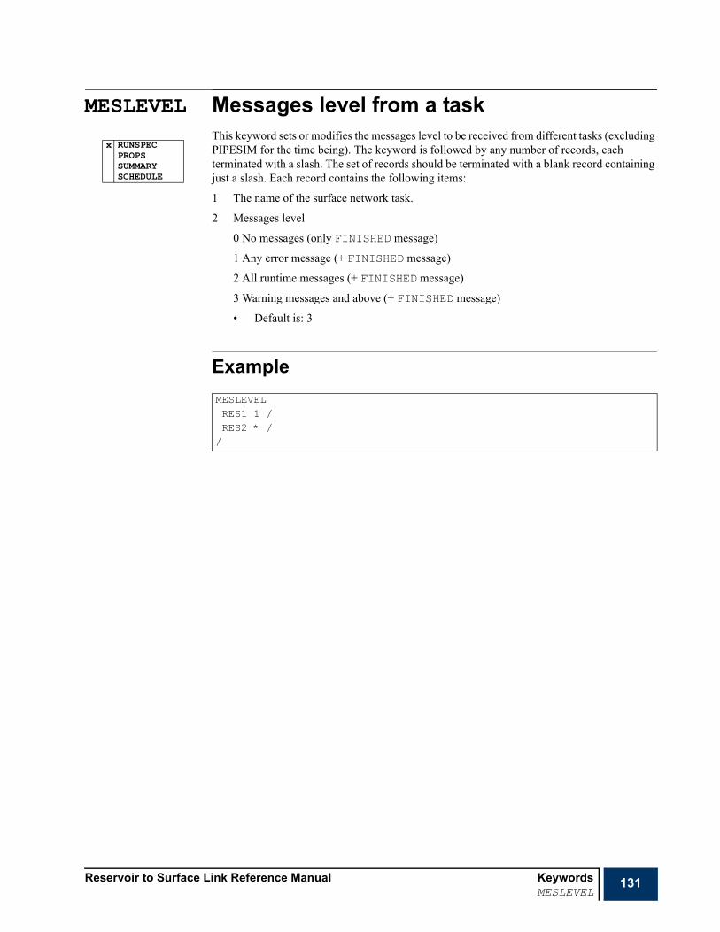
Reservoir to Surface Link Reference Manual KeywordsMESLEVEL
131
MESLEVEL Messages level from a taskThis keyword sets or modifies the messages level to be received from different tasks (excluding PIPESIM for the time being). The keyword is followed by any number of records, each terminated with a slash. The set of records should be terminated with a blank record containing just a slash. Each record contains the following items:
1 The name of the surface network task.
2 Messages level
0 No messages (only FINISHED message)
1 Any error message (+ FINISHED message)
2 All runtime messages (+ FINISHED message)
3 Warning messages and above (+ FINISHED message)
• Default is: 3
Example
x RUNSPECPROPSSUMMARYSCHEDULE
MESLEVELRES1 1 /RES2 * //

132 Keywords Reservoir to Surface Link Reference ManualMESSAGES
MESSAGES Resets message print and stop limitsThis keyword can be used to reset the print and stop limits for messages of any severity type. There are 6 levels of severity:1 = Message (Not an error, purely informative)
2 = Comment (Probably not a data error)
3 = Warning (Possibly a data error)
4 = Problem (Calculation difficulties
5 = Error (Definitely a data error)
6 = Bug (Suspected programming error).
Printing of a particular type of message ceases after its print limit has been reached. The run stops if a particular type of message is generated more times than its stop limit. However, the run is switched into data checking mode if any error message is generated, so that no time step calculations are performed after the next TSTEP or DATES keyword.
The keyword should be followed by up to 12 integers, terminated by a slash (/). Repeat counts (for example 3*1000) and defaults (for example 2*) can be used if required. Any items defaulted or left unspecified will not be altered. The items are initialized with their default values.
1 Print limit for severity 1 messages
• DEFAULT: 1000000
2 Print limit for severity 2 messages
• DEFAULT: 1000000
3 Print limit for severity 3 messages
• DEFAULT: 10000
4 Print limit for severity 4 messages
• DEFAULT: 100
5 Print limit for severity 5 messages
• DEFAULT: 100
6 Print limit for severity 6 messages
• DEFAULT: 100
7 Stop limit for severity 1 messages
• DEFAULT: 1000000
8 Stop limit for severity 2 messages
• DEFAULT: 1000000
9 Stop limit for severity 3 messages
• DEFAULT: 10000
10 Stop limit for severity 4 messages
• DEFAULT: 100
11 Stop limit for severity 5 messages
• DEFAULT: 10
x RUNSPECx PROPSx SUMMARYx SCHEDULE
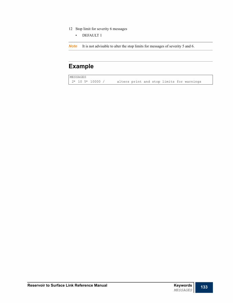
Reservoir to Surface Link Reference Manual KeywordsMESSAGES
133
12 Stop limit for severity 6 messages
• DEFAULT 1
Note It is not advisable to alter the stop limits for messages of severity 5 and 6.
ExampleMESSAGES2* 10 5* 10000 / alters print and stop limits for warnings
134 Keywords Reservoir to Surface Link Reference ManualMFVPDDIM
MFVPDDIM Vapor or liquid mole fraction versus pressure or density table dimensionsThe data consists of up to 3 items, describing the dimensions of the mole fraction versus saturation pressure, pressure or surface oil density tables to be used in the run. The data must be terminated by a slash (/).
Note This keyword cannot be used unless the option COMPOS is employed (item 3 of RUNMODE), an error message is displayed, and the run stops otherwise.
1 Maximum number of mole fraction versus saturation, pressure or surface oil density tables.
The cumulated number of vapor or gas mole fraction versus saturation, pressure or surface oil density tables should be less than this maximum number. The same apply for liquid or oil mole fraction versus saturation pressure, pressure or oil density tables.
• DEFAULT: 1
2 Maximum number of components in each table
• DEFAULT: the actual number of delumped components (super set of components) defined in item 1 of COMPDIMS.
3 Maximum number of rows per table
• DEFAULT: 50
Example
x RUNSPECPROPSSUMMARYSCHEDULE
MFVPDDIM1 10 30 /
Reservoir to Surface Link Reference Manual KeywordsMINTSNBE
135
MINTSNBE Minimum length for controller time step restricted by network balancing errorThis keyword may be used in reservoir simulations coupling to surface facility networks to set a minimum length for timesteps restricted by a boundary node network balancing error at the end of the controller time step.
The network balancing error (for this purpose) is the percentage relative error on the dominant phase flow rate between a network boundary nodes and its corresponding reservoir boundary node (well or well-group).
A large balancing error is sometimes unavoidable during the time step in which a well dies. If any nodes have a maximum tolerable network balancing error at the end of the controller time step (set using MAXNBALE), it is advisable to set a suitable minimum time step size to prevent a large reduction in step size when wells die.
The keyword is followed by a record containing a single number, terminated with a slash (/). The number represents the minimum timestep length that can be imposed a node network balancing error.
• UNITS: days (METRIC), days (FIELD), days (PVT-M).
• DEFAULT: 1 day
Example
RUNSPECPROPSSUMMARY
x SCHEDULE
MINTSNBE5 /

136 Keywords Reservoir to Surface Link Reference ManualMW
MW Molecular weightsIn a FLUID with components, this keyword defines the molecular weight for each component. The keyword should be followed by a record of values terminated with a slash (/).
Note The FLUID number and the number of components corresponding to this FLUID should be previously set using FLUID and NCOMPS, respectively.
Example
RUNSPECx PROPS
SUMMARYSCHEDULE
-- 11 components FLUIDMW28.02 44.01 16.04 30.07 44.09 67.9 110.1 173.1 248.8 361.7 600.9 /
Nc
Nc
Reservoir to Surface Link Reference Manual KeywordsNCOMPS
137
NCOMPS Number of componentsThis keyword sets the number of components, , corresponding to a FLUID. The keyword is followed by a record containing one integer and terminated with a slash (/).
Note The keyword is mandatory to set the number of components corresponding to a given FLUID.
Example
RUNSPECx PROPS
SUMMARYSCHEDULE
NCOMPS11 /
Nc
138 Keywords Reservoir to Surface Link Reference ManualNETBALC
NETBALC Network balancing calculation instructionsThis keyword controls the balancing frequency, the convergence tolerance and iteration limit. The keyword should be followed by a line containing the following data items, ending with a slash (/).
If the record is terminated early, the remaining items assume their default values.
Default values can be specified before the slash by null value indicators (n*, where n is the number of consecutive items to be defaulted). Defaulted items retain their previous values; initial default values are shown below.
1 NUPCOL
The number of Newton iterations at which network balancing takes place.
• DEFAULT: 2 or previous value
Note This is only relevant in the case of a single reservoir simulation. Setting NUPCOL equal 0 implies an explicit coupling; the network is balanced at the beginning of the time step.
2 Network balancing frequency
This sets the frequency at which network balancing takes place in the case of a single reservoir simulation.
0.0 at each simulator time step
>0.0 at the first simulator time step of this controller period.
-1 R2SL will couple at every R2SL and reservoir report step. This ensures all reservoir based keywords between timesteps are properly processed and that any changes associate with time (e.g. opening wells) are captured at the correct time.
-2 only at the specified R2SL report time steps
• DEFAULT: 0.0 or previous value
• UNITS: days (METRIC), days (FIELD), days (PVT-M).
Note This is only relevant in the case of a single reservoir simulation. This option might be used to switch to “loose” coupling in the case of a single reservoir coupled to surface facility networks.
3 Maximum number of iterations allowed in the network balancing calculation
• DEFAULT: 10 or previous value
4 Network balancing convergence tolerance (as percentage error)
The convergence tolerance for network nodal pressures is a factor of 10 smaller than the tolerance set here for the convergence of the network itself.
• DEFAULT: 1.0% or previous value
5 the number of network balancing iterations in which a well can be revived after being closed because it cannot operate against its current THP.
• DEFAULT: MAX (4, item 3 or 2)
RUNSPECPROPSSUMMARY
x SCHEDULE

Reservoir to Surface Link Reference Manual KeywordsNETBALC
139
Note NETBALC can be used as many times as wanted in a controller’s data set to modify any of the above instructions during the coupled run. If NETBALC is used more than once, the default values are set to those defined in a previous NETBALC (aside from item 5, which is always defaulted to MAX (4, item 3).
6 Convergence tolerance for network nodal pressures.
• DEFAULT: 0.1 * the network balancing convergence tolerance set in item 4.
7 Use well linear IPR relationship as boundary condition for network balancing at the first network balancing. This has no effect for the RATE based coupling method where rates are always passed to the network task.
YES Use well linear IPR relationship.
NO Use constant flow rate.
• DEFAULT: YES
Note You are discouraged from using this item as it is meant for debugging purposes.
Note This option can be useful in situations where wells with high PI's are not converging. It only helps in situations where the wells are on BHP control in the reservoir model and are coupled at the bottom hole.
8 Flag indicating whether to set densities or not for a source node in a production network. Densities are queried from the reservoir model(s).
YES Set or update densities when necessary.
NO Do not set densities.
• DEFAULT: YES
Note You are discouraged from using this item as it is meant for debugging purposes.
9 Flag indicating whether to calibrate the black oil model or not for a SOURCE node in a production network. Calibration parameters are queried from the reservoir model(s).
YES Set or update calibration parameters when necessary.
NO Do not set calibration parameters.
• DEFAULT: YES
Note You are discouraged from using this item as it is meant for debugging purposes.
10 Network balancing boundary condition setting parameter.
RATE constant flow rate at all balancing iterations.
PI flow rate versus pressure curves when possible.
FPI fixed PI from well model passed to network - no convergence testing.
FPI9 Nine point averaged fixed PI from well model passed to network - no convergence testing.

140 Keywords Reservoir to Surface Link Reference ManualNETBALC
OBEY Obey limits from the reservoir simulator (ECLIPSE)
• DEFAULT: FPI
Note GAP Model - TH coupling (sources) requires that each coupled source and Injector Well (Gas-lifted, Gas/Water) should have the Injection Fluid separately defined.
Note The FPI option relaxes the network coupling algorithm. PI values are extracted from the reservoir well model and set in the network. The rate solution from the network is then used as the coupling constraint in the reservoir to complete the timestep. There is no iteration between the reservoir and network when this options is selected. It is currently limited to bottom hole coupling.
Note The OBEY method is explicitly designed to allow the reservoir well and group controls to be honoured. R2SL queries rates from the wells at the start of the timestep. These rates are passed to the network solver which calculates a pressure for each coupled well. The reservoir and network pressures are compared. If the reservoir pressure is higher, the well can flow and is left alone. If the reservoir pressure is lower, the wells rate is cutback to converge the pressure.
Note Obey ECLIPSE calculates the cutback based on the pressure difference between reservoir well and the network well. A cutback fraction is calculated for each well (between zero and one) which is applied to the wells coupling constraint target (see keyword COUPLOCA). The only valid coupling constraints are oil rate, water rate, gas rate and liquid rate. If any other coupling constraint is chosen (e.g. bottom hole pressure) the coupling constraint will be switched to the wells dominant phase. The new target for the well is calculated by multiplying the cutback fraction by the coupling constraint.
11 Use non-linear IPR curves as boundary conditions for network balancing. If this item is set to YES, item 8 is ignored.
YES Use non-linear IPR curves.
NO Do not use non-linear IPR curves.
• DEFAULT: NO
Note You are discouraged from using this item as it is meant for debugging purposes.
12 Flag indicating whether using D (Q)/D (THPLIM) instead of using D (Q)/D (THP) (or D (Q)/D (BHPLIM) instead of using D (Q)/D (BHP)) when building an IPR linear curve as boundary conditions for network balancing.
YES D (Q)/D (THPLIM) (or D (Q)/D (BHPLIM)).
NO D (Q)/D (THP) (or D (Q)/D (BHP)).
• DEFAULT: NO
Note You are discouraged from using this item as it is meant for debugging purposes.

Reservoir to Surface Link Reference Manual KeywordsNETBALC
141
13 Flag indicating whether the limit to be set once the network is balanced can be different from BHPLIM (in the case of bottom hole coupling) or THPLIM (in the case of tubing head coupling).
YES Limit can be pressure or rate limit (equal or different to BHPLIM or THPLIM).
NO Limit is BHPLIM (in case of coupling at bottom hole) and THPLIM (in case of coupling at the tubing head).
• DEFAULT: YES
Note You are discouraged from using this item as it is meant for debugging purposes.
14 Flag indicating whether to suspend segmented density head calculation after the first balancing iteration of a network balancing process.
This instructs ECLIPSE to suspend the calculation of the wells’ segregated density heads. ECLIPSE normally performs this calculation once in the first Newton iteration of each time step. However, when performing repeated well calculations within the first Newton iteration (for example while balancing a surface network) the head calculation will be repeated each time. This may have side effects which could, for example, retard the convergence of the network balancing iterations. This flag is used to suspend the segregated density head calculation after the first balancing iteration of each time step.
YES Suspend segmented density head calculation after first balancing iteration.
NO Do not suspend segmented density head calculation after first balancing iteration.
• DEFAULT: YES
Note You are discouraged from using this item as it is meant for debugging purposes.
15 Flag indicating whether to suspend potential rates and guide rate calculation after the first balancing iteration of a network balancing process.
This instructs ECLIPSE to suspend the calculation of the wells’ potential production/injection rates and production/injection guide rates. ECLIPSE 100 normally performs this calculation once in the first Newton iteration of each time step while ECLIPSE 300 performs this calculation once at every NUPCOL Newton iteration. However, when performing repeated well calculations within the first Newton iteration (for example while balancing a surface network) the wells’ potential rate/guide rate calculations will be repeated each time. This may have side effects which could, for example, retard the convergence of the network balancing iterations. This flag is used to suspend the wells’ potential rate/guide rate calculation after the first balancing iteration of each time step.
YES Suspend potential rates and guide rate calculation after first balancing iteration.
NO Do not suspend potential rates and guide rate calculation after first balancing iteration.
• DEFAULT: YES
Note You are discouraged from using this item as it is meant for debugging purposes.
16 Network balancing error is measured in two places in the network-balancing algorithm.
• After solving the well model, a first error is calculated as percentage relative difference between the well flow rates of two successive network balancing iterations. This is escaped at the first network balancing iteration of a network balancing process.
142 Keywords Reservoir to Surface Link Reference ManualNETBALC
• The percentage relative difference between the pressure or flow rates of the reservoir and network boundary nodes. This is performed from the first iteration of the network balancing process.
YES Perform first test.
NO Do not perform first test.
• DEFAULT: YES
Note You are discouraged from using this item as it is meant for debugging purposes.
17 The number of network balancing iterations in which a well can be revived after being closed by the network due to network choking.
• DEFAULT: Item 5 - 1
Note This is should be less than the revival limit for wells shut by the reservoir.
18 If the surface network does not converge, this is classed as a problem. However the user may wish to classify each network solve as a number of problems if this is considered serious enough. This problem count multiplier can be entered here.
• DEFAULT: 10
19 Re-open wells shut-in due to instability during the Obey ECLIPSE balancing algorithm
0 Do not re-open shut-in wells
1 Re-open all wells but only after a certain time has passed (set in item 20 below)
2 Re-open each well but only after a certain time has passed (set in item 20 below) since that well has been been shut-in
• Default: 0
20 Number of days to elapse before a shut-in well will be re-opened
• Default: 0
Examples
Example 1This is a typical setting in both single and multiple reservoir coupling to surface facility networks. It reduces the network balancing tolerance to 1.0% instead of the defaulted value of 0.1%.
NETBALC3* 1.0 /
Reservoir to Surface Link Reference Manual KeywordsNETBALC
143
Example 2This switches the network balancing from “tight” (the defaulted option) to “explicit” in the case of a single reservoir model couples to surface facility networks.
Example 3This switches the network balancing from “tight” (the defaulted option) to “loose” in the case of a single reservoir model couples to surface facility networks. The network is balanced at the beginning of the first time step of each controller 30-days period.
NETBALC1 2* 1.0 /
NETBALC1 30 1* 1.0 /
144 Keywords Reservoir to Surface Link Reference ManualNETBCONF
NETBCONF Modifies the branch configuration of the networkThis keyword may be used to modify the topology of the network by changing the start and end nodes of a branch. An example of the use of this keyword might include switch of a well from a high-pressure manifold to a low-pressure manifold.
The keyword can only be used to modify the condition of an already defined branch. Branches cannot be introduced using this keyword.
The keyword is followed by any number of records each containing up to 3 items and terminated with a slash (/). The set of records should be terminated with a blank record containing just a slash.
1 The network branch name (up to 32 characters).
See "Special characters" on page 20 and "Defaulting tasks" on page 21 for details about naming conventions.
2 Branch start node name (up to 32 characters).
Note The asterisk (*) character cannot be used to refer to several nodes in this keyword.
• DEFAULT: previous value
3 Branch end node name (up to 32 characters).
Note The asterisk (*) character cannot be used to refer to several groups in this keyword.
• DEFAULT: previous value
Caution Care must be taken when selecting the start and end node. They must exist in the same network as the branch. The branch flow direction is decided depending on the start and end node.
Examples
Example 1Consider a well (WELL_1) attached to a low pressure manifold. If the reservoir pressure increases for any reason, it may be necessary to switch to a high pressure manifold (HP_MNFLD). This may be achieved using the following keyword.
RUNSPECPROPSSUMMARY
x SCHEDULE
NETBCONFWELL_1@NETWORK ‘WELL_1_SRC’ ‘HP_MNFLD’ //

Reservoir to Surface Link Reference Manual KeywordsNETBOPEN
145
NETBOPEN Activate or deactivate a network branchThis keyword is used to change the status of a network branch. The keyword should be followed by a set of records. The set of records should be terminated with a blank record containing just a slash.
1 Name of the network branch of the choke inlet (or branch's down tree node in the case of a network task).
See "Special characters" on page 20 and "Defaulting tasks" on page 21 for details about naming conventions.
2 Status
BFORWARD block branch(es) in the forward direction
BREVERSE block branch(es) in the reverse direction
OPEN no blocking branch(es) free to flow in both directions
BLOCK block branch(es) in both direction
• DEFAULT: OPEN
Example
RUNSPECPROPSSUMMARY
x SCHEDULE
NETBOPEN‘*@*’ BFORWARD /
/
146 Keywords Reservoir to Surface Link Reference ManualNETCHOKE
NETCHOKE Modifies the conditions of a physical network chokeThis keyword may be used to modify parameters associated with a physical network choke in the surface network.
The keyword can only be used to modify the condition of an already defined choke. Chokes cannot be introduced using this keyword.
The keyword is followed by any number of records each containing up to 5 items and terminated with a slash (/). The set of records should be terminated with a blank record containing just a slash.
1 Name of the network branch to which the choke belongs.
See "Special characters" on page 20 and "Defaulting tasks" on page 21 for details about naming conventions.
2 Name of the network choke (up to 32 characters).
This item can be defaulted in the case of a network branch with a single choke
3 Is the network choke active?
YES Choke is used in the network balancing calculation.
NO Choke is excluded from the network balancing calculation.
• DEFAULT: NO
4 Type of choke modification operation
SET set the choke diameter to the value in item 5
MULT multiply the choke diameter by the factor in item 5.
The choke multiplier value is expressed as a fraction.
INCR increment the choke diameter by the value in item 5
DECR decrement the choke diameter by the value in item 5
• DEFAULT: SET
Note If the diameter of the choke resulting from a DECR operation is less than or equal to zero, the choke is closed.
5 Value to be set or modified (dependant on item 4).
• UNITS (if applicable), cm (METRIC), inches (FIELD), cm (PVT-M).
• DEFAULT: previous value
This item is ignored if item 3 is set to NO.
Note The physical choke discussed in this section is different from the automatic choke used by the NETLIMIT to set flow rate limits on a network branch. It exists as a user defined entity in the network and has its own physical choke model.
RUNSPECPROPSSUMMARY
x SCHEDULE

Reservoir to Surface Link Reference Manual KeywordsNETCHOKE
147
Examples
Example 1To change the choke diameter of the network choke named CHK_1 of belonging to branch B2 to 3 inches.
Example 2Activates the choke ‘CHK_WELL’ in the branch WELL1 in the network task NET1. Deactivates CHK_WELL in the branch WELL2 in the network task NET1.
NETCHOKEB2 CHK_1 YES 1* 3 //
NETCHOKEWELL1@NET1 CHK_WELL YES /WELL2@NET1 CHK_WELL NO //

148 Keywords Reservoir to Surface Link Reference ManualNETCMPRS
NETCMPRS Modifies the conditions of a network compressorThis keyword may be used to modify parameters associated with a physical network compressor in the surface network.
The keyword can only be used to modify the condition of an already defined compressor. Compressors cannot be introduced using this keyword.
The keyword is followed by any number of records each containing up to 3 items and terminated with a slash (/). The set of records should be terminated with a blank record containing just a slash.
Note Any or all of the parameters specified in items 6 to 9 may be specified. PIPESIM utilizes the limiting factor. At least one of these parameters should be specified.
Note Compressors that utilize a user-defined curve are currently not supported.
1 Name of the network branch to which the compressor belongs.
See "Special characters" on page 20 and "Defaulting tasks" on page 21 for details about naming conventions.
2 Name of the compressor (up to 32 characters).
This item can be defaulted in the case of a network branch with a single compressor.
3 Is the compressor active?
YES Compressor is used in the network balancing calculation.
NO Compressor is excluded from the network balancing calculation
4 Type of compressor modification operation
SET Items 5 to 9 are set to the provided values
MULT Items 5 to 9 are multiplied by the provided values.
INCR Items 5 to 9 are incremented by the provided values.
DECR Items 5 to 9 are decremented by the provided values.
DEFAULT: SET
5 Compressor Efficiency:
• UNITS: Percentage (%)
• DEFAULT: 100%
6 Compressor Power:
• UNITS: kW (METRIC), HP (FIELD), kW (PVT-M)
7 Discharge Pressure:
• UNITS: barsa (METRIC), psia (FIELD), atma (PVT-M).
8 Pressure Differential
• UNITS: bar (METRIC), psi (FIELD), atm (PVT-M).
RUNSPECPROPSSUMMARY
x SCHEDULE
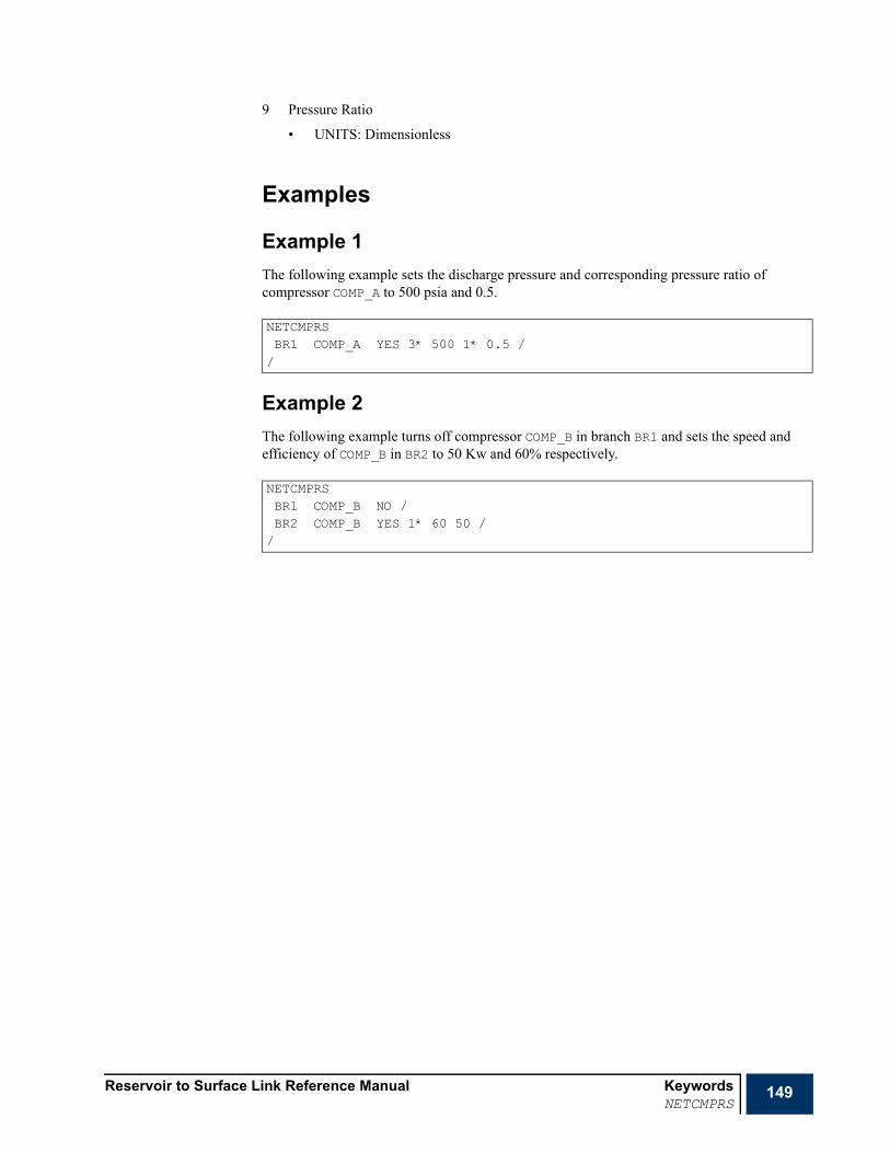
Reservoir to Surface Link Reference Manual KeywordsNETCMPRS
149
9 Pressure Ratio
• UNITS: Dimensionless
Examples
Example 1The following example sets the discharge pressure and corresponding pressure ratio of compressor COMP_A to 500 psia and 0.5.
Example 2The following example turns off compressor COMP_B in branch BR1 and sets the speed and efficiency of COMP_B in BR2 to 50 Kw and 60% respectively.
NETCMPRSBR1 COMP_A YES 3* 500 1* 0.5 //
NETCMPRSBR1 COMP_B NO /BR2 COMP_B YES 1* 60 50 //

150 Keywords Reservoir to Surface Link Reference ManualNETDEBUG
NETDEBUG Set network debugging level for a network taskThis keyword is used to set the debugging level for a network task (PIPESIM for the moment). The keyword is followed by any number of records, each terminated with a slash. The set of records should be terminated with a blank record containing just a slash. Each record contains the following items:
1 The name of the surface network task.
Up to six integers (2 to 7) selecting the debugging information needed.
1 if debugging information needed
0 if debugging information is not needed
• Default is: 0 for each of these items
2 Messages
This is the lowest level of debug. General operation messages are written to the SLAVE.DBG file (for example, set commands in TNT card format).
3 Problems
Possible problems with the run are outputted to the SLAVE.DBG file (such as an unrecognized source name resulting in an invalid set command).
4 Detailed trace
Full detailed trace information is written to the SLAVE.DBG file. It includes detailed composition information (for example component liquid and vapor mole fractions).
5 Set batch files
Prepares set batch files for the PIPESIM SLAVE interactive mode.
6 Query batch files
Prepares query batch files for the PIPESIM SLAVE interactive mode.
7 Bugs
Report a possible bug.
8 Full PIPESIM internal Debug
Turns on full PIPESIM internal debug to facilitate developer fault finding.
Example
RUNSPECPROPSSUMMARY
x SCHEDULE
NETDEBUGNET1 0 1 1 0 0 1 /NET2 6*0 //

Reservoir to Surface Link Reference Manual KeywordsNETGLIFT
151
NETGLIFT Modifies gas lift conditions on a network branchThis keyword may be used to modify parameters associated with gas lift in the surface network.
The keyword can only be used to modify the condition of already defined gas lift points. Gas lift points cannot be introduced using this keyword.
The keyword is followed by any number of records each containing up to 3 items and terminated with a slash (/). The set of records should be terminated with a blank record containing just a slash.
1 Name of the network branch in which gas is injected.
See "Special characters" on page 20 and "Defaulting tasks" on page 21 for details about naming conventions.
2 Name of the gas lift point (up to 32 characters).
This item can be defaulted in the case of a network branch with a single lift point.
3 Type of gas lift point modification operation
SET Item 4 is set to the provided value.
MULT Items 4 is multiplied by the provided value.
INCR Items 4 is incremented by the provided value.
DECR Items 4 is decremented by the provided value.
• DEFAULT: SET
4 Injected gas rate (dependant on item 3).
• Units (if applicable): sm3/day (METRIC), Mscf/day (FIELD), sm3/day (PVT-M).
5 Gas density
• UNITS: kg/sm3 (METRIC), lb/Mscf (FIELD), kg/sm3 (PVT-M)
• DEFAULT: the value set in the network model.
6 Gas temperature
• Units: oC (METRIC), oF (FIELD), oC (PVT-M).
• DEFAULT: the value set in the network model.
7 Gas density type
1 Density units - with units as per item 5 above.
2 Specific gravity relative to air.
• DEFAULT: 1
Note When PIPESIM Net is used to simulate gaslift, the NETGLIFT is limited to operating on simple gas lift points. The gas lift values must be defined in the PIPESIM Net branch files using the INJGAS keyword. Detailed modeling using INJPORT is not permitted in this version.
RUNSPECPROPSSUMMARY
x SCHEDULE

152 Keywords Reservoir to Surface Link Reference ManualNETGLIFT
ExampleThis increases the lift gas injected at point LIFTPT1 in branch BR1 by 10%.
NETGLIFTBR1 LIFTPT1MULT 1.1 /
/
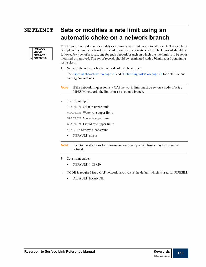
Reservoir to Surface Link Reference Manual KeywordsNETLIMIT
153
NETLIMIT Sets or modifies a rate limit using an automatic choke on a network branchThis keyword is used to set or modify or remove a rate limit on a network branch. The rate limit is implemented in the network by the addition of an automatic choke. The keyword should be followed by a set of records, one for each network branch on which the rate limit is to be set or modified or removed. The set of records should be terminated with a blank record containing just a slash.
1 Name of the network branch or node of the choke inlet.
See "Special characters" on page 20 and "Defaulting tasks" on page 21 for details about naming conventions
Note If the network in question is a GAP network, limit must be set on a node. If it is a PIPESIM network, the limit must be set on a branch.
2 Constraint type:
ORATLIM Oil rate upper limit.
WRATLIM Water rate upper limit
GRATLIM Gas rate upper limit
LRATLIM Liquid rate upper limit
NONE To remove a constraint
• DEFAULT: NONE
Note See GAP restrictions for information on exactly which limits may be set in the network.
3 Constraint value.
• DEFAULT: 1.0E+20
4 NODE is required for a GAP network. BRANCH is the default which is used for PIPESIM.
• DEFAULT: BRANCH.
RUNSPECPROPSSUMMARY
x SCHEDULE

154 Keywords Reservoir to Surface Link Reference ManualNETLIMIT
Figure 5.1 The implementation of an automatic choke on a network branch
Note To apply an automatic choke on a network branch (branch LINE_EXPORT for example in Figure 5.1, A), you should account for that when building the network by adding a branch for the purpose (branch GATHER _CHK in Figure 5.1 B). The branch should be horizontal with zero elevation difference, roughness, and rate of undulation. For that purpose, the branch should be horizontal and have zero roughness.

Reservoir to Surface Link Reference Manual KeywordsNETLIMIT
155
Example
Example 1To apply an upper limit of 30,000 on oil production, a choke is defined on the network branch GATHER_CHK (case of PIPESIM).
NETLIMITGATHER_CHK ORATLIM 30000 //

156 Keywords Reservoir to Surface Link Reference ManualNETPUMP
NETPUMP Modifies the conditions of a network pumpThis keyword may be used to modify parameters associated with a pump in the surface network.
The keyword can only be used to modify the condition of an already defined pump. Pumps can not be introduced using this keyword.
The keyword is followed by any number of records each containing up to 10 items and terminated with a slash (/). The set of records should be terminated with a blank record containing just a slash.
Note Any or all of the parameters specified in items 5 to 9 may be specified. PIPESIM utilizes the limiting factor. At least one of theses parameter should be specified.
Note Compressors that utilize a user defined curve are current not supported.
1 Name of the network branch to which the pump belongs.
See "Special characters" on page 20 and "Defaulting tasks" on page 21 for details about naming conventions.
2 Name of the pump (up to 32 characters).
This item can be defaulted in the case of a network branch with a single pump.
3 Is the pump active?
YES Pump are used in the network balancing calculation.
NO Pump are excluded from the network balancing calculation.
4 Type of pump modification operation
SET Items 5 to 9 are set to the provided values.
MULT Items 5 to 9 are multiplied by the provided values.
INCR Items 5 to 9 are incremented by the provided values.
DECR Items 5 to 9 are decremented by the provided values.
DEFAULT: SET
5 Pump Efficiency:
• UNITS: Percentage (%)
• DEFAULT: 100%
6 Pump Power:
• UNITS: kW (METRIC), HP (FIELD), kW (PVT-M).
7 Discharge Pressure:
• UNITS: barsa (METRIC), psia (FIELD), atma (PVT-M).
8 Pressure Differential
• UNITS: bar (METRIC), psi (FIELD), atm (PVT-M).
9 Pressure Ratio
• UNITS: Dimensionless
RUNSPECPROPSSUMMARY
x SCHEDULE

Reservoir to Surface Link Reference Manual KeywordsNETPUMP
157
ExampleThis sets the discharge pressure and corresponding pressure ratio of pump PUMP_A to 500 psia and 0.5.
NETPUMPBR1 PUMP_A YES 3* 500 1* 0.5 //

158 Keywords Reservoir to Surface Link Reference ManualNETTYPE
NETTYPE Specify network typeThis keyword is used to define the type of the network defined with keyword TASKSPEC. The keyword is followed by any number of records, each terminated with a slash. The set of records should be terminated with a blank record containing just a slash. Each record contains the following items:
1 The name of the surface network task.
2 Network type:
BOPROD production, black oil
WINJ water injection
BOGINJ gas injection, black oil
BOPROINJ mixed production injection system, black oil
COPROD production, compositional
COGINJ gas injection, compositional
• Default is: automatically selected (if possible)
Note In the case of more than one network model in the same coupled run, the network models should be in different directories to avoid filename conflicts.
Note The BOPROINJ options allows mixed production and injection black oil networks to be specified.
Example
x RUNSPECPROPSSUMMARYSCHEDULE
NETTYPENET1 COPROD //

Reservoir to Surface Link Reference Manual KeywordsNINJGAS
159
NINJGAS Specifies the nature of the injected gas in a network nodeThis keyword is used to specify the nature of the gas injected at a terminal node in an injection network. The keyword is followed by any number of records each containing up to 5 items and terminated with a slash (/). The set of records should be terminated with a blank record containing just a slash.
This keyword requires the existence of a compositional production network and a compositional gas injection network in the coupled run.
Note This keyword cannot be used unless the option COMPOS is employed in RUNMODE (item 3), an error message is displayed, and the run stops otherwise.
1 Node name
See "Special characters" on page 20 and "Defaulting tasks" on page 21 for details about naming conventions.
Note The asterisk (*) character cannot be used to refer to several nodes in this keyword.
2 Nature of injected gas
STREAM The molar composition of the injected fluid has been defined using the WELLSTRE keyword. The name of the stream must be entered in item 3.
NV The injected fluid is to be taken from the vapor production of a nominated node (from a production network). The name of the node must be entered in item 3.
3 Vapor source.
Required if item 2 is STREAM or NV
Note The asterisk (*) character cannot be used to refer to several nodes in this keyword.
4 The stage of the separator that defines the fluid composition for injection
• DEFAULT: 0, use vapor from the whole separator as injection fluid
5 In case item 2 is NV, a flag indicating whether or not to limit the amount of vapor injected in the network node (defined in item 1) to that produced from the node in item 3 (from the appropriate stage of separator). In the case the node has already an upper limit injection rate, the minimum between these two constraints will be chosen.
NO No limit on the gas injection amount
YES The injected gas amount is limited by the produced vapor from the given separator stage set in item 4
DEFAULT: NO
RUNSPECPROPSSUMMARY
x SCHEDULE

160 Keywords Reservoir to Surface Link Reference ManualNINJGAS
Note This keyword does not set the separator details at the production node from which gas is taken. You should do this by associating a separator to the appropriate node using SETSEP. The use of this keyword might only be needed in the case of more than one separator to switch from the defaulted separator.
Caution Gas re-injection in an injection network from a production network’s node is restricted for the time being to the terminal node of the production network. Otherwise, the gas quantity taken from the production network’s node is not accounted for when calculating the pressure drop in the network. In other words, the pressure drop in the network in this case corresponds to the maximum flow rate in the network when gas re-injection does not exist.
ExampleThe composition of the vapor produced from the last stage of the associated separator at the production network node EXPORT belonging to task NET_PROD is set as the composition of the injected gas in the terminal node TERMINAL of the compositional gas injection network NET_GINJ. The amount of gas injected in TERMINAL is limited to that resulting last stage of the separator at EXPORT.
NINJGASTERMINAL@NET_GINJ NV EXPORT@NET_PROD 1* YES //

Reservoir to Surface Link Reference Manual KeywordsNOECHO
161
NOECHO Disable echoing of the input fileThe keyword causes the echo of the data input that is produced at the start of each run to be switched off from the next keyword until a subsequent ECHO keyword is encountered (or until the end of the data).
NOECHO may be used to reduce the amount of print-out from a run, or to avoid the output of large included files.
ECHO and NOECHO may be specified in any section, and any number of times in an input file.
The NOECHO keyword has no associated data.
x RUNSPECx PROPSx SUMMARYx SCHEDULE

162 Keywords Reservoir to Surface Link Reference ManualNSINKBO
NSINKBO Sets or modifies sink node conditions in a black oil networkThis keyword sets or modifies the conditions at a sink node belonging to a black oil network. The keyword can be used for two purposes:
1 setting or modifying conditions at a sink node belonging to an injection network; sink node in this case should not map to any reservoir boundary node
2 modifying conditions of a terminal node in a production network.
The keyword is followed by any number of records each containing up to 7 items and terminated with a slash (/). The set of records should be terminated with a blank record containing just a slash.
Note Restrictions apply on the use of this keyword in the current release (see "NSINKBO" on page 336)
1 Node name or node name root
See "Special characters" on page 20 and "Defaulting tasks" on page 21 for details about naming conventions.
2 Injected phase
WATER
GAS
• DEFAULT: WATER
Note This item should be defaulted when modifying conditions of a terminal node in a production network.
3 Sink type:
RATE defined rate.
This requires the rate of the phase in item 2 to be defined as well as the rate in item 4.
PRES defined pressure.
This requires the pressure to be supplied in item 5.
II defined injectivity index
This requires the linearized well core’s slope (item 6) and intercept (item 7) defining injected phase rate versus pressure to be supplied.
• DEFAULT: PRES
Note GAP injection wells cannot be rate specified and so must be specified using an INJECTIVITY INDEX. GAP sinks may be RATE specified. GAP production manifolds may be PRESSURE specified
RUNSPECPROPSSUMMARY
x SCHEDULE

Reservoir to Surface Link Reference Manual KeywordsNSINKBO
163
4 Rate of the injected phase
• UNITS: sm3/day (METRIC), stb/day for oil or water (FIELD), Mscf/day for gas (FIELD), sm3/days (PVT-M)
• DEFAULT: 0.0
Note This item should be defaulted when modifying conditions of a terminal node in a production network.
5 Pressure
• UNITS: barsa (METRIC), psia (FIELD), atma (PVT-M),
• DEFAULT: 14.7 psia=1.013 barsa.
6 Slope of the linearized well curve.
7 Intercept of the linearized well curve.
ExampleNSINKBOSINK GAS PRES 1* 500 //

164 Keywords Reservoir to Surface Link Reference ManualNSINKCO
NSINKCO Sets or modifies sink node conditions in a compositional gas injection networkThis keyword sets or modifies the conditions at a sink node belonging to a compositional gas injection or production network. The keyword can be used for two purposes:
• setting or modifying conditions at a sink node belonging to an injection network; sink node in this case should not map to any reservoir boundary node
• modifying conditions of a terminal node in a production network.
The keyword is followed by any number of records each containing up to 6 items and terminated with a slash (/). The set of records should be terminated with a blank record containing just a slash.
Note Restrictions apply on the use of this keyword in the current release (see "NSINKCO" on page 336).
Note Not applicable for GAP networks.
1 Node name or node name root
See "Special characters" on page 20 and "Defaulting tasks" on page 21 for details about naming conventions.
2 Sink type:
RATE defined rate.
This requires the total mass rate (item 3) to be defined
PRES defined pressure
This requires the pressure (item 4) to be supplied.
II defined injectivity index
This requires the linearized well core’s slope (item 5) and intercept (item 6) defining injected phase rate versus pressure to be supplied.
• DEFAULT: PRES
3 Total mass rate
• UNITS: kg/day (METRIC), lb/day (FIELD), kg/day (PVT-M)
• DEFAULT: 0.0
Note This item should be defaulted when modifying conditions of a terminal node in a production network.
4 Pressure
• UNITS: barsa (METRIC), psia (FIELD), atma (PVT-M)
• DEFAULT: 14.7 psia=1.013 barsa.
5 Slope of the linearized well curve.
6 Intercept of the linearized well curve.
RUNSPECPROPSSUMMARY
x SCHEDULE

Reservoir to Surface Link Reference Manual KeywordsNSINKCO
165
ExampleNSINKCOSINK PRES 1* 500 //
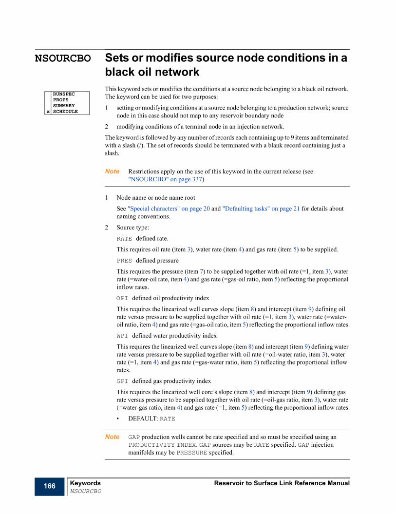
166 Keywords Reservoir to Surface Link Reference ManualNSOURCBO
NSOURCBO Sets or modifies source node conditions in a black oil networkThis keyword sets or modifies the conditions at a source node belonging to a black oil network. The keyword can be used for two purposes:
1 setting or modifying conditions at a source node belonging to a production network; source node in this case should not map to any reservoir boundary node
2 modifying conditions of a terminal node in an injection network.
The keyword is followed by any number of records each containing up to 9 items and terminated with a slash (/). The set of records should be terminated with a blank record containing just a slash.
Note Restrictions apply on the use of this keyword in the current release (see "NSOURCBO" on page 337)
1 Node name or node name root
See "Special characters" on page 20 and "Defaulting tasks" on page 21 for details about naming conventions.
2 Source type:
RATE defined rate.
This requires oil rate (item 3), water rate (item 4) and gas rate (item 5) to be supplied.
PRES defined pressure
This requires the pressure (item 7) to be supplied together with oil rate (=1, item 3), water rate (=water-oil rate, item 4) and gas rate (=gas-oil ratio, item 5) reflecting the proportional inflow rates.
OPI defined oil productivity index
This requires the linearized well curves slope (item 8) and intercept (item 9) defining oil rate versus pressure to be supplied together with oil rate (=1, item 3), water rate (=water-oil ratio, item 4) and gas rate (=gas-oil ratio, item 5) reflecting the proportional inflow rates.
WPI defined water productivity index
This requires the linearized well curves slope (item 8) and intercept (item 9) defining water rate versus pressure to be supplied together with oil rate (=oil-water ratio, item 3), water rate (=1, item 4) and gas rate (=gas-water ratio, item 5) reflecting the proportional inflow rates.
GPI defined gas productivity index
This requires the linearized well core’s slope (item 8) and intercept (item 9) defining gas rate versus pressure to be supplied together with oil rate (=oil-gas ratio, item 3), water rate (=water-gas ratio, item 4) and gas rate (=1, item 5) reflecting the proportional inflow rates.
• DEFAULT: RATE
Note GAP production wells cannot be rate specified and so must be specified using an PRODUCTIVITY INDEX. GAP sources may be RATE specified. GAP injection manifolds may be PRESSURE specified.
RUNSPECPROPSSUMMARY
x SCHEDULE
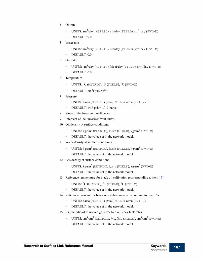
Reservoir to Surface Link Reference Manual KeywordsNSOURCBO
167
3 Oil rate
• UNITS: sm3/day (METRIC), stb/day (FIELD), sm3/day (PVT-M)
• DEFAULT: 0.0
4 Water rate
• UNITS: sm3/day (METRIC), stb/day (FIELD), sm3/day (PVT-M)
• DEFAULT: 0.0
5 Gas rate
• UNITS: sm3/day (METRIC), Mscf/day (FIELD), sm3/day (PVT-M)
• DEFAULT: 0.0
6 Temperature
• UNITS: oC (METRIC), oF (FIELD), oC (PVT-M)
• DEFAULT: 60 oF=15.56oC.
7 Pressure
• UNITS: barsa (METRIC), psia (FIELD), atma (PVT-M)
• DEFAULT: 14.7 psia=1.013 barsa.
8 Slope of the linearized well curve.
9 Intercept of the linearized well curve.
10 Oil density at surface conditions.
• UNITS: kg/sm3 (METRIC), lb/stb (FIELD), kg/sm3 (PVT-M)
• DEFAULT: the value set in the network model.
11 Water density at surface conditions.
• UNITS: kg/sm3 (METRIC), lb/stb (FIELD), kg/sm3 (PVT-M)
• DEFAULT: the value set in the network model.
12 Gas density at surface conditions.
• UNITS: kg/sm3 (METRIC), lb/stb (FIELD), kg/sm3 (PVT-M)
• DEFAULT: the value set in the network model.
13 Reference temperature for black oil calibration (corresponding to item 15).
• UNITS: oC (METRIC), oF (FIELD), oC (PVT-M)
• DEFAULT: the value set in the network model.
14 Reference pressure for black oil calibration (corresponding to item 15).
• UNITS: barsa (METRIC), psia (FIELD), atma (PVT-M)
• DEFAULT: the value set in the network model.
15 Rs, the ratio of dissolved gas over free oil stock tank rates.
• UNITS: sm3/sm3 (METRIC), Mscf/stb (FIELD), sm3/sm3 (PVT-M)
• DEFAULT: the value set in the network model.
168 Keywords Reservoir to Surface Link Reference ManualNSOURCBO
Note Items 3, to 6, and 8 to 15 are ignored when setting conditions at a constant pressure terminal node in an injection network.
Note Items 13, 14, and 15 are used for black oil correlation calibration in the network model.
ExampleNSOURCBOSOURCE_1 RATE 1000.0 0.0 1500.0 //

Reservoir to Surface Link Reference Manual KeywordsNSOURCCO
169
NSOURCCO Sets or modifies source node conditions in a compositional networkThis keyword sets or modifies the conditions at a source node belonging to a compositional network model. The keyword can be used for two purposes:
1 setting or modifying conditions at a source node belonging to a production network; source node in this case should not map to any reservoir boundary node
2 modifying conditions of a terminal node in an injection network.
The keyword is followed by any number of records each containing up to 8+Nc items (where Nc is the number of components) and terminated with a slash (/). The set of records should be terminated with a blank record containing just a slash.
Note Restrictions apply on the use of this keyword in the current release (see "NSOURCCO" on page 337).
Note Not applicable for GAP networks.
1 Node name or node name root
See "Special characters" on page 20 and "Defaulting tasks" on page 21 for details about naming conventions.
2 Source type:
RATE defined rate.
This requires the total mass rate (item 3) and components mass fraction (items 9 and up) as well as water mass rate (item 4) to be supplied.
PRES defined pressure
This requires the pressure to be supplied, together with the total mass rate (=1, item 3); components mass fraction (items 9 and up), and the water mass rate (water mass rate / total mass rate, item 4) reflecting the proportional inflow rates.
PI defined total mass rate productivity index
This requires the linearized well curves slope (item 7) and intercept (item 8) defining total mass rate versus pressure to be supplied, together with the total mass rate (=1, item 3), components mass fraction (items 9 and u), and the water mass rate (water mass rate / total mass rate, item 4) reflecting the proportional inflow rates.
• DEFAULT: RATE
3 Total hydrocarbon mass rate
• UNITS: kg/day (METRIC), lb/day (FIELD), kg /day (PVT-M)
• DEFAULT: 0.0
4 Water mass rate
• UNITS: kg/day (METRIC), lb/day (FIELD), kg/day (PVT-M)
• DEFAULT: 0.0
RUNSPECPROPSSUMMARY
x SCHEDULE
170 Keywords Reservoir to Surface Link Reference ManualNSOURCCO
5 Temperature
• UNITS: oC (METRIC), oF (FIELD), oC (PVT-M)
• DEFAULT: 60 oF=15.56oC.
6 Pressure
• UNITS: barsa (METRIC), psia (FIELD), atma (PVT-M)
• DEFAULT: 14.7 psia=1.013 barsa.
7 Slope of the linearized well curve.
8 Intercept of the linearized well curve.
9 Components mass fraction (up to the number of components). The number of components is the same as the network task to which belong the node defined in item 1.
ExampleNSOURCCOSOURCE_1 RATE 1.0E+4 0.0 4* 1.0 //
Reservoir to Surface Link Reference Manual KeywordsOBEYECL
171
OBEYECL Changes the network balancing setting for the OBEY ECLIPSE coupling method.This keyword sets of modifies the OBEYECL network balancing settings for individual wells:
• The keyword must be used in conjunction with the OBEYECL coupling mode. This option is selected by setting item 10 of NETBALC to OBEY.
The keyword is followed by any number of records each containing up to 8 items and terminated with a slash (/). The set of records should be terminated with a blank record containing just a slash.
Note This keyword should only be used in conjunction with the OBEYECLIPSE network coupling method.
1 Well name or node name root
See "Special characters" on page 20 and "Defaulting tasks" on page 21 for details about naming conventions.
2 Well shut in action.
The action the coupling algorithm will take when a well is cutback below its cutback limit.:
SHUT The well will be shut in
IGNORE The well be excluded from the cutback process
• DEFAULT: SHUT
3 Maximum number of cutbacks that may be performed
The maximum number of times a well can be cut back within a timestep
4 Minimum limit on cutback for oil rate
• UNITS: sm3/day (METRIC), stb/day (FIELD), sm3/day (PVT-M)
• DEFAULT: 0.0
5 Minimum limit on cutback for water rate
• UNITS: sm3/day (METRIC), stb/day (FIELD), sm3/day (PVT-M)
• DEFAULT: 0.0
6 Minimum limit on cutback for gas rate
• UNITS: sm3/day (METRIC), Mscf/day (FIELD), sm3/day (PVT-M)
• DEFAULT: 0.0
7 Minimum limit on cutback for liquid rate
• UNITS: sm3/day (METRIC), stb/day (FIELD), sm3/day (PVT-M)
• DEFAULT: 0.0
8 This is no longer in use.
RUNSPECPROPSSUMMARY
x SCHEDULE

172 Keywords Reservoir to Surface Link Reference ManualOBEYECL
9 Limit on relaxation parameter
Wells are cut back or opened up according to a calculated ratio and represents the calculated flow rate divided by the flow rate from the last iteration. This ratio can be limited to contain unstable well behavior. This limit must be between 0 and 1. If the well is to be cut back, the minimum cut back ratio will be the limit specified. If the well is to be opened up, the maximum open up ratio will be the inverse of this number.
• Default: 0.5
Example
OBEYECLWELL2 SHUT 10 4*10.0 0.9 //
Reservoir to Surface Link Reference Manual KeywordsOMEGAA
173
OMEGAA Overrides default Ωa values In a FLUID with components, this keyword defines the Ωa values or each component. The keyword should be followed by a record of values terminated with a slash (/).
Note The FLUID number and the number of components corresponding to this FLUID should be previously set using FLUID and NCOMPS, respectively.
Example
RUNSPECx PROPS
SUMMARYSCHEDULE
-- 11 components FLUIDOMEGAA11*0.086640350 /
Nc
Nc
174 Keywords Reservoir to Surface Link Reference ManualOMEGAB
OMEGAB Overrides default Ωb values In a FLUID with components, this keyword defines the Ωb values or each component. The keyword should be followed by a record of values terminated with a slash (/).
Note The FLUID number and the number of components corresponding to this FLUID should be previously set using FLUID and NCOMPS, respectively.
Example
RUNSPECx PROPS
SUMMARYSCHEDULE
-- 11 components FLUIDOMEGAB11*0.42748020 /
Nc
Nc

Reservoir to Surface Link Reference Manual KeywordsOMFVD
175
OMFVD Stock tank oil mole fraction with respect to surface oil density table The data comprises a table of stock tank oil mole fraction with respect to surface oil density data. Each table consists of columns of data, and is terminated with a slash (/).
Column:
1 Surface oil density values.
The values should increase monotonically down the column.
• UNITS: kg/m3 (METRIC), lb/ft3 (FIELD), kg/m3 (PVT-M)
2 to
The corresponding values of , the stock tank oil mole fractions. The mole fractions specified must add up to unity, and the program checks that this is the case.
The maximum number of OMVFD tables as well as the maximum number of rows in a table are set using MFVPDDIM. The number of components should be previously set using NCOMPS.
Note The FLUID number and the number of components corresponding to this FLUID should be previously set using FLUID and NCOMPS, respectively.
Example
RUNSPECx PROPS
SUMMARYSCHEDULE
OMFVD.../
Nc 1+
Nc 1+
xi Nc
176 Keywords Reservoir to Surface Link Reference ManualOPTIONSM
OPTIONSM Activates special program options
This keyword can be used to activate special options in R2SL.
Caution For developer debugging purpose only.
The keyword should be followed by one record containing up to 1 item and terminated with a slash (/). Each of these items activates a special option. A value of zero switches off the option while a value other than zero activates it. If fewer than2 integers are read, the remainder are left unchanged. Note that repeat counts (for example 3*0) can be used if required (there must be no spaces before or after the asterisk).
1 Set to 0 for the coupled run to stop after one of the reservoir models stops due to reaching the END keyword (or because all wells get shut or stopped for any reason).
2 Set to 1 if message passing using PVM instead of MPI.
3 Set to 1 if restart files not to be used in a network balancing process (for solving the PIPESIM network model).
4 By default, R2SL blocks reverse flow on all “boundary” and “terminal” branches. Setting this option to 1, prohibits R2SL from doing so.
5 Set to 1 to disable extrapolation in table lookup during black oil delumping.
6 Set to 1 to relax restrictions on higher level group control.
7 Set to 1 to turn off the ability to choke the network back at subordinate group or well level to honour a higher level group control limit imposed using the GCONEXTN keyword.
8 Set to 1 to prevent flow rate specified boundary conditions in the network.
9 Set to 1 to force Field Events to do a full reservoir surface balance when required instead of a resolve of the network (slower but more accurate).
10 Set to 1 to turn off the SQP optimizer in GAP.
11 Set to 1 to prevent the check for flow-specified boundary nodes subordinate to the chosen node or branch in NETLIMIT. This is useful in the case that the Network has multiple terminal nodes as a tree structure
12 Set to 1 to prevent the preferred phase of the PI passed to the network being changed from the value set by the reservoir.
13 Set to 1 to enable revival of wells that have been shut by the network solver. For example, if the GAP optimizer persistently shuts a well during a timestep, the well will be revived in the following timestep.
14 Set to 1 to enable an option to turn on wells at the start of the network balancing process that have died in the reservoir due to a physical reason during the preceding timestep. The pressure limit is reset to its original value to give the well a better chancing of flowing.
15 Set to 1 to enable completion level functionality. This includes reporting, field events and black oil delumping. Black oil delumping at the well level takes place by default.
16 Deprecated.
17 Set to 1 to ensure that the linearized IPR curves queried from the well model in the reservoir are always used as the boundary condition to the network.
18 Do not allow rate based specifications in GAP. This defaults to true.
x RUNSPECPROPSSUMMARYSCHEDULE
Reservoir to Surface Link Reference Manual KeywordsOPTIONSM
177
19 Use NGL Tables.
20 Use PI scaling for network balancing.
21 Deprecated.
22 Use gradient based PI.
23 Turn on KZP debugging.
24 Set to 1 to enable well segment level functionality.
25 Set to 1 to use Wells Offline mode in the network model. In this mode, curves are created for the wells in the network model, and is meant primarily for BH coupling. This has the effect of:
• Increasing the stability of the coupling algorithms by smoothing out discontinuities in the multiphase flow model, and handling wells operating close to their unstable region.
• Enabling a substantial speedup of the network model.
26 Force automatic mapping of nodes and wells with the same name even if manual mapping has been selected.
27 Enable time stepping on field events: will take into account the next field event when determining internal time step size.
28 Deprecated.
29 Set to 1 to suppress network balancing after every WHEN event.
30 Set to 1 to enable SPIN communication between R2SL and ECLIPSE, which could speed up the simulation in large Reservoir Coupling runs.
31 Set to 1 to synchronize reservoir models at the IAM report step only. Each ECLIPSE model will solve according to its own schedule section, up to each IAM report step, where R2SL will execute.
ExampleOPTIONSM4* 1 /

178 Keywords Reservoir to Surface Link Reference ManualPCRIT
PCRIT Critical pressuresIn a FLUID with components, this keyword defines the critical pressure for each component. The keyword should be followed by a record of values terminated with a slash (/).
• UNITS: barsa (METRIC), psia (FIELD), atma (PVT-M)
Note The FLUID number and the number of components corresponding to this FLUID should be previously set using FLUID and NCOMPS, respectively.
Example
RUNSPECx PROPS
SUMMARYSCHEDULE
-- 11 components FLUIDPCRIT492 1071 667 708 615 514 410 247 218 174 138 /
Nc
Nc

Reservoir to Surface Link Reference Manual KeywordsPRCORR
179
PRCORR Request modified Peng-Robinson EoSThis keyword requests that a slightly modified form of the Peng-Robinson equation of state is to be used. This changes the usual form of the value as a function of the component acentric factor.
The keyword has no arguments, and has no effect on equations of state other than the Peng-Robinson.
Note The FLUID number should be previously set using FLUID.
RUNSPECx PROPS
SUMMARYSCHEDULE
Ωa

180 Keywords Reservoir to Surface Link Reference ManualRCMASTS
RCMASTS Minimum length for controller time step restricted by flow changeThis keyword may be used in a Reservoir Coupling run to set a minimum length for timesteps restricted by a master group’s limiting flow rate fractional change (see item 4 in GRUPMAST). If any groups have a limiting flow rate fractional change set, it is advisable to set a minimum timestep length that this restriction can impose. This is because the fractional flow changes can be large when the flows are small and wells are being opened or closed in the slave reservoirs.
The keyword is followed by a record containing a single number, terminated with a slash (/). The number represents the minimum timestep length that can be imposed by a groups limiting flow rate fractional change.
• UNITS: days (METRIC), days (FIELD), days (PVT-M).
• DEFAULT: 1 day
Example
RUNSPECPROPSSUMMARY
x SCHEDULE
RCMASTS5 /
Reservoir to Surface Link Reference Manual KeywordsRESBNODS
181
RESBNODS Specify reservoir boundary nodes as wells or well-groupsThe keyword specifies whether individual network boundary nodes correspond to wells or well groups in a particular reservoir simulation task. The keyword is only needed if:
1 there is a surface network present, and
2 the manual mapping option (MANUMAP) has been chosen in RUNMODE item 1, and
3 the network boundary nodes correspond to a mixture of wells and groups in the reservoir simulation task (MIXTURE is entered in item 8 of TASKSPEC).
Note All boundary nodes of reservoir tasks with MIXTURE in item 8 of TASKSPEC should be entered using this keyword. The keyword should be followed by MAPBNODS, which performs the reservoir or network boundary nodes mapping.
The keyword is followed by any number of records each containing up to 2 items and terminated with a slash (/). The set of records should be terminated with a blank record containing just a slash.
1 The names of reservoir boundary node
See "Special characters" on page 20 and "Defaulting tasks" on page 21 for details about naming conventions.
Note The asterisk (*) character cannot be used to refer to several reservoir boundary nodes in this keyword.
2 Whether the node is a WELL or a GROUP
• DEFAULT: GROUP
See also keyword MAPBNODS. This manually maps the network boundary nodes to the reservoir wells or groups.
Example
RUNSPECPROPSSUMMARY
x SCHEDULE
RESBNODS‘PROD1@RES1’ WELL /‘PROD2@RES1’ WELL /‘MAN1@RES1’ GROUP /‘MAN2@RES1’ GROUP //
182 Keywords Reservoir to Surface Link Reference ManualRPTOPTS
RPTOPTS Set options for HTML reportsThis keyword sets options of the HTML reports generated at each reporting time in the controller. The keyword should be followed by a list of mnemonics. The order in which the mnemonics appear is irrelevant. The list of mnemonics should be terminated with a slash (/).
The following is the list of mnemonics:
BFSEARCH Write the group production, injection and cumulative reports, and the network tasks’ reports in breadth-first order.
This is ignored for “non-tree” structure network tasks.
The default, in the absence of BFSEARCH is DFSEARCH. In this situation, group production, injection and cumulative reports, and the network tasks’ reports are generated in depth-first order.
UNIFIED Write the HTML reports to a single file, FILE_RPT.HTML (where FILE is the root name of R2SL’s input data file).
This option may be useful when small size HTML files are expected. It should, however, be avoided when there is a large number of reports; otherwise the resulting single HTML file could be huge.
The default, in the absence of UNIFIED is MULTIPLE. In this situation, separate HTML file for each report time will be generated. The HTML file for the 6th report, for example, is generated with the name FILE_RPT_0006.HTML.
Note Only the first four characters of each option are significant.
Example
x RUNSPECPROPSSUMMARYSCHEDULE
RPTOPTSUNIF /

Reservoir to Surface Link Reference Manual KeywordsRPTSCHED
183
RPTSCHED Controls on output from SCHEDULE sectionThe keyword should be followed by a list of mnemonics that control the output of SCHEDULE section data to the HTML file(s). The list should be terminated by a slash (/). The RPTSCHED keyword may be used to reset output controls for the SCHEDULE section as often as required. Entering the mnemonic NOTHING clears all the reporting flags.
The following table lists the mnemonics available. Mnemonics are identified by an x in the appropriate column.
Example
RUNSPECPROPSSUMMARY
x SCHEDULE
Table 5.5 RPTSCHED output controls
Mnemonic OutputBRANCHES Outputs the production and injection reports of all the surface network tasks.
FGROUP Outputs the global groups production reports obtained by flashing the produced hydrocarbon mixture under given separator conditions. This is only valid in a compositional run.
GROUPS Outputs the group production, injection and cumulative reports of all the reservoir simulation tasks
MESSn n is an integer between 1 and 6 indicating the level to which messages should be reported (on the screen as well as in the .PRT,.HTML, and .DBG files):
Messages and above,
Comments and above,
Warnings and above,
Problems and above,
Errors and above,
Bugs only.
NODES Outputs the production and injection reports of all the surface network tasks.
NOTHING Clears all reporting flags
WELLS Outputs the well production, injection and cumulative reports of all the reservoir simulation tasks.
COMPLETION Outputs the well completion production and injection reports of all the reservoir simulation tasks
SEGMENT Outputs the well segment production and injection reports of all the reservoir simulation tasks.
SYNCHINF Outputs synchronisation information between reservoirs in a coupling case.
RPTSCHEDWELLS GROUPS MESS3/

184 Keywords Reservoir to Surface Link Reference ManualRUNMODE
RUNMODE General information about the runThe keyword is required only if the default options do not apply. If the keyword is supplied, it must be the first one in the data file. If the keyword is not present, all items assume their default values.
The keyword is followed by one record, terminated with a slash (/), containing the following items. Any unrecognized item entered in this keyword is ignored (after displaying a warning message) and the defaulted value of the given item is used.
1 Surface network mapping mode: automatic or manual
This item specifies how the nodes in a surface network are mapped to their equivalent groups or wells in the reservoir simulation(s). The network boundary nodes (the source nodes in each production network and the sink nodes in each injection network) need to be mapped to either a group or a well in one of the reservoir simulations.
AUTOMAP Automatic mapping.
For each network boundary node, the controller searches the reservoir simulations for a well group having the same name. If none is found, it then searches for a well with the same name. An error is flagged if neither a well-group nor a well is found that matches the name of the boundary node. An error is also flagged if more than one group or well in the set of coupled reservoir simulations has this name.
MANUMAP Manual mapping.
Use keywords RESBNODS and MAPBNODS to map the network boundary nodes to their corresponding groups or wells in the reservoir simulation(s).
The item is ignored if there is no surface network in the coupled set of simulations.
• DEFAULT: AUTOMAP
2 Coupling multiple reservoirs: yes or no
RESCUP A global gathering or distribution group tree is defined in the controller (with GRUPTREE). Typically this would occur in Reservoir Coupling simulations, when there are two or more reservoir simulation tasks coupled by common production or injection constraints. The controller has to synchronize their advancement through time. You should enter a maximum synchronization step size, with SYNCSTEP.
NORESCUP No global gathering or distribution group tree is defined in the controller. The coupled system contains typically only a single reservoir simulation task (and possibly a surface network). The controller does not have to couple multiple reservoir simulations.
• DEFAULT: NORESCUP
3 Compositional or Black Oil run
COMPOS Compositional models are employed in at least one of the coupled simulations or in the case of black oil wellstream delumping is needed. The controller may have to convert the flow streams between different sets of pseudo-components.
BLACKOIL All the coupled simulations are black oil models and no black oil wellstream delumping is needed.
• DEFAULT: BLACKOIL
x RUNSPECPROPSSUMMARYSCHEDULE

Reservoir to Surface Link Reference Manual KeywordsRUNMODE
185
ExampleRUNMODEMANUMAP RESCUP COMPOS /

186 Keywords Reservoir to Surface Link Reference ManualSEGCTRL
SEGCTRL Control items in a well segment of a multi-segmented wellThe keyword controls an item in a well segment. At this stage only valves may be controlled. The keyword is followed by any number of records, each containing the following items of data, and each terminated with a slash (/). The set of records must end with a blank record, containing only a slash.
Note In order to make use of this functionality, OPTIONSM item 24 must be activated.
1 Segment name
See "Special characters" on page 20 and "Defaulting tasks" on page 21 for details about naming conventions.
2 Valve fraction open
This changes the fractional opening of the valve in the segment.
• Default 1.0
3 Valve area
This effectively changes the valve in the segment by providing a new value for the full bore valve area (area at 100% open).
• Default: the area defined in the WSEGVALV keyword in the ECLIPSE model
• Units: m2 (metric), ft2 (FIELD), cm2 (LAB), m2 (PVT-M)
The product of items 2 and 3 is passed to ECLIPSE as the cross-sectional area available for flow in the constriction (item 4 in the WSEGVALV keyword).
Example
RUNSPECPROPSSUMMARY
x SCHEDULE
SEGCTRL-- Set valve area in segment 4 of well PA1 in task RES1 to 0.01
'4@PA1@RES1' 1* 0.01--Set fractional opening for valve in segment 27 of well PA1 in taskRES1 to 50%
'27@PA1@RES1' 0.5 /--Set fractional opening for all valve segments of well PA2 in task RES1 to 40%
'*@PA2@RES1' 0.4 //

Reservoir to Surface Link Reference Manual KeywordsSEPCOND
187
SEPCOND Introduce a new separator condition stageThe keyword introduces separator conditions. The keyword is followed by any number of records each containing the items of data described below, and terminated with a slash. The set of records should be terminated with a blank record containing just a slash. The maximum number of separators is to be defined using the sixth item of COMPDIMS.
Note This keyword cannot be used unless the option COMPOS is employed (item 3 of RUNMODE), otherwise an error message is displayed, and the run stops. The maximum number of separators can be entered using COMPDIMS.
1 Separator name (up to 32 characters).
Required but not used 2 1*
3 Separator stage.
The maximum number of stages is to be defined using the 7th item of COMPDIMS.
4 The stage's temperature
• UNITS: oC (METRIC), oF (FIELD), oC (PVT-M). DEFAULT: 60 oF = 15.56 oC
5 The stage's pressure
• UNITS: barsa (METRIC), psia (FIELD), atma (PVT-M).
• DEFAULT: 1Atma
6 Liquid destination
0 - later stage
1 - stock tank
• DEFAULT: 0
7 Vapor destination
0 - stock tank
1 - later stage
• DEFAULT: 0Required but not used 8 1*
Required but not used 9 1*Required but not used 10 1*Required but not used 11 1*Required but not used 12 1*
RUNSPECPROPSSUMMARY
x SCHEDULE
188 Keywords Reservoir to Surface Link Reference ManualSEPCOND
ExampleTo obtain a two stage separator, the third stage representing the stock tank:
SEPCONDSEP1 1* 1 80 65 /SEP1 1* 2 60 14.7 //

Reservoir to Surface Link Reference Manual KeywordsSETFLUID
189
SETFLUID Associates a FLUID to a task, group, well, completion or nodeThis keyword is used to associate a FLUID task, well, group or node. The keyword is followed by any number of records each containing four items and terminated with a slash. The set of records should be terminated with a blank record containing just a slash (/).
Note This keyword cannot be used unless the option COMPOS is employed (item 3 of RUNMODE), otherwise an error message is displayed, and the run stops.
1 Entity to which FLUID is associated
TASK all groups and wells belonging to the task in item 2.
WELL the well defined in item 2.
GROUP the group defined in item 2 together with all its subordinate groups and wells.
NODE the network node defined in item 2.
COMP the well completion define in item 2.
2 Name of the entity defined in item 1.
Note A well completion consists of concatenation of the completion number and the well’s long name (that is PA1@RES3). Example: 3@PA1@RES3 that represents completion 3 of well PA1.
3 Fluid number.
Example
RUNSPECPROPSSUMMARY
x SCHEDULE
SETFLUIDGROUP EXPORT@GLOBAL 1 //
190 Keywords Reservoir to Surface Link Reference ManualSETSEP
SETSEP Associates a separator to a task, well, group, or nodeThis keyword is used to associate a separator to a task, well, group or node. The keyword is followed by any number of records each containing 3 items and terminated with a slash. The set of records should be terminated with a blank record containing just a slash (/).
Note This keyword cannot be used unless the option COMPOS is employed in RUNMODE (item 3), otherwise an error message is displayed, and the run stops.
1 Entity to which the separator is to be associated
TASK all groups and wells belonging to the task in item 2.
WELL the well defined in item 2.
GROUP the group defined in item 2 together with all its subordinate groups and wells.
NODE the network node defined in item 2.
2 Name of the entity defined in item 1.
3 Associated separator name.
Example
RUNSPECPROPSSUMMARY
x SCHEDULE
SETSEPGROUP ‘MAN*’ SEP1 //

Reservoir to Surface Link Reference Manual KeywordsSPLITTAB
191
SPLITTAB Split parameters tableThis keyword is used to enter a split parameter table to be used for compositional lumping or delumping. The keyword is followed by up to Nd rows and terminated with a slash (/). Each row contains three items:
1 Name of component (lumped set of components)
2 Split parameter
DEFAULT: 1.0
3 Name of components (super set of components).
The composition of one delumped component is a fraction of the composition of one lumped component. The delumped set of components (super-set of components) is assumed to be detailed enough so that any components in the lumped set of components consists of one or more components in the delumped set of components. The split parameter is not required when the delumped component is the same as the lumped component. Thus, only rows in which item 2 is different than 1 are required.
Note The number of lumped components should be previously set using NCOMPS. The same applies to the number of delumped components.
ExampleThe following table is used to delump a set of 6 components into a set of 11 components
RUNSPECx PROPS
SUMMARYSCHEDULE
SPLITTAB-- number of lumped components = 6-- number of delumped components = 11N2 1.0 N2CO2 1.0 CO2C1 1.0 C1C2-C3 0.585 C2C2-C3 0.415 C36C4-6 1.0 C4-6C7+ 0.41 HC7C7+ 0.25 HC13C7+ 0.16 HC18C7+ 0.11 HC26C7+ 0.07 HC43/

192 Keywords Reservoir to Surface Link Reference ManualSSHIFT
SSHIFT Equation of state shift parametersIn a FLUID with components, this keyword defines the shift parameter for each component. The keyword should be followed by a record of values terminated with a slash (/).
Note The FLUID number and the number of components corresponding to this FLUID should be previously set using FLUID and NCOMPS, respectively.
Example
RUNSPECx PROPS
SUMMARYSCHEDULE
-- 3-Parameter EoS Shift CoefficientsSSHIFT-0.07361 -0.15427 -0.05559 -0.02573 -0.08493 -0.16602 /
Nc
Nc
Reservoir to Surface Link Reference Manual KeywordsSTART
193
START Specifies a start dateThis keyword specifies the simulation start date that are reported in the SMSPEC files. If this keyword is omitted, this date is normally taken as the start if the prediction in the reservoir simulation. In many cases this is not a problem, however, in the case of a reservoir simulation that is restarted, reporting problems can occur. The START keyword allows you to specify the reporting start date so the time and dates in the summary files are consistent with those in the simulator summary files.
1 Day
Day of the month (an integer between 1 and 31).
2 Month
Name of the month (JAN, FEB, MAR, APR, MAY, JUN, JUL, AUG, SEP, OCT, NOV, DEC).
• For July, the abbreviation JLY is a valid alternative.
3 Year
The year (a 4-figure integer).
• DEFAULT: 1 Jan 1990
Example
x RUNSPECPROPSSUMMARYSCHEDULE
START12 FEB 1987 /
194 Keywords Reservoir to Surface Link Reference ManualSUMOPTS
SUMOPTS Set options for Summary filesThis keyword sets options for the SUMMARY files generated by R2SL. The keyword should be followed by a list of mnemonics. The order in which the mnemonics appear is irrelevant. The list of mnemonics should be terminated with a slash (/).
The following is the list of mnemonics:
COMBINED The SUMMARY data from the different coupled tasks is combined into one file (or one file per report time). The root name of the SUMMARY file is the same as that of the input data file for R2SL. Thus, for example, a non-unified unformatted SUMMARY file created at report number 6 has the name FILE.S0006, where FILE is the root name of R2SL’s data file.
If COMBINED is not specified, the default is SEPARATE. In this case, separate SUMMARY files for each task are generated. Their root names are an amalgamation of R2SL’s root name and the task name. For example, with two coupled tasks RES1 and NET1, the SUMMARY files created at the sixth report are named FILE_RES1.S0006 and FILE_NET1.S0006, where FILE is R2SL’s root name.
FORMAT The SUMMARY files are formatted. The suffix for formatted non-unified Summary files is Annnn, where nnnn is the report number (with leading zeros).
If FORMAT is not specified, the default is to produce UNFORMATted files. The suffix for unformatted non-unified Summary files is Snnnn, where nnnn is the report number (with leading zeros).
UNIFIED The SUMMARY data for all report numbers are output in a unified file. If the COMBINED option is also specified, there is just a single file; otherwise there is one file per task. The suffix for unified files is UNSMRY (if unformatted) or FUNSMRY (if formatted).
If UNIFIED is not specified, the default is to produce MULTIPLE Summary files at each report time in R2SL. If COMBINED is also specified, there will be one Summary file per report, otherwise there will be one file per task per report. The suffix for non-unified files is Snnnn (if unformatted) or Annnn (if formatted), where nnnn is the report number (with leading zeros).
SNAMES This option restricts the well, group, branch or node names to 8 characters in the SMSPEC (FSMSPEC) (characters from 9 and above are truncated). This for back compatibility with ECLIPSE OFFICE Result Viewer.
If SNAMES is not specified, the default is to produce LNAMES: names are in the SMSPEC (FSMSPEC) files.
If COMBINED is use, this option is neglected; names are in the SMSPEC (FSMSPEC) files.
Note Only the first four characters of each option are significant.
Example
x RUNSPECPROPS
x SUMMARYSCHEDULE
SUMOPTSCOMBINED FORMAT /

Reservoir to Surface Link Reference Manual KeywordsSYNCSTEP
195
SYNCSTEP Upper limit on the synchronization step for reservoir couplingThe keyword should be followed by a single number denoting the upper limit to the controller’s synchronization step, terminated by a slash (/).
• UNITS: days (METRIC), days (FIELD), days (PVT-M).
You are encouraged to enter a synchronization step limit when the coupled system contains more than one reservoir simulation. Otherwise the coupled simulations are only synchronized at report times in the ECLIPSE runs or the controller, which probably is too infrequent. At the start of each synchronization step, the production and injection targets of the principal groups in the simulation tasks are calculated to meet the global rate constraints set in the controller. Also, if there is a surface network, it is balanced with the well or group flows at the current reservoir conditions. But if the interval between synchronizations is too long, the reservoir conditions may change significantly over the interval. Then at the end of the synchronization step the global rate constraints may not be accurately obeyed and the network may be significantly out of balance with the reservoir models. Reducing the synchronization step improves the accuracy to which global constraints are obeyed, and the degree to which the network remains in balance with the reservoir at the end of each step.
The keyword has no effect if there is just a single reservoir simulation model.
Example
RUNSPECPROPSSUMMARY
x SCHEDULE
SYNCSTEP20 /

196 Keywords Reservoir to Surface Link Reference ManualTASKDIMS
TASKDIMS Maximum dimensions for memory allocationThe keyword is required only if the default dimensions are inadequate. If the keyword is not present, all items assume their default values.
Caution You are advised to use this keyword to enter adequate maximum dimensions to avoid unnecessary memory use by the controller.
The keyword is followed by one record, terminated with a slash (/), containing the following items.
1 Maximum number of tasks (reservoir and network models) in the coupled system
• DEFAULT: 10
2 Maximum number of wells in the coupled system
• DEFAULT: 100
3 Maximum number of groups in the coupled system
• DEFAULT: 100
4 Maximum number of network nodes in the coupled system
• DEFAULT: 100
5 Maximum number of network branches in the coupled system
• DEFAULT: The maximum number of network branches is defaulted to the maximum number of network nodes entered in item 4.
6 Maximum number of chokes in a network branch.
• DEFAULT: 1
7 Maximum number of pumps in a network branch.
• DEFAULT: 1
8 Maximum number of compressors in a network branch.
• DEFAULT: 1
9 Maximum number of completions per well.
• DEFAULT: 1
10 Maximum number of gaslifts per well.
• DEFAULT: 0
11 Maximum number of segments per well
• DEFAULT: 0
Example
x RUNSPECPROPSSUMMARYSCHEDULE
TASKDIMS3 150 20 180 /

Reservoir to Surface Link Reference Manual KeywordsTCRIT
197
TCRIT Critical temperaturesIn a FLUID with components, this keyword defines the critical temperature for each component. The keyword should be followed by a record of values terminated with a slash (/).
• UNITS: oK (METRIC), oR (FIELD), oK (PVT-M).
Note The FLUID number and the number of components corresponding to this FLUID should be previously set using FLUID and NCOMPS, respectively.
Example
RUNSPECx PROPS
SUMMARYSCHEDULE
-- 11 components FLUIDTCRIT227 548 343 549 665 806 838 1058 1232 1357 1559 /
Nc
Nc

198 Keywords Reservoir to Surface Link Reference ManualTASKSPEC
TASKSPEC General information about each taskThe keyword is required in all cases. It supplies general information about each coupled task (reservoir and network simulation models).
The keyword is followed by a set of records, one for each task in the coupled system. (The number must not exceed the maximum number of tasks defined in item 1 of TASKDIMS). Each record contains the following items, and is terminated with a slash (/). The set of records must be terminated with a blank record containing just a slash.
1 Task name - a string of up to 32 characters.
This name is used to identify the task in subsequent keywords.
Note Task name GLOBAL is restricted to denote the global group control tree. This name should not be assigned to any task.
2 Task type - this should be one of:
ECLIPSE or E100
E300
LOOKUP
MATBAL
PIPESIM
GAP
Note Some limitations apply, see "Limitations and restrictions" on page 335.
3 The name of the executable for the task (without the .exe suffix)
a string of up to 32 characters.
• DEFAULT: the executable name given by the @R2SL macro (or PC launcher). This is configured during the installation.
Note We recommend that you use the default for item 3. However if you wish to use different executables to those specified in the macro, you may specify them explicitly in item 3.
4 Host name of the machine on which this task resides
A string of up to 32 characters
Note On some systems the host name is case-sensitive and it is necessary to enter it in the correct case.
• DEFAULT: same as the controller’s host name.
5 The number of processors used by the task in the case of a parallel task (Parallel ECLIPSE for example). This item is ignored in the case of a serial task.
• DEFAULT: 1
x RUNSPECPROPSSUMMARYSCHEDULE

Reservoir to Surface Link Reference Manual KeywordsTASKSPEC
199
6 The path-name of the directory in which the task’s data file is located, from the root directory of the host machine.
A string of up to 72 characters.
• DEFAULT: same as the controller’s data file path name.
Note On UNIX, forward slashes must be use in path names. Also, the path name should be in quotes. This is not the case on PC.
7 The root name of the task’s data file (the complete name in the case of a PIPESIM task).
A string of up to 72 characters.
8 Type of coupling for this task
Note This item is irrelevant in the case of a network task or in the case of a reservoir task not coupling to network nodes.
For a reservoir simulation model the options are
GROUPS The reservoir is coupled to the network with well groups as boundary nodes.
WELLS The reservoir is coupled to the network with wells as boundary nodes.
MIXTURE The reservoir is coupled to the network with a mixture of well-groups and wells as boundary nodes.
• :DEFAULT: GROUPS
Note GAP Networks cannot be coupled at the group level.
Note Note that if GROUPS is chosen wells will not be mapped to network nodes, similarly if WELLS is chosen, groups will not be mapped. This will result in zero flow through the relevant parts of the network. If wells and groups are to be mapped, MIXTURE must be chosen as the coupling type.
9 Coupling location
TH Coupling at the tubing head level.
BH Coupling at the bottom hole level.
• DEFAULT: TH
In the case of a reservoir task where item 8 is set to WELLS or MIXTURE, this selects the coupling location of the wells boundary nodes. Wells subordinate to well-groups boundary nodes are ignored.
Different wells can have different coupling locations. This can be achieved by using COUPLOCA.
This item is irrelevant in the case of a network task or in the case of a reservoir task where item 8 is set to GROUPS.

200 Keywords Reservoir to Surface Link Reference ManualTASKSPEC
Note R2SL displays a warning message when the coupling location of a well is the tubing head and the well tubing is not defined in the network model. It also displays a warning message when the coupling location of a well is the bottom hole and the well tubing is defined in the network model.
10 Constraint to be set at the end of the network balancing process
ORATLIM Oil rate target or upper limit
WRATLIM Water rate target or upper limit
GRATLIM Gas rate target or upper limit
LRATLIM Liquid rate target or upper limit
VRATLIM Reservoir fluid volume target or upper limit
THPLIM Tubing head pressure target or limit
BHPLIM Bottom hole pressure target or limit
• DEFAULT: THPLIM in the case of coupling at the tubing head level and VRATLIM: in the case of coupling at the bottom hole level
Different wells can have different constraint setting criteria at the end of the network balancing process. This can be achieved by using COUPLOCA.
This item is irrelevant in the case of a network task or in the case of a reservoir task where item 6 is set to GROUPS.
ExampleTASKSPECRES1 ECLIPSE 1* pc-1 1* d:\data\models\res1 BASE1 WELLS /NET1 PIPESIM 1* pc-1 1* d:\data\models\net1 NET.tnt //

Reservoir to Surface Link Reference Manual KeywordsTITLE
201
TITLE Specify run titleThis enables the controller run's title to appear in the output files. The syntax is rather different from that of other keywords, the line after the TITLE keyword being read directly. No quotes or slash characters are required.
Example
x RUNSPECPROPSSUMMARYSCHEDULE
TITLEMultiple Reservoir Coupling + Production and Injection Networks

202 Keywords Reservoir to Surface Link Reference ManualTSTEP
TSTEP Advances all coupled simulations over specified time interval(s)The keyword is followed by a list of one or more integers, terminated with a slash (/). Each integer represents a time interval through which all coupled simulations are to be advanced.
• UNITS: days (METRIC), days (FIELD), days (PVT-M).
Note that repeat counts (for example 6*30) can be used if required (but no spaces before or after the asterisk).
At the end of each time interval, the controller writes a report (see keyword RPTSCHED). Note that the coupled ECLIPSE simulations write their own reports at the report times designated by the TSTEP or DATES keyword in their data files; these may not necessarily coincide with R2SL’s report times specified in this keyword.
Each ECLIPSE simulation takes one or more of its own time steps to reach the end of each interval, choosing them independently but adjusting them to reach exactly the end of the interval.
See also SYNCSTEP and DATES.
Note If the start date of a coupled simulation is later than the controller’s current calendar date, the simulation remains inactive until the controller’s current date reaches it.At the start of the run, the controller will set its initial calendar date to the earliest of the reservoir simulations’ start (or restart) dates.
Example
RUNSPECPROPSSUMMARY
x SCHEDULE
TSTEP31 28 31 30 31 3031 31 30 31 30 31 /

Reservoir to Surface Link Reference Manual KeywordsUNITS
203
UNITS Unit convention for data input or outputThe keyword is required only if the default option does not apply. If the item entered in this keyword is not recognized, it is ignored (after displaying a warning message) and the defaulted value of the given item is used.The keyword is followed by one item, terminated with a slash (/):
FIELD, METRIC
• DEFAULT: FIELD
The item identifies the unit convention that the controller assumes for data input and output. The other tasks in the coupled system may use different choices of unit convention from the above list, as specified in their own data files. The controller converts all data between its own convention and those of the other tasks, when exchanging data with them.
The controller writes its output files in the unit convention specified here. The output files from the other tasks, of course, are written in their own unit conventions.
Caution All data entered in the controller data file are assumed to follow the controller’s unit convention.
Example
x RUNSPECPROPSSUMMARYSCHEDULE
UNITSMETRIC /
204 Keywords Reservoir to Surface Link Reference ManualVCRIT
VCRIT Critical volumesIn a FLUID with components, this keyword defines the critical volume for each component. The keyword should be followed by a record of values terminated with a slash (/).
• UNITS: m3/kg.M (METRIC), ft3/lb.M (FIELD), m3/kg.M (PVT-M).
Note The FLUID number and the number of components corresponding to this FLUID should be previously set using FLUID and NCOMPS, respectively. ZCRIT is an alternative to VCRIT.
Example
RUNSPECx PROPS
SUMMARYSCHEDULE
-- ... components FLUIDVCRIT1.473 5.529 /
Nc
Nc

Reservoir to Surface Link Reference Manual KeywordsWATERBAL
205
WATERBAL Specify water balancing methodThis keyword is used to specify how water is to be handled in the gas phase between ECLIPSE and PIPESIM.
Water is not currently modeled in the vapor phase in Eclipse 300 whereas it is in network simulators such as PIPESIM. A surface flash therefore removes water from the free water phase to saturate the hydrocarbon vapor stream, resulting in a mismatch of free water rates. This can be addressed with the following settings for this option:
0 Leave as is, i.e. use some of the free water phase to saturate the vapor hydrocarbon stream, resulting in an imbalance of free water between the reservoir and surface network.
1 Keep the free water and gas rates in balance, but modify the hydrocarbon composition to reclassify some of it as water vapor. This results in consistent gas rates between the reservoir and surface, but different hydrocarbon vapor rates. This is the recommended choice.
2 Assume that the gas is all hydrocarbon, and add enough extra water to saturate this phase. The free water and hydrocarbon vapor rates will be consistent, but there will be an overall mass imbalance in the gas rate as extra water has been added to the system.
• Default: 1.
Example
x RUNSPECPROPSSUMMARYSCHEDULE
WATERBAL2 /

206 Keywords Reservoir to Surface Link Reference ManualWCONINJE
WCONINJE Control data for injection wellsThe keyword is followed by any number of records, each containing the following items of data, and each terminated with a slash (/). The set of records must end with a blank record, containing only a slash.
1 Well name or well name root
See "Special characters" on page 20 and "Defaulting tasks" on page 21 for details about naming conventions.
2 Injector type
WATER Water injector.
GAS Gas injector.
3 Open or shut flag for the well
OPEN Well open for injection.
STOP Well stopped off above the formation.
SHUT Well completely isolated from the formation.
• DEFAULT: OPEN
4 Control mode
RATE Controlled by surface flow rate target (item 5)
RESV Controlled by reservoir volume rate target (item 6)
BHP Controlled by BHP target (item 7)
THP Controlled by THP target (item 8)
5 Surface flow rate target or upper limit
• UNITS: sm3/day (METRIC), stb/day for oil or water (FIELD), Mscf/day for gas (FIELD), scm3/hr (LAB), sm3/day (PVT-M)
• DEFAULT: No target or limit
6 Reservoir fluid volume rate target or upper limit
• UNITS: rm3/day (METRIC), rb/day (FIELD), rcm3/hr (LAB), rm3/day (PVT-M)
• DEFAULT: No target or limit
7 BHP target or upper limit.
• UNITS: barsa (METRIC), psia (FIELD), atma (LAB), atma (PVT-M)
• DEFAULT: 1.0E5 psia or 6895 barsa or 6804 atma
8 THP target or upper limit
• UNITS: barsa (METRIC), psia (FIELD), atma (LAB), atma (PVT-M)
• DEFAULT: No target or limit
9 Injection well VFP table number
Set this to zero if no THP calculations are required and the limiting THP value has been defaulted.
• DEFAULT: 0
See also WELTARG, which can be used to reset selected control quantities individually.
RUNSPECPROPSSUMMARY
x SCHEDULE

Reservoir to Surface Link Reference Manual KeywordsWCONINJE
207
ExampleWCONINJEINJ1 GAS OPEN RATE 500 1* 5000 1000 2 /INJ2 WAT OPEN RESV 1* 1000 4000 /INJ3 WAT OPEN RATE 700 1* 5000 //

208 Keywords Reservoir to Surface Link Reference ManualWCONPROD
WCONPROD Control data for production wellsThe keyword is followed by any number of records, each containing the following items of data, and each terminated with a slash (/). The set of records must end with a blank record, containing only a slash.
1 Well name or well name root
See "Special characters" on page 20 and "Defaulting tasks" on page 21 for details about naming conventions.
2 Open or shut flag for the well
OPEN: Well open for production
STOP: Well stopped off above the formation
SHUT: Well completely isolated from the formation
• DEFAULT: OPEN
3 Control mode
ORAT: Controlled by oil rate target (item 4)
WRAT: Controlled by water rate target (item 5)
GRAT: Controlled by gas rate target (item 6)
LRAT: Controlled by liquid rate target (item 7)
RESV: Controlled by reservoir fluid volume rate target (item 8)
BHP: Controlled by BHP target (item 9)
THP: Controlled by THP target (item 10)
SATT: Controlled by water saturation temperature
(available only with the Thermal option)
• DEFAULT: ' ' (Undefined)
4 Oil rate target or upper limit
• UNITS: sm3/day (METRIC), stb/day (FIELD), scm3/hr (LAB), sm3/day (PVT-M)
• DEFAULT: No target or limit
5 Water rate target or upper limit
• UNITS: sm3/day (METRIC), stb/day (FIELD), scm3/hr (LAB), sm3/day (PVT-M)
• DEFAULT: No target or limit
6 Gas rate target or upper limit
• UNITS: sm3/day (METRIC), Mscf/day (FIELD), scm3/hr (LAB), sm3/day (PVT-M)
• DEFAULT: No target or limit
7 Liquid rate target or upper limit
• UNITS: sm3/day (METRIC), stb/day (FIELD), scm3/hr (LAB), sm3/day (PVT-M)
• DEFAULT: No target or limit
RUNSPECPROPSSUMMARY
x SCHEDULE

Reservoir to Surface Link Reference Manual KeywordsWCONPROD
209
8 Reservoir fluid volume rate target or upper limit
• UNITS: rm3/day (METRIC), rb/day (FIELD), rcm3/hr (LAB), rm3/day (PVT-M)
• DEFAULT: No target or limit
9 BHP target or lower limit
• UNITS: barsa (METRIC), psia (FIELD), atma (LAB), atma (PVT-M)
• DEFAULT: Atmospheric pressure
10 THP target or lower limit
• UNITS: barsa (METRIC), psia (FIELD), atma (LAB), atma (PVT-M)
• DEFAULT: 0.0
11 Production well VFP table number
Set this to zero if no THP calculations are required and the limiting THP value has been set to zero.
• DEFAULT: 0
12 Artificial lift quantity, for use in THP calculations
• DEFAULT: 0.0
ExampleWCONPRODPROD3 OPEN LRAT 2* 5000 1000 1* 2000 100 1 0.0 /PROD4 OPEN ORAT 1000 2000 3* 2000 //
210 Keywords Reservoir to Surface Link Reference ManualWEFAC
WEFAC Efficiency factor for well’s contribution to flow in the networkThe keyword may be used to prevent a well’s efficiency factor from being applied to its contribution to flow in the surface network when calculating the branch flows and pressure losses. By default, the controller queries the wells’ efficiency factors and applies them to their flow contribution in the network. This has the effect of using the wells’ time averaged rates for their contribution to the network flow. On the other hand, if you wish to have the network pressure drops reflect the maximum flow, when all the wells are flowing simultaneously, you should use this keyword to specify that the wells’ flow rates should not be multiplied by their efficiency factor when adding their flow contribution to the network boundary nodes.
The keyword is only needed if:
1 there is a surface network present, and
2 the well’s efficiency factor specified in the ECLIPSE data should not be applied when including its contribution to flow in the network (for example, if the well has an efficiency factor but its full flow rate should be used in the corresponding network source).
The keyword is followed by any number of records, each containing the following items of data, and each terminated with a slash (/). The set of records must end with a blank record, containing only a slash.
1 Well name
See "Special characters" on page 20 and "Defaulting tasks" on page 21 for details about naming conventions.
Required but not used 2 1*
3 Flag indicating whether to account for the well’s efficiency factor when adding its contribution to flow in the network
YES The well’s flow is multiplied by its efficiency factor, so that it contributes its time averaged flow to the network.
NO The well’s flow is not multiplied by its efficiency factor, so that it contributes its maximum flow to the network
• DEFAULT: YES
Caution Do not select the NO option if external network chokes are used to apply group rate constraints (see GCONEXTN). The constraints are then applied to the flow in the network (which would be the sum of the well’s maximum flow rates), which would be inconsistent with the group flows (which are always the sum of the subordinate wells’ time averaged flows).
Caution Do not use item 3 of keyword WEFAC in place of the third item of ECLIPSE’s WEFAC keyword. This item only applies to an internal network within ECLIPSE, not to an external network coupled using a controller.
RUNSPECPROPSSUMMARY
x SCHEDULE

Reservoir to Surface Link Reference Manual KeywordsWEFAC
211
ExampleWEFACPROD1@RES1 1* NO /PROD2@RES2 1* NO //

212 Keywords Reservoir to Surface Link Reference ManualWELLBHT
WELLBHT Wells bottom hole temperature for network boundary nodes settingThe keyword sets or modifies a well’s bottom hole temperature; which is used for setting network boundary conditions when coupling takes place at the bottom hole level.
The keyword is followed by any number of records, each containing the following items of data, and each terminated with a slash (/). The set of records must end with a blank record, containing only a slash.
1 Well name
See "Special characters" on page 20 and "Defaulting tasks" on page 21 for details about naming conventions.
2 Well bottom hole temperature
• UNITS: oC (METRIC), oF (FIELD), oC (PVT-M).
• There is no default value: if a "1*" is entered, behavior will revert to the same state as if no WELLBHT keyword had been specified (ie. temperature will be obtained from reservoir or network models).
Example
RUNSPECPROPSSUMMARY
x SCHEDULE
WELLBHTPR*@RES1 260.0 /PR1@RES2 265.0 //

Reservoir to Surface Link Reference Manual KeywordsWELLGRUP
213
WELLGRUP Assigns a well to a groupThe keyword assigns or re-assigns a well to a group. Both well and group should belong to the same reservoir task.
Note This is restricted for the time being to reservoir models for which group control is fully performed in the controller.
The keyword is followed by any number of records, each containing the following items of data, and each terminated with a slash (/). The set of records must end with a blank record, containing only a slash.
1 Well name
See "Special characters" on page 20 and "Defaulting tasks" on page 21 for details about naming conventions.
Note All wells should belong to the same task.
2 Name of the group to which the well belongs
• DEFAULT: FIELD
Note The asterisk (*) character cannot be used to refer to several groups in this keyword. The group should belong to the same task as the well.
Example
RUNSPECPROPSSUMMARY
x SCHEDULE
WELLGRUPPR*@RES3 PLAT-A@RES3 //

214 Keywords Reservoir to Surface Link Reference ManualWELLSTRE
WELLSTRE Set composition of injection gas streamThis keyword defines well streams that are used in the compositional gas re-injection option. The keyword is followed by any number of records each containing the items of data described below, and terminated with a slash. The set of records should be terminated with a blank record containing just a slash. The maximum number of well streams is to be defined using the 5th item of COMPDIMS.
The set of components used for this keyword correspond to the supper-set of Nc components.
Note This keyword cannot be used unless the option COMPOS is employed (item 3 of RUNMODE), otherwise an error message is displayed, and the run stops.
1 The name of the wellstream
2 Items 2 to Nc+1 represent the mole fraction of components 1, …, Nc.
These should add up to 1; otherwise an error message is displayed.
Example
RUNSPECPROPSSUMMARY
x SCHEDULE
WELLSTRE-- 11 componentsSTREAM1 0.014 0.029 0.677 0.110 0.073 0.059 0.038 4*0.0 //

Reservoir to Surface Link Reference Manual KeywordsWELLTHT
215
WELLTHT Wells tubing head temperature for network boundary nodes settingThe keyword sets or modifies wells’ tubing head temperature to be used for network boundary conditions setting.
The keyword is followed by any number of records, each containing the following items of data, and each terminated with a slash (/). The set of records must end with a blank record, containing only a slash.
1 Well name or well name root
See "Special characters" on page 20 and "Defaulting tasks" on page 21 for details about naming conventions.
2 Well tubing head temperature
• UNITS: oC (METRIC), oF (FIELD), oC (PVT-M).
• There is no default value: if a "1*" is entered, behavior will revert to the same state as if no WELLTHT keyword had been specified (ie. temperature will be obtained from reservoir or network models).
Note In the case of a network boundary node mapping to a well group instead of a well, the “group’s temperature” is calculated as an average of its subordinate wells weighted by the wells mass rate (taking into account wells efficiency factors).
Example
RUNSPECPROPSSUMMARY
x SCHEDULE
WELLTHTPR*@RES1 100.0 /PR1@RES2 115.0 //

216 Keywords Reservoir to Surface Link Reference ManualWELOPEN
WELOPEN Shuts or re-opens wellsThe keyword shuts or opens or reopens wells. The keyword is followed by any number of records, each containing the following items of data, and each terminated with a slash (/). The set of records must end with a blank record, containing only a slash.
1 Well name
See "Special characters" on page 20 and "Defaulting tasks" on page 21 for details about naming conventions.
2 Open or shut flag for the well
OPEN Well open to flow.
SHUT Well completely isolated from formation.
STOP Well stopped off above formation.
• DEFAULT: OPEN
3 Number of the first completion in the range
• DEFAULT: negative
4 Number of the last completion in the range
• DEFAULT: negative
The treatment of completions entered in items 3 and 4 is as follows:
• if both items are unset, that is negative, then all completions are left in their current state (OPEN or SHUT)
• if both items have been given values, then the completions in the covered range will be set to the state specified in item 2, where STOP is treated as SHUT
• if one of the items is unset or zero then it is defaulted as follows:
• item 3 will be defaulted to the minimum completion number (1)
• item 4 will be defaulted to the maximum number of completions
Example
RUNSPECPROPSSUMMARY
x SCHEDULE
WELOPEN-- Open all shut or stopped wells starting with PR in the RES1, leaving all completions in their current state
PR*@RES1 OPEN //WELOPEN-- Open well PR1, and open all completions
PR1 OPEN 1 -1 //WELOPEN-- Open well PR1, and leave all completions in their current state
PR1 OPEN -1 -1 //
Reservoir to Surface Link Reference Manual KeywordsWELTARG
217
WELTARG Resets a well operating target or limitThis keyword resets a target or limit value for a well, without having to re-specify all the other quantities required by the control keywords WCONPROD or WCONINJE. These other quantities are left unchanged, including the open or shut status of the well. The well control data must initially have been fully specified using WCONPROD or WCONINJE.
The keyword is followed by any number of records, each containing the following items of data, and each terminated with a slash (/). The set of records must end with a blank record, containing only a slash.
1 Well name or well name root
See "Special characters" on page 20 and "Defaulting tasks" on page 21 for details about naming conventions.
2 Definition of the control or constraint quantity to be changed.
ORAT Oil rate
WRAT Water rate
GRAT Gas rate
LRAT Liquid rate
RESV Reservoir fluid volume rate
BHP Bottom hole pressure
THP Tubing head pressure
(A non-zero VFP table number must first have been set)
VFP VFP table number
LIFT Artificial lift quantity
(A non-zero VFP table number must first have been set)
3 New value of this quantity.
The units depend upon the quantity chosen. The appropriate units are listed in the specifications for WCONPROD and WCONINJE.
See also WTMULT.
Example
RUNSPECPROPSSUMMARY
x SCHEDULE
WELTARGPROD1 ORAT 1500 //

218 Keywords Reservoir to Surface Link Reference ManualWHEN
WHEN Initiates a set of keywords to be processed when a set of conditions are satisfiedThis keyword marks the start of a set of SCHEDULE section ("SCHEDULE section overview" on page 31) keywords that are to be stored for later processing when a condition (see CONDWHEN) is met. The set of keywords is terminated by the ENDWHEN keyword. The keywords are processed at the end of the timestep when the condition is satisfied.
The keyword can optionally be used to build a loop in which the set of all the SCHEDULE section keywords in the control part get repeatedly processed while the condition in the WHEN keyword is not satisfied.
The keyword is followed by two records and as many SCHEDULE keywords as needed. The data items in each record are:
Record 11 Name of the current WHEN event (set of condition or keywords).
Up to 32 characters. If a WHEN event is read with an already existing WHEN event having the same name, the old one is replaced by the new one.
2 Number of times this WHEN event can be triggered.
• DEFAULT: 1
3 Minimum time between two successive triggering of the WHEN event.
• DEFAULT: 0
This means that the keyword is triggered every time step as long as the maximum number in item 2 is not reached.
4 Number of times the entire set of SCHEDULE section keywords in the control part might get processed in a single triggering of the WHEN keyword.
This allows the optional use of a loop within this keyword. The loop continues as long as the condition is satisfied or the maximum number of times set in this item is reached.
• DEFAULT: 1
This item is independent of item 2.
5 Time delay in days between the condition being satisfied and the execution of the resulting action.
If the condition defined in Record 2 below is satisfied, the action specified in the Control section below normally occurs straight away. Here a delay may be set to postpone the implementation of this action.
• DEFAULT: 0
This means that the control part is occurs directly after the condition is satisfied.
6 What action to take after the event is triggered.
1 Let the system decide what to do: solve the network/reservoir well model depending on the rule actions.
2 Do nothing: do not solve the network or the reservoir well model.
3 Solve the network.
RUNSPECPROPSSUMMARY
x SCHEDULE

Reservoir to Surface Link Reference Manual KeywordsWHEN
219
4 Solve the reservoir well model.
5 Solve the well model, update the network and solve, irrespective of whether these are required.
6 Rebalance the system.
• DEFAULT: 1
7 Set to 1 to trigger a solve in IAM after the rule is executed.
Record 21 Name of the condition to be satisfied for the following set of keywords to be processed.
• DEFAULT: ' '
This is interpreted as an unconditional when event.
The condition should be already defined using CONDWHEN.
2 Name of a previously defined controlling event
• DEFAULT: ' '
If entered, this must be the name of a previously defined WHEN event. The current event will occur if the controlling event has been previously occurred (and the condition has been met). This action may be optionally delayed.
3 Delay between the controlling event's occurrence and the starting of this event
• DEFAULT: 0.0
The event will occur if this amount of time has passed since the occurrence of the controlling event.
Control part of the WHEN keywordAll keywords from the SCHEDULE section are allowed in the “control” part of a WHEN keyword with the following exceptions:
DATES Advances all coupled simulations to a series of calendar dates. R2SL writes to the Report file at each calendar date.
TSTEP Advances all coupled simulations through a series of intervals of an integer number of days. R2SL writes to the Report file at the end of each interval.
NotesThe maximum number of WHEN keywords in a data set can be set using item 1 of FEDIMS.
The number of lines between Record 2 and ENDWHEN should not exceed a maximum number set using item 4 of FEDIMS. This number does not include blank lines and comment lines.
ExamplesThe following is a summary of the examples presented below:
220 Keywords Reservoir to Surface Link Reference ManualWHEN
• "Example 1" on page 220: Builds a drilling queue with wells with highest potential oil production rate first. Opens a well from the drilling queue.
• "Example 2" on page 222: Mimics ECLIPSE’s keyword WECON. Shuts the wells with low oil production rate or potential production rate.
• "Example 3" on page 223: Mimics ECLIPSE’s keyword GECON. Shuts the worst offending well of the worse offending group (according to the user’s definition of “offending”) if the field gas rate reaches an upper limit.
• "Example 4" on page 224: Illustrates the use of the keyword as a loop. The aim is to reduce the GOR of all groups below a certain limit by processing a set of keywords.
• "Example 5" on page 226: Illustrates the re-configuration of a network branch. This is used to reallocate a well between manifolds.
• "Example 6" on page 227: Activates a compressor on a branch if the pressure drop across the branch reaches a given upper limit.
Example 1The aim of this example is to open a well from the drilling queue if the field production target and or the production potential rate is too low.
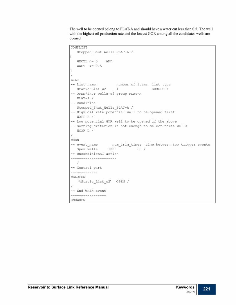
Reservoir to Surface Link Reference Manual KeywordsWHEN
221
The well to be opened belong to PLAT-A and should have a water cut less than 0.5. The well with the highest oil production rate and the lowest GOR among all the candidates wells are opened.
CONDLISTStopped_Shut_Wells_PLAT-A /
[WMCTL <= 0 ANDWWCT <= 0.5
]/LIST-- List name number of items list type
Static_List_w2 1 GROUPS /-- OPEN/SHUT wells of group PLAT-A
PLAT-A /-- condition
Stopped_Shut_Wells_PLAT-A /-- High oil rate potential well to be opened first
WOPP H /-- Low potential GOR well to be opened if the above-- sorting criterion is not enough to select three wells
WGOR L //WHEN-- event_name num_trig_times time between two trigger events
Open_wells 1000 60 /-- Unconditional action----------------------
/-- Control part-------------WELOPEN
‘%Static_List_w2’ OPEN //-- End WHEN event-----------------ENDWHEN
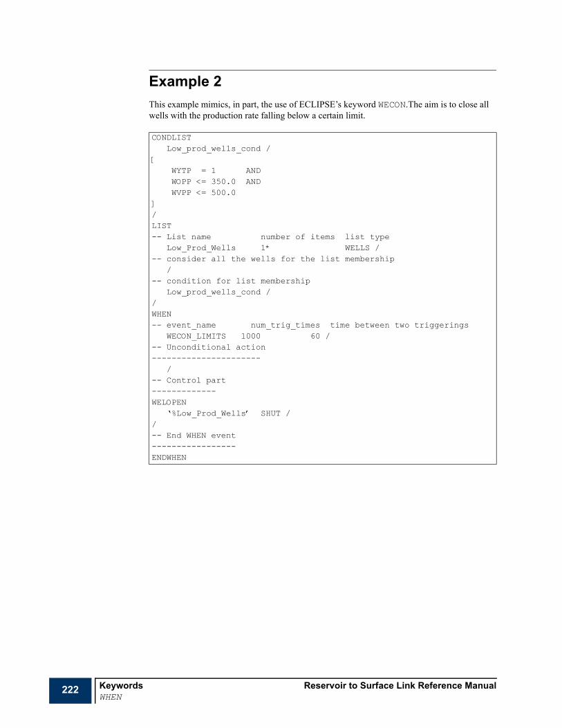
222 Keywords Reservoir to Surface Link Reference ManualWHEN
Example 2This example mimics, in part, the use of ECLIPSE’s keyword WECON.The aim is to close all wells with the production rate falling below a certain limit.
CONDLISTLow_prod_wells_cond /
[WYTP = 1 ANDWOPP <= 350.0 ANDWVPP <= 500.0
]/LIST-- List name number of items list type
Low_Prod_Wells 1* WELLS /-- consider all the wells for the list membership
/-- condition for list membership
Low_prod_wells_cond //WHEN-- event_name num_trig_times time between two triggerings
WECON_LIMITS 1000 60 /-- Unconditional action----------------------
/-- Control part-------------WELOPEN
‘%Low_Prod_Wells’ SHUT //-- End WHEN event-----------------ENDWHEN

Reservoir to Surface Link Reference Manual KeywordsWHEN
223
Example 3This example mimics the use of ECLIPSE’s keyword GECON. The aim is to close the well with the highest GOR that belongs to the highest GOR group. The well gets closed only if the field’s gas rate is > 150000.
CONDLISTHigh_Field_GRAT /
[GGPR > 150000.0
]/LIST-- List name number of items list type
GR_GOR 1 GROUPS /-- choose one group among all groups
/-- unconditional membership
/-- first sorting criterion: select the group with highest GOR first
GGOR H /-- first sorting criterion: group with lowest ORAT to be selected
GOPR L //LIST
WE_GOR 1 WELLS /-- consider only wells belonging to groups from the above list
‘%GR_GOR’ /-- unconditional membership
/-- first sorting criterion: select the well with highest GOR first
WGOR H /-- first sorting criterion: well with lowest ORAT to be selected
WOPR L //WHEN
WECON_LIMITS 1000 1* /-- condition------------
High_Field_GRAT /-- Control part-------------WELOPEN
‘%WE_GOR’ SHUT //-- End WHEN event-----------------ENDWHEN
224 Keywords Reservoir to Surface Link Reference ManualWHEN
Example 4This example illustrates the use of the WHEN keyword within a loop.
After every time step, this keyword does the following job:
WHILE there is at least a group with a GOR > 5.0 DO the following:
• Select the group with the highest GOR.
• Select the well with the highest GOR among all the wells belonging to the above group.
• Decreases by 50% the gas production rate of the selected well
• Re-tube the well (by allocating a new VFP table number to the well)
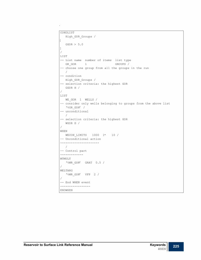
Reservoir to Surface Link Reference Manual KeywordsWHEN
225
.
CONDLISTHigh_GOR_Groups /
[GGOR > 5.0
]/LIST-- List name number of items list type
GR_GOR 1 GROUPS /-- choose one group from all the groups in the run
/-- condition
High_GOR_Groups /-- selection criteria: the highest GOR
GGOR H //LIST
WE_GOR 1 WELLS /-- consider only wells belonging to groups from the above list
‘%GR_GOR’ /-- unconditional
/-- selection criteria: the highest GOR
WGOR H //WHEN
WECON_LIMITS 1000 1* 10 /-- Unconditional action----------------------
/-- Control part-------------WTMULT
‘%WR_GOR’ GRAT 0.5 //WELTARG
‘%WR_GOR’ VFP 2 //-- End WHEN event-----------------ENDWHEN
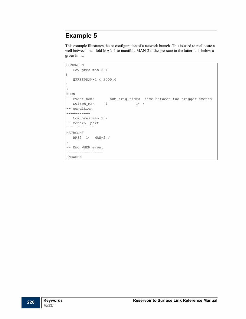
226 Keywords Reservoir to Surface Link Reference ManualWHEN
Example 5This example illustrates the re-configuration of a network branch. This is used to reallocate a well between manifold MAN-1 to manifold MAN-2 if the pressure in the latter falls below a given limit.
CONDWHENLow_pres_man_2 /
[NPRES@MAN-2 < 2000.0
]/WHEN-- event_name num_trig_times time between two trigger events
Switch_Man 1 1* /-- condition-----------
Low_pres_man_2 /-- Control part-------------NETBCONF
BR32 1* MAN-2 //-- End WHEN event-----------------ENDWHEN
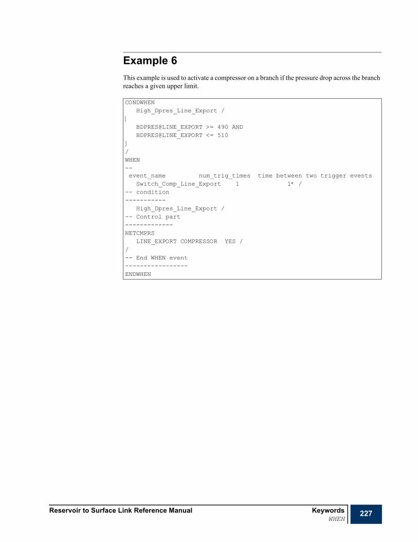
Reservoir to Surface Link Reference Manual KeywordsWHEN
227
Example 6This example is used to activate a compressor on a branch if the pressure drop across the branch reaches a given upper limit.
CONDWHENHigh_Dpres_Line_Export /
[BDPRES@LINE_EXPORT >= 490 ANDBDPRES@LINE_EXPORT <= 510
]/WHEN--event_name num_trig_times time between two trigger events
Switch_Comp_Line_Export 1 1* /-- condition-----------
High_Dpres_Line_Export /-- Control part-------------NETCMPRS
LINE_EXPORT COMPRESSOR YES //-- End WHEN event-----------------ENDWHEN

228 Keywords Reservoir to Surface Link Reference ManualWLIFTOPT
WLIFTOPT Sets well artificial lift optionsThe keyword sets well artificial lift options. The keyword is followed by any number of records, each containing the following items of data, and each terminated with a slash (/). The set of records must end with a blank record, containing only a slash.
1 Well name or Well Group Name
See "Special characters" on page 20 and "Defaulting tasks" on page 21 for details about naming conventions.
The use of a group name implies that all wells subordinate to the group will be considered. Note that only groups that contain wells may be specified.
2 Transfer a wells lift gas to the coupled network well
When a gas lifted well is coupled to a source in a network at top hole, the gas lift is achieved by specifying an artificial lift quantity (ALQ) for the well. This quantity is used by the wells VFP table to calculate the change in bottom hole pressure requirement associated with the specified lift gas quantity. ECLIPSE does not include the lift gas quantity with the produced gas. In order to properly account of the lift gas in the network, the lift gas must be added to the network sources
YES Include the wells lift gas in the network.
NO Do not include the wells lift gas in the network.
• DEFAULT: NO
3 ALQ multiplier
The multiplier for the ALQ value from the well.
• DEFAULT: 1.0
Example
RUNSPECPROPSSUMMARY
x SCHEDULE
WLIFTOPT-- Sets all wells prefixed with P to include lift gas
P*@RES1 YES 1.5 //

Reservoir to Surface Link Reference Manual KeywordsWNETDP
229
WNETDP Additional pressure drop between network node and wellThe keyword applies an additional fixed pressure drop between a well and its (or its group’s) corresponding network boundary node. The keyword is only needed if:
• there is a surface network present, and
• the THP limit of one or more wells should be offset from the pressure of its corresponding boundary node in the network.
Normally each well’s THP limit is set equal to the pressure at its (or its group’s) corresponding boundary node in the network. But if a fixed pressure drop is specified with this keyword for a well, the well's THP is set as follows:
• for a production well in a production network,
well THP = boundary node pressure + fixed pressure drop for well
• for an injection well in an injection network,
well THP = boundary node pressure - fixed pressure drop for well.
The keyword can also be used to isolate individual wells from the effects of the network. If the fixed pressure drop is set to a value greater than or equal to 1.0E10, the well's THP limit remains unchanged by the network balancing calculation and is not set equal to the boundary node pressure. The well's flow, however, is still incorporated in the network flows.
The keyword is followed by any number of records, each containing the following items of data, and each terminated with a slash (/). The set of records must end with a blank record, containing only a slash.
1 Well name
See "Special characters" on page 20 and "Defaulting tasks" on page 21 for details about naming conventions.
2 Fixed pressure drop between the well and its group’s network node
A value greater than or equal to 1.0E10 causes the well's THP limit to become independent of its group's nodal pressure. It remains constant unless changed manually in the keyword data.
• UNITS: bars (METRIC), psi (FIELD), atm (PVT-M).
• DEFAULT: 0.0
Example
RUNSPECPROPSSUMMARY
x SCHEDULE
WNETDPPROD1@RES1 20.0 /PROD2@RES2 30.0 //

230 Keywords Reservoir to Surface Link Reference ManualWRITEDBG
WRITEDBG Output debug informationThis keyword specifies the data to be written to the debug file. The file is primarily intended for use by the program developers, and the function of the output controls may change from one version to another. Many of the controls produce vast amounts of output and should be used with extreme caution. An empty debug file is generated if WRITEDBG is not used.
The keyword is followed by a number of records each containing up to 2 items and terminated with a slash (/). The set of records should be terminated with a blank record containing just a slash.
1 Mnemonic representing the quantity for which the debugging in formation is required.
2 Debugging level
0 switches off the debugging for the mnemonic in item 1.
1 full debugging information.
• DEFAULT: 0
The following is the list of mnemonics:
BODELUMP Output black oil delumping details.
FLASH Output flash calculation details.
FEVENTS Output for lists information (see LIST).
MAPPING Output data structure and boundary nodes mapping details.
MESSAGES Output runtime messages.
NETBAL Output network balancing details including network boundary nodes setting at each balancing iteration.
TIMING Display timing information for all tasks at the end of the DBG file.
XML Create XML output file.
Example
x RUNSPECx PROPSx SUMMARYx SCHEDULE
WRITEDBGMESSAGES 0 /MAPPING 1 /NETBAL 0 //
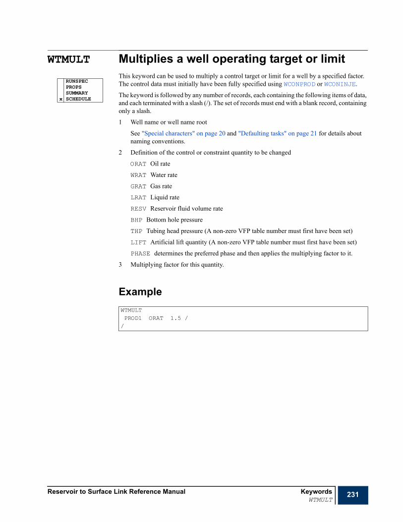
Reservoir to Surface Link Reference Manual KeywordsWTMULT
231
WTMULT Multiplies a well operating target or limitThis keyword can be used to multiply a control target or limit for a well by a specified factor. The control data must initially have been fully specified using WCONPROD or WCONINJE.
The keyword is followed by any number of records, each containing the following items of data, and each terminated with a slash (/). The set of records must end with a blank record, containing only a slash.
1 Well name or well name root
See "Special characters" on page 20 and "Defaulting tasks" on page 21 for details about naming conventions.
2 Definition of the control or constraint quantity to be changed
ORAT Oil rate
WRAT Water rate
GRAT Gas rate
LRAT Liquid rate
RESV Reservoir fluid volume rate
BHP Bottom hole pressure
THP Tubing head pressure (A non-zero VFP table number must first have been set)
LIFT Artificial lift quantity (A non-zero VFP table number must first have been set)
PHASE determines the preferred phase and then applies the multiplying factor to it.
3 Multiplying factor for this quantity.
Example
RUNSPECPROPSSUMMARY
x SCHEDULE
WTMULTPROD1 ORAT 1.5 //

232 Keywords Reservoir to Surface Link Reference ManualXMFVP
XMFVP Liquid mole fraction with respect to pressure table The data comprises a table of liquid mole fraction with respect to liquid dewpoint pressure data. Each table consists of columns of data, and is terminated with a slash (/).
Column: 1 Liquid bubblepoint pressure values.
The values should increase monotonically down the column.
• UNITS: barsa (METRIC), psia (FIELD), atma (PVT-M)
2 to
The corresponding values of , the liquid phase mole fractions. The mole fractions specified must add up to unity, and the program checks that this is the case.
The maximum number of XMVFP tables as well as the maximum number of rows in a table are set using MFVPDDIM. The number of components should be previously set using NCOMPS.
Note The FLUID number and the number of components corresponding to this FLUID should be previously set using FLUID and NCOMPS, respectively.
RUNSPECx PROPS
SUMMARYSCHEDULE
Nc 1+
Nc 1+
xi Nc

Reservoir to Surface Link Reference Manual KeywordsXMFVP
233
Example
XMFVP3900 0.00557807903095984
0.02916563459089590.4746269936939280.1529996679793210.07723182697554370.1027561500906060.06566091034542440.04282974299220640.03047029510446440.0186806991966491
4200 0.006196436533907020.03026836369542620.500627761095860.1523725596239540.0738250403312280.09482752672290460.05940544368087970.03852328017891520.02726187385330840.0166917142836176
4520 0.00689436131530850.03139137397234570.527788841907880.1515074782033830.07032694505097650.08676184930879550.05294984931422750.03403482622737170.02382707296190040.0145174017378115
/

234 Keywords Reservoir to Surface Link Reference ManualXMFVRS
XMFVRS Liquid mole fraction with respect to the liquid phase gas to oil ratio table The data comprises a table of liquid mole fraction with respect to liquid phase gas to oil ratio ( ) data. Each table consists of columns of data, and is terminated with a slash (/).
Column: 1 values.
The values should increase monotonically down the column.
• UNITS: sm3/sm3 (METRIC), Mscf/stb (FIELD), sm3/sm3 (PVT-M)
2 to
The corresponding values of , the liquid phase mole fractions. The mole fractions specified must add up to unity, and the program checks that this is the case.
The maximum number of XMFVRS tables as well as the maximum number of rows in a table are set using MFVPDDIM. The number of components should be previously set using NCOMPS.
Note The FLUID number and the number of components corresponding to this FLUID should be previously set using FLUID and NCOMPS, respectively.
RUNSPECx PROPS
SUMMARYSCHEDULE
Rs Nc 1+
Rs
Nc 1+
xi Nc

Reservoir to Surface Link Reference Manual KeywordsXMFVRS
235
ExampleXMFVRS1.3900 0.00557807903095984
0.02916563459089590.4746269936939280.1529996679793210.07723182697554370.1027561500906060.06566091034542440.04282974299220640.03047029510446440.0186806991966491
1.4200 0.006196436533907020.03026836369542620.500627761095860.1523725596239540.0738250403312280.09482752672290460.05940544368087970.03852328017891520.02726187385330840.0166917142836176
1.4520 0.00689436131530850.03139137397234570.527788841907880.1515074782033830.07032694505097650.08676184930879550.05294984931422750.03403482622737170.02382707296190040.0145174017378115
/

236 Keywords Reservoir to Surface Link Reference ManualYMFVP
YMFVP Vapor mole fraction with respect to pressure table The data comprises a table of vapor mole fraction with respect to vapor dew point pressure data. Each table consists of columns of data, and is terminated with a slash (/).
Column: 1 Vapor dew point pressure values.
The values should increase monotonically down the column.
• UNITS: barsa (METRIC), psia (FIELD), atma (PVT-M)
Column 2 to
The corresponding values of , the vapor phase mole fractions. The mole fractions specified must add up to unity, and the program checks that this is the case.
The maximum number of YMVFP tables as well as the maximum number of rows in a table are set using MFVPDDIM. The number of components should be previously set using NCOMPS.
Note The FLUID number and the number of components corresponding to this FLUID should be previously set using FLUID and NCOMPS, respectively.
RUNSPECx PROPS
SUMMARYSCHEDULE
Nc 1+
Nc 1+
yi Nc
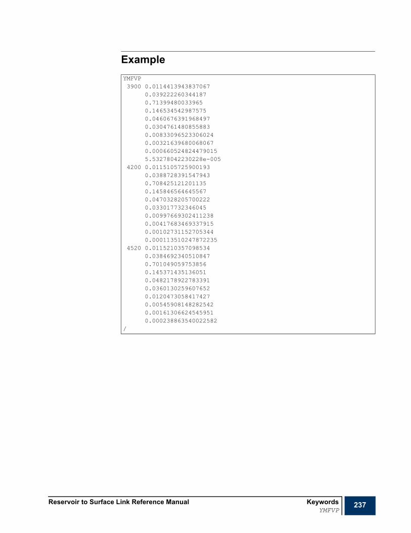
Reservoir to Surface Link Reference Manual KeywordsYMFVP
237
ExampleYMFVP3900 0.0114413943837067
0.0392222603441870.713994800339650.1465345429875750.04606763919684970.03047614808558830.008330965233060240.003216396800680670.0006605248244790155.53278042230228e-005
4200 0.01151057259001930.03887283915479430.7084251212011350.1458465646455670.04703282057002220.0330177323460450.009976693024112380.004176834693379150.001027311527053440.000113510247872235
4520 0.01152103570985340.03846923405108470.7010490597538560.1453714351360510.04821789227833910.03601302596076520.01204730584174270.005459081482825420.001613066245459510.000238863540022582
/
238 Keywords Reservoir to Surface Link Reference ManualYMFVRV
YMFVRV Vapor mole fraction with respect to the vapor phase oil to gas ratio table The data comprises a table of vapor mole fraction with respect to vapor phase oil to gas ratio ( ) data. Each table consists of columns of data, and is terminated with a slash (/).
Column:
1 values.
The values should increase monotonically down the column.
• UNITS: sm3/sm3 (METRIC), stb/Mscf (FIELD), sm3/sm3 (PVT-M)
2 to
The corresponding values of , the vapor phase mole fractions. The mole fractions specified must add up to unity, and the program checks that this is the case.
The maximum number of YMFVRV tables as well as the maximum number of rows in a table are set using MFVPDDIM. The number of components should be previously set using NCOMPS.
Note The FLUID number and the number of components corresponding to this FLUID should be previously set using FLUID and NCOMPS, respectively.
RUNSPECx PROPS
SUMMARYSCHEDULE
Rv Nc 1+
Rv
Nc 1+
yi Nc
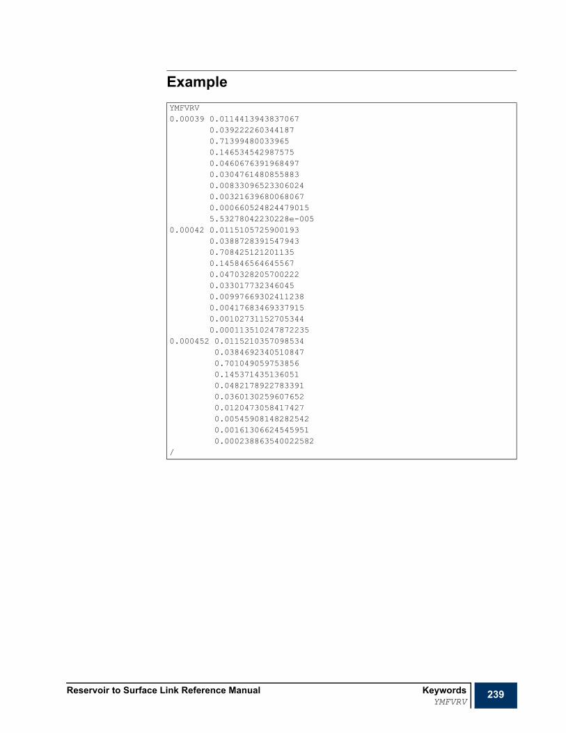
Reservoir to Surface Link Reference Manual KeywordsYMFVRV
239
ExampleYMFVRV0.00039 0.0114413943837067
0.0392222603441870.713994800339650.1465345429875750.04606763919684970.03047614808558830.008330965233060240.003216396800680670.0006605248244790155.53278042230228e-005
0.00042 0.01151057259001930.03887283915479430.7084251212011350.1458465646455670.04703282057002220.0330177323460450.009976693024112380.004176834693379150.001027311527053440.000113510247872235
0.000452 0.01152103570985340.03846923405108470.7010490597538560.1453714351360510.04821789227833910.03601302596076520.01204730584174270.005459081482825420.001613066245459510.000238863540022582
/

240 Keywords Reservoir to Surface Link Reference ManualZCRIT
ZCRIT Critical Z-factorsIn a FLUID with components, this keyword defines the critical Z-factors for each component. The keyword should be followed by a record of values terminated with a slash (/).
Note The FLUID number and the number of components corresponding to this FLUID should be previously set using FLUID and NCOMPS, respectively. VCRIT is an alternative to ZCRIT.
Example
RUNSPECx PROPS
SUMMARYSCHEDULE
-- ... components FLUIDZCRIT1.0 0.96 0.994 0.991 /
Nc
Nc

Reservoir to Surface Link Reference Manual Lookup Table ModuleWhat is the Lookup Table module?
241
Chapter 6Lookup Table Module
What is the Lookup Table module?The Lookup Table module is a fast proxy model of a reservoir that may be used as an alternative to a sophisticated reservoir model such as a reservoir simulator or a material balance model.
The lookup table module has two modes of operation:
• Standalone
This is a fairly trivial application of the Lookup Table module. However, it is useful when checking the consistency between the Lookup Table simulation and the reservoir simulation used to create the table data. For example, if the table data is generated from an ECLIPSE simulation, a properly configured lookup table proxy should produce similar results.
• Interactive
The lookup table proxy module implements the OpenECLIPSE interface. This means that it may be controlled by a master application, such as R2SL, in exactly the same way as ECLIPSE. In this respect, the Lookup Table model may be used to replace ECLIPSE in a coupled surface/sub-surface simulation in applications where computation speed is critical (for example optimization) or a faithful reservoir model is not required.

242 Lookup Table Module Reservoir to Surface Link Reference ManualData file overview
Data file overviewA lookup table data input file is split into sections, each of which is introduced by a keyword. A list of all section header keywords is given in "Data file sections" on page 242, together with a brief description of the contents of each section. A more detailed breakdown of the section contents may be found in the section overviews, which follow immediately after this general overview.
After the section overviews, this chapter contains a detailed description of the data for each keyword, in alphabetical keyword order. A flag table under each keyword heading indicates the section(s) in which the keyword is entered.
Data file sections
The sections must be specified in the order shown above.
It is recommended that the body of sections that are not frequently changed be held in separate files, which may be included in the data using the INCLUDE keyword.
Data file structureThe controller data file consists of a series of keywords and their associated data, similar to the ECLIPSE data files. Apart from few exceptions (which is mentioned in appropriate keywords), each keyword can appear anywhere in the data file within applicable section(s).
KeywordsThe keywords in the input data file are each of up to 8 characters in length and must start in column 1. All characters up to column 8 are significant. Any characters on the same line as a keyword from column 9 onwards is treated as a comment.
Table 6.1 Lookup Data file sections
Notes Keyword DescriptionRequired RUNSPEC This section contains initialization data that is required before the
simulation can start. This includes the problem dimensions for memory allocation and the lookup table definitions
Required SCHEDULE Specifies the operations to be simulated (well specifications and well production and injection controls) and the times at which output reports are required.

Reservoir to Surface Link Reference Manual Lookup Table ModuleData file overview
243
Keyword dataThe data for each keyword should follow that keyword on a new line. The keyword data is generally input as one or more records. Each record should start on a new line and is terminated with a slash (/). Within each record, the data may span one or more lines; line breaks are not significant. For keywords having a variable number of data records, the set of records should be terminated with a blank record containing only the slash terminator.
Default valuesCertain items of data can be defaulted to a built-in default value. The keyword description indicates when defaults can be applied. There are two ways of setting quantities to their default values. Firstly, by ending a data record prematurely with a slash (/) the quantities remaining unspecified are set to their default values. Secondly, selected quantities positioned before the slash can be defaulted by entering n* where n is the number of consecutive quantities to be defaulted. For example, 3* causes the next three quantities in the keyword data to be given their default values. There must be no blank space between the number and the asterisk. If there is only one item at a time to be defaulted, then 1* must be entered. An asterisk by itself is not sufficient.
An example would be the following line, in which TABDIMS is used to define the up-front memory requirements for the number lookup table application. The first item in the keyword is telling the application to allocate sufficient memory for 10 lookup tables. The following three items are set to their default values.
In the keyword set the following:.
Character stringsWhen character information is to be entered (such as group names for instance or mnemonics for instance), these may be optionally entered within quotes. Thus the example above is equivalent to:
Such quotes are only usually required if a name contains embedded blanks, starts with a number or contains non-alphanumeric characters. Quotes are also required when the wildcard * (or the special character @) character is used for well, group, node or branch name roots.
Special charactersThe following naming conventions apply for a well name. Similar naming conventions apply for groups, nodes and branches.
'PA1' Well with the name PA1 that belongs to the presently defaulted task.
'P*' All wells starting with the letter P that belong to the presently defaulted task.
TABDIMS10 3* /
GCONINJE'MAN-C' 'GAS' 'VREP' 150000 1* 2*1.0 3* 'PL-A' 'MAN-C' //

244 Lookup Table Module Reservoir to Surface Link Reference ManualData file overview
CommentsAny lines beginning with the two characters ‘--’ are treated as comments, and are ignored by the controller. Comment lines (and blank lines also) may be inserted anywhere in the data file. Comments may also be added to the end of lines of data by beginning the comment with the two characters ‘--’, but in this case the comments must not contain any quotes.
• Comments can also be included, without the two characters ‘--’, on the same line after a slash (/) that is used to terminate a data record.
Global keywordsSome general keywords may occur in any section (or in more than one section) of the data file. These keywords and brief descriptions of their functions are listed below.
Reading and echoing the input file The ECHO and NOECHO keywords turn on and off the echoing of the input file to the print file. The initial default is echoing on.
The INCLUDE keyword enables data to be read from another named file. It is followed by the name of a file from which input is to be taken. Once read, the file is closed, and input resumed from the main file, starting from the keyword after the INCLUDE.
An example would be:
Controlling debug The WRITEDBG keyword controls output to the debug file. This is intended mainly for program development purposes.
Ending input files The END keyword terminates the reading of data prior to the actual end of an input file. The program does not echo or process data after this. END may be used in an INCLUDE file. To end reading of an INCLUDE file prior to the actual end of file, and return control to the main input file, ENDINC may be used. END and ENDINC are generated automatically at the actual end of the relevant files, and so normally need not be used.
INCLUDE'TABLE_1.INC' /

Reservoir to Surface Link Reference Manual Lookup Table ModuleData file overview
245
List of global keywords
RUNSPEC section overviewThis section contains all dimensioning keywords (needed for memory allocation) as well as all other keywords that provide information that cannot be set/modified during the run (with a few exceptions). Keywords can appear in any order in this section, with a few exceptions shown below and in appropriate keywords.
RUNSPEC keywords
SCHEDULE section overview
The SCHEDULE section specifies the operations to be simulated (production and injection controls and constraints) and the times at which output reports are required.
All keywords in this section are optional, except for those necessary to define the nodes/wells/groups mapping (if needed).
Table 6.2 Lookup Global keywords
Keyword DescriptionECHO Switches on the echo of the data printed at the start of each run.END Terminates reading the data.ENDINC Terminates reading the INCLUDE file and returns to the main data file.INCLUDE Inserts the contents of a specified fileMESSAGES Sets print and stop message limitsNOECHO Switches off the echo of the data printed at the start of each run.WRITEDBG Outputs debugging information
Table 6.3 Lookup RUNSPEC keywords
Keyword DescriptionLOOKUP Supplies a two dimensional lookup table that is used by wells defined in
the SCHEDULE section.START Supplies the start date of the simulation.TABDIMS Sets maximum dimensions for memory allocation.TITLE Messages level from a taskUNITS Unit convention for data input/output
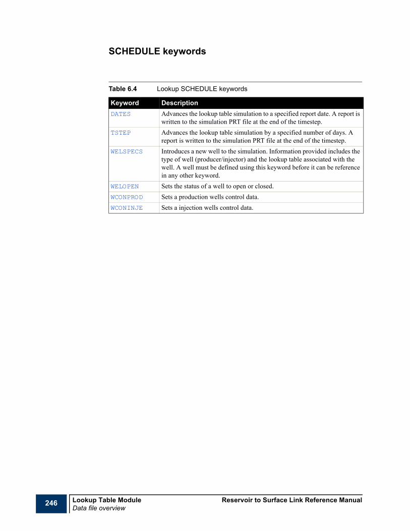
246 Lookup Table Module Reservoir to Surface Link Reference ManualData file overview
SCHEDULE keywords
Table 6.4 Lookup SCHEDULE keywords
Keyword DescriptionDATES Advances the lookup table simulation to a specified report date. A report is
written to the simulation PRT file at the end of the timestep.TSTEP Advances the lookup table simulation by a specified number of days. A
report is written to the simulation PRT file at the end of the timestep.WELSPECS Introduces a new well to the simulation. Information provided includes the
type of well (producer/injector) and the lookup table associated with the well. A well must be defined using this keyword before it can be reference in any other keyword.
WELOPEN Sets the status of a well to open or closed.WCONPROD Sets a production wells control data.WCONINJE Sets a injection wells control data.
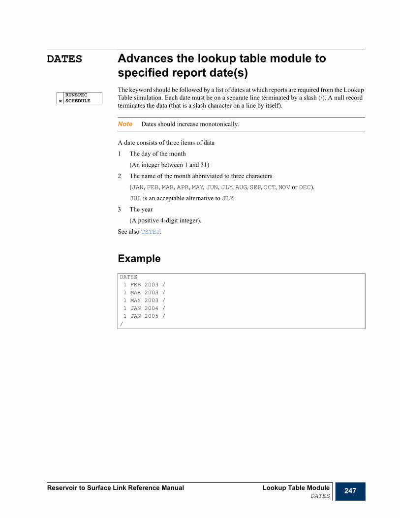
Reservoir to Surface Link Reference Manual Lookup Table ModuleDATES
247
DATES Advances the lookup table module to specified report date(s)The keyword should be followed by a list of dates at which reports are required from the Lookup Table simulation. Each date must be on a separate line terminated by a slash (/). A null record terminates the data (that is a slash character on a line by itself).
Note Dates should increase monotonically.
A date consists of three items of data
1 The day of the month
(An integer between 1 and 31)
2 The name of the month abbreviated to three characters
(JAN, FEB, MAR, APR, MAY, JUN, JLY, AUG, SEP, OCT, NOV or DEC).
JUL is an acceptable alternative to JLY.
3 The year
(A positive 4-digit integer).
See also TSTEP.
Example
RUNSPECx SCHEDULE
DATES1 FEB 2003 /1 MAR 2003 /1 MAY 2003 /1 JAN 2004 /1 JAN 2005 //

248 Lookup Table Module Reservoir to Surface Link Reference ManualECHO
ECHO Switches echo output onThe keyword turns on the echoing of the input file to the Print file at the start of the run. This echoing may be disabled using NOECHO, for example when entering large machine generated input files.
The default status for echoing is on. You can set this to off using NOECHO.
ECHO is normally only required, therefore, to turn echoing back on after a NOECHO keyword.
ECHO and NOECHO may be specified in any section, and any number of times in an input file.
x RUNSPECx SCHEDULE

Reservoir to Surface Link Reference Manual Lookup Table ModuleEND
249
END Logical end of input fileThis keyword terminates the input of data.
The END keyword need not be the actual end of the input file. However, if no END keyword is provided, one is generated at the end of the input data file.
END has no arguments.
x RUNSPECx SCHEDULE

250 Lookup Table Module Reservoir to Surface Link Reference ManualENDINC
ENDINC Logical end of include fileThe ENDINC keyword terminates the input of data from an INCLUDE file, returning control to the reading of the main file.
This keyword should not normally be entered, as an ENDINC is generated automatically at the end of the included file. It may, however, be used to end the reading of an included file before the actual end of file.
x RUNSPECx SCHEDULE

Reservoir to Surface Link Reference Manual Lookup Table ModuleINCLUDE
251
INCLUDE Include the contents of another named fileThe keyword should be followed by the name of a file from which input is to be taken. This file is opened, and read to the end of the file unless an ENDINC keyword is encountered. The file is then closed, and input resumed from the main file, starting from the next keyword after the INCLUDE keyword.
The INCLUDE file name may have up to 132 characters.
The data should be terminated by a slash (/).
Nested INCLUDE files are possible.
ExampleThis example causes the program to continue input from the file FLUID1.INC. At the end of that file, the program switches back to the next keyword in the current file.
x RUNSPECx SCHEDULE
INCLUDEFLUID1.INC /

252 Lookup Table Module Reservoir to Surface Link Reference ManualLOOKUP
LOOKUP Specifies a Lookup Table definitionThe keyword specifies a lookup table definition. The keyword consists of three record, each terminated with a slash.
Record 11 Lookup table number.
This number is an unique identifier for the lookup table. It is used in the WELSPECS keyword as a means of identifying the lookup table.
2 The source of the lookup table.
WELL Table was generated from well data
• DEFAULT: WELL
3 Lookup table label.
Record 21 Independent variable column header
TIME Simulation time
• Units: days (FIELD), days (METRIC)
WOPT Well Cumulative Oil Production
• Units: stb (FIELD), sm3 (METRIC)
WWPT Well Cumulative Water Production
• Units: stb (FIELD), sm3 (METRIC)
WGPT Well Cumulative Gas Production
• Units: Mscf (FIELD), sm3 (METRIC)
WWIT Well Cumulative Water Injection
• Units: stb (FIELD), sm3 (METRIC)
WGIT Well Cumulative Gas Injection
• Units: Mscf (FIELD), sm3 (METRIC)
2 Dependant variable columns.
WBHP Well bottom hole pressure
• Units: psia (FIELD), bara (METRIC)
WWCT Well Water cut.
• Units: Dimensionless (STB/STB)
WTHP Well top hole pressure
• Units: psia (FIELD), bara (METRIC)
WGOR Well Gas to Oil ratio
• Units: Mscf/stb (FIELD), sm3/sm3 (METRIC)
X RUNSPECSCHEDULE

Reservoir to Surface Link Reference Manual Lookup Table ModuleLOOKUP
253
WWOR Well Water to Oil ratio
• Units: Mscf/Mscf (FIELD), sm3/sm3 (METRIC)
WOGR Well Oil to Gas ratio
• Units: stb/Mscf (FIELD), sm3/sm3 (METRIC)
WWGR Well Water to Gas ratio
• Units: stb/Mscf (FIELD), sm3/sm3 (METRIC)
WOWR Well Oil to Water ratio
• Units: stb/stb (FIELD), sm3/sm3 (METRIC)
WGWR Well Gas to Water ratio
• Units: Mscf/stb (FIELD), sm3/sm3 (METRIC)
WGLR Well Gas to Liquid ratio
• Units: Mscf/stb (FIELD), sm3/sm3 (METRIC)
WLGR Well Liquid to Gas ratio
• Units: stb/Mscf (FIELD), sm3/sm3 (METRIC)
WBHT Well bottom hole temperature
• Units: oF (FIELD), oC (METRIC)
WTHT Well top hole temperature
• Units: oF (FIELD), oC (METRIC)
WOIPRA Intercept of linearized oil phase inflow performance relationship
• Units: stb/d (FIELD), sm3/d (METRIC)
WOIPRB Slope of linearized oil phase inflow performance relationship
• Units: stb/d/psia (FIELD), sm3/d/psia (METRIC)
WWIPRA Intercept of linearized water phase inflow performance relationship
• Units: stb/d (FIELD), sm3/d (METRIC)
WWIPRB Slope of linearized water phase inflow performance relationship
• Units: stb/d/psia (FIELD), sm3/d/psia (METRIC)
WGIPRA Intercept of linearized gas phase inflow performance relationship
• Units: Mscf/d (FIELD), sm3/d (METRIC)
WGIPRB Slope of linearized gas phase inflow performance relationship
• Units: Mscf/d/psia (FIELD), sm3/d/psia (METRIC)
WOSD Well Oil Density at Surface Conditions
• Units: lb/STB (FIELD), kg/m3 (METRIC)
WWSD Well Water Density at Surface Conditions
• Units: lb/STB (FIELD), kg/m3 (METRIC)
WGSD Well Gas Density at Surface Conditions
• Units: lb/MSCF (FIELD), kg/m3 (METRIC)

254 Lookup Table Module Reservoir to Surface Link Reference ManualLOOKUP
WOPRS Solution (Vaporized) Oil Production Rate
• Units: STB/d (FIELD), sm3/d (METRIC)
WGPRS Solution (Dissolved) Gas Production Rate
• Units: Mscf/d (FIELD), sm3/d (METRIC)
WOPRF Free Oil Production Rate
• Units: STB/d (FIELD), sm3/d (METRIC)
WGPRF Free Gas Production Rate
• Units: Mscf/d (FIELD), sm3/d (METRIC)
WPSATL Average saturation pressure in the well's connected grid blocks weighted by liquid mass inflow rate
• Units: psia (FIELD), bara (METRIC)
WPSATV Average saturation pressure in the well's connected grid blocks weighted by vapor mass inflow rate
• Units: psia (FIELD), bara (METRIC)
WMIPRA Well molar rate IPR intercept based on: Q = A - B BHP
• Units: lbmol/d (FIELD), kmol/d (METRIC)
WMIPRB Well molar rate IPR gradient based on: Q = A - B BHP
• Units: lbmol/d/psi (FIELD), kmol/d/bar (METRIC)
Note The total number of items in this record should not exceed the maximum number of lookup table columns defined in the TABDIMS keyword.
Record 31 The body of the look table
A table of data consisting of N columns and M rows. The number of columns, N, must correspond to the number of header mnemonics specified in the previous record. Each column holds the numerical data associate with its header.
Note The total number of rows in the table, M, should not exceed the maximum number of rows defined in the TABDIMS keyword.

Reservoir to Surface Link Reference Manual Lookup Table ModuleLOOKUP
255
ExampleLOOKUP
1 WELL ‘LOOKUP_1’ /
WOPT WBHP WGOR WWOR /
0.0 3746.7 1.4998 0.004000.2 3755.3 0.001.4999 0.0015762.0 3868.9 0.001.5002 0.0052340.0 4057.2 0.001.5138 0.00128950.0 4175.3 0.001.5342 0.00192220.0 4289.3 0.001.5421 0.00258850.0 4382.0 0.001.6243 0.00332900.0 4443.4 0.002.0812 0.00407500.0 4511.7 0.002.6117 0.00498810.0 4622.5 0.003.7201 0.00632120.0 4745.0 0.004.6579 0.001129700.0 4739.9 0.003.0481 0.001293200.0 4795.5 0.004.9905 0.00/

256 Lookup Table Module Reservoir to Surface Link Reference ManualMESSAGES
MESSAGES Resets message print and stop limitsThis keyword can be used to reset the print and stop limits for messages of any severity type. There are 6 levels of severity:
1 = Message (Not an error, purely informative)
2 = Comment (Probably not a data error)
3 = Warning (Possibly a data error)
4 = Problem (Calculation difficulties)
5 = Error (Definitely a data error)
6 = Bug (Suspected programming error).
Printing of a particular type of message ceases after its print limit has been reached. The run stops if a particular type of message is generated more times than its stop limit. However, the run is switched into data checking mode if any error message is generated, so that no time step calculations are performed after the next TSTEP or DATES keyword.
The keyword should be followed by up to 12 integers, terminated by a slash (/). Repeat counts (for example 3*1000) and defaults (for example 2*) can be used if required. Any items defaulted or left unspecified will not be altered. The items are initialized with their default values.
1 Print limit for severity 1 messages
• DEFAULT: 1000000
2 Print limit for severity 2 messages
• DEFAULT: 1000000
3 Print limit for severity 3 messages
• DEFAULT: 10000
4 Print limit for severity 4 messages
• DEFAULT: 100
5 Print limit for severity 5 messages
• DEFAULT: 100
6 Print limit for severity 6 messages
• DEFAULT: 100
7 Stop limit for severity 1 messages
• DEFAULT: 1000000
8 Stop limit for severity 2 messages
• DEFAULT: 1000000
9 Stop limit for severity 3 messages
• DEFAULT: 10000
10 Stop limit for severity 4 messages
• DEFAULT: 100
11 Stop limit for severity 5 messages
• DEFAULT: 10
x RUNSPECx SCHEDULE

Reservoir to Surface Link Reference Manual Lookup Table ModuleMESSAGES
257
12 Stop limit for severity 6 messages
• DEFAULT 1
Note It is not advisable to alter the stop limits for messages of severity 5 and 6.
ExampleMESSAGES2* 10 5* 10000 / alters print and stop limits for warnings

258 Lookup Table Module Reservoir to Surface Link Reference ManualNOECHO
NOECHO Disable echoing of the input fileThe keyword causes the echo of the data input that is produced at the start of each run to be switched off from the next keyword until a subsequent ECHO keyword is encountered (or until the end of the data).
NOECHO may be used to reduce the amount of print-out from a run, or to avoid the output of large included files.
ECHO and NOECHO may be specified in any section, and any number of times in an input file.
The NOECHO keyword has no associated data.
x RUNSPECx SCHEDULE

Reservoir to Surface Link Reference Manual Lookup Table ModuleSTART
259
START Specifies a start dateThis keyword specifies the start date of the simulation. (Any report dates entered in the DATES keyword in the SCHEDULE section must be later than the start date.) The keyword is followed by 3 items of data, denoting the day, month and year of the start of the simulation, terminated with a slash (/).
1 Day
Day of the month (an integer between 1 and 31).
2 Month
Name of the month (JAN, FEB, MAR, APR, MAY, JUN, JUL, AUG, SEP, OCT, NOV, DEC).
• For July, the abbreviation JLY is a valid alternative.
3 Year
The year (a 4-figure integer).
• DEFAULT: 1 Jan 1990
Example
x RUNSPECx SCHEDULE
START12 FEB 1987 /

260 Lookup Table Module Reservoir to Surface Link Reference ManualTABDIMS
TABDIMS Maximum dimensions for memory allocationThe keyword is required only if the default dimensions are inadequate. If the keyword is not present, all items assume their default values.
Caution You are advised to use this keyword to enter adequate maximum dimensions to avoid unnecessary memory use by the controller.
The keyword is followed by one record, terminated with a slash (/), containing the following items.
1 Maximum number of tables in the lookup table module
• DEFAULT: 10
2 Maximum number of columns in each table
• DEFAULT: 10
3 Maximum number of rows in each table
• DEFAULT: 100
4 Maximum number of wells that may be specified
• DEFAULT: 10
Example
x RUNSPECSCHEDULE
TABDIMS2 6 50 2 /

Reservoir to Surface Link Reference Manual Lookup Table ModuleTITLE
261
TITLE Specify run titleThis enables the controller run's title to appear in the output files. The syntax is rather different from that of other keywords, the line after the TITLE keyword being read directly. No quotes or slash characters are required.
Example
x RUNSPECSCHEDULE
TITLEMultiple Reservoir Coupling + Production and Injection Networks

262 Lookup Table Module Reservoir to Surface Link Reference ManualTSTEP
TSTEP Advance the lookup table module over specified time interval(s)The keyword is followed by a list of one or more integers, terminated with a slash (/). Each integer represents a time interval through which all coupled simulations are to be advanced.
• UNITS:
days (METRIC), days (FIELD),
Note Repeat counts (for example 6*30) can be used if required (but no spaces before or after the asterisk).
See also DATES.
Example
RUNSPECx SCHEDULE
TSTEP31 28 31 30 31 3031 31 30 31 30 31 /
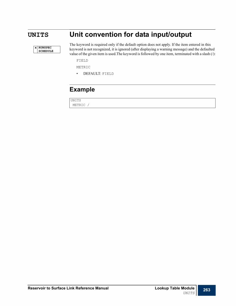
Reservoir to Surface Link Reference Manual Lookup Table ModuleUNITS
263
UNITS Unit convention for data input/outputThe keyword is required only if the default option does not apply. If the item entered in this keyword is not recognized, it is ignored (after displaying a warning message) and the defaulted value of the given item is used.The keyword is followed by one item, terminated with a slash (/):
FIELD
METRIC
• DEFAULT: FIELD
Example
x RUNSPECSCHEDULE
UNITSMETRIC /
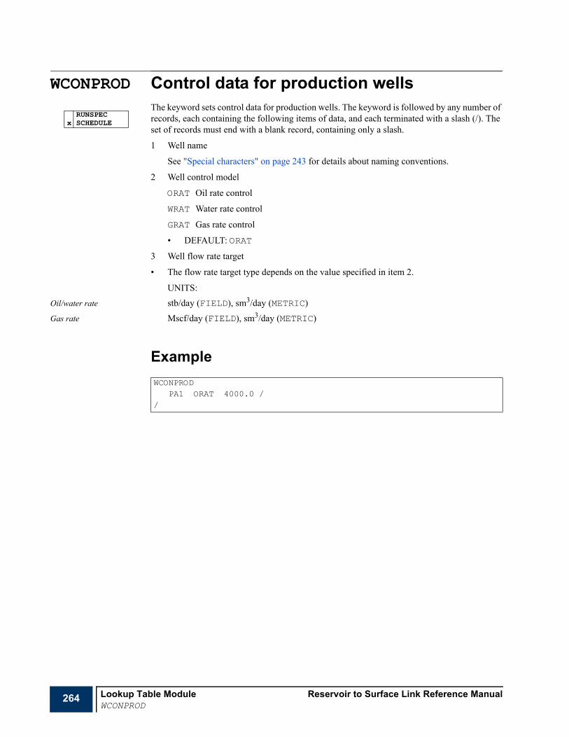
264 Lookup Table Module Reservoir to Surface Link Reference ManualWCONPROD
WCONPROD Control data for production wellsThe keyword sets control data for production wells. The keyword is followed by any number of records, each containing the following items of data, and each terminated with a slash (/). The set of records must end with a blank record, containing only a slash.
1 Well name
See "Special characters" on page 243 for details about naming conventions.
2 Well control model
ORAT Oil rate control
WRAT Water rate control
GRAT Gas rate control
• DEFAULT: ORAT
3 Well flow rate target
• The flow rate target type depends on the value specified in item 2.
UNITS:Oil/water rate stb/day (FIELD), sm3/day (METRIC)
Gas rate Mscf/day (FIELD), sm3/day (METRIC)
Example
RUNSPECx SCHEDULE
WCONPRODPA1 ORAT 4000.0 /
/
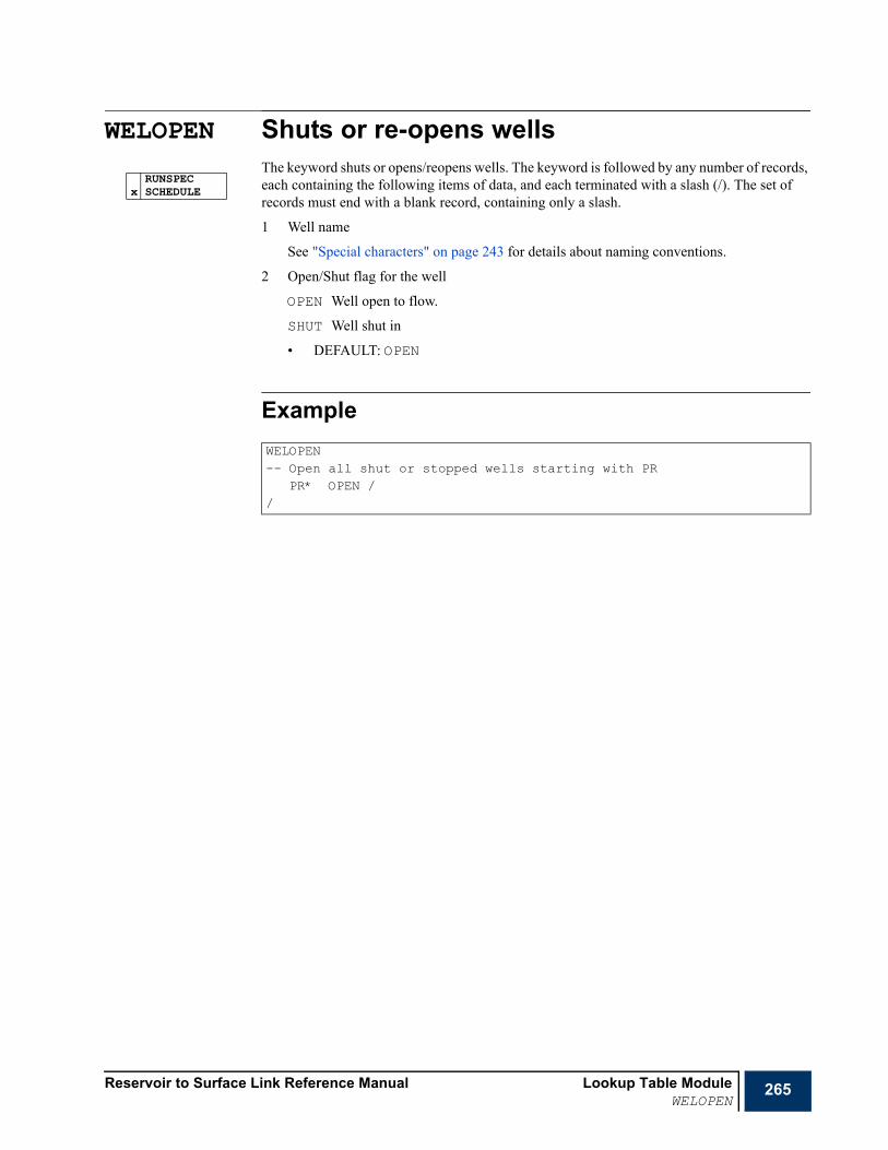
Reservoir to Surface Link Reference Manual Lookup Table ModuleWELOPEN
265
WELOPEN Shuts or re-opens wellsThe keyword shuts or opens/reopens wells. The keyword is followed by any number of records, each containing the following items of data, and each terminated with a slash (/). The set of records must end with a blank record, containing only a slash.
1 Well name
See "Special characters" on page 243 for details about naming conventions.
2 Open/Shut flag for the well
OPEN Well open to flow.
SHUT Well shut in
• DEFAULT: OPEN
Example
RUNSPECx SCHEDULE
WELOPEN-- Open all shut or stopped wells starting with PR
PR* OPEN //

266 Lookup Table Module Reservoir to Surface Link Reference ManualWELSPECS
WELSPECS General specification data for wellsThe keyword defines the specification data required for wells in the Lookup Table simulator. The keyword is followed by any number of records, each containing the following items of data, and each terminated with a slash (/). The set of records must end with a blank record, containing only a slash.
1 Well name
See "Special characters" on page 243 for details about naming conventions.
2 Lookup Table Number
This specifies the lookup table that is used to calculate the well properties.
Example
RUNSPECx SCHEDULE
WELSPECS-- Specify well PROD1 and assign it lookup table with index 1
PROD1 1 //
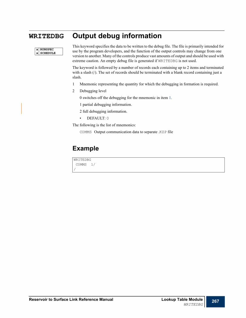
Reservoir to Surface Link Reference Manual Lookup Table ModuleWRITEDBG
267
WRITEDBG Output debug informationThis keyword specifies the data to be written to the debug file. The file is primarily intended for use by the program developers, and the function of the output controls may change from one version to another. Many of the controls produce vast amounts of output and should be used with extreme caution. An empty debug file is generated if WRITEDBG is not used.
The keyword is followed by a number of records each containing up to 2 items and terminated with a slash (/). The set of records should be terminated with a blank record containing just a slash.
1 Mnemonic representing the quantity for which the debugging in formation is required.
2 Debugging level
0 switches off the debugging for the mnemonic in item 1.
1 partial debugging information.
2 full debugging information.
• DEFAULT: 0
The following is the list of mnemonics:
COMMS Output communication data to separate .KZP file
Example
x RUNSPECx SCHEDULE
WRITEDBGCOMMS 1//

268 Lookup Table Module Reservoir to Surface Link Reference ManualWRITEDBG

Reservoir to Surface Link Reference Manual The Black Oil Tank ModelIntroduction
269
Chapter 7The Black Oil Tank Model
IntroductionThe Tank Model provides a simple analytical representation of an oil or gas reservoir. The reservoir is defined in terms of a finite volume of porous media containing either free gas, oil, dissolved gas and water (Live Oil) or free gas and water (Dry Gas). Given the reservoir dimensions, the initial conditions and the PVT properties of the fluids, the effects of production from and injection into the reservoir may be modeled by solving the material balance equations for the reservoir. This allows the calculation of the reservoir pressure at a given point in time taking into account the net changes in reservoir fluids. The primary features of the tank model are:
• The provision of a simple representation of a black oil or dry gas reservoir model for situations where a rigorous reservoir model is not required or unavailable. For example, the tank model could be used as a reservoir proxy model in an optimization problem.
• The tank model implements the OpenECLIPSE interface. This means that it may be controlled by an external master application. The primary application of this is R2SL, which allows reservoir models to be coupled to a surface network model.
The Tank Model uses a set of input data keywords that are similar to those employed by ECLIPSE and that exploit the same syntax.
The principles behind the Tank Model are discussed in"Tank Model" in the "Reservoir to Surface Link Technical Description"
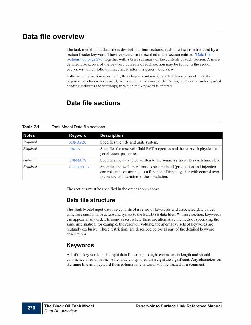
270 The Black Oil Tank Model Reservoir to Surface Link Reference ManualData file overview
Data file overviewThe tank model input data file is divided into four sections, each of which is introduced by a section header keyword. These keywords are described in the section entitled "Data file sections" on page 270, together with a brief summary of the contents of each section. A more detailed breakdown of the keyword contents of each section may be found in the section overviews, which follow immediately after this general overview.
Following the section overviews, this chapter contains a detailed description of the data requirements for each keyword, in alphabetical keyword order. A flag table under each keyword heading indicates the section(s) in which the keyword is entered.
Data file sections
The sections must be specified in the order shown above.
Data file structureThe Tank Model input data file consists of a series of keywords and associated data values which are similar in structure and syntax to the ECLIPSE data files. Within a section, keywords can appear in any order. In some cases, where there are alternative methods of specifying the same information, for example, the reservoir volume, the alternative sets of keywords are mutually exclusive. These restrictions are described below as part of the detailed keyword descriptions.
KeywordsAll of the keywords in the input data file are up to eight characters in length and should commence in column one. All characters up to column eight are significant. Any characters on the same line as a keyword from column nine onwards will be treated as a comment.
Table 7.1 Tank Model Data file sections
Notes Keyword DescriptionRequired RUNSPEC Specifies the title and units system.Required PROPS Specifies the reservoir fluid PVT properties and the reservoir physical and
geophysical properties.Optional SUMMARY Specifies the data to be written to the summary files after each time step.Required SCHEDULE Specifies the well operations to be simulated (production and injection
controls and constraints) as a function of time together with control over the nature and duration of the simulation.
Reservoir to Surface Link Reference Manual The Black Oil Tank ModelData file overview
271
Keyword dataWhere keywords require input data to be specified, the data should follow the keyword on a new line. The keyword data is usually specified in terms of one or more records. Each record should start on a new line and must be terminated by a forward slash (/) character. Within each record, the data may span one or more lines; in this context line breaks are not significant. For keywords having a variable number of data records, in addition to terminating each individual record with a forward slash character, the set of records should be terminated with a blank record containing an additional final forward slash character.
Default valuesFor some keywords, internally preassigned default values are available and hence the inclusion of these keywords is optional. In addition, where a keyword requires the specification of two or more data items, one or more of these items of data may be omitted. There are two ways of omitting input data items: firstly, by ending a data record prematurely with a forward slash (/) character, and secondly, by entering n* where n is the number of consecutive data items to be defaulted. For example, 3* causes the next three quantities in the keyword data to be defaulted. There must be no blank space between the number and the asterisk. If there is only one item at a time to be defaulted, then 1* must be entered. An asterisk by itself is not sufficient.
The consequences of omitting data in the manner described above is keyword dependent. For example, for the PVT table data specified using the PVTTAB keyword, the omission of a data item instructs the preprocessor to construct the missing value by linear interpolation about the nearest available columnar neighbors. In contrast, the omission of a data item in the WELLS keyword specifies that the existing value of the associated quantity should remain unchanged. If this value has not been assigned previously, this will be the internally assigned default value.
Character stringsWhen character information such a well name is to be entered, it should be entered without quotation marks and should not include embedded spaces. Well names may consist of any combination of alpha-numeric and non alpha-numeric characters in any order but excluding spaces and comment characters ‘--’.
CommentsAny blank lines or lines commencing with the two characters ‘--’ are treated as comments and are ignored by the input data processor. In addition, information on any line following the two comment characters will be ignored. It is therefore possible to add annotation in the form of in line comments following data items.
Global keywordsA number of global keywords may occur in more than one section. These are summarized below
Reading and echoing the input file The ECHO and NOECHO keywords turn on and off respectively the echoing of the input file to the output print file. The initial default is echoing off. The keywords may be used arbitrarily throughout the input data file to select or deselect the echoing of various portions of the input data file as required.

272 The Black Oil Tank Model Reservoir to Surface Link Reference ManualData file overview
The INCLUDE keyword enables data to be read from another named file. It is followed by the name of a file from which input is to be taken. Once read, the file is closed, and input resumed from the file containing the INCLUDE keyword, starting from the keyword following the INCLUDE keyword. Multiply nested included file operations are supported; however, in general, because of the comparatively small amounts of input data involved in specifying the tank model, it not anticipated that this facility will often be required in practice.
An example of an included file specification is shown below:
Ending input files The END keyword terminates the reading of an input data stream. The program does not echo or process data after encountering this keyword. This keyword may also be used from within an included file. If it is required to terminate reading from an included file prior to reaching the end, and return control to the parent input file, the ENDINC keyword may be used. This keyword is generated automatically at the actual end of an included file and hence normally need not be added. However, the main input file should always be terminated with the END keyword.
List of global keywords
RUNSPEC section overviewThe RUNSPEC section consists of a small number of keywords which may be used to specify basic controls over the operation of the tank model simulation. These keywords may be specified in any order, however, the presence of some keywords precludes the presence of others. All program memory requirements are allocated dynamically according to the nature of the simulation specified by the input data and hence no dimensioning keywords are required. This section may be omitted if none of the keywords are required.
INCLUDE'FLUID1.INC' /
Table 7.2 Global Tank Model keywords
Keyword DescriptionECHO Switches on the echo of the data printed at the start of each runEND Terminates reading the data.ENDINC Terminates reading the Include file and return to the main data file.INCLUDE Inserts the contents of a specified file.NOECHO Switches off the echo of the data printed at the start of each run.
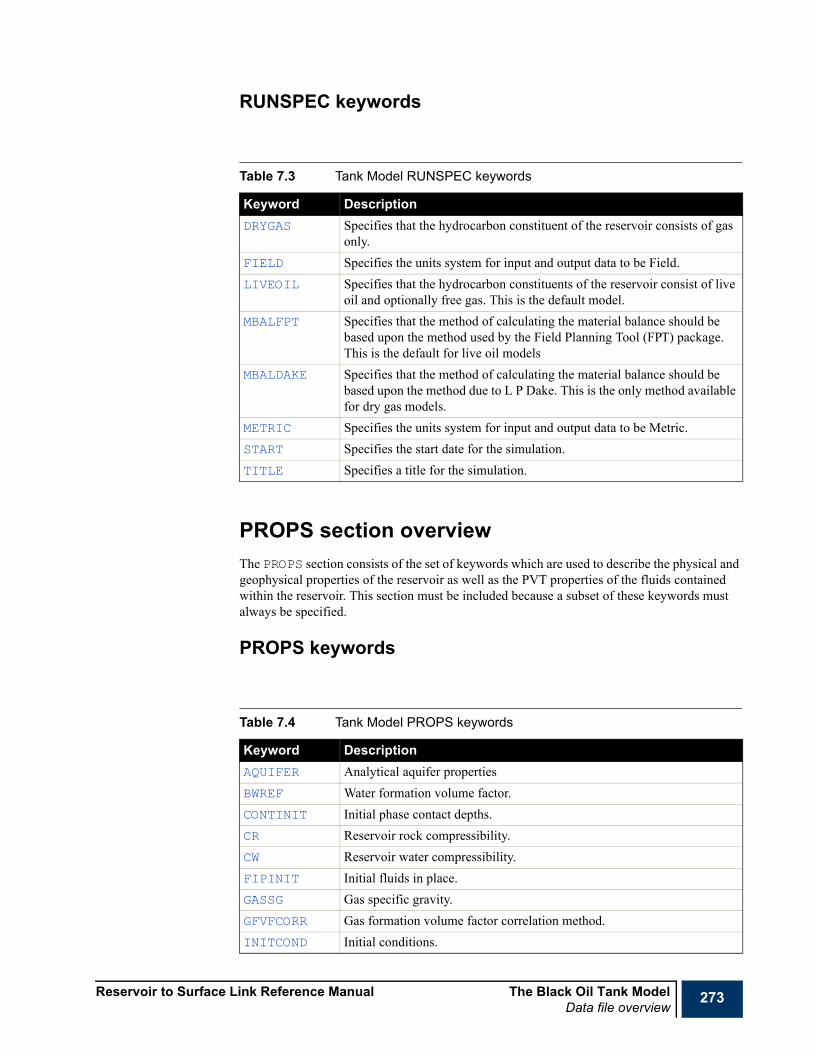
Reservoir to Surface Link Reference Manual The Black Oil Tank ModelData file overview
273
RUNSPEC keywords
PROPS section overviewThe PROPS section consists of the set of keywords which are used to describe the physical and geophysical properties of the reservoir as well as the PVT properties of the fluids contained within the reservoir. This section must be included because a subset of these keywords must always be specified.
PROPS keywords
Table 7.3 Tank Model RUNSPEC keywords
Keyword DescriptionDRYGAS Specifies that the hydrocarbon constituent of the reservoir consists of gas
only.FIELD Specifies the units system for input and output data to be Field.LIVEOIL Specifies that the hydrocarbon constituents of the reservoir consist of live
oil and optionally free gas. This is the default model.MBALFPT Specifies that the method of calculating the material balance should be
based upon the method used by the Field Planning Tool (FPT) package. This is the default for live oil models
MBALDAKE Specifies that the method of calculating the material balance should be based upon the method due to L P Dake. This is the only method available for dry gas models.
METRIC Specifies the units system for input and output data to be Metric.START Specifies the start date for the simulation.TITLE Specifies a title for the simulation.
Table 7.4 Tank Model PROPS keywords
Keyword DescriptionAQUIFER Analytical aquifer propertiesBWREF Water formation volume factor.CONTINIT Initial phase contact depths.CR Reservoir rock compressibility.CW Reservoir water compressibility.FIPINIT Initial fluids in place.GASSG Gas specific gravity.GFVFCORR Gas formation volume factor correlation method.INITCOND Initial conditions.

274 The Black Oil Tank Model Reservoir to Surface Link Reference ManualData file overview
SUMMARY Section overviewThe SUMMARY section specifies a number of variables which are to be written to SUMMARY files after each synchronized time step. The graphics post-processor may be used to display the variation of variables in the SUMMARY files with time and with each other. If the SUMMARY section is not specified, no SUMMARY files will be created.
Summary files may be written in the form of ELCIPSE Office observable files with the file extension .OBS. A separate file is written for the field data and for each individual well data set. The file names are constructed by appending the text sting _FIELD for the field data and _well for well data, where well denotes the well name.
SUMMARY vectorsWhen the REPORT keyword is used to specify that ECLIPSE Office observable format, files are to be written the summary vectors shown below in Table 3.1 will be output.
NTG Reservoir net to gross ratioOILAPI Oil API.OFVFCORR Oil formation volume factor correlation methodPBRSCORR Bubble point pressure and solution gas-oil ratio correlation method.PERM Reservoir permeability.PORO Reservoir porosity.PVTINT Internal PVT table construction control.PVTTAB Externally generated PVT tabular data for live oil and dry gas models.PVTTABDG Externally generated PVT tabular data for dry gas models only.RESCYL Reservoir cylindrical volume dimensions.RESVOL Reservoir depth versus area table volume dimensions.SGRW Gas saturation to residual waterSORG Oil saturation to residual gas.SORW Oil saturation to residual water.SWC Connate water saturation.ZFACCORR Gas Z-factor correlation method.
Table 7.5 Wells and Groups Output Summary Vector
Phase Field Well InformationOil FOPR WOPR Oil Production Rate
Oil FOPT WOPT Oil Production Total
Oil FOIR WOIR Oil Injection Rate
Oil FOIT WOIT Oil Injection Total
Table 7.4 Tank Model PROPS keywords
Keyword Description
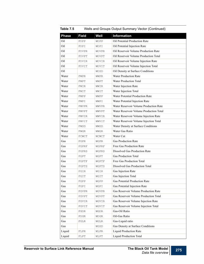
Reservoir to Surface Link Reference Manual The Black Oil Tank ModelData file overview
275
Oil FOPP WOPP Oil Potential Production Rate
Oil FOPI WOPI Oil Potential Injection Rate
Oil FOVPR WOVPR Oil Reservoir Volume Production Rate
Oil FOVPT WOVPT Oil Reservoir Volume Production Total
Oil FOVIR WOVIR Oil Reservoir Volume Injection Rate
Oil FOVIT WOVIT Oil Reservoir Volume Injection Total
Oil WOSD Oil Density at Surface Conditions
Water FWPR WWPR Water Production Rate
Water FWPT WWPT Water Production Total
Water FWIR WWIR Water Injection Rate
Water FWIT WWIT Water Injection Total
Water FWPP WWPP Water Potential Production Rate
Water FWPI WWPI Water Potential Injection Rate
Water FWVPR WWVPR Water Reservoir Volume Production Rate
Water FWVPT WWVPT Water Reservoir Volume Production Total
Water FWVIR WWVIR Water Reservoir Volume Injection Rate
Water FWVIT WWVIT Water Reservoir Volume Injection Total
Water FWSD WWSD Water Density at Surface Conditions
Water FWGR WWGR Water Gas Ratio
Water FCWCT WCWCT Water Cut
Gas FGPR WGPR Gas Production Rate
Gas FGPRF WGPRF Free Gas Production Rate
Gas FGPRS WGPRS Dissolved Gas Production Rate
Gas FGPT WGPT Gas Production Total
Gas FGPTF WGPTF Free Gas Production Total
Gas FGPTS WGPTS Dissolved Gas Production Total
Gas FGIR WGIR Gas Injection Rate
Gas FGIT WGIT Gas Injection Total
Gas FGPP WGPP Gas Potential Production Rate
Gas FGPI WGPI Gas Potential Injection Rate
Gas FGVPR WGVPR Gas Reservoir Volume Production Rate
Gas FGVPT WGVPT Gas Reservoir Volume Production Total
Gas FGVIR WGVIR Gas Reservoir Volume Injection Rate
Gas FGVIT WGVIT Gas Reservoir Volume Injection Total
Gas FGOR WGOR Gas-Oil Ratio
Gas FOGR WOGR Oil-Gas Ratio
Gas FGLR WGLR Gas-Liquid ratio
Gas WGSD Gas Density at Surface Conditions
Liquid FLPR WLPR Liquid Production Rate
Liquid FLPT WLPT Liquid Production Total
Table 7.5 Wells and Groups Output Summary Vector (Continued)
Phase Field Well Information

276 The Black Oil Tank Model Reservoir to Surface Link Reference ManualData file overview
Examples
If a dry gas model is specified, the oil phase summary vectors will be omitted.
SCHEDULE section overview
Liquid FLIR WLIR Liquid Injection Rate
Liquid FLIT WLIT Liquid Injection Total
Volume FVPR WVPR Reservoir Volume Production Rate
Volume FVPT WVPT Reservoir Volume Production Total
Volume FVIR WVIR Reservoir Volume Injection Rate
Volume FVIT WVIT Reservoir Volume Injection Total
Volume FVPP WVPP Reservoir Volume Potential Production Rate
Volume FVPI WVPI Reservoir Volume Potential Injection Rate
Volume FOVPI Reservoir Volume Oil Potential Injection Rate
Volume FWVPI Reservoir Volume Water Potential Injection Rate
Volume FGVPI Reservoir Volume Gas Potential Injection Rate
Aquifer FAQR Aquifer Production Rate
Aquifer FAQT Aquifer Production Total
Inflow WOIPRA Oil Inflow Performance Coefficient A
Inflow WOIPRB Oil Inflow Performance Coefficient B
Inflow WWIPRA Water Inflow Performance Coefficient A
Inflow WWIPRB Water Inflow Performance Coefficient B
Inflow WGIPRA Gas Inflow Performance Coefficient A
Inflow WGIPRB Gas Inflow Performance Coefficient B
Misc WBHP Bottom Hole Pressure
Misc WBHDEP Bottom Hole Pressure Depth
Misc WTHP Tubing Head Pressure
Misc WTHT Tubing Head Temperature
Misc FGOC WGOC Gas-Oil Contact Depth
Misc FGWC WGWC Gas-water Contact Depth
Misc FOWC WOWC Oil-Water Contact Depth
Misc FEFF WEFF Efficiency
Misc FPR Reservoir Pressure
REPORTOFFICEOBS/
Table 7.5 Wells and Groups Output Summary Vector (Continued)
Phase Field Well Information

Reservoir to Surface Link Reference Manual The Black Oil Tank ModelData file overview
277
The SCHEDULE section specifies the well properties, the production and injection events and the controls over the simulation process. All of the keywords in this section are optional and may be specified any number of times
SCHEDULE keywords
Table 7.6 Tank Model SCHEDULE keywords
Keyword DescriptionDATES Specifies a set of dates to which to advance the simulationDPMAX Specifies the maximum permitted change in reservoir pressure between
successive time steps.DTMAX Specifies the maximum permitted time interval between successive time
steps.MBERRMAX Specifies the maximum permitted error when solving the material balance
equation as a function of pressure.TIME Specifies a set of times to which to advance the simulationTSTEP Specifies a set of time steps by which to advance the simulation.WELLS Defines the properties of the wells.

278 The Black Oil Tank Model Reservoir to Surface Link Reference ManualUsing the Tank Model
Using the Tank ModelThe following example illustrates a simple LIVEOIL model in which the PVT data are specified using internally generated set of correlations. The initial reservoir pressure is above the bubble point pressure and hence initially there is only oil in place. With the exception of the SCHEDULE section, where the ordering of keywords has significance with respect to time, the ordering of keywords within a section is not significant.
In the RUNSPEC section, a title has been specified (TITLE), the input and output units system has been specified to be Field (FIELD), the echoing of the input keywords has been selected (ECHO) and the start date has been specified as 1 January 2000 (START). Any of these keywords could optionally have been omitted, whereupon the appropriate defaults would have been selected.
In the PROPS section, the bubble point pressure and solution gas-oil ratio correlation method has been specified to be Standing (PBRSCORR). The oil formation volume factor correlation method has been specified to be Standing (OFVFCORR). The gas Z-factor correlation method has been specified to be Hall and Yarborough (ZFACCORR). Finally, the gas formation volume factor has been specified to be Spivey and McCain (GFVFCORR). All four of these keywords could have been omitted because in each case the default correlation method has been selected.
The water formation volume factor has been specified to be a function of pressure and has been defined in terms of a reference pressure and its value at the reference pressure (BWREF). If this keyword had been omitted, the water formation volume factor would have defaulted to a constant value of unity. In addition, the gas specific gravity (GASSG) and the oil API density (OILAPI) have been specified. These keywords must be specified when using the internal correlations to generate the PVT data. The optional PVTINT keyword has been used to specify the incremental and maximum pressure to be used when constructing the internal PVT data.
The initial conditions and the initial fluids in place have been specified using the keywords INITCOND and FIPINIT respectively. These keywords must be specified. Similarly the reservoir geophysical properties must be specified in terms of porosity (PORO), permeability (PERM), rock compressibility (CR), water compressibility (CW) and connate water saturation (SWC). The net to gross ratio keyword NTG is optional and if omitted this will default to unity. The reservoir physical extent has been specified as a cylinder in terms of its top depth, bottom depth and radius (RESCYL). The physical extent must be specified in terms of either a cylinder or a table of area versus depth values (RESVOL).
In the SUMMARY section the REPORT keyword has been specified to select the required outputs. Because of the small computation times associated with the tank model and the relatively small file sizes, all available summary vectors are written rather than providing selection of individual vectors.
In the SCHEDULE Section the optional keywords DPMAX, MBERRMAX and DTMAX have been included to specify the maximum permitted pressure change between successive time steps, the maximum permitted material balance error and the maximum permitted time step size respectively. The WELLS keyword has been used to define one production and one injection well. The keywords DATES, TSTEP, TIME illustrate the use of simulation time control in terms of absolute dates, relative times and absolute times respectively. Finally the optional END keyword has been used to terminate data entry.

Reservoir to Surface Link Reference Manual The Black Oil Tank ModelUsing the Tank Model
279
RUNSPEC
TITLETank Model Test DataECHOFIELDSTART1 JAN 2000/
PROPS
PBRSCORR -- Pb and Rs Correlation1/OFVFCORR -- Bo Correlation1/ZFACCORR -- Z-factor Correlation1/GFVFCORR -- Bg Correlation1/BWREF -- Bw Reference Pressure and Value3600.0 1.02/OILAPI45.5/GASSG0.773/PVTINT25.0 4500.0/

280 The Black Oil Tank Model Reservoir to Surface Link Reference ManualUsing the Tank Model
INITCOND3583.0 659.67 1.1268/FIPINIT0.0 107123135.0/PORO0.2/PERM10.0/NTG1.0/CR3.0E-06/CW4.0E-06/SWC0.25/RESCYL5000.0 5500.0 2821.0/
SUMMARY
REPORTMESSAGE TIMESTEP WELLS/
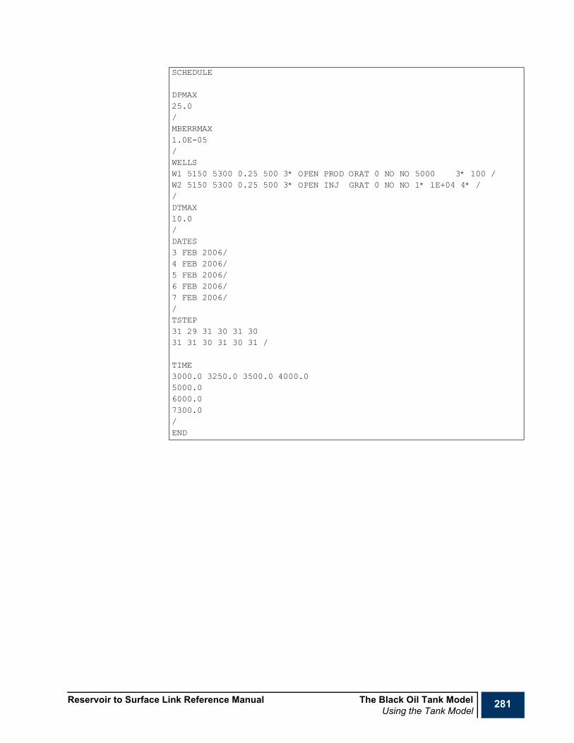
Reservoir to Surface Link Reference Manual The Black Oil Tank ModelUsing the Tank Model
281
SCHEDULE
DPMAX25.0/MBERRMAX1.0E-05/WELLSW1 5150 5300 0.25 500 3* OPEN PROD ORAT 0 NO NO 5000 3* 100 /W2 5150 5300 0.25 500 3* OPEN INJ GRAT 0 NO NO 1* 1E+04 4* //DTMAX10.0/DATES3 FEB 2006/4 FEB 2006/5 FEB 2006/6 FEB 2006/7 FEB 2006//TSTEP31 29 31 30 31 3031 31 30 31 30 31 /
TIME3000.0 3250.0 3500.0 4000.05000.06000.07300.0/END

282 The Black Oil Tank Model Reservoir to Surface Link Reference ManualAQUIFER
AQUIFER Aquifer propertiesThis keyword defines the properties of the analytical aquifer. This keyword should be followed by eleven items and terminated with a forward slash (/).
1 Aquifer type
• 0: None.
• 1: Fetkovich finite radial.
• 2: Fetkovich finite linear.
2 Aquifer length
• UNITS: m (METRIC), ft (FIELD)
• This is only required for the finite linear model and is ignored otherwise; for the radial type this may be defaulted by entering 1*.
3 Aquifer width
• UNITS: m (METRIC), ft (FIELD)
• This is only required for the finite linear model and is ignored otherwise; for the radial type this may be defaulted by entering 1*.
4 Aquifer radius
• UNITS: m (METRIC), ft (FIELD)
• This is only required for the finite radial model and is ignored otherwise; for the linear type this may be defaulted by entering 1*.
5 Aquifer encroachment angle
• UNITS: deg (METRIC), deg (FIELD)
• This is only required for the finite radial model and is ignored otherwise; for the linear type this may be defaulted by entering 1*.
6 Aquifer thickness
• UNITS: m (METRIC), ft (FIELD)
7 Aquifer rock compressibility
• UNITS: 1/bar (METRIC), 1/psi (FIELD)
8 Aquifer rock permeability
• UNITS: mD (METRIC), mD (FIELD)
9 Aquifer rock porosity
• UNITS: 1/bar (METRIC), 1/psi (FIELD)
10 Aquifer water compressibility
• UNITS: 1/bar (METRIC), 1/psi (FIELD)
11 Aquifer water viscosity
• UNITS: cP (METRIC), cP (FIELD)
RUNSPECx PROPS
SUMMARYSCHEDULE

Reservoir to Surface Link Reference Manual The Black Oil Tank ModelAQUIFER
283
Note With the exception of the caveats specific to items 2 to 5 inclusive, all items must be specified, if an aquifer type other than 0 is selected. An aquifer type of 0 may be specified in order to deselect the aquifer with the need to delete or comment out the keyword. By default, no aquifer is assumed to be present
Note If an aquifer is being modeled, the solution of the material balance becomes more complex and smaller time steps will typically be necessary to maintain convergence. In general, some experimentation will be necessary in order to achieve a suitable set of time steps. It is recommended that when aquifers are used, as an initial starting point, a maximum time step of one day should be specified using the DTMAX keyword together with a maximum material balance error of 0.01% using the MBERRMAX keyword. In addition, it may be necessary to constrain the maximum pressure change per time step using the DPMAX keyword.
Example-- Select finite linear aquiferAQUIFER4 1.0E+05 1.0E+04 1* 1* 1.0E+03 3.0E-03 10.00.3 4.0E-06 0.525/

284 The Black Oil Tank Model Reservoir to Surface Link Reference ManualBWREF
BWREF Reference water formation volume factorThis keyword specifies the water formation volume factor. This keyword should be followed by two items specifying the reference pressure and the water formation volume factor at this reference pressure and terminated with a forward slash (/).
1 Reference pressure (Pref)
• UNITS: barsa (METRIC), psia (FIELD)
2 Water formation volume factor at the reference pressure Bw(Pref)
• UNITS: rm3/sm3 (METRIC), rb/Mscf (FIELD)
The water formation volume factor at pressure P is calculated according to the expression:
Bw(P) = Bw(Pref) / (1 + X + (X2/2))
where:
X = Cw(P - Pref)
where Cw is the reservoir water compressibility specified using the keyword CW. If this keyword is not specified, the water formation volume factor defaults to a constant value of 1, which is independent of reservoir pressure. This keyword should not be specified if the PVT properties are specified via an input data table using the PVTTAB or the PVTTABDG keyword
Example
RUNSPECx PROPS
SUMMARYSCHEDULE
BWREF3000.0 1.02/

Reservoir to Surface Link Reference Manual The Black Oil Tank ModelCONTINIT
285
CONTINIT Initial phase contact depthsThis keyword specifies the initial phase contact depths. For LIVEOIL models, this keyword should be followed by two items specifying the gas-oil contact depth and the oil-water contact depth and terminated with a forward slash (/).
1 Gas-oil contact depth.
• UNITS: m (METRIC), ft (FIELD)
2 Oil-water contact depth.
• UNITS: m (METRIC), ft (FIELD)
For DRYGAS models, this keyword should be followed by one item specifying the gas-water contact depth and terminated with a forward slash (/).
1 Gas-water contact depth.
• UNITS: m (METRIC), ft (FIELD)
The contact depths should be within the depth extent of the reservoir, which is specified using either the RESCYL keyword or the RESVOL keyword. If there is no initial free gas, the gas-oil contact depth should be set equal to the top of the reservoir.
In order to calculate the initial conditions prior to the commencement of simulation, either the initial phase contacts should be specified using this keyword or the initial fluids in place should be specified using the FIPINIT keyword.
Example
RUNSPECx PROPS
SUMMARYSCHEDULE
-- Live oil model, gas-oil and oil-water contactsCONTINIT5100.0 5300.0/

286 The Black Oil Tank Model Reservoir to Surface Link Reference ManualCR
CR Reservoir rock compressibilityThis keyword defines the rock compressibility for the reservoir. This keyword should be followed by a single item and terminated with a forward slash (/).
1 Reservoir rock compressibility
• UNITS: 1/bars (METRIC), 1/psi (FIELD)
This keyword must be specified.
Example
RUNSPECx PROPS
SUMMARYSCHEDULE
CR3.0E-06/

Reservoir to Surface Link Reference Manual The Black Oil Tank ModelCW
287
CW Reservoir water compressibilityThis keyword defines the water compressibility for the reservoir. This keyword should be followed by a single item and terminated with a forward slash (/).
1 Reservoir water compressibility
• UNITS: 1/bars (METRIC), 1/psi (FIELD)
This keyword must be specified
Example
RUNSPECx PROPS
SUMMARYSCHEDULE
CW3.0E-06/
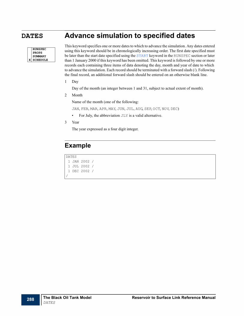
288 The Black Oil Tank Model Reservoir to Surface Link Reference ManualDATES
DATES Advance simulation to specified datesThis keyword specifies one or more dates to which to advance the simulation. Any dates entered using this keyword should be in chronologically increasing order. The first date specified must be later than the start date specified using the START keyword in the RUNSPEC section or later than 1 January 2000 if this keyword has been omitted. This keyword is followed by one or more records each containing three items of data denoting the day, month and year of date to which to advance the simulation. Each record should be terminated with a forward slash (/). Following the final record, an additional forward slash should be entered on an otherwise blank line.
1 Day
Day of the month (an integer between 1 and 31, subject to actual extent of month).
2 Month
Name of the month (one of the following:
JAN, FEB, MAR, APR, MAY, JUN, JUL, AUG, SEP, OCT, NOV, DEC)
• For July, the abbreviation JLY is a valid alternative.
3 Year
The year expressed as a four digit integer.
Example
RUNSPECPROPSSUMMARY
X SCHEDULE
DATES1 JAN 2002 /1 JUL 2002 /1 DEC 2002 //
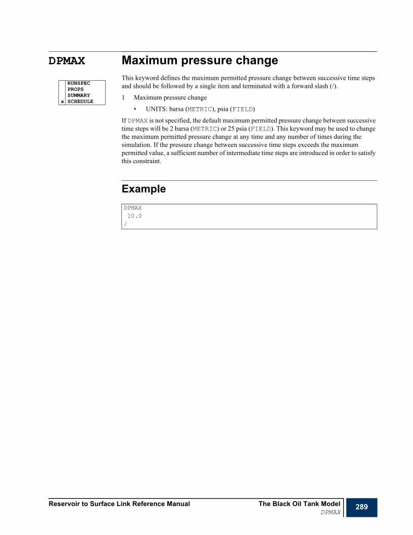
Reservoir to Surface Link Reference Manual The Black Oil Tank ModelDPMAX
289
DPMAX Maximum pressure changeThis keyword defines the maximum permitted pressure change between successive time steps and should be followed by a single item and terminated with a forward slash (/).
1 Maximum pressure change
• UNITS: barsa (METRIC), psia (FIELD)
If DPMAX is not specified, the default maximum permitted pressure change between successive time steps will be 2 barsa (METRIC) or 25 psia (FIELD). This keyword may be used to change the maximum permitted pressure change at any time and any number of times during the simulation. If the pressure change between successive time steps exceeds the maximum permitted value, a sufficient number of intermediate time steps are introduced in order to satisfy this constraint.
Example
RUNSPECPROPSSUMMARY
x SCHEDULE
DPMAX 10.0/

290 The Black Oil Tank Model Reservoir to Surface Link Reference ManualDRYGAS
DRYGAS Dry gas reservoirThis keyword specifies that the hydrocarbon constituent of the reservoir to be modeled consists of dry gas only. If neither DRYGAS nor LIVEOIL is specified, the reservoir model defaults to LIVEOIL, that is, the hydrocarbon constituents will be assumed to consist of live oil and optionally free gas.
Example
x RUNSPECPROPSSUMMARYSCHEDULE
-- Reservoir contains dry gasDRYGAS

Reservoir to Surface Link Reference Manual The Black Oil Tank ModelDTMAX
291
DTMAX Maximum time changeThis keyword defines the maximum permitted time interval between successive time steps and should be followed by a single item and terminated with a forward slash (/).
1 Maximum permitted time interval between time steps.
• UNITS: days (METRIC), days (FIELD)
If DTMAX is not specified, the default maximum permitted time interval between successive time steps will be 10 days. This keyword may be used to change the maximum permitted time interval at any time and any number of times during the simulation. The time interval between successive time steps may be smaller than the value specified by this keyword. This can occur if it is necessary to reduce the time step size to satisfy the maximum permitted pressure change. This may be defined by the keyword DPMAX. It may also occur is a report step occurs before the end to the DTMAX specified time period. Report steps are specified using the TIME or DATES keywords.
If an aquifer is being modeled, a maximum time step of 1 day is recommended as an initial starting point.
Example
RUNSPECPROPSSUMMARY
x SCHEDULE
DTMAX 5.0/

292 The Black Oil Tank Model Reservoir to Surface Link Reference ManualECHO
ECHO Switches echo output onThe keyword turns on the echoing of the contents of the input data file to the output print file. This echoing may be disabled subsequently using the NOECHO keyword, for example, when sections of the input data file are not required to be listed. These keywords may be specified any number of times in any section.
x RUNSPECx PROPSx SUMMARYx SCHEDULE

Reservoir to Surface Link Reference Manual The Black Oil Tank ModelEND
293
END Logical end of input fileThis keyword signifies the end of the input of data, and may occur anywhere in the input data file. If this keyword is omitted, one is generated at the end of the input data file. This keyword has no arguments and does not require a forward slash (/) as a terminator.
x RUNSPECx PROPSx SUMMARYx SCHEDULE

294 The Black Oil Tank Model Reservoir to Surface Link Reference ManualENDINC
ENDINC Logical end of include fileThis keyword terminates the input of data from an included file which has been specified using the INCLUDE keyword, there by returning control to the file in which this file has been included.
This keyword should not normally need to be entered because it is generated automatically at the end of the included file. It may, however, be used to terminate the reading of an included file before the actual end of file.
x RUNSPECx PROPSx SUMMARYx SCHEDULE

Reservoir to Surface Link Reference Manual The Black Oil Tank ModelFIELD
295
FIELD Field unitsThis keyword specifies that the input data to and the output data from the tank model are in Field units. This is the default units system for the tank model.This keyword has no associated data.
Example
x RUNSPECPROPSSUMMARYSCHEDULE
-- Input and output data are in Field unitsFIELD

296 The Black Oil Tank Model Reservoir to Surface Link Reference ManualFIPINIT
FIPINIT Initial fluids in placeThis keyword specifies the initial fluids in place. For LIVEOIL models, this keyword should be followed by two items specifying the initial free gas in place and the initial oil in place. It must be terminated with a forward slash (/).
1 Initial free gas in place.
• UNITS: sm3 (METRIC), Mscf (FIELD)
2 Initial oil in place.
• UNITS: sm3 (METRIC), stb (FIELD)
If there is no initial free gas, the value of the first item should be set to zero.
For DRYGAS models, this keyword should be followed by one item specifying the initial gas in place. It must be terminated with a forward slash (/).
1 Initial gas in place.
• UNITS: sm3 (METRIC), Mscf (FIELD)
In order to calculate the initial conditions prior to the commencement of simulation, either the initial fluids in place should be specified using this keyword or the initial phase contact depths should be specified using the CONTINIT keyword.
Example
RUNSPECx PROPS
SUMMARYSCHEDULE
-- Live oil model, no initial free gasFIPINIT0.0 1.0E+09/
Reservoir to Surface Link Reference Manual The Black Oil Tank ModelGASSG
297
GASSG Gas specific gravityThis keyword defines the gas specific gravity. This keyword should be followed by a single item and terminated with a forward slash (/).
1 Gas specific gravity (with reference to air)
If the PVT data are specified as an input data table using either the PVTTAB or the PVTTABDG keywords, this keyword should be omitted. If the PVT data are calculated from internal correlations and neither of these keywords are specified, the gas specific gravity defaults to a value of 0.7773
Example
RUNSPECx PROPS
SUMMARYSCHEDULE
GASSG0.75/

298 The Black Oil Tank Model Reservoir to Surface Link Reference ManualGFVFCORR
GFVFCORR Gas formation volume factor correlation methodThis keyword defines the gas formation volume factor correlation method. This keyword should be followed a single item consisting of an integer with the value of 1 and terminated with a forward slash (/).
1 Gas formation volume factor correlation method
• 1: Spivey and McCain method
If the PVT data are specified as an input data table using either the PVTTAB or the PVTTABDG keywords, this keyword should be omitted. If either of these keywords is not specified and the PVT data are obtained from internal correlations, the Spivey and McCain method is used.
Example
RUNSPECx PROPS
SUMMARYSCHEDULE
GFVFCORR1/

Reservoir to Surface Link Reference Manual The Black Oil Tank ModelINCLUDE
299
INCLUDE Include the contents of another named fileThe keyword should be followed by the name of a file from which input data are to be read. This file is opened and read to the end of the file unless an ENDINC keyword is encountered. The file is then closed and input resumed from the file containing the INCLUDE keyword, continuing from the next keyword. The file name may possess up to 132 characters and should be terminated by a forward slash (/) character. Nested include files are supported to an arbitrary depth but should not in general be necessary for the small amounts of data typically associated with the tank model.
ExampleThis example instructs the input data processing to suspend input from the current input data file, open the file FLUID1.INC, read this until either the end of the file or an ENDINC keyword is encountered and then return to the previous input data file and continue processing.
x RUNSPECx PROPSx SUMMARYx SCHEDULE
INCLUDEFLUID1.INC /

300 The Black Oil Tank Model Reservoir to Surface Link Reference ManualINITCOND
INITCOND Initial conditionsThis keyword specifies the initial conditions. For LIVEOIL models, this keyword should be followed by three items specifying the initial reservoir pressure, initial temperature and initial solution gas-oil ratio and terminated with a forward slash (/).
1 Initial reservoir pressure.
• UNITS: barsa (METRIC), psia (FIELD)
2 Initial reservoir temperature.
• UNITS: K (METRIC), R (FIELD)
3 Initial solution gas-oil ratio.
• UNITS: sm3/sm3 (METRIC), Mscf/stb (FIELD)
If the PVT data is being generated from correlations and there is an initial gas cap present, the reservoir oil will be saturated and the initial solution gas-oil ratio will be calculated from the PVT data. In this case,. item 3 above should not be specified. If, however, there is no initial gap cap present, the reservoir oil will be undersaturated and the third item must be specified.
For LIVEOIL models, the presence of an initial gas cap is signified by the values ascribed to the FIPINIT or the CONTINIT keywords. If the PVT data are not calculated internally but are instead specified using a user supplied input table via the PVTTAB keyword, the initial solution gas-oil ratio is obtained from this input table irrespective of whether the oil is initially saturated or under saturated and the third item on this keyword will be ignored.
In cases where the third item is not required but a data value has been supplied, this is ignored.
For DRYGAS models, this keyword should be followed by two items specifying the initial reservoir pressure and initial temperature and terminated with a forward slash (/).
1 Initial reservoir pressure.
• UNITS: barsa (METRIC), psia (FIELD)
2 Initial reservoir temperature.
• UNITS: K (METRIC), R (FIELD)
This keyword must be specified for all tank model simulations. The first and second items are always mandatory. The third item is mandatory for LIVEOIL models, where the PVT data are to be calculated internally.
Example
RUNSPECx PROPS
SUMMARYSCHEDULE
-- Live oil modelINITCOND200.0 300.0 295.0/

Reservoir to Surface Link Reference Manual The Black Oil Tank ModelLIVEOIL
301
LIVEOIL Live oil reservoirThis keyword specifies that the hydrocarbon constituents of the reservoir to be modeled consist of live oil and optionally free gas. If neither DRYGAS nor LIVEOIL is specified, the reservoir model defaults to LIVEOIL.
Example
x RUNSPECPROPSSUMMARYSCHEDULE
-- Reservoir contains free gas and live oilLIVEOIL
302 The Black Oil Tank Model Reservoir to Surface Link Reference ManualMBALDAKE
MBALDAKE Dake material balance methodThis keyword specifies that the material balance calculation method to be used is based upon that due to L P Dake.
The MBALDAKE method is the only method available for DRYGAS models. For LIVEOIL models, either the MBALDAKE or the MBALFPT material balance method may be selected.
If neither the MBALDAKE nor the MBALFPT keyword is specified, the MBALFPT method will be used for LIVEOIL models and the MBALDAKE method will be used for DRYGAS models.
Example
RUNSPECPROPSSUMMARY
x SCHEDULE
-- Select Dake’s material balance calculation methodMBALDAKE

Reservoir to Surface Link Reference Manual The Black Oil Tank ModelMBALFPT
303
MBALFPT FPT material balance methodThis keyword specifies that the material balance calculation method for LIVEOIL models is to be based upon that employed by the FPT (Field Planning Tool) software package.
For LIVEOIL models, either the MBALDAKE or the MBALFPT material balance method may be selected. The MBALDAKE method is the only method available for DRYGAS models.
If neither the MBALDAKE nor the MBALFPT keyword is specified, the MBALFPT method will be used for LIVEOIL models and the MBALDAKE method will be used for MBALFPT models.
Example
x RUNSPECPROPSSUMMARYSCHEDULE
-- Select FPT material balance calculation methodMBALFPT

304 The Black Oil Tank Model Reservoir to Surface Link Reference ManualMBERRMAX
MBERRMAX Maximum material balance errorThis keyword defines the maximum permitted material balance error when solving the material balance equation for reservoir pressure at a given point in time taking into account net reservoir fluid production and injection up to this time. This keyword should be followed by a single item and terminated with a forward slash (/).
1 Maximum permitted material balance error.
• UNITS: percent (%)
If this keyword is not specified, the maximum permitted error defaults to 1.0E-05. This keyword may be used to change this value at any time and any number of times during the simulation. The number of iterations and hence the computation time per time step will increase as the maximum material balance error permitted is reduced.
For models involving aquifers, an increased value of maximum material balance error may be necessary and a value of 0.01% is recommended as an initial starting point.
Example
RUNSPECPROPSSUMMARY
x SCHEDULE
MBERRMAX 1.0E-04/

Reservoir to Surface Link Reference Manual The Black Oil Tank ModelMETRIC
305
METRIC Metric unitsThis keyword specifies that the input data to and the output data from the tank model are in metric units. This default units system for the tank model is field. This keyword has no associated data and should be specified if metric units are required.
Example
x RUNSPECPROPSSUMMARYSCHEDULE
-- Input and output data are in Metric unitsMETRIC

306 The Black Oil Tank Model Reservoir to Surface Link Reference ManualNOECHO
NOECHO Disable echoing of the input fileThe keyword disables the echoing to the output print file of the input data which are read from the input data file. The echoing of input data may be enabled using the ECHO keyword. This keyword has no associated input data and does not require a forward slash (/) terminator.
x RUNSPECx PROPSx SUMMARYx SCHEDULE
Reservoir to Surface Link Reference Manual The Black Oil Tank ModelNTG
307
NTG Reservoir net to gross thickness ratioThis keyword defines the reservoir net to gross thickness ratio and should be followed by a single item and terminated with a forward slash (/).
1 Reservoir net to gross thickness ratio
• UNITS: fraction (METRIC), fraction (FIELD)
If this keyword is not specified the net to gross ratio will default to unity.
Example
RUNSPECx PROPS
SUMMARYSCHEDULE
NTG0.8/

308 The Black Oil Tank Model Reservoir to Surface Link Reference ManualOILAPI
OILAPI Oil APIThis keyword defines the oil API. This keyword is only required for LIVEOIL models and should be followed by a single item and terminated with a forward slash (/).
1 Oil API
If the PVT data is specified as an input data table using the PVTTAB keyword, this keyword should be omitted. If the PVT data are calculated from internal correlations and this keyword is not specified, the oil API defaults to a value of 45.5.
Example
RUNSPECx PROPS
SUMMARYSCHEDULE
OILAPI0.8/
Reservoir to Surface Link Reference Manual The Black Oil Tank ModelOFVFCORR
309
OFVFCORR Oil formation volume factor correlation methodThis keyword defines the oil formation volume factor correlation method. This keyword is only required for LIVEOIL models and should be followed by a single item consisting of an integer with the value of either 1 or 2 and terminated with a forward slash (/).
1 Oil formation volume factor correlation method
• 1: Standing
• 2: Vasquez
If the PVT data is specified as an input data table using the PVTTAB keyword, this keyword should be omitted. If this keyword is not specified and the PVT data are calculated from internal correlations, the Standing method is used.
Example
RUNSPECx PROPS
SUMMARYSCHEDULE
OFVFCORR1/

310 The Black Oil Tank Model Reservoir to Surface Link Reference ManualPBRSCORR
PBRSCORR Bubble point pressure and solution gas-oil ratio correlation methodThis keyword defines the bubble point pressure and solution gas-oil ratio correlation method. This keyword is only required for LIVEOIL models and should be followed a single item consisting of an integer with the value in the range of 1 to 6 inclusive and terminated with a forward slash (/).
1 Bubble point pressure and solution gas-oil ratio correlation method
• 1: Standing
• 2: Lasater
• 3: Vasquez
• 4: Petrosky and Farshad
• 5: Velarde, Blasingname and McCain
• 6: Kartoatmodjo and Schmidter
If the PVT is specified as an input data table using the PVTTAB keyword, this keyword should be omitted. If this keyword is not specified and the PVT data are calculated from internal correlations, the Standing method is used.
Example
RUNSPECx PROPS
SUMMARYSCHEDULE
PBRSFCORR2/

Reservoir to Surface Link Reference Manual The Black Oil Tank ModelPERM
311
PERM Reservoir permeabilityThis keyword defines the permeability for the reservoir. This keyword should be followed by a single item and terminated with a forward slash (/).
1 Reservoir permeability
• UNITS: mD (METRIC), mD (FIELD)
This keyword must be specified.
Example
RUNSPECx PROPS
SUMMARYSCHEDULE
PERM15.0/
312 The Black Oil Tank Model Reservoir to Surface Link Reference ManualPORO
PORO Reservoir porosityThis keyword defines the porosity for the reservoir. This keyword should be followed by a single item and terminated with a forward slash (/).
1 Reservoir rock porosity
• UNITS: fraction (METRIC), fraction (FIELD)
This keyword must be specified.
Example
RUNSPECx PROPS
SUMMARYSCHEDULE
PORO0.3/

Reservoir to Surface Link Reference Manual The Black Oil Tank ModelPVTTAB
313
PVTTAB PVT tabular dataThis keyword specifies the fluid PVT properties in terms of an input data table. It provides an alternative to using internal PVT correlations for constructing the fluid properties. This keyword consists of a set of data records each of which contains the following nine data items.
1 Pressure.
• UNITS: barsa (METRIC), psia (FIELD)
2 Solution gas-oil ratio (Rs).
• UNITS: sm3/sm3 (METRIC), Mscf/stb (FIELD)
3 Oil formation volume factor (Bo).
• UNITS: rm3/sm3 (METRIC), rb/stb (FIELD)
4 Gas formation volume factor (Bg).
• UNITS: rm3/sm3 (METRIC), rb/Mscf (FIELD)
5 Gas Z-factor.
6 Water formation volume factor (Bw).
• UNITS: sm3/sm3 (METRIC), rb/stb (FIELD)
7 Oil viscosity (μo)
• UNITS: cP (METRIC), cP (FIELD)
8 Gas viscosity (μg)
• UNITS: cP (METRIC), cP (FIELD)
9 Water viscosity (μw)
• UNITS: cP (METRIC), cP (FIELD)
Each record must be terminated with a forward slash (/). Following the final record, an additional forward slash must be entered.
The table should contain sufficient rows to realistically represent the PVT fluid properties. With the exception of the first and last rows, any data item in columns two to eight inclusive may be defaulted whereupon the missing values are assigned from linear interpolations about the nearest columnar neighbors.
This keyword is intended primarily for use with LIVEOIL models but may also be used with DRYGAS models, in which case the contents of columns 2, 3 and 7 will be ignored and may be defaulted. For DRYGAS models, the reduced table PVTTABDG may also be used.
If this keyword is used, the alternative keywords that are used to control the construction of the internal PVT data from correlations, specifically BWREF, GASSG, GFVFCORR, OILAPI, OFVFCORR, PBRSCORR and ZFACCORR should be omitted.
The range of data entered in this table should be consistent with the range of PVT conditions to be simulated. In particular, if the oil is initially undersaturated, the table should include an undersaturated region of pressure extent consistent with the initial reservoir pressure and the extent of the anticipated pressure variation. If the oil subsequently becomes undersaturated at a pressure that is above the initial bubble point pressure, the simulation is abandoned. If, however, the oil becomes undersaturated at a pressure that is lower than the original bubble point pressure the input data in this table is scaled appropriately.
RUNSPECx PROPS
SUMMARYSCHEDULE

314 The Black Oil Tank Model Reservoir to Surface Link Reference ManualPVTTAB
If the PVT data is derived from internal correlations, the PVT data is automatically recalculated whenever the oil changes from saturated to undersaturated conditions and whenever the oil remains saturated at the previous bubble point pressure as the reservoir pressure increases.
ExamplePVTTAB-- P Rs y Bo Bg Zfac Bw Voil Vgas Vwat14.5 0.0017 1.0671 227.988 0.9984 1.0347 0.9670 0.0108 0.2875 /100.0 0.0178 1.0740 32.7639 0.9895 1.0343 0.9406 0.0110 0.2885 /200.0 0.0410 1.0842 16.2131 0.9793 1.0339 0.6192 0.0113 0.2897 /300.0 0.0668 1.0956 10.6987 0.9694 1.0335 0.5751 0.0115 0.2909 /500.0 0.1236 1.1215 6.29231 0.9502 1.0327 0.5055 0.0120 0.2934 /750.0 0.2014 1.1582 4.09641 0.9279 1.0316 0.4429 0.0127 0.2965 /1000.0 0.2848 1.1989 3.00577 0.9078 1.0306 0.3973 0.0134 0.2998 /1500.0 0.4641 1.2907 1.93347 0.8759 1.0286 0.3346 0.0148 0.3067 /2000.0 0.6563 1.3943 1.41988 0.8577 1.0265 0.2929 0.0163 0.3141 /2500.0 0.8586 1.5081 1.13184 0.8546 1.0244 0.2628 0.0178 0.3219 /3000.0 1.0694 1.6313 0.95554 0.8658 1.0224 0.2398 0.0194 0.3302 /3130.7 1.1252 1.6646 0.92087 0.8707 1.0219 0.2347 0.0198 0.3324 /3500.0 1.1252 1.6518 0.84051 0.8885 1.0204 0.2431 0.0210 0.3389 //
Reservoir to Surface Link Reference Manual The Black Oil Tank ModelPVTTABDG
315
PVTTABDG PVT gas-water tabular dataThis keyword specifies the fluid PVT properties for DRYGAS models in terms of an input data table. It provides an alternative to using internal PVT correlations for constructing the fluid properties. This keyword consists of a set of data records each of which contains the following six data items.
1 Pressure.
• UNITS: barsa (METRIC), psia (FIELD)
2 Gas formation volume factor (Bg).
• UNITS: rm3/sm3 (METRIC), rb/Mscf (FIELD)
3 Gas Z-factor.
4 Water formation volume factor (Bw).
• UNITS: sm3/sm3 (METRIC), rb/stb (FIELD)
5 Gas viscosity (μg)
• UNITS: cP (METRIC), cP (FIELD)
6 Water viscosity (μw)
• UNITS: cP (METRIC), cP (FIELD)
Each record must be terminated with a forward slash (/). Following the final record, an additional forward slash must be entered.
The table should contain sufficient rows to realistically represent the PVT fluid properties. With the exception of the first and last rows, any data item in columns two to eight inclusive may be defaulted whereupon the missing values are assigned from linear interpolations about the nearest columnar neighbors.
If this keyword is used, the alternative keywords that are used to control the construction of the internal PVT data from correlations, specifically BWREF, GASSG, GFVFCORR and ZFACCORR should be omitted.
The range of data entered in this table should be consistent with the range of PVT conditions to be simulated.
RUNSPECx PROPS
SUMMARYSCHEDULE

316 The Black Oil Tank Model Reservoir to Surface Link Reference ManualPVTTABDG
Example
PVTTABDG-- P Bg Zfac Bw Vgas Vwat14.5 227.988 0.9984 1.0347 0.0108 0.2875 /100.0 32.7639 0.9895 1.0343 0.0110 0.2885 /200.0 16.2131 0.9793 1.0339 0.0113 0.2897 /300.0 10.6987 0.9694 1.0335 0.0115 0.2909 /500.0 6.29231 0.9502 1.0327 0.0120 0.2934 /750.0 4.09641 0.9279 1.0316 0.0127 0.2965 /1000.0 3.00577 0.9078 1.0306 0.0134 0.2998 /1500.0 1.93347 0.8759 1.0286 0.0148 0.3067 /2000.0 1.41988 0.8577 1.0265 0.0163 0.3141 /2500.0 1.13184 0.8546 1.0244 0.0178 0.3219 /3000.0 0.95554 0.8658 1.0224 0.0194 0.3302 /3130.7 0.92087 0.8707 1.0219 0.0198 0.3324 /3500.0 0.84051 0.8885 1.0204 0.0210 0.3389 //

Reservoir to Surface Link Reference Manual The Black Oil Tank ModelPVTINT
317
PVTINT PVT internal correlation pressure controlsThis keyword specifies the properties of the PVT table constructed from the internal PVT correlations. This keyword should be followed by two items specifying the table pressure step size and the maximum pressure and terminated with a forward slash (/).
1 Internal PVT table pressure step size.
• UNITS: barsa (METRIC), psia (FIELD)
2 Internal PVT table maximum pressure.
• UNITS: barsa (METRIC), psia (FIELD)
If this keyword is not specified or if these values are defaulted, the internal pressure step size is set to 5 barsa (METRIC) or 100 psia (FIELD) and the maximum table pressure is set to 60 barsa (METRIC) or 1000 psia (FIELD) above the initial reservoir pressure. The internally calculated PVT table is listed in the print file and may be inspected and adjusted as required. If the solution of the material balance equation requires PVT calculations at pressures that are higher than the extent of the internally constructed PVT table, an error occurs and the simulation fails. Irrespective of the values of these parameters the first pressure value in the table is 1 barsa (METRIC) or 14.5 psia (FIELD). If the PVT data are specified as an input data table using the PVTTAB or the PVTTABDG keyword, this keyword should be omitted.
Example
RUNSPECx PROPS
SUMMARYSCHEDULE
PVTINT10.0 50.0 /

318 The Black Oil Tank Model Reservoir to Surface Link Reference ManualREPORT
REPORT Report optionsThis keyword defines the various reporting options. This keyword should be followed by one or more mnemonics selected from the following and terminated by a forward slash (/).
ALL Select all reporting options.
NONE Deselect all reporting options.
WELLS Report time step well summary details.
TIMESTEP Report time step field summary details.
OFFICEOBS Output ECLIPSE Office observed data files.
By default only the time step summary details are selected. If ECLIPSE Office observed data files are selected, a file is created of the form input_Field.obs together with a series of files of the form input_wellname.obs with a separate file corresponding to each well name specified in the tank model. These files are column ordered tabular data files, which may be imported into a spreadsheet or directly into ECLIPSE Office as observable data. All summary vectors created by the tank model for both the field as a single group and the individual wells are exported to these files.
Example
RUNSPECPROPS
x SUMMARYSCHEDULE
REPORTWELLS TIMSETEP OFFICEOBS/

Reservoir to Surface Link Reference Manual The Black Oil Tank ModelRESCYL
319
RESCYL Cylindrical reservoir geometryThis keyword specifies the geometry of the reservoir in terms of a simple cylinder and should be followed by three items specifying the top depth, bottom depth and radius of the cylinder and terminated by a forward slash (/).
1 Top depth.
• UNITS: m (METRIC), ft (FIELD)
2 Bottom depth.
• UNITS: m (METRIC), ft (FIELD)
3 Radius
• UNITS: m (METRIC), ft (FIELD)
Either this keyword or the RESVOL keyword should be used to specify the geometry of the reservoir.
Example
RUNSPECx PROPS
SUMMARYSCHEDULE
RESCYL5000.0 5500.0 3000.0 /

320 The Black Oil Tank Model Reservoir to Surface Link Reference ManualRESVOL
RESVOL Reservoir area versus depthThis keyword specifies the geometry of the reservoir in terms of a table of depth versus area, hence permitting a more complex shape to be defined than that of a simple cylinder. The table should consist of two or more records with each one consisting of the following two items.
1 Depth.
• UNITS: m (METRIC), ft (FIELD)
2 Area.
• UNITS: m2 (METRIC), ft2 (FIELD)
Each record should be terminate by a forward slash (/) and the final record should be terminated by an additional forward slash on an otherwise blank line. Either this keyword or the RESCYL keyword should be used to specify the geometry of the reservoir.
Example
RUNSPECx PROPS
SUMMARYSCHEDULE
RESVOL5000.0 3000.0 /5200.0 3100.0 /5300.0 3200.0 //

Reservoir to Surface Link Reference Manual The Black Oil Tank ModelSGRW
321
SGRW Reservoir residual gas saturation to waterThis keyword defines the reservoir residual gas saturation to water. This keyword should be followed by a single item and terminated with a forward slash (/).
1 Reservoir residual gas saturation to water (Sgrw)
• UNITS: fraction (METRIC), fraction (FIELD)
This keyword is only required for DRYGAS models. If this keyword is not specified, this value will default to zero.
Example
RUNSPECx PROPS
SUMMARYSCHEDULE
SGRW0.01/

322 The Black Oil Tank Model Reservoir to Surface Link Reference ManualSORG
SORG Reservoir residual oil saturation to gasThis keyword defines the reservoir residual oil saturation to gas. This keyword should be followed by a single item and terminated with a forward slash (/).
1 Reservoir residual oil saturation to gas (Sorg)
• UNITS: fraction (METRIC), fraction (FIELD)
This keyword is only required for LIVEOIL models. If this keyword is not specified, this value will default to zero.
Example
RUNSPECx PROPS
SUMMARYSCHEDULE
SORG0.01/
Reservoir to Surface Link Reference Manual The Black Oil Tank ModelSORW
323
SORW Reservoir residual oil saturation to waterThis keyword defines the reservoir residual oil saturation to water. This keyword should be followed by a single item and terminated with a forward slash (/).
1 Reservoir residual oil saturation to water (Sorw)
• UNITS: fraction (METRIC), fraction (FIELD)
This keyword is only required for LIVEOIL models. If this keyword is not specified, this value defaults to zero.
Example
RUNSPECx PROPS
SUMMARYSCHEDULE
SORW0.01/

324 The Black Oil Tank Model Reservoir to Surface Link Reference ManualSTART
START Simulation start dateThis keyword specifies the start date of the simulation. Any report dates entered via the DATES keyword in the SCHEDULE section must be later than the start date. This keyword is followed by three items of data denoting the day, month and year of the start of the simulation terminated with a forward slash (/).
1 Day
Day of the month (an integer between 1 and 31)
2 Month
Name of the month (one of the following: JAN, FEB, MAR, APR, MAY, JUN, JUL, AUG, SEP, OCT, NOV, DEC)
• For July, the abbreviation JLY is a valid alternative.
3 Year
The year expressed as a four digit integer.
If this keyword is omitted the start date defaults to 1 January 2000.
Example
RUNSPECPROPSSUMMARY
X SCHEDULE
-- Start date for simulationSTART1 JAN 2001/

Reservoir to Surface Link Reference Manual The Black Oil Tank ModelSWC
325
SWC Reservoir connate water saturationThis keyword defines the reservoir connate water saturation. This keyword should be followed by a single item and terminated with a forward slash (/).
1 Reservoir connate water saturation (Swc).
• UNITS: fraction (METRIC), fraction (FIELD)
This keyword must be specified.
Example
RUNSPECx PROPS
SUMMARYSCHEDULE
SWC0.2/

326 The Black Oil Tank Model Reservoir to Surface Link Reference ManualTIME
TIME Advance simulation to specified timesThis keyword specifies one or more times to which to advance the simulation. Any times entered using this keyword should be specified in increasing order and should be consistent with the current simulation time at the point at which they are specified. This keyword is followed by one or more items each specifying a time in days to which to advance the simulation. The record should be terminated with a forward slash (/).
Example
RUNSPECPROPSSUMMARY
X SCHEDULE
TIME365.0 730.0 1460.0/

Reservoir to Surface Link Reference Manual The Black Oil Tank ModelTITLE
327
TITLE Simulation titleThis keyword specifies the optional simulation title. This keyword specifies that the line of text that follows the keyword is to be used as the simulation title. This keyword may be specified in both the RUNSPEC and in SCHEDULE sections in order to change the title as a function of simulation time. This title is output at the start of simulation and as part of the reporting information which is written to the print file.
It should be noted that this keyword does not require a forward slash (/) terminator.
Example
X RUNSPECPROPSSUMMARY
X SCHEDULE
TITLETest Example Five

328 The Black Oil Tank Model Reservoir to Surface Link Reference ManualTSTEP
TSTEP Advance simulation by specified time stepst This keyword specifies one or more time steps by which to advance the simulation. This
keyword is followed by one or more items each specifying a timestep in days by which to advance the simulation. The record should be terminated with a forward slash (/).
Example
RUNSPECPROPSSUMMARY
X SCHEDULE
TSTEP31 28 31 30 31 30 31 31 30 31 30 31/

Reservoir to Surface Link Reference Manual The Black Oil Tank ModelWELLS
329
WELLS Well dataThis keyword specifies the well data in terms of one or more records each containing twenty items of data which are described below.
1 Well name.
Character string of up to eight characters with no embedded spaces.
Wild cards may be used to specify a subset of wells. For example, a single asterisk character (*) signifies all wells whereas a string such as W* signifies all well names commencing with the character W. You must specify this item as there is no default.
2 Completion start depth. You must specify this item as there is no default.
• UNITS: m (METRIC), ft (FIELD)
This should lie within the depth extent of the reservoir and be less than the completion stop depth
3 Completion end depth. You must specify this item as there is no default.
• UNITS: m (METRIC), ft (FIELD)
This should lie within the depth extent of the reservoir and be greater than the completion start depth
4 Well bore radius.
• UNITS: m (METRIC), ft (FIELD)
• DEFAULT: 0.25 ft
5 Well drainage radius. You must specify this item as there is no default.
• UNITS: m (METRIC), ft (FIELD)
6 Well skin factor
• This value defaults to zero if unspecified.
• DEFAULT: 0
7 For LIVEOIL models, this item defines the gas coning height
• UNITS: m (METRIC), ft (FIELD)
• DEFAULT: 0
This provides a simple mechanism for adjusting the effective gas-oil contact depth in the proximity of the well. The actual contact depth is increased, that is, the contact is lowered, by the addition of the specified value of the gas coning height. For DRYGAS models, this item is ignored
8 Water coning height
• UNITS: m (METRIC), ft (FIELD)
• DEFAULT: 0
This provides a simple mechanism for adjusting the effective oil-water contact depth in the proximity of the well. The actual contact depth is reduced, that is, the contact is raised, by the subtraction of the specified value of the water coning height.
9 Well status.
This may be either OPEN or SHUT. The shortest unique string will suffice.
DEFAULT: SHUT
RUNSPECPROPSSUMMARY
x SCHEDULE

330 The Black Oil Tank Model Reservoir to Surface Link Reference ManualWELLS
10 Well type. You must specify this item as there is no default.
This may be either PROD or INJ corresponding to producer or injector respectively. The shortest unique string suffices.
11 Well control mode. This item must be specified.
For LIVEOIL model producers, this may be one of:
• ORAT: Surface oil rate control.
• GRAT: Surface gas rate control
• WRAT: Surface water rate control
• LRAT: Surface liquid rate control
• VRAT: Reservoir volume rate control.
• BHP: Bottom hole pressure control
For LIVEOIL model injectors, this may be one of:
• GRAT: Gas injector under surface gas rate control
• WRAT: Water injector under surface water rate control
• GBHP: Gas injector under bottom hole pressure control
• WBHP: Water injector under bottom hole pressure control
For DRYGAS model producers, this may be one of:
• GRAT: Surface gas rate control
• WRAT: Surface water rate control
• LRAT: Surface liquid rate control
• VRAT: Reservoir volume rate control.
• BHP: Bottom hole pressure control
For DRYGAS model injectors, this may be one of:
• GRAT: Gas injector under surface gas rate control
• WRAT: Water injector under surface water rate control
• GBHP: Gas injector under bottom hole pressure control
• WBHP: Water injector under bottom hole pressure control
When specifying these targets and limits the shortest unique string suffices.
12 Down time fraction.
This specifies the proportion of the time for which the well is non-operational and defaults to zero; that is, by default the well is assumed to be fully operational during the period of time to which this keyword applies.
• DEFAULT: 0
13 Shut upon gas-oil contact reaching completions (LIVEOIL models) or gas-water contact reaching completions (DRYGAS models).
This may be either YES or NO and, if set to YES, causes the well to be shut when the contact including any coning height offset reaches the well completion start depth. By default the well is not shut. The shortest unique string suffices.
14 Shut upon oil-water contact reaching completions (LIVEOIL models). For models this item is ignored.
Reservoir to Surface Link Reference Manual The Black Oil Tank ModelWELLS
331
This may be either YES or NO and, if set to YES, causes the well to be shut when the contact including any coning height offset reaches the well completion stop depth. By default the well is not shut. The shortest unique string suffices.
15 Oil rate target or limit (LIVEOIL models)
• UNITS: sm3/day (METRIC), stb/day (FIELD)
• DEFAULT: 1E+20
For a producer this specifies the surface oil rate production target if the well is under oil rate control, otherwise this represents the surface oil rate limit. For DRYGAS models, this item is ignored.
Note For gas and water injectors this item is ignored.
• The default value is zero.
16 Gas rate target or limit
• UNITS: sm3/day (METRIC), Mscf/day (FIELD)
• DEFAULT: 1E+20 for a producer or 0 for a gas injector.
For a producer this specifies the surface gas rate production target if the well is under gas rate control, otherwise this represents the surface gas rate limit.
For a gas injector this specifies the surface gas rate injection target if the well is under surface gas rate control or the surface gas rate limit if the well is under BHP control.
Note For oil and water injectors this item is ignored.
17 Water rate target or limit
• UNITS: sm3/day (METRIC), stb/day (FIELD)
• DEFAULT: 1E+20 for a producer and 0 for a water injector.
For a producer this specifies the surface water rate production target if the well is under water rate control, otherwise this represents the surface water rate limit.
For a water injector this specifies the surface water rate injection target if the well is under surface water rate control or the surface water rate limit if the well is under BHP control.
Note For oil and gas injectors this item is ignored.
18 Liquid rate target or limit
• UNITS: sm3/day (METRIC), stb/day (FIELD)
• DEFAULT: 1E+20
For a producer this specifies the surface liquid rate production target if the well is under liquid rate control, otherwise this represents the surface liquid rate limit.
Note For an injector this item is ignored.

332 The Black Oil Tank Model Reservoir to Surface Link Reference ManualWELLS
19 Volume rate target or limit
• UNITS: rm3/day (METRIC), rb/day (FIELD)
• DEFAULT: 1E+20
For a producer this specifies the reservoir volume production target if the well is under volume rate control, otherwise this represents the reservoir volume rate limit.
Note For an injector this item is ignored.
20 BHP target or limit.
• UNITS: barsa (METRIC), psia (FIELD)
• DEFAULT: 1 barsa (METRIC) or 14.5 psia (FIELD) for a producer, or 1000 barsa (METRIC) or 15000 psia (FIELD) for an injector.
For a producer this specifies the bottom hole pressure target if the well is under bottom hole pressure control, otherwise this represents the bottom hole pressure lower limit.
For an injector this represents the bottom hole pressure target if the well is under bottom hole pressure control, otherwise this represents the bottom hole pressure upper limit.
Note When calculating the well performance, the well productivity or injectivity index is used to determine the bottom hole pressure and hence whether the well can achieve the specified target. In some cases this results in a reduced target rate to that specified. In addition, the target rate may be reduced to satisfy constraints imposed by other limits. Ultimately the rate is determined by the most constraining limit.
Each record should be terminated by a forward slash (/). Following the final record, an additional forward slash should be entered on an otherwise blank line. With the exception of the well name, which may include wild cards, any item may be omitted by specifying 1* instead of the value, or by specifying n* when defining n contiguous omissions. When a value is omitted in this manner, the previously defined value is used. However, not all items involve implicit default values. The initial definition for any well, therefore, must contain a consistent and sufficient set of values if items are to be omitted subsequently.
ExampleWELLSW1 5150 5300 0.25 500 3* OPEN PROD ORAT 0 NO NO 5000 3* 100 /W2 5150 5300 0.25 500 3* OPEN INJ GRAT 0 NO NO * 1E+04 4* //
Reservoir to Surface Link Reference Manual The Black Oil Tank ModelZFACCORR
333
ZFACCORR Gas Z-factor correlation methodThis keyword defines the gas Z-factor correlation method. This keyword should be followed a single item consisting of an integer with the value in the range of 1 to 3 inclusive and terminated with a forward slash (/).
1 Z-factor correlation method
• 1: Hall and Yarborough
• 2: Dranchuk and Abou-Kassem
• 3: Standing
If the PVT data is specified as an input data table using the PVTTAB or the PVTTABDG keywords, this keyword should be omitted. If this keyword is not specified and the PVT data are calculated from internal correlations, the Hall and Yarborough method is used.
Example
RUNSPECx PROPS
SUMMARYSCHEDULE
ZFACCORR1/

334 The Black Oil Tank Model Reservoir to Surface Link Reference ManualZFACCORR

Reservoir to Surface Link Reference Manual Limitations and restrictionsIntroduction
335
Chapter 8Limitations and restrictions
IntroductionThis chapter details the limitations and restrictions in this release. It contains information on restrictions for:
• "ECLIPSE special options" on page 336
• "Cross-platform runs" on page 336.
• "Keyword specific restrictions" on page 336.
It also contains information on the following limitations in this release.
• "ECLIPSE 300 tasks" on page 339
• "PIPESIM tasks" on page 339
• "Global group control" on page 339
• "GAP tasks" on page 339

336 Limitations and restrictions Reservoir to Surface Link Reference ManualCurrent restrictions
Current restrictions
ECLIPSE special options• Some of the ECLIPSE special options cannot be used when ECLIPSE is controlled by
R2SL. Incompatible options include:
• Gas field operations.
R2SL does not allow the automatic calculation of DCQ, (keyword GASYEAR or GASPERIO) which requires the simulation to jump back to the start of the contract period.
• Gas lift optimization.
This cannot be integrated with an external network model or across coupled reservoirs.
Cross-platform runs• Mixed Windows/Linux configurations are not supported as MPIPro will not allow cross-
platform communication. PIPESIM/ECLIPSE coupling may be performed on Linux or Windows but not on a mixture of the two. GAP coupling will only run on Windows, so it may not currently be coupled to a simulation running on Linux.
Keyword specific restrictions
NSINKBOThe following restrictions apply to keyword NSINKBO in the current release
• when modifying conditions of a terminal node in a production network, only the option PRES can be used in item 3 of the keyword.
Note R2SL ignores the already set rate in a sink node of a black oil injection network when this node does not map to a reservoir boundary node (independent sink node). Rate at an independent sink node should be set from R2SL using keyword NSINKBO. If the rate at this node is not set from R2SL, its corresponding branch is disabled.
NSINKCOThe following restrictions apply to keyword NSINKCO in the current release:
• when setting or modifying conditions at a sink node belonging to an injection network, only the option RATE can be used in item 2 of the keyword.
• when modifying conditions of a terminal node in a production network, only the option PRES can be used in item 2 of the keyword.
Reservoir to Surface Link Reference Manual Limitations and restrictionsCurrent restrictions
337
Note R2SL ignores the rate already set in a sink node of a compositional injection network when this node does not map to a reservoir boundary node (independent sink node). The rate at an independent sink node should be set from R2SL using NSINKCO. If the rate at this node is not set from R2SL, its corresponding branch is disabled.
NSOURCBOThe following restrictions apply to keyword in the current release:
• when modifying conditions of a terminal node in an injection network, only the option PRES can be used in item 2 of the keyword.
Note R2SL ignores the already set rate in a source node of a black oil production network when this node does not map to a reservoir boundary node (independent source node). The rate at an independent source node should be set from R2SL using keyword NSOURCBO. If the rate at this node is not set from R2SL, its corresponding branch is disabled.
NSOURCCOThe following restrictions apply in the current release:
• when setting or modifying conditions at a sink node belonging to an injection network, only the option RATE can be used in item 2 of the keyword.
• when modifying conditions of a terminal node in a production network, only the option PRES can be used in item 2 of the keyword.
Note R2SL ignores the already set rate in a source node of a compositional production network when this node does not map to a reservoir boundary node (independent source node). The rate at an independent source node should be set from R2SL using NSOURCCO. If the rate at this node is not set from R2SL, its corresponding branch is disabled.
WCONINJE• The well, as well as its completions, should be specified in the reservoir model (using
WELSPECS and COMPDAT in an ECLIPSE model). The well should also be opened. The control data for the well should also be defaulted in the reservoir model (using WCONINJE in an ECLIPSE model).
WCONPROD• The well, as well as its completions, should be specified in the reservoir model (using
WELSPECS and COMPDAT in an ECLIPSE model). The well should also be opened. The control data for the well should also be defaulted in the reservoir model (using WCONPROD in an ECLIPSE model).

338 Limitations and restrictions Reservoir to Surface Link Reference ManualCurrent restrictions
WELOPEN• The well, as well as its completions, should be specified in the reservoir model (using
WELSPECS and COMPDAT in an ECLIPSE model). The well should also be opened. The control data for the well should also be defaulted in the reservoir model (using WCONPROD or WCONINJE in an ECLIPSE model).

Reservoir to Surface Link Reference Manual Limitations and restrictionsCurrent limitations
339
Current limitations
ECLIPSE 300 tasks• In the case of a reservoir task, the FIELD group, as well as all node groups, cannot contain
wells.
PIPESIM tasks • Mixing production and injection wells in the same network model is not permitted.
Separate production and injection network models should be defined.
• Pumps and compressors may not be defined with user curves.
• Multiport gaslift valves may not be used with the NETGLIFT keyword. Only ports defined using INJGAS in the PIPESIM Branch PST file may be changed.
Global group control• In the case of multiple level group control, groups under user-defined production or
injection control are not free to respond to higher level production or injection targets (item 8 of GCONPROD and GCONINJE).
• Only master groups can have guide rates. Guide rates are not allowed for node groups.
GAP tasks• The maximum number of networks that may be run on one machine is three (a production
network, a gas injection network and a water injection network). To run more than this, you must run GAP tasks on separate machines.
• Only one instance of GAP may be run on one machine at one time.
• When setting network limits using NETLIMIT, the number of limits that may be set on WELLS is reduced. You may set liquid and gas rate limits, but oil and water rate limits are not supported. This is a GAP restriction. Internal nodes and separator or manifold nodes support all NETLIMIT functionality
• When using NSOURCBO or NSINKBO to set WELLS in GAP, you must specify a PI base boundary condition. This is not the case for SOURCE or SINK nodes in GAP.
• Multiple layer wells in GAP will not converge when coupled. Any layers that are not coupled should be masked

340 Limitations and restrictions Reservoir to Surface Link Reference ManualCurrent limitations
Reservoir to Surface Link Reference Manual Index 341
Appendix AIndex
Aacentric factor . . . . . . . . . . 57
ACF. . . . . . . . . . . . . . . . . 57
BBIC . . . . . . . . . . . . . . . . . 58
Black oil mode . . . . . . . . . 39
CCNAMES. . . . . . . . . . . . . 59
COMPDIMS . . . . . . . . . . 61
COMPOPEN . . . . . . 60, 186
Condition . . . . . . . . . . 66, 72
CONDLIST . . . . . . . . . . . 62
CONDWHEN. . . . . . . . . . 69
ControlInjection . . . . . . . . . . 88Production. . . . . . . . . 91
Couplingmultiple reservoir simulations39,
43, 47single reservoir simulation36, 278
COUPLOCA . . . . . . . . . . 74
Current restrictions. . . . . . . 73
DData file
sections . . . . . . . 18, 270structure. . . 19, 242, 270
DATES . . . . . . . . . . . . . . . 75
Debug . . . . . . . . 21, 244, 272
Defaulting tasks . . . . . . . . . 21
DFLTNET. . . . . . . . . . . . . 76
DFLTRES . . . . . . . . . . . . . 77
EECHO. . . . . . . . . . . . . . . . 78
Element . . . . . . . . . . . 62, 69
END . . . . . . . . . . . . . . 79, 82
END . . . . . . . . . . . . 249, 293
ENDFLUID . . . . . . . . . . . 80
ENDINC . . . . . . . . . . . . . . 81
ENDINC . . . . . . . . . . . . . 250
Ending input files21, 244, 272
ENDWHEN . . . . . . . . . . . 82
EOS . . . . . . . . . . . . . . . . . 83
Expression, Logical . . . 66, 71
FFactor, acentric . . . . . . . . . 57
FEDIMS . . . . . . . . . . . . . 84
FLUID. . . . . . . . . . . . . . . 85
GGCONEXTN . . . . . . . . . . 86
GCONINJE . . . . . . . . . . . 88
GCONPROD . . . . . . . . . . 91
GGASQUAL . . . . . . . . . . 94
GINJGAS . . . . . . . . . . . . 95
GLIFTLIM . . . . . . . . . . . 96
GLIFTOPT . . . . . . . . . . . 97
Global keywords.21, 244, 271
GMASTIGR . . . . . . . . . . 98
GMASTPGR . . . . . . . . . 100
GMFVD . . . . . . . . . . . . 102
GRFORMS . . . . . . . . . . 103
GroupInjection Control . . . . 88Production Rate
Limit. . . . . . . . . . . . . . . .111Target . . . . . . . . . . . . . . .111
GRUPIRT . . . . . . . . . . . 107
GRUPMAST . . . . . . . . . 108

342 Index Reservoir to Surface Link Reference Manual
GRUPPRT . . . . . . . . . . . . 110
GRUPTARG . . . . . . . . . . 111
GRUPTREE. . . . . . . . . . . 113
Guide Rate. . . . . . . . . . . . .92
GUIDERAT . . . . . . . . . . . 114
IINCLUDE . . . . . . . . . . . . 118
INCLUDE . . . . . . . . . . . .299
InjectionRate Control . . . . . . . .88
input files, Ending21, 244, 272
KKeyword data. . . 19, 243, 271
Keyword Syntax. . . . . . . . .67
Keyword syntax . . . . . . . . .72
Keywords . . . . . 19, 242, 270Global . . . . 22, 245, 272PROPS. . . . . . . . . . . .24RUNSPEC . . . . . 23, 245SCHEDULE . . . . 31, 246
KVALUES. . . . . . . . . . . . 119
KVTABLE . . . . . . . . . . .121
KVTDIMS. . . . . . . . . . . .120
LLimit
Production Rate . . . . 111
LIST . . . . . . . . . . . . . . . .122
Logical Expression . . . .66, 71
Logical Operator . . . . .62, 69
LUTABGEN . . . . . . . . . .127
MMAPBNODS . . . . . . . . . .128
MAXNBALE. . . . . . . . . .130
MESLEVEL . . . . . . . . . .131
MESSAGES . . . . . . . . . . 132
MESSAGES . . . . . . . . . . 256
MFVPDDIM . . . . . . . . . 134
MINTSNBE . . . . . . . . . . 135
MW . . . . . . . . . . . . . . . . 136
NNCOMPS . . . . . . . . . . . . 137
NETBALC . . . . . . . . . . . 138
NETBCONF. . . . . . . . . . 144
NETBOPEN . . . . . . . . . . 145
NETCHOKE . . . . . . . . . 146
NETCMPRS. . . . . . . . . . 148
NETDEBUG . . . . . . . . . 150
NETGLIFT . . . . . . . . . . 151
NETLIMIT. . . . . . . . . . . 153
NETPUMP . . . . . . . . . . . 156
NETTYPE . . . . . . . . . . . 158
NINJGAS. . . . . . . . . . . . 159
NOECHO. . . . . . . . . . . . 161
NSINKBO . . . . . . . . . . . 162
NSINKCO . . . . . . . . . . . 164
NSOURCBO . . . . . . . . . 166
NSOURCCO . . . . . . . . . 169
OOBEYECL . . . . . . . . . . . 171
OMEGAA . . . . . . . . . . . 173
OMEGAB . . . . . . . . . . . 174
OMFVD. . . . . . . . . . . . . 175
Operator, Logical . . . . 62, 69
Operator, Relational . . 62, 69
OPTIONSM . . . . . . . . . . 176
PPCRIT . . . . . . . . . . . . . . 178
PIPESIM tasks . . . . . . . . 339
ProductionRate
Control . . . . . . . . . . . . . . . 91Guide . . . . . . . . . . . . . . . . 92Limit . . . . . . . . . . . . . . . 111Target . . . . . . . . . . . . . . . 111
PROPSkeywords . . . . . . . . . . 24section overview. 24, 273
QQuantity . . . . . . . . . . . . . . 71
RRate, Guide . . . . . . . . . . . . 92
RCMASTS . . . . . . . . . . . 180
Reinjection Target . . . . . . . 89
Relational Operator . . . 62, 69
Replacement, Voidage . . . . 89
RESBNODS . . . . . . . . . . 181
Restrictions, Current . . . . . 73
RPTOPTS . . . . . . . . . . . . 182
RPTSCHED . . . . . . . . . . 183
RUNMODE . . . . . . . . . . 184
RUNSPECkeywords . . . . . . 23, 245section overview23, 245, 272
SSCHEDULE
keywords . . . . . . 31, 246section overview31, 245, 276
SEPCOND . . . . . . . . . . . 187
SETFLUID . . . . . . . . . . . 189
SETSEP . . . . . . . . . . . . . 190
SPLITTAB . . . . . . . . . . . 191
SSHIFT . . . . . . . . . . . . . 192
START . . . . . . . . . . . . . . 193
SUMMARYsection overview. 26, 274
SUMOPTS . . . . . . . . . . . 194
SYNCSTEP . . . . . . . . . . 195

Reservoir to Surface Link Reference Manual Index 343
TTABDIMS. . . . . . . . . . . . 260
TargetProduction Rate . . . . 111Reinjection . . . . . . . . 89Voidage
Replacement . . . . . . . . . . 89
TASKDIMS . . . . . . . . . . 196
TASKSPEC . . . . . . . . . . 198
TCRIT . . . . . . . . . . . . . . 197
TITLE . . . . . . . . . . . . . . 201
TITLE . . . . . . . . . . . . . . 261
TSTEP . . . . . . . . . . . . . . 202
TSTEP . . . . . . . . . . . . . . 262
UUNITS . . . . . . . . . . . . . . 203
VVCRIT . . . . . . . . . . . . . . 204
Voidage Replacement . . . . . 89
WWATERBAL . . . . . . . . . . 205
WCONINJE . . . . . . . . . . 206
WCONPROD . . . . . . . . . 208
WEFAC . . . . . . . . . . . . . 210
WELLBHT . . . . . . . . . . . 212
WELLGRUP . . . . . . . . . . 213
WELLSTRE . . . . . . . . . . 214
WELLTHT . . . . . . . . . . . 215
WELOPEN . . . . . . . . . . . 216
WELOPEN . . . . . . .264 to 265
WELTARG . . . . . . . . . . . 217
WHEN . . . . . . . . . . . . . 218
WLIFTOPT . . . . . . . . . . 228
WNETDP . . . . . . . . . . . 229
WRITEDBG . . . . . . . . . 230
WTMULT . . . . . . . . . . . 231
XXMFVP . . . . . . . . . .232, 234
YYMFVP . . . . . . . . . . . . . 236
YMFVRV . . . . . . . . . . . 238
ZZCRIT . . . . . . . . . . . . . . 240

344 Index Reservoir to Surface Link Reference Manual