residential alternative calculation method …€¦ · performance compliance is the most popular...
TRANSCRIPT
RESIDENTIAL ALTERNATIVE CALCULATION METHOD REFERENCE MANUAL
FOR THE 2019 BUILDING ENERGY EFFICIENCY STANDARDS
TITLE 24, PART 6, AND ASSOCIATED ADMINISTRATIVE REGULATIONS IN PART 1.
MAY 2019CEC-400-2019-005-CMF
CALIFORNIA ENERGY COMMISSION Gavin Newsom., Governor

DISCLAIMER
Staff members of the California Energy Commission prepared this report. As such, it does not necessarily represent the views of the Energy Commission, its employees, or the State of California. The Energy Commission, the State of California, its employees, contractors and subcontractors make no warrant, express or implied, and assume no legal liability for the information in this report; nor does any party represent that the uses of this information will not infringe upon privately owned rights. This report has not been approved or disapproved by the Energy Commission nor has the Commission passed upon the accuracy or adequacy of the information in this report.
California Energy Commission
Todd Ferris Larry Froess, P.E. Dee Anne Ross Primary Authors
Larry Froess, P.E. Project Manager
Christopher Meyer Office Manager BUILDING STANDARDS OFFICE
Kristen Driskell Deputy Director EFFICIENCY DIVISION
Drew Bohan Executive Director

i
ACKNOWLEDGMENTS
The California Energy Commission adopted and put into effect the Building Energy Efficiency Standards in 1978 and they have been updated periodically in the intervening years. The standards are a unique California asset, and have benefitted from the conscientious involvement and enduring commitment to the public good of many persons and organizations along the way. The 2019 Building Energy Efficiency Standards (2019 Standards) development and adoption process continued the long-standing practice of maintaining the standards with technical rigor, challenging but achievable design and construction practices, public engagement, and full consideration of the views of stakeholders.
The revisions in the 2019 Standards were conceptualized, evaluated, and justified through the excellent work of Energy Commission staff and its consultants. This document was created by Energy Commission staff, including Todd Ferris; Larry Froess, P.E.; Jeff Miller, P.E.; Dee Anne Ross; Peter Strait; and Danny Tam.
Other key technical staff contributors included Payam Bozorgchami, P.E.; Bill Pennington; Maziar Shirakh, P.E.; and the Energy Commission’s Web Team. Efficiency Division Deputy Director Kristen Driskell, and Building Standards Office Manager Christopher Meyer provided policy guidance, and Rebecca Westmore of the Legal Office provided legal counsel.
Special thanks to the key consultants, including Scott Criswell, Bruce Wilcox, Ken Nittler, Robert Scott, Jennifer Roberts, and Traci Meyer-Jones.
ii
ABSTRACT
The 2019 Building Energy Efficiency Standards for Low-Rise Residential Buildings allow compliance by either a prescriptive or a performance method. Performance compliance uses computer-modeling software to trade off efficiency measures. For example, to allow more windows, the designer may model more efficient windows; to allow more west-facing windows, a more efficient cooling system is modeled. Performance compliance is the most popular compliance method because of the flexibility it provides in the building design.
The California Energy Commission must certify the energy compliance software. This document establishes the rules for creating a building model, describes how the proposed design (energy use) is defined, explains how the standard design (energy budget) is established, and ends with what is reported on the certificate of compliance. This document does not specify the minimum capabilities of vendor-supplied software. The Energy Commission reserves the right to approve vendor software for limited implementations of what is documented in this manual.
This Residential Alternative Calculation Method Reference Manual explains how the proposed and standard designs are determined.
The 2019 compliance manager is the simulation and compliance rule implementation software specified by the Energy Commission. The compliance manager, called California Building Energy Code Compliance (CBECC), models all features that affect the energy performance of the building. This document establishes the process of creating a building model. Each section describes how a given component, such as a wall, is modeled for the proposed design and standard design and ends with what is reported on the certificate of compliance for verification by the building enforcement agency.
Keywords: ACM, Alternative Calculation Method, Building Energy Efficiency Standards, California Energy Commission, California Building Energy Code Compliance, CBECC, certificate of compliance, CF1R, compliance manager, compliance software, computer compliance, energy budget, energy standards, energy use, performance compliance, design, proposed design, standard design
Ferris, Todd; Larry Froess, PE; Traci Meyer-Jones; Jeff Miller, PE; Ken Nittler, PE; Jennifer Roberts; Dee Anne Ross; Michael Shewmaker; Maziar Shirakh; Alexis Smith; Peter Strait; Danny Tam; RJ Wichert; Bruce Wilcox. 2019 Residential Alternative Calculation Method Reference Manual. California Energy Commission, Building Standards Office. CEC-400-xxx.
iii
TABLE OF CONTENTS
1 Introduction ................................................................................................................................................. 1
1.1 Purpose ...................................................................................................................................................... 1
1.2 Other Documents .................................................................................................................................... 1
1.3 Compliance for Additions and Alterations........................................................................................ 1
1.4 Compliance for Newly Constructed Buildings .................................................................................. 2
1.5 Energy Design Rating (EDR) .................................................................................................................. 2
1.6 Self-Utilization Credit ............................................................................................................................. 3
1.7 Demand Response ................................................................................................................................... 3
2 Proposed, Standard, and Reference Design......................................................................................... 4
2.1 Overview .................................................................................................................................................... 4
2.1.1 Energy Design Rating (EDR) ......................................................................................................... 4
2.1.2 Proposed Design ............................................................................................................................. 4
2.1.3 Standard Design ............................................................................................................................. 4
2.1.4 Reference Design ............................................................................................................................ 5
2.1.5 Photovoltaics Requirements ........................................................................................................ 6
2.2 The Building ........................................................................................................................................... 10
2.2.1 Climate and Weather ................................................................................................................... 11
2.2.2 Standards Version ........................................................................................................................ 12
2.2.3 Existing Condition Verified ........................................................................................................ 12
2.2.4 Air Leakage and Infiltration ....................................................................................................... 13
2.2.5 Quality Insulation Installation (QII) .......................................................................................... 14
2.2.6 Number of Bedrooms .................................................................................................................. 15
2.2.7 Dwelling Unit Types ..................................................................................................................... 15
2.2.8 Front Orientation.......................................................................................................................... 16
2.2.9 Gas Type........................................................................................................................................ 16
2.2.10 Attached Garage ........................................................................................................................... 17
2.2.11 Lighting ........................................................................................................................................... 17
2.2.12 Appliances ..................................................................................................................................... 17
2.3 Building Materials and Construction ................................................................................................ 18
2.3.1 Materials ......................................................................................................................................... 18
2.3.2 Construction Assemblies ............................................................................................................ 20
2.3.3 Spray Foam Insulation................................................................................................................. 22

iv
2.4 Building Mechanical Systems .............................................................................................................. 23
2.4.1 Heating Subsystems ..................................................................................................................... 23
2.4.2 Combined Hydronic Space/Water Heating ............................................................................. 26
2.4.3 Special Systems – Hydronic Distribution Systems and Terminals .................................... 28
2.4.4 Ground-Source Heat Pump ......................................................................................................... 29
2.4.5 Cooling Subsystems ..................................................................................................................... 29
2.4.6 Distribution Subsystems ............................................................................................................ 36
2.4.7 Space-Conditioning Fan Subsystems ....................................................................................... 47
2.4.8 Space-Conditioning Systems ...................................................................................................... 48
2.4.9 Indoor Air Quality Ventilation ................................................................................................... 49
2.4.10 Ventilation Cooling System ........................................................................................................ 52
2.5 Conditioned Zones ................................................................................................................................ 53
2.5.1 Zone Type ...................................................................................................................................... 53
2.5.2 Conditioned Floor Area ............................................................................................................... 54
2.5.3 Number of Stories ........................................................................................................................ 54
2.5.4 Conditioned Zone Assumptions ............................................................................................... 56
2.5.5 Internal Gains ................................................................................................................................ 59
2.5.6 Exterior Surfaces .......................................................................................................................... 59
2.6 Attics ........................................................................................................................................................ 67
2.6.1 Attic Components ........................................................................................................................ 67
2.6.2 Ceiling Below Attic ....................................................................................................................... 69
2.6.3 Attic Roof Surface and Pitch ...................................................................................................... 69
2.6.4 Attic Conditioning ........................................................................................................................ 70
2.6.5 Attic Edge ....................................................................................................................................... 70
2.6.6 The Roof Deck ............................................................................................................................... 72
2.7 Crawl Spaces ........................................................................................................................................... 75
2.8 Garage/Storage ...................................................................................................................................... 75
2.9 Domestic Hot Water (DHW) ................................................................................................................. 76
2.9.2 Individual Dwelling Units ........................................................................................................... 78
2.9.3 Multiple Dwelling Units .............................................................................................................. 79
2.9.4 Solar Thermal Water Heating Credit ........................................................................................ 81
2.10 Additions/Alterations .......................................................................................................................... 81
2.10.1 Whole Building .............................................................................................................................. 81
v
2.10.2 Alteration-Alone Approach ........................................................................................................ 81
2.10.3 Addition-Alone Approach .......................................................................................................... 82
2.10.4 Existing + Addition + Alteration Approach ............................................................................ 82
2.11 Documentation ...................................................................................................................................... 92
3 Energy Design Rating Details ................................................................................................................ 93
3.1 EDR Adjustments .................................................................................................................................. 93
3.2 Net Energy Metering ............................................................................................................................. 94
3.3 CALGreen ................................................................................................................................................ 95
Appendix A – Special Features
Appendix B – Water Heating Calculation Method
Appendix C – Photovoltaics
Appendix D - Status of Modeling Batteries for California Residential Code Compliance
Appendix E – Plug Loads and Lighting Modeling
Appendix F – Technical References
Appendix G – 2019 Residential Alternative Calculation Method Algorithms
vi
LIST OF FIGURES
Figure 1: Energy Use Details .................................................................................................................................... 7
Figure 2: Surface Definitions ................................................................................................................................. 12
Figure 3: Example Construction Data Screen .................................................................................................... 20
Figure 4: Overhang Dimensions ........................................................................................................................... 64
Figure 5: Sidefin Dimensions ................................................................................................................................ 65
Figure 6: Attic Model Components ...................................................................................................................... 67
Figure 7: Section at Attic Edge With Standard Truss ....................................................................................... 70
Figure 8: Section at Attic Edge With a Raised Heel Truss ............................................................................... 71
Figure 9: Components of the Attic Through Roof Deck ................................................................................. 72
vii
LIST OF TABLES
Table 1: Self-Utilization Credits ............................................................................................................................. 9
Table 2: Air Leakage Distribution ........................................................................................................................ 14
Table 3: Modeling Rules for Unverified Insulation Installation Quality ...................................................... 15
Table 4: Materials List ............................................................................................................................................. 19
Table 5: Required Thickness Spray Foam Insulation ....................................................................................... 22
Table 6: Standard Design Heating System ......................................................................................................... 24
Table 7: HVAC Heating Equipment Types .......................................................................................................... 25
Table 8: Heat Pump Equipment Types ................................................................................................................ 26
Table 9: HVAC Cooling Equipment Types (Other Than Heat Pumps) .......................................................... 30
Table 10: Summary of Space Conditioning Measures Requiring Verification ............................................ 31
Table 11: HVAC Distribution Type and Location Descriptors ....................................................................... 37
Table 12: Summary of Verified Air-Distribution Systems .............................................................................. 38
Table 13: Summary of Standard Design Duct Location .................................................................................. 39
Table 14: Location of Default Duct Area ............................................................................................................ 40
Table 15: Buried Duct Effective R-Values: R-8 Ducts ....................................................................................... 44
Table 16: Buried Duct Effective R-Values: R-6 Ducts ....................................................................................... 44
Table 17: Buried Duct Effective R-Values: R-4.2 Ducts.................................................................................... 45
Table 18: Duct/Air Handler Leakage ................................................................................................................... 46
Table 19: IAQ Fans .................................................................................................................................................. 52
Table 20: CF1R Report – Indoor Air Quality ...................................................................................................... 52
Table 21: Ventilation Cooling Fans ...................................................................................................................... 53
Table 22: Hourly Thermostat Setpoints ............................................................................................................. 57
Table 23: Conditioned Zone Thermal Mass Objects ........................................................................................ 58
Table 24: Heat Pump Water Heater Location ..................................................................................................... 79
Table 25: Electric Water Heating Compactness Factor .................................................................................... 80
Table 26: Addition Standard Design for Roofs/Ceilings ................................................................................ 84
Table 27: Addition Standard Design for Walls and Doors ............................................................................. 86
Table 28: Addition Standard Design for Fenestration (in Walls and Roofs) ............................................... 87
Table 29: Addition Standard Design for Overhangs, Sidefins, and Other Exterior Shading ................... 88
Table 30: Addition Standard Design for Raised Floor, Slab-on-Grade, and Raised Slab .......................... 89
Table 31: Addition Standard Design for Air Leakage and Infiltration ......................................................... 90
Table 32: Addition Standard Design for Space Conditioning Systems ........................................................ 90
viii
Table 33: Addition Standard Design for Duct Systems ................................................................................... 91
Table 34: Addition Standard Design for Water Heater Systems ................................................................... 91
Table 35: EDR Adjustments by End Use for Gas Fuel Type ........................................................................... 94

2019 ACM Reference Manual Purpose
1
1 Introduction
1.1 Purpose
This manual documents the rules used for modeling residential buildings for performance compliance under California’s 2019 Building Energy Efficiency Standards for Low-Rise Residential Buildings (Energy Standards). This document explains how the proposed design, standard design, and reference design are established for a building and what is reported on the certificate of compliance (CF1R).
The 2019 compliance manager is the simulation and compliance rule implementation software specified by the California Energy Commission. For example, attics, crawl spaces, basements, and attached unconditioned spaces (garages and storage) are defined in the building modeling software.
Documentation of detailed calculation algorithms is contained in the companion volume Appendix G, 2019 Residential Alternative Calculation Method Algorithms.
This reference manual documents the compliance analysis modeling rules for all aspects of the Energy Commission’s ACM Reference Method. This document does not specify the minimum capabilities of vendor-supplied software. The Energy Commission reserves the right to approve vendor software for limited implementations of what is documented in this manual.
1.2 Other Documents The basis of this document is the 2019 Building Energy Efficiency Standards. Documents also relied upon include the Reference Appendices for the 2019 Building Energy Efficiency Standards (reference appendices) and the 2019 Residential Compliance Manual (CEC-400-2018-017).
Detailed modeling information for the software user can be found in the California Building Energy Code Compliance (CBECC) User Manual.
1.3 Compliance for Additions and Alterations
Compliance for additions and alterations requires calculating the proposed design energy use and the standard design budget.
When the energy use of the proposed design is less than or equal to the standard design, the addition or alteration or both comply with the standards. The difference between the standard design energy use and the proposed design is the compliance margin. When the compliance margin is zero or greater, the project complies.
The energy use is expressed in kTDV/ft2 and includes space heating, space cooling, ventilation, and water heating but does not include other end uses such as interior lighting, appliances, cooking, plug loads, and exterior lighting. Photovoltaics (PV) generation and flexibility measures, such as battery storage, have no effect on additions and alterations.
2019 ACM Reference Manual Compliance for Newly Constructed Buildings
2
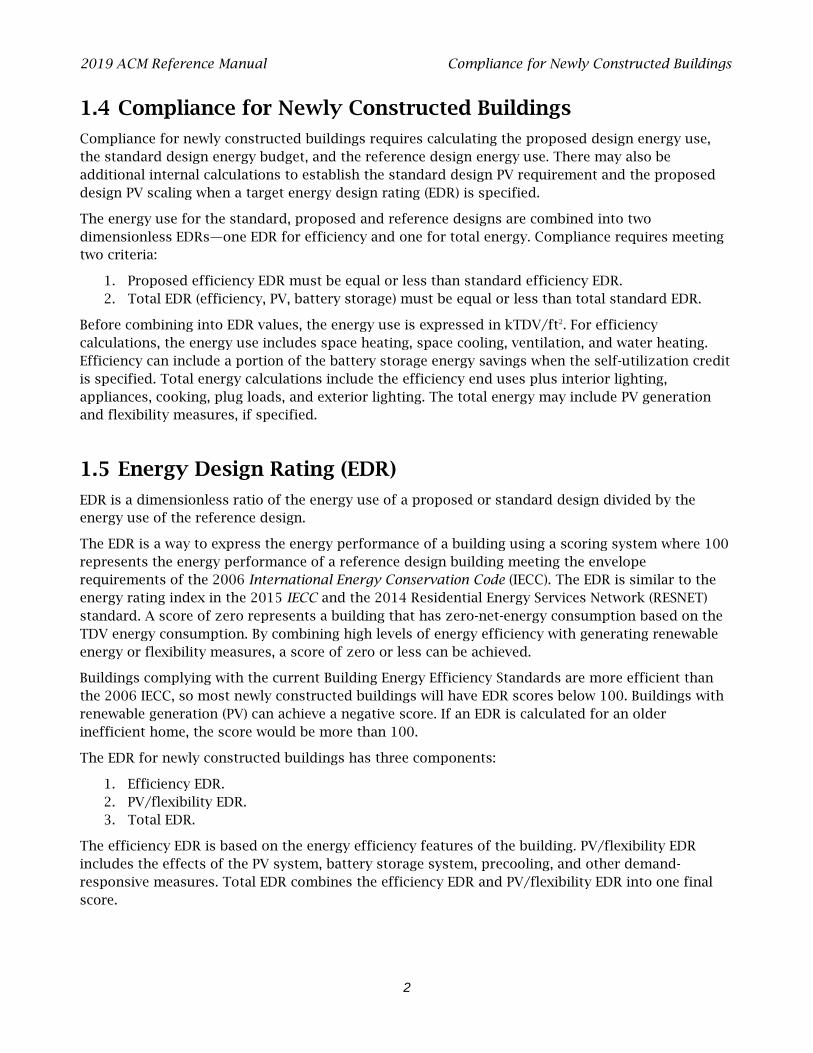
1.4 Compliance for Newly Constructed Buildings
Compliance for newly constructed buildings requires calculating the proposed design energy use, the standard design energy budget, and the reference design energy use. There may also be additional internal calculations to establish the standard design PV requirement and the proposed design PV scaling when a target energy design rating (EDR) is specified.
The energy use for the standard, proposed and reference designs are combined into two dimensionless EDRs—one EDR for efficiency and one for total energy. Compliance requires meeting two criteria:
1. Proposed efficiency EDR must be equal or less than standard efficiency EDR. 2. Total EDR (efficiency, PV, battery storage) must be equal or less than total standard EDR.
Before combining into EDR values, the energy use is expressed in kTDV/ft2. For efficiency calculations, the energy use includes space heating, space cooling, ventilation, and water heating. Efficiency can include a portion of the battery storage energy savings when the self-utilization credit is specified. Total energy calculations include the efficiency end uses plus interior lighting, appliances, cooking, plug loads, and exterior lighting. The total energy may include PV generation and flexibility measures, if specified.
1.5 Energy Design Rating (EDR)
EDR is a dimensionless ratio of the energy use of a proposed or standard design divided by the energy use of the reference design.
The EDR is a way to express the energy performance of a building using a scoring system where 100 represents the energy performance of a reference design building meeting the envelope requirements of the 2006 International Energy Conservation Code (IECC). The EDR is similar to the energy rating index in the 2015 IECC and the 2014 Residential Energy Services Network (RESNET) standard. A score of zero represents a building that has zero-net-energy consumption based on the TDV energy consumption. By combining high levels of energy efficiency with generating renewable energy or flexibility measures, a score of zero or less can be achieved.
Buildings complying with the current Building Energy Efficiency Standards are more efficient than the 2006 IECC, so most newly constructed buildings will have EDR scores below 100. Buildings with renewable generation (PV) can achieve a negative score. If an EDR is calculated for an older inefficient home, the score would be more than 100.
The EDR for newly constructed buildings has three components:
1. Efficiency EDR. 2. PV/flexibility EDR. 3. Total EDR.
The efficiency EDR is based on the energy efficiency features of the building. PV/flexibility EDR includes the effects of the PV system, battery storage system, precooling, and other demand-responsive measures. Total EDR combines the efficiency EDR and PV/flexibility EDR into one final score.
2019 ACM Reference Manual Self-Utilization Credit
3
The efficiency EDR does not include solar electric generation but can include a self-utilization credit for batteries. The total EDR includes the effects of solar generation and any battery storage beyond the self-utilization credit.
1.6 Self-Utilization Credit
When a PV system is coupled with battery storage system, the software allows a portion of the PV plus storage EDR to be traded against the efficiency EDR. This modest credit can be used for tradeoffs against building envelope and efficiencies of the equipment installed in the building. More detail is provided in 2.1.5.5.
1.7 Demand Response
Appropriate demand response controls allow building operators to reduce the total cost of energy by automating the response of a building to changes in electricity rates. Demand response is an increasingly important function as distributed energy resources become more common, as customers have access to time-of-use electricity rates, and incentive programs are designed to encourage customers to reduce energy during peak demand. Demand response occurs on a range of timescales from seconds to seasons and represents any demand change in response to grid or economic needs. In addition to current time-of-use electricity rates, in the future utilities will likely connect electricity costs to high-frequency fluctuations in supply and demand for electricity.
2019 ACM Reference Manual Overview
4
2 Proposed, Standard, and Reference Design
2.1 Overview
This chapter describes how the Energy Design Rating (EDR) is calculated, how the proposed design is modeled, and how the standard design is established.
2.1.1 Energy Design Rating (EDR)
The EDR is a score from zero to 100, where zero represents a building that has zero-net-energy consumption based on the time-dependent valuation (TDV) energy consumption, and 100 represents a building that is minimally compliant with the 2006 International Energy Conservation Code. The EDR score is a ratio of proposed design TDV budget to reference design TDV budget adjusted as described in Section 3.1. The EDR has three components:
1. Efficiency EDR
2. EDR of PV and demand flexibility
3. Total EDR is calculated by subtracting the PV/flexibility EDR from the efficiency EDR.
For a building to comply:
1. The EDR score of proposed efficiency must be equal or less than the EDR score of the standard efficiency.
2. Total proposed EDR score must be equal or less than the total standard design EDR score.
2.1.2 Proposed Design
The building configuration is defined by the user through entries that include floor areas, wall areas, roof and ceiling areas, fenestration (which includes skylights), and door areas. The performance characteristics such as U-factors, R-values, solar heat gain coefficient (SHGC), solar reflectance. Information about the orientation and tilt is required for roofs, fenestration, and other elements. Details about any solar generation systems and battery storage is also defined. The user entries for all these building elements are consistent with the actual building design and configuration. If the compliance software models the specific geometry of the building by using a coordinate system or graphic entry technique, the data generated are consistent with the actual building design and configuration.
2.1.3 Standard Design
For low-rise homes, the standard design building, from which the energy budget is established, is in the same location and has the same floor area, volume, and configuration as the proposed design, except that the wall and window areas are distributed equally among the four main compass points (north, east, south, and west). For additions and alterations, the standard design shall have the same wall and fenestration areas and orientations as the proposed building. The details are described below.

2019 ACM Reference Manual Overview
5
The energy budget for the residential standard design is the energy that would be used by a building similar to the proposed design if the proposed building met the requirements of the prescriptive standards. The compliance software generates the standard design automatically, based on fixed and restricted inputs and assumptions. Custom energy budget generation shall not be accessible to program users for modification when the program is used for compliance or when the program generates compliance forms.
The basis of the standard design is prescriptive requirements from Section 150.1(c) of the standards, Table 150.1-A or 150.1-B. Prescriptive requirements vary by climate zone. Reference Joint Appendix JA2, Table 2-1, contains the 16 California climate zones and representative cities. The climate zone is based on the zip code, as documented in JA2.1.1.
The following sections present the details of how the proposed design and standard design are determined. For many modeling assumptions, the standard design is the same as the proposed design. When a building has special features, for which the Energy Commission has established alternate modeling assumptions, the standard design features will differ from the proposed design so the building receives appropriate credit for its efficiency. When measures require verification by a Home Energy Rating System (HERS) rater or are designated as a special feature, the specific requirement is listed on the CF1R.
2.1.4 Reference Design
The reference design is calculated using the same inputs, assumptions and algorithms as the standard design except for the following requirements:
a. Air handler power. The air handler power is 0.8 W/CFM. b. Air infiltration rate. The air infiltration rate is 7.2 ACH50. c. Cooling airflow. The air handler airflow is 300 CFM/ton. d. Duct R-value. The duct R-value is R-8. e. Duct leakage rate. The duct leakage rate is modeled as an HVAC distribution efficiency of 80
percent. f. Quality insulation installation (QII). QII is modeled as “Yes.” g. Wall construction. Climate Zones 2-15 have 2x4 R-13 walls. Climate Zones 1 and 16 have 2x6
R-19 walls. h. Roof/ceiling construction. Climate Zones 2-15 have R-30 ceiling. Climate Zones 1 and 16 have
R-38 ceiling. No climate zones include radiant barriers or cool roofs. i. Raised floor construction. Climate Zones 2-15 have 2x10 R-19 floors. Climate Zones 1 and 16
have 2x10 R-30 floors. j. Slab edge insulation. Climate Zones 1 and 16 include R-10 insulation 24 inches deep. k. Window U-factors. Climate Zones 2-15 have 0.65 U-factor. Climate Zones 1 and 16 have 0.35
U-factor. l. Window SHGC. All windows have 0.4 SHGC. m. Window area. When the window area is below 18 percent of the floor area, the reference
design has the same area as the proposed design. Above 18 percent, the reference design has 18 percent.
n. HVAC equipment efficiencies. HVAC equipment meets National Appliance Energy Conservation Act (NAECA) requirements in effect in 2006 such as 78 percent AFUE for gas central furnace, and 13 SEER for central air-conditioning.
2019 ACM Reference Manual Overview
6
o. Water heating efficiency. Water heating modeled as a 40-gallon storage water with a 0.594 energy factor (EF) if gas or a 0.9172 EF if electric.
p. Appliance and plug load energy use and internal gains. Energy use and internal gains for appliance and miscellaneous plug loads are modeled as specified the ANSI/RESNET/ICC 301-2014 Standard.
2.1.5 Photovoltaics Requirements
The PV requirements are applicable to newly constructed low-rise residential buildings. PV system details are from PVWatts, which is a web application developed by the National Renewable Energy Laboratory (see Appendix F).
STANDARD DESIGN:
The standard design PV system (based on CFI assumptions) is sized to generate just enough electricity to offset the annual kWh consumption for a mixed fuel building that meets all the 2019 prescriptive requirements.
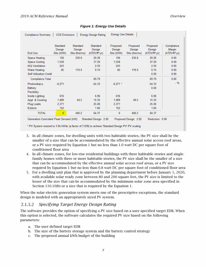
This standard design PV system is shown on the energy use details screen where the standard design site (kilowatt-hours [kWh]) total is zero after the PV is subtracted (Figure 1).
For PV sizing calculations, the software assumes the California flexible installation (CFI) orientation, standard efficiency for modules and inverters, fixed tracking, standard shading, and roof tilt of 22.61 degrees (5:12 pitch).
PROPOSED DESIGN
The proposed PV system is sized to generate the amount of electricity to offset the annual kWh load of the proposed design.
For PV sizing calculations, the software uses user-defined values for:
1. Array orientation, including CFI or actual orientation. 2. Module type, including standard (for example, poly- or monocrystalline silicon modules),
premium (e.g., high-efficiency monocrystalline silicon modules with antireflective coatings), or thin film (in other words, low efficiency such as 11 percent).
3. Inverter efficiency. 4. Array tilt in degrees or roof pitch. 5. Array tracking type including fixed, one-axis tracking, and two-axis tracking. 6. Actual shading of the modules.
The PV size is reported in kWdc.
Exceptions to the PV Requirements
1. No PV is required if the effective annual solar access is restricted to less than 80 contiguous square feet by shading from existing permanent natural or manmade barriers external to the dwelling, including but not limited to trees, hills, and adjacent structures.
2. In Climate Zone 15, the PV size shall be the smaller of a size that can be accommodated by the effective annual solar access roof areas, or a PV size required by Equation 1 but no less than 1.5 watt DC per square foot of conditioned floor area.
2019 ACM Reference Manual Overview
7
Figure 1: Energy Use Details
3. In all climate zones, for dwelling units with two habitable stories, the PV size shall be the smaller of a size that can be accommodated by the effective annual solar access roof areas, or a PV size required by Equation 1 but no less than 1.0 watt DC per square foot of conditioned floor area
4. In all climate zones, for low-rise residential buildings with three habitable stories and single-family homes with three or more habitable stories, the PV size shall be the smaller of a size that can be accommodated by the effective annual solar access roof areas, or a PV size required by Equation 1 but no less than 0.8 watt DC per square foot of conditioned floor area
5. For a dwelling unit plan that is approved by the planning department before January 1, 2020, with available solar ready zone between 80 and 200 square feet, the PV size is limited to the lesser of the size that can be accommodated by the minimum solar zone area specified in Section 110.10(b) or a size that is required by the Equation 1.
When the solar electric generation system meets one of the prescriptive exceptions, the standard design is modeled with an appropriately sized PV system.
Specifying Target Energy Design Rating
The software provides the option of specifying a PV size based on a user specified target EDR. When this option is selected, the software calculates the required PV size based on the following parameters:
a. The user defined target EDR b. The size of the battery storage system and the battery control strategy c. The proposed annual kWh budget of the building
2019 ACM Reference Manual Overview
8
Battery Storage
Detailed calculations for PV and battery storage are included in Appendices C and D.
The software provides credit for a battery storage system coupled with a PV array. If specified, the battery storage size must be 5 kWh or larger. For Part 6 compliance, PV has no impact on energy efficiency requirements or the efficiency EDR unless a battery storage system is included and the self-utilization credit is modeled.
Including a battery storage system allows downsizing the PV system to reach a specific EDR target.
Software includes a checkbox option to allow excess PV generation credit for above-code programs. This option, combined with a battery storage system, allows any PV size with full EDR credit.
Battery Controls
The three control options available are:
1. Basic (Default Control). A simple control strategy that provides a modest credit. The software assumes that the batteries are charged anytime PV generation (generation) is greater than the house load (load); conversely, the batteries are discharged when load exceeds generation. This control strategy does not allow the batteries to discharge into the grid.
2. Time of Use. To qualify for the TOU control, the battery storage system shall be installed in the default operation mode to allow charging from an on-site photovoltaic system. The battery storage system shall begin discharging during the highest priced TOU hours of the day, which varies by time of the year and the local utility. At a minimum, the system shall be capable of programming three seasonal TOU schedules, such as spring, summer, and winter.
3. Advanced DR Control. To qualify for the advanced demand response control, the battery storage system shall be programmed by default as basic control or TOU control, as described above. The battery storage control shall meet the demand responsive control requirements specified in Section 110.12(a). The battery storage system shall have the capability to change the charging and discharging periods in response to signals from the local utility or a third-party aggregator. Upon receiving a demand response signal from a grid operator, this option allows discharging directly into the grid.
VERIFICATION AND REPORTING
Battery system storage details are reported as special features on the CF1R.
Self-Utilization Credit
The 2019 Standards do not allow a tradeoff between the efficiency EDR and the effect of PV on the total EDR unless battery storage is provided. When the PV system is coupled with at least a 5 kWh battery storage system, the software allows a portion of the PV plus storage EDR to be traded against the efficiency EDR. A modest self-utilization credit can be used for tradeoffs against building envelope and efficiencies of the equipment installed in the building. A checkbox in provided in the software to enable this credit.
The magnitude of the credit is equal to the 90 percent of the difference between the 2019 and 2016 Standards envelope improvements, including:
1. Below-deck batt roof insulation value of R-19 for the 2019 Standards and R-13 for the 2016 Standard.
2019 ACM Reference Manual Overview
9
2. Wall U-factor of 0.48 for the 2019 Standards, and U-factor of 0.51 for the 2016 Standards. 3. Window U-factor of 0.30 for the 2019 Standards, and window U-factor of 0.32 for the 2016
Standards. 4. In cooling climate zones, window SHGC of 0.23 for the 2019 Standards, and 0.25 for the 2019
Standards. 5. New QII requirement in the 2019 standards, and no QII requirements in the 2016 Standards.
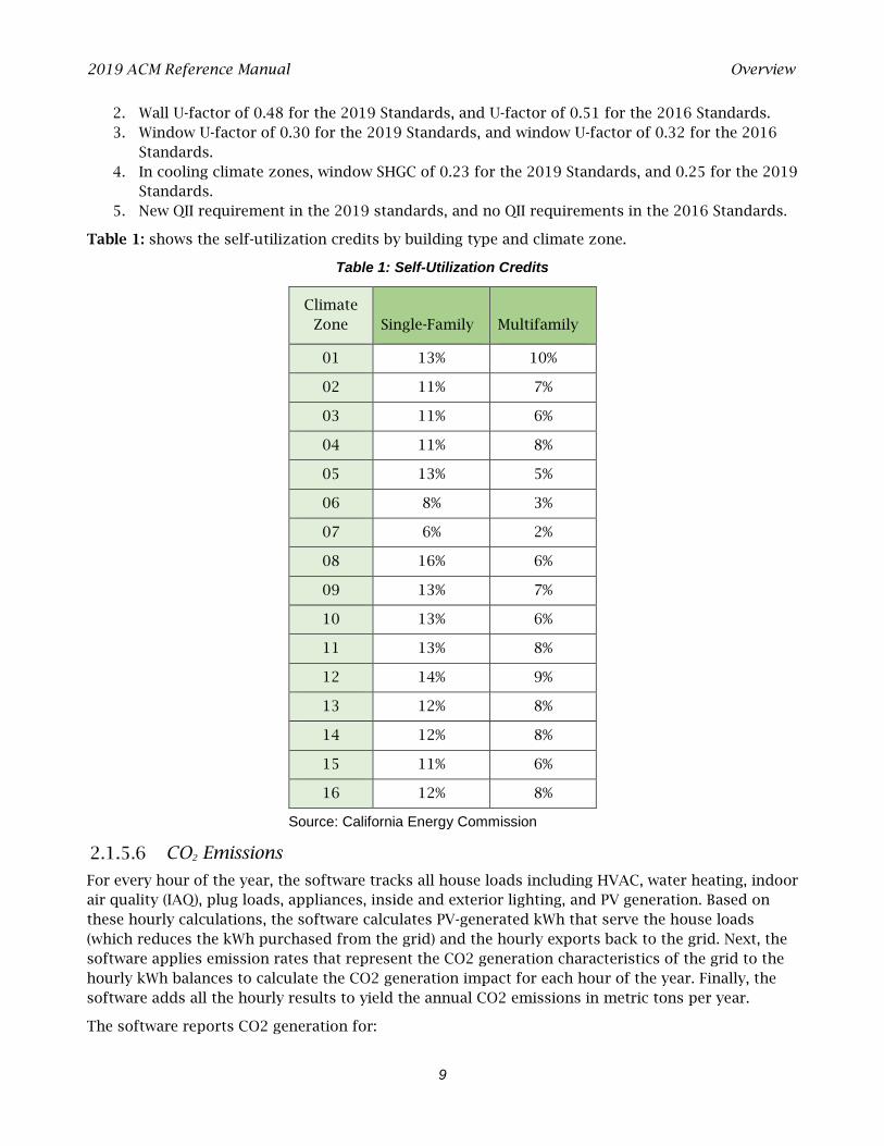
Table 1: shows the self-utilization credits by building type and climate zone.
Table 1: Self-Utilization Credits
Climate Zone Single-Family Multifamily
01 13% 10%
02 11% 7%
03 11% 6%
04 11% 8%
05 13% 5%
06 8% 3%
07 6% 2%
08 16% 6%
09 13% 7%
10 13% 6%
11 13% 8%
12 14% 9%
13 12% 8%
14 12% 8%
15 11% 6%
16 12% 8%
Source: California Energy Commission
CO2 Emissions
For every hour of the year, the software tracks all house loads including HVAC, water heating, indoor air quality (IAQ), plug loads, appliances, inside and exterior lighting, and PV generation. Based on these hourly calculations, the software calculates PV-generated kWh that serve the house loads (which reduces the kWh purchased from the grid) and the hourly exports back to the grid. Next, the software applies emission rates that represent the CO2 generation characteristics of the grid to the hourly kWh balances to calculate the CO2 generation impact for each hour of the year. Finally, the software adds all the hourly results to yield the annual CO2 emissions in metric tons per year.
The software reports CO2 generation for:
2019 ACM Reference Manual The Building
10
1. Total CO2 generation, and 2. CO2 generation excluding exports to the grid (self-use only).
Community Solar
A community-shared solar electric generation system, or other renewable electric generation system, and community shared battery storage system, which provides dedicated power, utility energy reduction credits, or payments for energy bill reductions or a combination thereof to the permitted building may offset part or all of the solar electric generation system EDR required to comply with the standards. The Energy Commission must approve the community solar system before it can be used for compliance (see Title 24, Part 1, Section 10-115).
The software has a pulldown menu of all Energy Commission approved community shared solar programs, and allows user to select a full or partial offset of the site PV requirements.
2.2 The Building
PROPOSED DESIGN
The building is defined through entries for zones, surfaces, and equipment. Zone types include attic, conditioned space, crawl space, basements, and garages. The roof (such as asphalt shingles or tile) is defined as either part of the attic or as part of a cathedral ceiling (also called a rafter roof). The software models Surfaces separating conditioned space from exterior or unconditioned spaces (such as a garage or storage) as interior surfaces adjacent to the unconditioned zone. Exterior surfaces of an attached garage or storage space are modeled as part of the unconditioned zone.
The input file will include entries for floor areas, wall, door, roof and ceiling areas, and fenestration and skylight areas, as well as the water heating, space-conditioning, ventilation, and distribution systems.
Each surface area is entered along with performance characteristics, including building materials, U-factor and SHGC. The orientation and tilt (Figure 2) are required for envelope elements.
Building elements are to be consistent with the actual building design and configuration.
STANDARD DESIGN
To determine the standard design for low-rise buildings, the software creates a building with the same general characteristics (number of stories, attached garage, climate zone) and with wall and window areas distributed equally among the four main compass points. Energy features are set to be equal to Section 150.1(c) and Table 150.1-A for single-family houses or Table 150.1-B for multifamily buildings. For additions and alterations, the standard design for existing features in the existing building shall have the same wall and fenestration areas and orientations as the proposed building. The details are below.
VERIFICATION AND REPORTING
All inputs that are used to establish compliance requirements are reported on the CF1R for verification.
2019 ACM Reference Manual The Building
11
REFERENCE DESIGN
To determine the reference design for low-rise buildings, a building with the same general inputs, assumptions and algorithms as the standard design building is modeled except for the following requirements:
a. Duct R-value. The duct R-value is R-8. b. Wall construction. Climate Zones 2-15 have 2x4 R-13 walls. Climate Zones 1 and 16 have 2x6
R-19 walls. c. Roof/ceiling construction. Climate Zones 2-15 have R-30 ceiling. Climate Zones 1 and 16 have
R-38 ceiling. No climate zones include radiant barriers or cool roofs. d. Floor construction. Climate Zones 2-15 have 2x10 R-19 floors. Climate Zones 1 and 16 have
2x10 R-30 floors. e. Slab edge insulation. Climate Zones 1 and 16 include R-10 insulation 24 inches deep. f. Window U-factors. Climate Zones 2-15 have a U-factor of 0,65. Climate Zones 1 and 16 have a
U-factor of 0.35. g. Window SHGC. All windows have 0.4 SHGC. h. Window area. When the window area is below 18 percent of the floor area, the reference
design has the same area as the proposed design. Above 18 percent, the reference design has 18 percent.
i. HVAC equipment efficiencies. HVAC equipment meets NAECA requirements in effect in 2006 such as 78 percent AFUE for gas central furnace, 13 SEER for central AC.
j. Water heating efficiency. Water heating modeled as a 40-gallon storage water with a 0.594 Energy Factor if gas or a 0.9172 Energy Factor if electric.
2.2.1 Climate and Weather
PROPOSED DESIGN
The user specifies the climate zone based on the zip code of the proposed building. Compliance requirements, weather, design temperatures, and time-dependent valuation (TDV) of energy factors are a function of the climate zone. Compliance software assumes that the ground surrounding residential buildings has a reflectivity of 20 percent in summer and winter.
STANDARD DESIGN
The standard design climate zone is the same as the proposed design.
VERIFICATION AND REPORTING
The zip code and climate zone of the proposed design are reported on the CF1R for verification.

2019 ACM Reference Manual The Building
12
Figure 2: Surface Definitions
Outside
Outside
Outside
Inside
Inside
Inside
Walls have a tiltgreater than 60but less than 120degrees from thehorizontal
Roofs have a tiltless than 60degrees from thehorizontal
Floors have a tiltof 180 degreesfrom thehorizontal
2.2.2 Standards Version
This input determines the appropriate federal appliance efficiency requirement for the standard design to compare with the proposed design.
PROPOSED DESIGN
The user inputs Compliance 2020.
STANDARD DESIGN
The standard design cooling equipment efficiency is based on the federal requirements. A minimum SEER and EER (if applicable) that meet the current standard for the type of equipment is modeled.
VERIFICATION AND REPORTING
Compliance version is reported on the CF1R.
2.2.3 Existing Condition Verified
These inputs are used for additions and alterations. The standard design assumption for existing conditions vary based on whether the existing conditions are verified by a home energy rating system (HERS) rater before construction. See Section 2.10.4 for more information.
PROPOSED DESIGN
The user inputs either yes or no. “Yes” indicates that the existing building conditions verified by a HERS rater. The default assumption is “no.”
STANDARD DESIGN
The standard design assumption is based on Section 150.2(b), Table 150.2-C. If the user input is “no,” the standard design for the existing component is based on the value in the second column. If the proposed design response is “yes,” the standard design value for the existing components is the value in the third column.
VERIFICATION AND REPORTING
Verification of existing conditions is a special feature and is reported in the HERS required verification listings on the CF1R.

2019 ACM Reference Manual The Building
13
2.2.4 Air Leakage and Infiltration
Air leakage is a building level characteristic. The compliance software distributes the leakage over the envelope surfaces in accordance with the building configuration and constructs a pressure flow network to simulate the airflows between the conditioned zones, unconditioned zones, and outside.
Building Air Leakage and Infiltration (ACH50)
The airflow through a blower door at 50 pascal (Pa) of pressure measured in cubic feet per minute is called CFM50. CFM50 x 60 minutes divided by the volume of conditioned space is the air changes per hour at 50 Pa, called ACH50.
Specific data on ACH50 may be entered if the single-family home or townhouse will have verified building air leakage testing. In multifamily buildings, due to the lack of an applicable measurement standard, ACH50 is fixed at the above defaults.
PROPOSED DESIGN
ACH50 defaults to 5 for new construction in single-family houses and townhomes and 7 for all other buildings that have heating and cooling system ducts or both outside conditioned space and for buildings with no cooling system. In single-family homes and townhomes with no heating or cooling system ducts or both in unconditioned space, the default ACH50 is 4.4 and 6.2 for all others.
Specific data on ACH50 may be entered if the single-family home or townhouse will have verified building air leakage testing. User input of an ACH50 that is less than the default value becomes a special feature requiring HERS verification.
Due to the lack of an applicable measurement standard, ACH50 is fixed at the above defaults and is not a compliance variable in multi-family buildings.
STANDARD DESIGN
The standard design shall have 5 ACH50 for single-family home and 7 for other buildings (ducted space-conditioning).
VERIFICATION AND REPORTING
When the user chooses verified building air leakage testing (any value less than the standard design), diagnostic testing for reduced infiltration, with details and target values modeled in the proposed design, is reported in the HERS required verification listing on the CF1R.
Defining Air Net Leakage
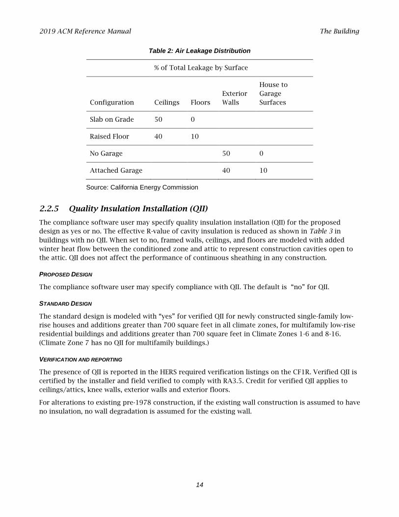
The compliance software creates an air leakage network for the proposed and standard design using the building description. Air leakage is distributed across the envelope surfaces according to the factors in Table 2. The air network is insensitive to wind direction. For buildings modeled with multiple conditioned zones, either a 20-square-foot open door or 30-square-foot open stairwell (in a multistory building) is assumed between any two conditioned zones.
The only difference between the air network for the proposed and standard designs is the ACH50 if the user specifies a value lower than the default.
Multifamily buildings that have floors between dwelling units must define each floor as a separate zone or each dwelling unit as a separate zone.
2019 ACM Reference Manual The Building
14
Table 2: Air Leakage Distribution
% of Total Leakage by Surface
Configuration Ceilings Floors Exterior Walls
House to Garage Surfaces
Slab on Grade 50 0
Raised Floor 40 10
No Garage
50 0
Attached Garage 40 10
Source: California Energy Commission
2.2.5 Quality Insulation Installation (QII)
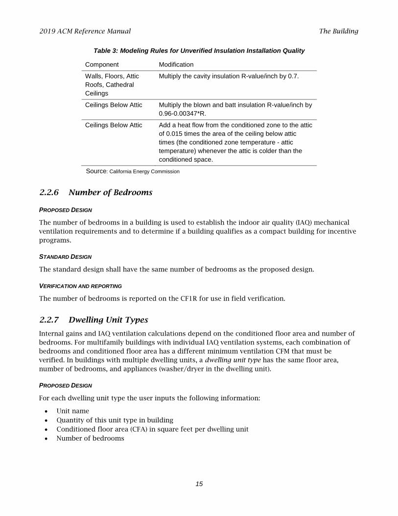
The compliance software user may specify quality insulation installation (QII) for the proposed design as yes or no. The effective R-value of cavity insulation is reduced as shown in Table 3 in buildings with no QII. When set to no, framed walls, ceilings, and floors are modeled with added winter heat flow between the conditioned zone and attic to represent construction cavities open to the attic. QII does not affect the performance of continuous sheathing in any construction.
PROPOSED DESIGN
The compliance software user may specify compliance with QII. The default is “no” for QII.
STANDARD DESIGN
The standard design is modeled with “yes” for verified QII for newly constructed single-family low-rise houses and additions greater than 700 square feet in all climate zones, for multifamily low-rise residential buildings and additions greater than 700 square feet in Climate Zones 1-6 and 8-16. (Climate Zone 7 has no QII for multifamily buildings.)
VERIFICATION AND REPORTING
The presence of QII is reported in the HERS required verification listings on the CF1R. Verified QII is certified by the installer and field verified to comply with RA3.5. Credit for verified QII applies to ceilings/attics, knee walls, exterior walls and exterior floors.
For alterations to existing pre-1978 construction, if the existing wall construction is assumed to have no insulation, no wall degradation is assumed for the existing wall.
2019 ACM Reference Manual The Building
15
Table 3: Modeling Rules for Unverified Insulation Installation Quality
Component Modification
Walls, Floors, Attic Roofs, Cathedral Ceilings
Multiply the cavity insulation R-value/inch by 0.7.
Ceilings Below Attic Multiply the blown and batt insulation R-value/inch by 0.96-0.00347*R.
Ceilings Below Attic Add a heat flow from the conditioned zone to the attic of 0.015 times the area of the ceiling below attic times (the conditioned zone temperature - attic temperature) whenever the attic is colder than the conditioned space.
Source: California Energy Commission
2.2.6 Number of Bedrooms
PROPOSED DESIGN
The number of bedrooms in a building is used to establish the indoor air quality (IAQ) mechanical ventilation requirements and to determine if a building qualifies as a compact building for incentive programs.
STANDARD DESIGN
The standard design shall have the same number of bedrooms as the proposed design.
VERIFICATION AND REPORTING
The number of bedrooms is reported on the CF1R for use in field verification.
2.2.7 Dwelling Unit Types
Internal gains and IAQ ventilation calculations depend on the conditioned floor area and number of bedrooms. For multifamily buildings with individual IAQ ventilation systems, each combination of bedrooms and conditioned floor area has a different minimum ventilation CFM that must be verified. In buildings with multiple dwelling units, a dwelling unit type has the same floor area, number of bedrooms, and appliances (washer/dryer in the dwelling unit).
PROPOSED DESIGN
For each dwelling unit type the user inputs the following information:
• Unit name • Quantity of this unit type in building • Conditioned floor area (CFA) in square feet per dwelling unit • Number of bedrooms
2019 ACM Reference Manual The Building
16
STANDARD DESIGN
The standard design shall have the same number and type of dwelling units as the proposed design.
VERIFICATION AND REPORTING
The number of units of each type and minimum IAQ ventilation for each unit is reported on the CF1R for field verification.
2.2.8 Front Orientation
The input for the building front orientation is the actual azimuth of the front of the building. This azimuth will generally be the side of the building facing the street or where the front door is located. The orientations of the other sides of a building viewed from the outside looking at the front door are called front, left, right, back, or a value relative to the front, and the compliance software calculates the actual azimuth from this input. Multiple orientation compliance can be selected for newly constructed buildings only.
PROPOSED DESIGN
The user specifies whether compliance is for multiple orientations or for a site-specific orientation. For site-specific orientation, the user inputs the actual azimuth of the front in degrees from true north.
STANDARD DESIGN
The compliance software constructs a standard design building that has 25 percent of the proposed model wall and window areas facing each cardinal orientation regardless of the proposed model distribution of wall and window area.
VERIFICATION AND REPORTING
A typical reported value would be "290 degrees (west)." This value would indicate that the front of the building faces north 70° west in surveyors’ terms. The closest orientation on 45° compass points should be reported in parentheses (for example, north, northeast, east, southeast, south, southwest, west, or northwest). When compliance is shown for multiple orientations, "all orientations" or “cardinal” is reported as a special feature on the CF1R and the energy use results are reported for four orientations including north, east, south, and west.
2.2.9 Gas Type
For newly constructed buildings, the standard design fuel type is based on the proposed design fuel type. The user specifies natural gas (if available) or propane, whether it is used for cooking appliances, clothes dryer, heating equipment, or water heating equipment. This specification is to establish the TDV values from Reference Appendices JA3 used by the compliance software to determine standard and proposed design energy use.
For projects with a run scope of “addition alone,” natural gas is available if a gas service line can be connected to the site without a gas main extension. Natural gas is available for existing plus addition/alteration projects if a gas service line is connected to the existing building.
2019 ACM Reference Manual The Building
17
PROPOSED DESIGN
The user specifies either natural gas, if it is available at the site, or propane.
STANDARD DESIGN
The standard design assumptions for space heating are as defined in Section 2.4.1 and for water heating are defined in Section 2.9.
2.2.10 Attached Garage
The user specifies whether there is an attached garage. The garage zone is modeled as an unconditioned zone (Section 2.8).
PROPOSED DESIGN
The user specifies whether there is an attached unconditioned garage.
STANDARD DESIGN
The standard design has the same attached garage assumption as the proposed design.
VERIFICATION AND REPORTING
Features of an attached garage are reported on the CF1R.
2.2.11 Lighting
The details of the calculation assumptions for lighting loads included Appendix E are based on the Codes and States Enhancement Initiative (CASE) report on plug loads and lighting (Rubin 2016, see Appendix F).
PROPOSED DESIGN
Fraction of portable lighting, power adjustment multiplier and the exterior lighting power adjustment multiplier (watts/ft2 – watts per square foot) are fixed assumptions.
STANDARD DESIGN
The standard design lighting is set equal to the proposed design lighting.
VERIFICATION AND REPORTING
No lighting information is reported on the CF1R for compliance with Title 24, Part 6.
2.2.12 Appliances
The details of the calculation assumptions for appliances and plug loads contained in Appendix E are based on the Codes and States Enhancement Initiative (CASE) report on plug loads and lighting (Rubin 2016, see Appendix F).
2019 ACM Reference Manual Building Materials and Construction
18
PROPOSED DESIGN
All buildings are assumed to have a refrigerator, dishwasher, and cooking appliance. Optionally, buildings can have a clothes washer and clothes dryer. The user can select fuel type as gas or electric for the clothes dryer and cooking appliance.
STANDARD DESIGN
The standard design appliances are set equal to the proposed appliances.
VERIFICATION AND REPORTING
No information for the appliance types listed above is reported on the CF1R for compliance with Title 24, Part 6.
2.3 Building Materials and Construction
2.3.1 Materials
Only materials approved by the Energy Commission may be used in defining constructions. Additional materials may be added to the compliance manager.
Table 4 shows a partial list of the materials available for construction assemblies.
MATERIAL NAME
The material name is used to select the material for a construction.
THICKNESS
Some materials, such as three-coat stucco, are defined with a specific thickness (not editable by the compliance user). The thickness of other materials, such as softwood used for framing, is selected by the compliance user based on the construction of the building.
CONDUCTIVITY
The conductivity of the material is the steady-state heat flow per square foot, per foot of thickness, or per degree Fahrenheit temperature difference. It is used in simulating the heat flow in the construction.
COEFFICIENT FOR TEMPERATURE ADJUSTMENT OF CONDUCTIVITY
The conductivity of insulation materials vary with temperature according to the coefficient listed. Other materials have a coefficient of zero (0), and the conductivity does not vary with temperature.
SPECIFIC HEAT
The specific heat is the amount of heat in British thermal units (Btu) it takes to raise the temperature of 1 pound of the material 1 degree Fahrenheit.
DENSITY
The density of the material is its weight in pounds per cubic foot.
2019 ACM Reference Manual Building Materials and Construction
19
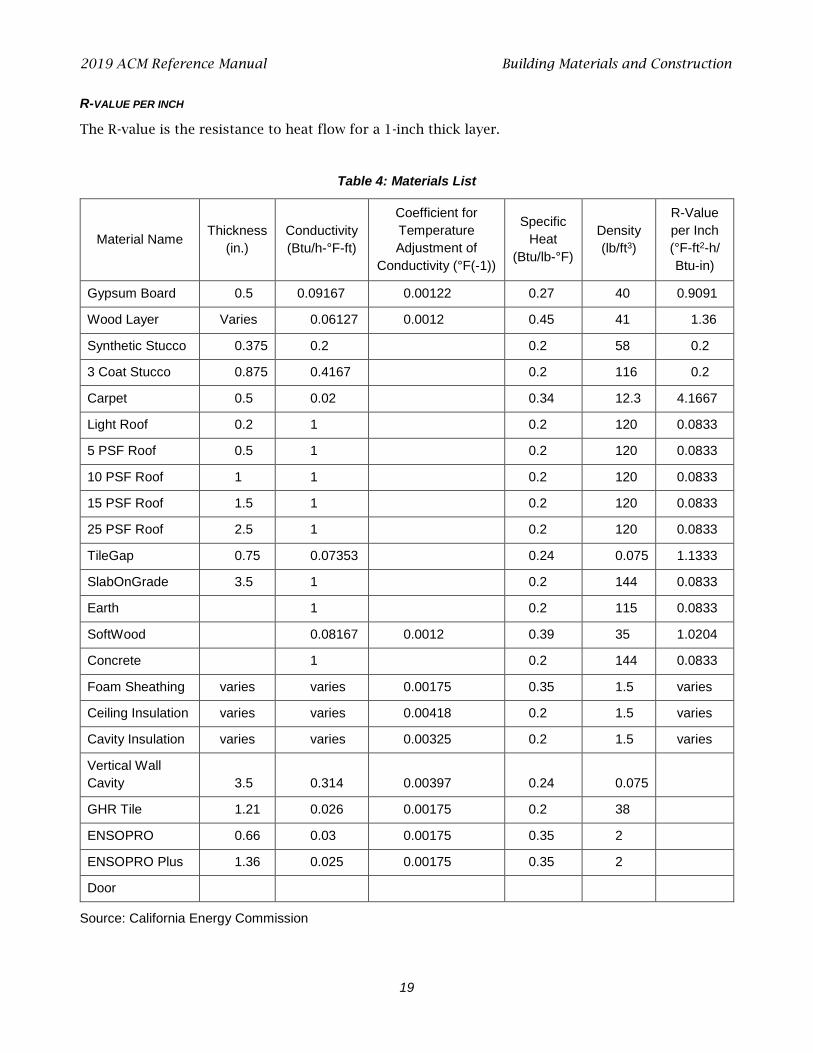
R-VALUE PER INCH
The R-value is the resistance to heat flow for a 1-inch thick layer.
Table 4: Materials List
Material Name Thickness (in.)
Conductivity (Btu/h-°F-ft)
Coefficient for Temperature Adjustment of
Conductivity (°F(-1))
Specific Heat
(Btu/lb-°F)
Density (lb/ft3)
R-Value per Inch (°F-ft2-h/ Btu-in)
Gypsum Board 0.5 0.09167 0.00122 0.27 40 0.9091
Wood Layer Varies 0.06127 0.0012 0.45 41 1.36
Synthetic Stucco 0.375 0.2 0.2 58 0.2
3 Coat Stucco 0.875 0.4167 0.2 116 0.2
Carpet 0.5 0.02 0.34 12.3 4.1667
Light Roof 0.2 1 0.2 120 0.0833
5 PSF Roof 0.5 1 0.2 120 0.0833
10 PSF Roof 1 1 0.2 120 0.0833
15 PSF Roof 1.5 1 0.2 120 0.0833
25 PSF Roof 2.5 1 0.2 120 0.0833
TileGap 0.75 0.07353 0.24 0.075 1.1333
SlabOnGrade 3.5 1 0.2 144 0.0833
Earth 1 0.2 115 0.0833
SoftWood 0.08167 0.0012 0.39 35 1.0204
Concrete 1 0.2 144 0.0833
Foam Sheathing varies varies 0.00175 0.35 1.5 varies
Ceiling Insulation varies varies 0.00418 0.2 1.5 varies
Cavity Insulation varies varies 0.00325 0.2 1.5 varies
Vertical Wall Cavity 3.5 0.314 0.00397 0.24 0.075
GHR Tile 1.21 0.026 0.00175 0.2 38
ENSOPRO 0.66 0.03 0.00175 0.35 2
ENSOPRO Plus 1.36 0.025 0.00175 0.35 2
Door
Source: California Energy Commission
2019 ACM Reference Manual Building Materials and Construction
20
2.3.2 Construction Assemblies
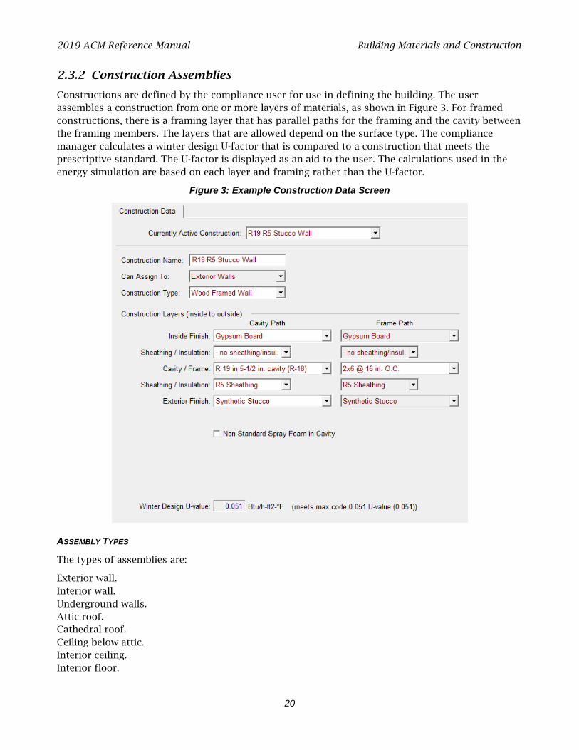
Constructions are defined by the compliance user for use in defining the building. The user assembles a construction from one or more layers of materials, as shown in Figure 3. For framed constructions, there is a framing layer that has parallel paths for the framing and the cavity between the framing members. The layers that are allowed depend on the surface type. The compliance manager calculates a winter design U-factor that is compared to a construction that meets the prescriptive standard. The U-factor is displayed as an aid to the user. The calculations used in the energy simulation are based on each layer and framing rather than the U-factor.
Figure 3: Example Construction Data Screen
ASSEMBLY TYPES
The types of assemblies are:
Exterior wall. Interior wall. Underground walls. Attic roof. Cathedral roof. Ceiling below attic. Interior ceiling. Interior floor.
2019 ACM Reference Manual Building Materials and Construction
21
Exterior floor (over unconditioned space or exterior). Floor over crawl space.
CONSTRUCTION TYPE
1. Ceiling below attic (the roof structure is not defined here, but is part of the attic), wood-framed. In a residence with a truss roof, the ceiling is where the insulation is located, while the structure above the ceiling is encompassed by the term “attic” or “roof.” The attic or roof consists of (moving from inside to outside) the radiant barrier, below-deck insulation, framing, above-deck insulation, and the roofing product, such as asphalt or tile roofing. See more in Section 2.4.5.
2. Cathedral ceiling (with the roof defined as part of the assembly), wood-framed. Since there is no attic, the roof structure is connected to the insulated assembly at this point.
3. Roof, structurally insulated panels (SIP).
4. Walls (interior, exterior, underground), wood- or metal-framed, or SIP.
5. Floors (over exterior, over crawl space, or interior).
6. Party surfaces separate conditioned space included in the analysis from conditioned space that may or may not be included in the analysis. Party surfaces for spaces that are modeled include surfaces between multifamily dwelling units. Party surfaces for spaces not included in the analysis include spaces joining an addition alone to the existing dwelling. Interior walls, ceilings, or floors can be party surfaces.
CONSTRUCTION LAYERS
All assemblies have a cavity path and a frame path.
Spray foam insulation R-values are either default values with no special inspection requirements or higher values when supported by an ESR number (see details Section 2.3.3 and RA3.5) verified by a HERS rater.
As assemblies are completed, the screen displays whether the construction meets the prescriptive requirement for that component.
PROPOSED DESIGN
The user defines a construction for each surface type included in the proposed design. Any variation in insulation R-value, framing size or spacing, interior or exterior sheathing, or interior or exterior finish requires the user to define a different construction. Insulation R-values are based on manufacturer-rated properties rounded to the nearest whole R-value. Layers such as sheetrock, wood sheathing, stucco, and carpet whose properties are not compliance variables are included as generic layers with standard thickness and properties.
Walls separating the house from an attached unconditioned attic or garage are modeled as interior walls with unconditioned space as the adjacent zone, which the compliance manager recognizes as a demising wall. Floors over a garage are modeled as an interior or demising floor. The exterior walls, floor, and ceiling/roof of the garage are modeled as part of the unconditioned garage zone.
STANDARD DESIGN
The compliance software assembles a construction that meets the prescriptive standards for each user-defined construction or assembly.

2019 ACM Reference Manual Building Materials and Construction
22
VERIFICATION AND REPORTING
All proposed constructions, including insulation, frame type, frame size, and exterior finish or exterior condition are listed on the CF1R. Nonstandard framing (e.g., 24” on center wall framing, advanced wall framing) is reported as a special feature.
2.3.3 Spray Foam Insulation
The R-values for spray-applied polyurethane foam (SPF) insulation differ depending on whether the product is open cell or closed cell.
Table 5: Required Thickness Spray Foam Insulation
Required R-values for SPF insulation R-11 R-13 R-15 R-19 R-21 R-22 R-25 R-30 R-38
Required thickness closed cell @ R5.8/inch
2.00 inches
2.25 inches
2.75 inches
3.50 inches
3.75 inches
4.00 inches
4.50 inches
5.25 inches
6.75 inches
Required thickness open cell @ R3.6/inch
3.0 inches
3.5 inches
4.2 inches
5.3 inches
5.8 inches
6.1 inches
6.9 inches
8.3 inches
10.6 inches
Source: California Energy Commission
Additional documentation and verification requirements for a value other than the default values shown in Table 5 is required. (See RA3.5.6.)
Medium Density Closed-Cell SPF Insulation
The default R-value for spray foam insulation with a closed cellular structure is R-5.8 per inch, based on the installed nominal thickness of insulation. Closed cell insulation has an installed nominal density of 1.5 to 2.5 pounds per cubic foot (pcf).
Low Density Open-Cell SPF Insulation
The default R-value for spray foam insulation with an open cellular structure is calculated as R-3.6 per inch based on the nominal required thickness of insulation. Open-cell insulation has an installed nominal density of 0.4 to 1.5 pounds per cubic foot (pcf).
PROPOSED DESIGN
The user will select either typical values for open-cell or closed-cell spray foam insulation or higher-than-typical values and enter the total R-value (rounded to the nearest whole value).
STANDARD DESIGN
The compliance software assembles a construction that meets the prescriptive standards for each assembly type (ceiling/roof, wall, and floor).
VERIFICATION AND REPORTING
When the user elects to use higher-than-typical R-values for open cell or closed cell spray foam insulation, a special features note is included on the CF1R requiring documentation requirements specified in RA4.1.7. Furthermore, a HERS verification requirement for the installation of spray foam insulation using higher-than-default values is included on the CF1R.
2019 ACM Reference Manual Building Mechanical Systems
23
2.4 Building Mechanical Systems
A space-conditioning system (also referred to as HVAC system) is made up of the heating subsystem (also referred to as “heating unit,” “heating equipment,” or “heating system”), cooling subsystem (also referred to as “cooling unit,” “cooling equipment,” or “cooling system”), the distribution subsystem details (if any), and fan subsystem (if any). Ventilation cooling systems and indoor air-quality-ventilation systems are defined at the building level for single-family homes or as part of the dwelling unit information for multifamily buildings. (See also Sections 2.4.9 and 2.4.10.)
2.4.1 Heating Subsystems
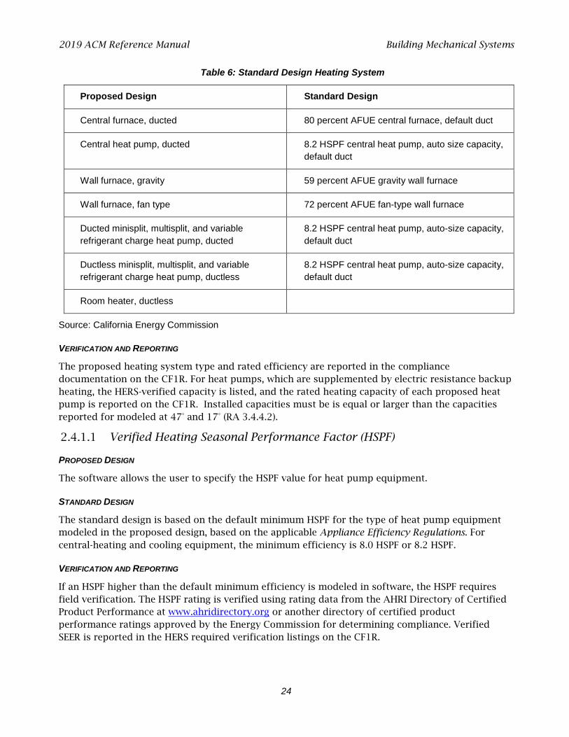
The heating subsystem describes the equipment that supplies heat to a space-conditioning system. Heating subsystems are categorized according to the types shown in Table 8.
PROPOSED DESIGN
The user selects the type and supplies required inputs for the heating subsystem including the appropriate rated heating efficiency. Except for heat pumps, the rated heating capacity is not used as a compliance variable by the compliance software.
When the proposed space-conditioning system is a heat pump, the user either allows the system capacity to be set automatically by the software or elects to specify rated heating capacity at 47°F
and 17°F for the heat pump compressor. The capacity is used to determine the effect of backup
electric resistance heat in the simulation. Either the user-entered or software-specified capacities are listed on the CF1R for verification by a HERS rater.
STANDARD DESIGN
When electricity is used for ducted heating, the heating equipment for the standard design is an electric split-system heat pump with default ducts in the attic and a heating seasonal performance factor (HSPF) meeting the current Appliance Efficiency Regulations minimum efficiency for split-systems. The standard design heat pump compressor size is determined by the software as the larger of the compressor size calculated for air-conditioning load, or the compressor with a 47°F rating that is 75 percent of the heating load (at the heating design temperature).
When electricity is used for a proposed ductless heating system, the standard design is a ductless system with the minimum HSPF from the Appliance Efficiency Regulations.
When proposed heating equipment is a ducted gas system, the equipment used in the standard design building is a gas furnace (or propane if natural gas is not available) with default ducts in the attic and an annual fuel utilization efficiency (AFUE) meeting the Appliance Efficiency Regulations minimum efficiency for central systems. When a proposed design uses both electric and non-electric heat, the standard design is a gas furnace.
See Table 6 for complete details on heating systems noted above and other possible proposed systems.
2019 ACM Reference Manual Building Mechanical Systems
24
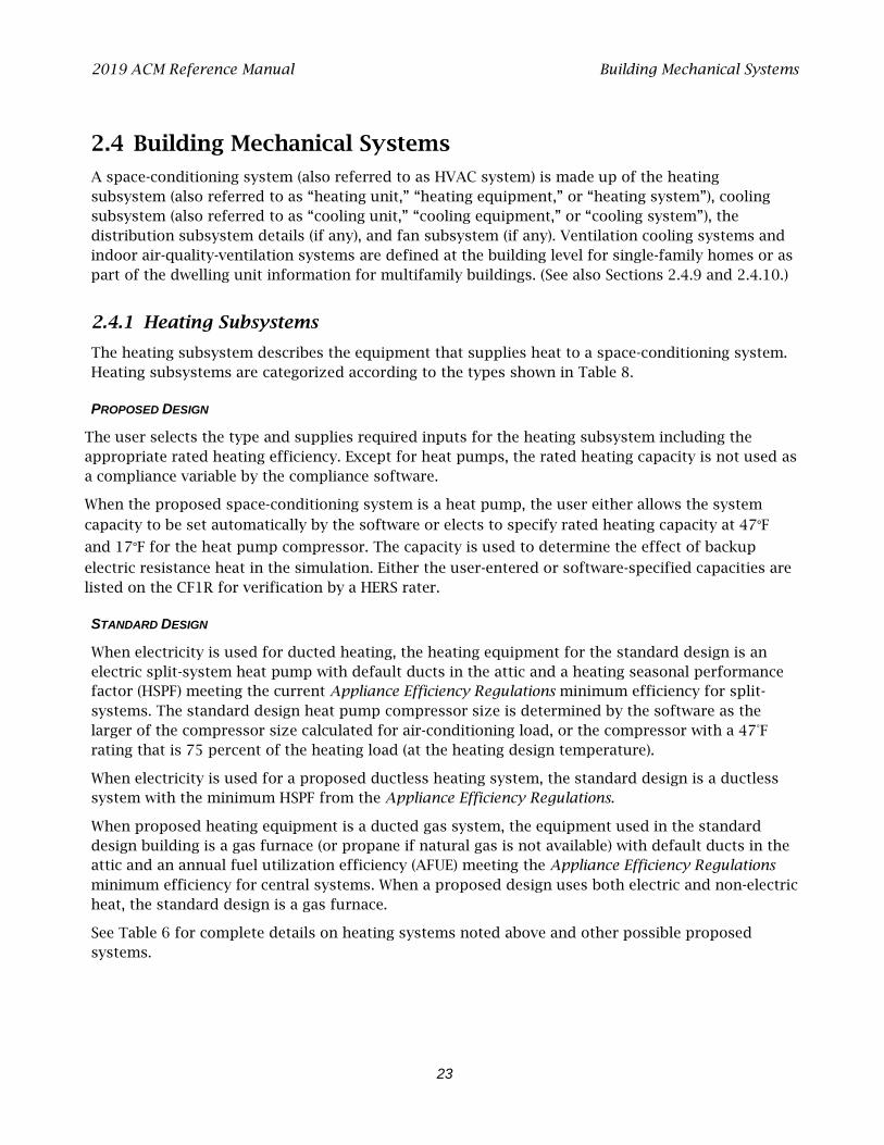
Table 6: Standard Design Heating System
Proposed Design Standard Design
Central furnace, ducted 80 percent AFUE central furnace, default duct
Central heat pump, ducted 8.2 HSPF central heat pump, auto size capacity, default duct
Wall furnace, gravity 59 percent AFUE gravity wall furnace
Wall furnace, fan type 72 percent AFUE fan-type wall furnace
Ducted minisplit, multisplit, and variable refrigerant charge heat pump, ducted
8.2 HSPF central heat pump, auto-size capacity, default duct
Ductless minisplit, multisplit, and variable refrigerant charge heat pump, ductless
8.2 HSPF central heat pump, auto-size capacity, default duct
Room heater, ductless
Source: California Energy Commission
VERIFICATION AND REPORTING
The proposed heating system type and rated efficiency are reported in the compliance documentation on the CF1R. For heat pumps, which are supplemented by electric resistance backup heating, the HERS-verified capacity is listed, and the rated heating capacity of each proposed heat pump is reported on the CF1R. Installed capacities must be is equal or larger than the capacities reported for modeled at 47° and 17° (RA 3.4.4.2).
Verified Heating Seasonal Performance Factor (HSPF)
PROPOSED DESIGN
The software allows the user to specify the HSPF value for heat pump equipment.
STANDARD DESIGN
The standard design is based on the default minimum HSPF for the type of heat pump equipment modeled in the proposed design, based on the applicable Appliance Efficiency Regulations. For central-heating and cooling equipment, the minimum efficiency is 8.0 HSPF or 8.2 HSPF.
VERIFICATION AND REPORTING
If an HSPF higher than the default minimum efficiency is modeled in software, the HSPF requires field verification. The HSPF rating is verified using rating data from the AHRI Directory of Certified Product Performance at www.ahridirectory.org or another directory of certified product performance ratings approved by the Energy Commission for determining compliance. Verified SEER is reported in the HERS required verification listings on the CF1R.

2019 ACM Reference Manual Building Mechanical Systems
25
Table 7: HVAC Heating Equipment Types
Name Heating Equipment Description
CntrlFurnace Gas- or oil-fired central furnaces, propane furnaces, or heating equipment considered equivalent to a gas-fired central furnace, such as wood stoves that qualify for the wood heat exceptional method. Gas fan-type central furnaces have a minimum AFUE=80%. Distribution can be gravity flow or use any of the ducted systems.
WallFurnaceGravity Noncentral gas- or oil-fired wall furnace, gravity flow. Equipment has varying efficiency requirements by capacity. Distribution is ductless.
WallFurnaceFan Noncentral gas- or oil-fired wall furnace, fan-forced. Equipment has varying efficiency requirements by capacity. Distribution is ductless.
FloorFurnace Noncentral gas- or oil-fired floor furnace. Equipment has varying efficiency requirements by capacity. Distribution is ductless.
RoomHeater Noncentral gas- or oil-fired room heaters. Noncentral gas- or oil-fired wall furnace, gravity flow. Equipment has varying efficiency requirements by capacity. Distribution is ductless.
WoodHeat Wood-fired stove. In areas with no natural gas available, a wood-heating system with any backup heating system is allowed to be installed if exceptional method criteria described in the Residential Compliance Manual are met.
Boiler Gas or oil boilers. Distribution systems can be radiant, baseboard, or any of the ducted systems. Boiler may be specified for dedicated hydronic systems. Systems in which the boiler provides space heating and fires an indirect gas water heater (IndGas) may be listed as Boiler/CombHydro Boiler and is listed under “Equipment Type” in the HVAC Systems listing.
Electric All electric heating systems other than space-conditioning heat pumps. Included are electric resistance heaters, electric boilers, and storage water heat pumps (air-water) (StoHP). Distribution system can be radiant, baseboard, or any of the ducted systems.
CombHydro Water-heating system can be storage gas (StoGas, LgStoGas) or storage electric (StoElec). Distribution systems can be radiant, baseboard, or any of the ducted systems and can be used with any of the terminal units (FanCoil, RadiantFlr, Baseboard, and FanConv).
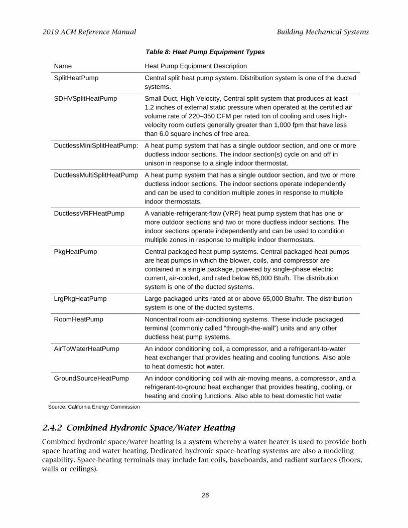
2019 ACM Reference Manual Building Mechanical Systems
26
Table 8: Heat Pump Equipment Types
Name Heat Pump Equipment Description
SplitHeatPump Central split heat pump system. Distribution system is one of the ducted systems.
SDHVSplitHeatPump Small Duct, High Velocity, Central split-system that produces at least 1.2 inches of external static pressure when operated at the certified air volume rate of 220–350 CFM per rated ton of cooling and uses high-velocity room outlets generally greater than 1,000 fpm that have less than 6.0 square inches of free area.
DuctlessMiniSplitHeatPump: A heat pump system that has a single outdoor section, and one or more ductless indoor sections. The indoor section(s) cycle on and off in unison in response to a single indoor thermostat.
DuctlessMultiSplitHeatPump A heat pump system that has a single outdoor section, and two or more ductless indoor sections. The indoor sections operate independently and can be used to condition multiple zones in response to multiple indoor thermostats.
DuctlessVRFHeatPump A variable-refrigerant-flow (VRF) heat pump system that has one or more outdoor sections and two or more ductless indoor sections. The indoor sections operate independently and can be used to condition multiple zones in response to multiple indoor thermostats.
PkgHeatPump Central packaged heat pump systems. Central packaged heat pumps are heat pumps in which the blower, coils, and compressor are contained in a single package, powered by single-phase electric current, air-cooled, and rated below 65,000 Btu/h. The distribution system is one of the ducted systems.
LrgPkgHeatPump Large packaged units rated at or above 65,000 Btu/hr. The distribution system is one of the ducted systems.
RoomHeatPump Noncentral room air-conditioning systems. These include packaged terminal (commonly called “through-the-wall”) units and any other ductless heat pump systems.
AirToWaterHeatPump An indoor conditioning coil, a compressor, and a refrigerant-to-water heat exchanger that provides heating and cooling functions. Also able to heat domestic hot water.
GroundSourceHeatPump An indoor conditioning coil with air-moving means, a compressor, and a refrigerant-to-ground heat exchanger that provides heating, cooling, or heating and cooling functions. Also able to heat domestic hot water
Source: California Energy Commission
2.4.2 Combined Hydronic Space/Water Heating
Combined hydronic space/water heating is a system whereby a water heater is used to provide both space heating and water heating. Dedicated hydronic space-heating systems are also a modeling capability. Space-heating terminals may include fan coils, baseboards, and radiant surfaces (floors, walls or ceilings).

2019 ACM Reference Manual Building Mechanical Systems
27
For combined hydronic systems, the water-heating portion is modeled normally. For space heating, an effective AFUE is calculated for gas water heaters. For electric water heaters, an effective HSPF is calculated. The procedures for calculating the effective AFUE or HSPF are described below.
Combined hydronic space-conditioning cannot be combined with zonal control credit.
PROPOSED DESIGN
When a fan coil is used to distribute heat, the fan energy and the heat contribution of the fan motor must be considered. The algorithms for fans used in combined hydronic systems are the same as those used for gas furnaces and are described in Chapter 3.
If a large fan coil is used and air-distribution ducts are located in the attic, crawl space, or other unconditioned space, the efficiency of the air-distribution system must be determined using methods consistent with those described in Section 2.4.6. Duct efficiency is accounted for when the distribution type is ducted.
Commercial or Consumer Storage Gas Water Heater
When storage gas water heaters are used in combined hydronic applications, the effective AFUE is given by the following equation:
−=
RIPLREAFUEeff Equation 1
Where:
AFUEeff = The effective AFUE of the gas water heater in satisfying the space heating load.
RE = The recovery efficiency (or thermal efficiency) of the gas storage water heater. A default value of 0.70 may be assumed if the recovery efficiency is unknown. This value is generally available from the Energy Commission appliance directory.
PL = Pipe losses (kBtu/h). This can be assumed to be zero when less than 10 feet of piping between the water heater storage tank and the fan coil or other heating elements are in unconditioned space.
RI = The rated input of the gas water heater (kBtu/h) available from the Energy Commission appliance directory.
Instantaneous Gas Water Heater
When instantaneous gas water heaters are used in combined hydronic applications, the effective AFUE is given by the following equation:
UEFAFUEeff = Equation 2
Where:
AFUEeff = The effective AFUE of the gas water heater in satisfying the space heating load.
UEF = The rated uniform energy factor of the instantaneous gas water heater.

2019 ACM Reference Manual Building Mechanical Systems
28
Storage Electric Water Heater
The HSPF of storage water heaters used for space heating in a combined hydronic system is given by the following equations.
−=
kWiPLHSPFeff 413.3
1413.3 Equation 3
Where:
HSPFeff = The effective HSPF of the electric water heater in satisfying the space heating load.
PL = Pipe losses (kBtu/h). Assumed zero when less than 10 feet of piping between the water heater storage tank and the fan coil or other heating elements are in unconditioned space.
kWi = The kilowatts of input to the water heater available from the Energy Commission’s
appliance directory.
STANDARD DESIGN
When a hydronic system is proposed to use electricity is used for heating, the heating equipment for the standard design is an electric split-system heat pump with an HSPF meeting the Appliance Efficiency Regulations requirements for split-systems. The standard design heat pump compressor size is determined by the software based on the compressor size calculated for the air-conditioning system.
When electricity is not used for heating, the equipment used in the standard design building is a gas furnace (or propane if natural gas is not available) with default ducts in the attic and an AFUE meeting the Appliance Efficiency Regulations minimum efficiency for central systems. When a proposed design uses both electric and non-electric heat, the standard design is a gas furnace.
2.4.3 Special Systems – Hydronic Distribution Systems and Terminals
[Not yet implemented]
PROPOSED DESIGN
This listing is completed for hydronic systems that have more than 10 feet of piping (plan view) in unconditioned space. As many rows as necessary may be used to describe the piping system.
STANDARD DESIGN
The standard design is established for a hydronic system in the same way as for a central system, as described in Section 2.4.1.
VERIFICATION AND REPORTING
A hydronic or combined hydronic system is reported on the CF1R.
Other information reported includes:
• Piping Run Length (ft). The length (plan view) of distribution pipe in unconditioned space, in feet, between the primary heating/cooling source and the point of distribution.

2019 ACM Reference Manual Building Mechanical Systems
29
• Nominal Pipe Size (in.). The nominal (as opposed to true) pipe diameter in inches. • Insulation Thickness (in.). The thickness of the insulation in inches. Enter "none" if the pipe is
uninsulated. • Insulation R-value (hr-ft2-°F/Btu). The installed R-value of the pipe insulation. Minimum pipe
insulation for hydronic systems is as specified in Section 150.0(j).
2.4.4 Ground-Source Heat Pump
A ground-source heat pump system, which uses the earth as a source of energy for heating and as a heat sink for energy when cooling, is simulated as a minimum efficiency split-system equivalent to the standard design with default duct conditions in place of the proposed system. The mandatory efficiencies for ground-source heat pumps are a minimum coefficient of performance (COP) for heating and EER for cooling.
2.4.5 Cooling Subsystems
The cooling subsystem describes the equipment that supplies cooling to a space-conditioning system.
PROPOSED DESIGN
Cooling subsystems are categorized according to the types shown in Table 9. The user selects the type of cooling equipment and enters basic information to model the energy use of the equipment. Enter the cooling equipment type and additional information based on the equipment type and zoning, such as the SEER and EER. For some types of equipment, the user may also specify that the equipment has a multispeed compressor and if the system is zoned or not via checkboxes. For ducted cooling systems, the cooling airflow from the conditioned zone through the cooling coil is input as CFM per ton. The rated cooling capacity is not a compliance variable.
Until there is an approved compliance option for ductless heat pumps (ductless minisplit, multisplit, and variable refrigerant flow [VRF] systems), these systems are simulated as a minimum efficiency split-system equivalent to the standard design with default duct conditions.
See sections below for the details of specific inputs.
STANDARD DESIGN
The cooling system for the standard design building is a non-zonal control system, of the same equipment type as the proposed system, meeting the minimum requirements of the Appliance Efficiency Regulations. The standard design system shall assume verified refrigerant charge in Climate Zones 2 and 8-15 for all ducted split-systems, ducted package systems, minisplit, multisplit, and VRF systems. Mandatory fan efficacy is assumed in all climate zones.
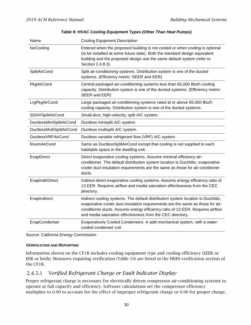
2019 ACM Reference Manual Building Mechanical Systems
30
Table 9: HVAC Cooling Equipment Types (Other Than Heat Pumps)
Name Cooling Equipment Description
NoCooling Entered when the proposed building is not cooled or when cooling is optional (to be installed at some future date). Both the standard design equivalent building and the proposed design use the same default system (refer to Section 2.4.8.3).
SplitAirCond Split air-conditioning systems. Distribution system is one of the ducted systems. (Efficiency metric: SEER and EER)
PkgAirCond Central packaged air-conditioning systems less than 65,000 Btu/h cooling capacity. Distribution system is one of the ducted systems. (Efficiency metric: SEER and EER)
LrgPkgAirCond Large packaged air-conditioning systems rated at or above 65,000 Btu/h cooling capacity. Distribution system is one of the ducted systems.
SDHVSplitAirCond Small-duct, high-velocity, split A/C system.
DuctlessMiniSplitAirCond Ductless minisplit A/C system.
DuctlessMultiSplitAirCond Ductless multisplit A/C system.
DuctlessVRFAirCond Ductless variable refrigerant flow (VRF) A/C system.
RoomAirCond Same as DuctlessSplitAirCond except that cooling is not supplied to each habitable space in the dwelling unit.
EvapDirect Direct evaporative cooling systems. Assume minimal efficiency air-conditioner. The default distribution system location is DuctAttic; evaporative cooler duct insulation requirements are the same as those for air-conditioner ducts.
EvapIndirDirect Indirect-direct evaporative cooling systems. Assume energy efficiency ratio of 13 EER. Requires airflow and media saturation effectiveness from the CEC directory.
EvapIndirect Indirect cooling systems. The default distribution system location is DuctAttic; evaporative cooler duct insulation requirements are the same as those for air-conditioner ducts. Assume energy efficiency ratio of 13 EER. Requires airflow and media saturation effectiveness from the CEC directory.
EvapCondenser Evaporatively Cooled Condensers. A split mechanical system, with a water-cooled condenser coil.
Source: California Energy Commission
VERIFICATION AND REPORTING
Information shown on the CF1R includes cooling equipment type and cooling efficiency (SEER or EER or both). Measures requiring verification (Table 10) are listed in the HERS verification section of the CF1R.
Verified Refrigerant Charge or Fault Indicator Display
Proper refrigerant charge is necessary for electrically driven compressor air-conditioning systems to operate at full capacity and efficiency. Software calculations set the compressor efficiency multiplier to 0.90 to account for the effect of improper refrigerant charge or 0.96 for proper charge.
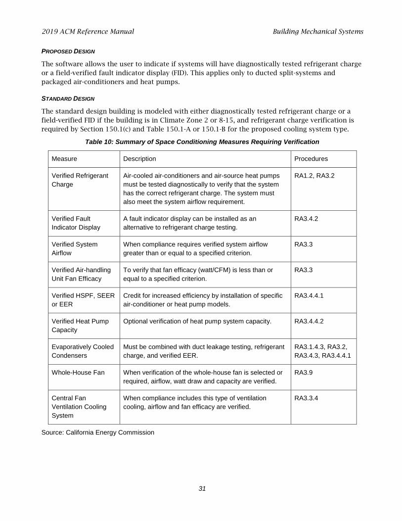
2019 ACM Reference Manual Building Mechanical Systems
31
PROPOSED DESIGN
The software allows the user to indicate if systems will have diagnostically tested refrigerant charge or a field-verified fault indicator display (FID). This applies only to ducted split-systems and packaged air-conditioners and heat pumps.
STANDARD DESIGN
The standard design building is modeled with either diagnostically tested refrigerant charge or a field-verified FID if the building is in Climate Zone 2 or 8-15, and refrigerant charge verification is required by Section 150.1(c) and Table 150.1-A or 150.1-B for the proposed cooling system type.
Table 10: Summary of Space Conditioning Measures Requiring Verification
Measure Description Procedures
Verified Refrigerant Charge
Air-cooled air-conditioners and air-source heat pumps must be tested diagnostically to verify that the system has the correct refrigerant charge. The system must also meet the system airflow requirement.
RA1.2, RA3.2
Verified Fault Indicator Display
A fault indicator display can be installed as an alternative to refrigerant charge testing.
RA3.4.2
Verified System Airflow
When compliance requires verified system airflow greater than or equal to a specified criterion.
RA3.3
Verified Air-handling Unit Fan Efficacy
To verify that fan efficacy (watt/CFM) is less than or equal to a specified criterion.
RA3.3
Verified HSPF, SEER or EER
Credit for increased efficiency by installation of specific air-conditioner or heat pump models.
RA3.4.4.1
Verified Heat Pump Capacity
Optional verification of heat pump system capacity. RA3.4.4.2
Evaporatively Cooled Condensers
Must be combined with duct leakage testing, refrigerant charge, and verified EER.
RA3.1.4.3, RA3.2, RA3.4.3, RA3.4.4.1
Whole-House Fan When verification of the whole-house fan is selected or required, airflow, watt draw and capacity are verified.
RA3.9
Central Fan Ventilation Cooling System
When compliance includes this type of ventilation cooling, airflow and fan efficacy are verified.
RA3.3.4
Source: California Energy Commission
2019 ACM Reference Manual Building Mechanical Systems
32
VERIFICATION AND REPORTING
Refrigerant charge or FID require field verification or diagnostic testing and are reported in the HERS required verification listings on the CF1R. Details on refrigerant charge measurement are discussed in Reference Residential Appendix RA3.2. Information on the requirements for FIDs is located in Reference Joint Appendix JA6.1.
Verified System Airflow
Adequate airflow from the conditioned space is required to allow ducted air-conditioning systems to operate at full efficiency and capacity. Efficiency is achieved by the air distribution system design by improving the efficiency of motors or by designing and installing air distribution systems that have less resistance to airflow. Software calculations account for the effect of airflow on sensible heat ratio and compressor efficiency.
For systems other than small-duct, high-velocity types, a value less than 350 CFM/ton (minimum 150 CFM/ton) is a valid input only if zonally controlled equipment is selected and multispeed compressor is not selected. Inputs less than 350 cfm/ton for zonally controlled systems require verification using procedures in Reference Residential Appendix RA3.3.
Section 150.0(m)13 requires verification that the central air-handling unit airflow rate is greater than or equal to 350 CFM/ton for systems other than small-duct, high-velocity types or 250 CFM/ton for small-duct, high-velocity systems. Values greater than the required CFM/ton may be input for compliance credit, which requires diagnostic testing using procedures in Reference Residential Appendix RA3.3.
For Single-Zone Systems:
• As an alternative to verification of 350 CFM/ton for systems other than small-duct, high-velocity types or 250 CFM/ton for small-duct, high-velocity systems, HERS verification of a return duct design that conforms to the specification given in Table 150.0-B or C may be used to demonstrate compliance.
• The return duct design alternative is not an input to the compliance software, but must be documented on the certificate of installation.
• If a value greater than 350 CFM/ton for systems other than small-duct, high-velocity types or greater than 250 CFM/ton for small-duct, high-velocity systems is modeled for compliance credit, the alternative return duct design method using Table 150.0-B or C is not allowed for demonstrating compliance.
• Multispeed or variable-speed compressor systems must verify airflow rate (CFM/ton) for system operation at the maximum compressor speed and the maximum air handler fan speed.
For Zonally Controlled Systems:
• The Table 150.0-B or C return duct design alternative is not allowed for zonally controlled systems.
• Multispeed, variable-speed, and single-speed compressor systems must all verify airflow rate (CFM/ton) by operating the system at maximum compressor capacity and maximum system fan speed with all zones calling for conditioning.
• Single-speed compressor systems must also verify airflow rate (CFM/ton) in every zonal control mode.
2019 ACM Reference Manual Building Mechanical Systems
33
• For systems that input less than 350 CFM/ton, HERS verification compliance cannot use group sampling.
PROPOSED DESIGN
The default cooling airflow is 150 CFM/ton for a system with “zonally controlled” selected and “multispeed compressor” not selected (single-speed). Users may model airflow for these systems greater than or equal to 150 CFM/ton, which must be verified using the procedures in Reference Residential Appendix RA3.3. Inputs less than the rates required by Section 150.0(m)13 will be penalized in the compliance calculation.
The default cooling airflow is 350 CFM/ton for systems other than small-duct, high-velocity types or 250 CFM/ton for small-duct, high-velocity systems. Users may model a higher-than-default airflow for these systems and receive credit in the compliance calculation if greater-than-default system airflow is diagnostically tested using the procedures of Reference Residential Appendix RA3.3.
STANDARD DESIGN
The standard design shall assume a system that complies with mandatory (Section 150.0) and prescriptive (Section 150.1) requirements for the applicable climate zone.
VERIFICATION AND REPORTING
The airflow rate verification compliance target (CFM or CFM/ton) is reported in the HERS required verification listings of the CF1R. When there is no cooling system, it is reported on the CF1R as a special feature.
Verified Air-Handling Unit Fan Efficacy
The mandatory requirement in Section 150.0(m)13 is for an air-handling unit fan efficacy less than or equal to 0.45 watts/CFM for gas furnace air-handling units, 0.58 watts/CFM for air-handling units that are not gas furnaces, and 0.62 W/CFM for small-duct, high-velocity systems as verified by a HERS rater. Users may model a lower fan efficacy (W/CFM) and receive credit in the compliance calculation if the proposed fan efficacy value is diagnostically tested using the procedures in Reference Residential Appendix RA3.3.
For Single-Zone Systems:
• Installers may elect to use an alternative to HERS verification of the watts/CFM required by Section 150.0(m)13: HERS verification of a return duct design that conforms to the specification given in Table 150.0-B or C.
• The return duct design alternative is not an input to the compliance software, but must be documented on the certificate of installation.
• If a value less than the watts/CFM required by 150.0(m)13 is modeled by the software user for compliance credit, the alternative return duct design method using Table 150.0-B or C is not allowed for use in demonstrating compliance.
• Multispeed or variable-speed compressor systems must verify fan efficacy (watt/CFM) for system operation at the maximum compressor speed and the maximum air handler fan speed.

2019 ACM Reference Manual Building Mechanical Systems
34
For Zonally Controlled Systems:
• The Table 150.0-B or C return duct design alternative is not allowed for zonally controlled systems.
• Multispeed, variable-speed and single-speed compressor systems must all verify fan efficacy (watt/CFM) by operating the system at maximum compressor capacity and maximum system fan speed with all zones calling for conditioning.
• Single-speed compressor systems must verify fan efficacy in every zonal control mode.
PROPOSED DESIGN
The software shall allow the user to enter the fan efficacy. The default mandatory value is 0.45, 0.58, or 0.62 W/CFM depending on the applicable system type. However, users may specify a lower value and receive credit in the compliance calculation if verified and diagnostically tested using the procedures of Reference Appendices, Residential Appendix RA3.3.
If no cooling system is installed, a default value of 0.45 W/CFM is assumed.
STANDARD DESIGN
The standard design shall assume a verified fan efficacy complying with the mandatory requirement of less than or equal to 0.45, 0.58, or 0.62 watts/CFM, depending on the applicable system type.
VERIFICATION AND REPORTING
For user inputs lower than the default mandatory 0.58 watts/cfm, Fan efficacy is reported in the HERS required verification listings of the CF1R.
For default mandatory 0.45 or 0.58 watts/cfm, the choice of either fan efficacy or alternative return duct design according to Table 150.0-B or C is reported in the HERS required verification listings of the CF1R.
No cooling system is reported as a special feature on the CF1R.
Verified Energy Efficiency Ratio (EER)
PROPOSED DESIGN
Software shall allow the user the option to enter an EER rating for central cooling equipment. For equipment that is rated only with an EER (room air-conditioners), the user will enter the EER. The Appliance Efficiency Regulations require a minimum SEER and EER for central cooling equipment. Only if a value higher than a default minimum EER is used is it reported as a HERS-verified measure.
STANDARD DESIGN
The standard design for central air-conditioning equipment is 11.7 EER.
VERIFICATION AND REPORTING
EER verification is required only if higher than 11.7 EER with 14 SEER is modeled or higher than the standard EER. The EER rating is verified using rating data from AHRI Directory of Certified Product Performance at www.ahridirectory.org or another directory of certified product performance ratings
2019 ACM Reference Manual Building Mechanical Systems
35
approved by the Energy Commission for determining compliance. Verified EER is reported in the HERS required verification listings on the CF1R.
Verified Seasonal Energy Efficiency Ratio (SEER)
PROPOSED DESIGN
The software allows the user to specify the SEER value.
STANDARD DESIGN
The standard design is based on the default minimum efficiency SEER for the type of cooling equipment modeled in the proposed design, based on the applicable Appliance Efficiency Regulations. For central-cooling equipment, the minimum efficiency is 14 SEER and 11.7 EER.
VERIFICATION AND REPORTING
If a SEER higher than the default minimum efficiency is modeled in software, the SEER requires field verification. The higher than minimum SEER rating is verified using rating data from AHRI Directory of Certified Product Performance at www.ahridirectory.org or another directory of certified product performance ratings approved by the Commission for determining compliance. Verified SEER is reported in the HERS required verification listings on the CF1R.
Verified Evaporatively-Cooled Condensers
PROPOSED DESIGN
Software shall allow users to specify an evaporatively-cooled condensing unit. The installation must comply with the requirements of RA4.3.2 to ensure the predicted energy savings are achieved. This credit must be combined with verified refrigerant charge testing, EER, and duct leakage testing.
STANDARD DESIGN
The standard design is based on a split-system air-conditioner meeting the requirements of Section 150.1(c) and Table 150.1-A or 150.1-B.
VERIFICATION AND REPORTING
An evaporatively-cooled condensing unit, verified EER, and duct leakage testing are reported in the HERS required verification listings on the CF1R.
Evaporative Cooling
Evaporative cooling technology is best suited for dry climates where direct, indirect, or indirect-direct cooling of the supply air stream can occur without compromising indoor comfort. Direct evaporative coolers are the most common system type currently available but provide less comfort and deliver more moisture to the indoor space. They are assumed equivalent to a minimum split-system air-conditioner. The evaporative cooling modeling method addresses two performance issues. The first performance issue is the increase in indoor relative humidity levels during periods with extended cooler operation. Since modeling of indoor air moisture levels is beyond the capability of simulation models, a simplified algorithm is used to prohibit evaporative cooler operation during load hours when operation is expected to contribute to uncomfortable indoor conditions. The algorithm disallows cooler operation when outdoor wet bulb temperatures are 70°F, or above. The second performance issue relates to evaporative cooler capacity limitations. Since

2019 ACM Reference Manual Building Mechanical Systems
36
evaporative coolers are 100 percent outdoor air systems, the related capacity is limited by the outdoor wet bulb temperature. Each hour with calculated cooling load, the algorithm will verify that the cooling capacity is greater than the calculated cooling load.
PROPOSED DESIGN
Software shall allow users to specify one of three types of evaporative cooling: (1) direct evaporative cooler, the most commonly available system type;, (2) indirect; or (3) indirect-direct. Product specifications and other modeling details are found in the Energy Commission appliance directory for evaporative cooling. Direct system types are assigned an efficiency of 14 SEER (or minimum appliance efficiency standard for split-system cooling). The default system type is evaporative direct. For indirect or indirect-direct, select the appropriate type from the Energy Commission appliance directory and input a 13 EER as well as the airflow and media saturation effectiveness or cooling effectiveness from the Energy Commission appliance directory.
STANDARD DESIGN
The standard design is based on a split-system air-conditioner meeting the requirements of Section 150.1(c) and Table 150.1-A or 150.1-B.
VERIFICATION AND REPORTING
When a direct evaporative cooling system is modeled, the system type and minimum efficiency are shown in the appropriate section of the CF1R. When indirect or indirect-direct evaporative cooling are modeled, the EER verification is shown in the HERS verification section of the CF1R along with the system type, airflow, and system effectiveness.
2.4.6 Distribution Subsystems
If multiple HVAC distribution systems serve a building, each system and the conditioned space it serves may be modeled in detail separately or the systems may be aggregated and modeled as one large system. If the systems are aggregated, they must be the same type and all meet the same minimum specifications.
For duct efficiency calculations, the supply duct begins at the exit from the furnace or air handler cabinet.
Distribution Type
Fan-powered, ducted distribution systems can be used with most heating or cooling systems. When ducted systems are used with furnaces, boilers, or combined hydronic/water heating systems, the electricity used by the fan is calculated. R-value and duct location are specified when a ducted system is specified.
PROPOSED DESIGN
The compliance software shall allow the user to select from the basic types of HVAC distribution systems and locations listed in Table 11. For ducted systems, the default location of the HVAC ducts and the air handler are in conditioned space for multifamily buildings and in the attic for all other buildings.

2019 ACM Reference Manual Building Mechanical Systems
37
Table 11: HVAC Distribution Type and Location Descriptors
Name HVAC Distribution Type and Location Description
Ducts located in attic (Ventilated and Unventilated)
Ducts located overhead in the attic space.
Ducts located in a crawl space Ducts located under floor in the crawl space.
Ducts located in a garage Ducts located in an unconditioned garage space.
Ducts located within the conditioned space (except < 12 linear ft)
Ducts located within the conditioned floor space except for less than 12 linear feet of duct, furnace cabinet, and plenums - typically an HVAC unit in the garage mounted on return box with all other ducts in conditioned space.
Ducts located entirely in conditioned space
HVAC unit or systems with all HVAC ducts (supply and return) located within the conditioned floor space. Location of ducts in conditioned space eliminates conduction losses, but does not change losses due to leakage. Leakage either from ducts that are not tested for leakage or from sealed ducts is modeled as leakage to outside the conditioned space.
Distribution system without ducts (none)
Air distribution systems without ducts such as ductless split-system air-conditioners and heat pumps, window air-conditioners, through-the-wall heat pumps, wall furnaces, floor furnaces, radiant electric panels, combined hydronic heating equipment, electric baseboards, or hydronic baseboard finned-tube natural convection systems, etc.
Ducts located in outdoor locations Ducts located in exposed locations outdoors.
Verified low-leakage ducts located entirely in conditioned space
Duct systems for which air leakage to outside is equal to or less than 25 CFM when measured in accordance with Reference Residential Appendix RA3.1.4.3.8.
Ducts located in multiple places Ducts with different supply and return duct locations.
Source: California Energy Commission
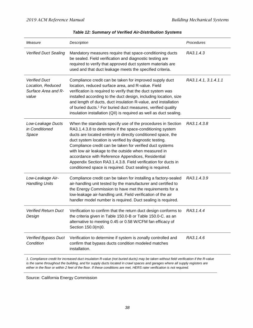
2019 ACM Reference Manual Building Mechanical Systems
38
Table 12: Summary of Verified Air-Distribution Systems
Measure Description Procedures
Verified Duct Sealing Mandatory measures require that space-conditioning ducts be sealed. Field verification and diagnostic testing are required to verify that approved duct system materials are used and that duct leakage meets the specified criteria.
RA3.1.4.3
Verified Duct Location, Reduced Surface Area and R-value
Compliance credit can be taken for improved supply duct location, reduced surface area, and R-value. Field verification is required to verify that the duct system was installed according to the duct design, including location, size and length of ducts, duct insulation R-value, and installation of buried ducts.1 For buried duct measures, verified quality insulation installation (QII) is required as well as duct sealing.
RA3.1.4.1, 3.1.4.1.1
Low-Leakage Ducts in Conditioned Space
When the standards specify use of the procedures in Section RA3.1.4.3.8 to determine if the space-conditioning system ducts are located entirely in directly conditioned space, the duct system location is verified by diagnostic testing. Compliance credit can be taken for verified duct systems with low air leakage to the outside when measured in accordance with Reference Appendices, Residential Appendix Section RA3.1.4.3.8. Field verification for ducts in conditioned space is required. Duct sealing is required.
RA3.1.4.3.8
Low-Leakage Air-Handling Units
Compliance credit can be taken for installing a factory-sealed air-handling unit tested by the manufacturer and certified to the Energy Commission to have met the requirements for a low-leakage air-handling unit. Field verification of the air handler model number is required. Duct sealing is required.
RA3.1.4.3.9
Verified Return Duct Design
Verification to confirm that the return duct design conforms to the criteria given in Table 150.0-B or Table 150.0-C. as an alternative to meeting 0.45 or 0.58 W/CFM fan efficacy of Section 150.0(m)0.
RA3.1.4.4
Verified Bypass Duct Condition
Verification to determine if system is zonally controlled and confirm that bypass ducts condition modeled matches installation.
RA3.1.4.6
1. Compliance credit for increased duct insulation R-value (not buried ducts) may be taken without field verification if the R-value is the same throughout the building, and for supply ducts located in crawl spaces and garages where all supply registers are either in the floor or within 2 feet of the floor. If these conditions are met, HERS rater verification is not required.
Source: California Energy Commission
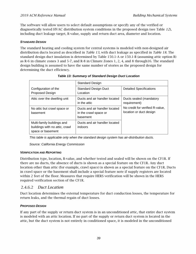
2019 ACM Reference Manual Building Mechanical Systems
39
The software will allow users to select default assumptions or specify any of the verified or diagnostically tested HVAC distribution system conditions in the proposed design (see Table 12), including duct leakage target, R-value, supply and return duct area, diameter and location.
STANDARD DESIGN
The standard heating and cooling system for central systems is modeled with non-designed air distribution ducts located as described in Table 13, with duct leakage as specified in Table 18. The standard design duct insulation is determined by Table 150.1-A or 150.1-B (assuming attic option B) as R-6 in climate zones 3 and 5-7, and R-8 in Climate Zones 1, 2, 4, and 8 through16. The standard design building is assumed to have the same number of stories as the proposed design for determining the duct efficiency.
Table 13: Summary of Standard Design Duct Location
Configuration of the Proposed Design
Standard Design
Standard Design Duct Location
Detailed Specifications
Attic over the dwelling unit Ducts and air handler located in the attic
Ducts sealed (mandatory requirement) No credit for verified R-value, location or duct design
No attic but crawl space or basement
Ducts and air handler located in the crawl space or basement
Multi-family buildings and buildings with no attic, crawl space or basement
Ducts and air handler located indoors
This table is applicable only when the standard design system has air-distribution ducts.
Source: California Energy Commission
VERIFICATION AND REPORTING
Distribution type, location, R-value, and whether tested and sealed will be shown on the CF1R. If there are no ducts, the absence of ducts is shown as a special feature on the CF1R. Any duct location other than attic (for example, crawl space) is shown as a special feature on the CF1R. Ducts in crawl space or the basement shall include a special feature note if supply registers are located within 2 feet of the floor. Measures that require HERS verification will be shown in the HERS required verification section of the CF1R.
Duct Location
Duct location determines the external temperature for duct conduction losses, the temperature for return leaks, and the thermal regain of duct losses.
PROPOSED DESIGN
If any part of the supply or return duct system is in an unconditioned attic, that entire duct system is modeled with an attic location. If no part of the supply or return duct system is located in the attic, but the duct system is not entirely in conditioned space, it is modeled in the unconditioned

2019 ACM Reference Manual Building Mechanical Systems
40
zone, which contains the largest fraction of the surface area. If the supply or return duct system is entirely in conditioned space, the duct system is modeled in conditioned space.
For ducted HVAC systems with some or all ducts in unconditioned space, the user specifies the R-value and surface area of supply and return ducts and the duct location.
Duct location and areas other than the defaults shown in Table 14 may be used following the verification procedures in Reference Residential Appendix RA3.1.4.1.
STANDARD DESIGN
The standard design duct location is determined from the building conditions (Table 13).
VERIFICATION AND REPORTING
Duct location is reported on the CF1R. Ducts entirely in conditioned space and verified low-leakage ducts entirely in conditioned space are reported in the HERS required verification listing on the CF1R.
Default duct locations are shown in Table 14. The duct surface area for crawl space and basement applies only to buildings or zones with all ducts installed in the crawl space or basement. If the duct is installed in locations other than crawl space or basement, the default duct location is “Other.” For houses with two or more stories, 35 percent of the default duct area may be assumed to be in conditioned space, as shown in Table 14.
The surface area of ducts in conditioned space is ignored in calculating conduction losses.
Table 14: Location of Default Duct Area
Supply Duct Location Location of Default Duct Surface Area
One story Two or more stories
All in crawl space 100% crawl space 65% crawl space, 35% conditioned space
All in basement 100% basement 65% basement, 35% conditioned space
Other 100% attic 65% attic, 35% conditioned space
Source: California Energy Commission
Duct Surface Area
The supply-side and return-side duct surface areas are treated separately in distribution efficiency calculations. The duct surface area is determined using the following methods.
Default Return Duct Surface Area
Default return duct surface area is calculated using:
floorroutr, AK A ×= Equation 4
Where Kr (return duct surface area coefficient) is 0.05 for one-story buildings and 0.1 for two or more stories.
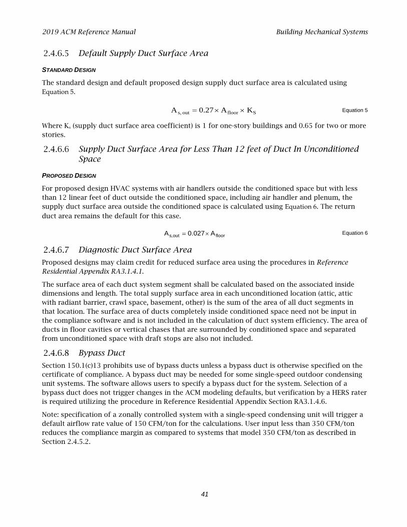
2019 ACM Reference Manual Building Mechanical Systems
41
Default Supply Duct Surface Area
STANDARD DESIGN
The standard design and default proposed design supply duct surface area is calculated using Equation 5.
Sfloorout s, KA0.27A ××= Equation 5
Where Ks (supply duct surface area coefficient) is 1 for one-story buildings and 0.65 for two or more stories.
Supply Duct Surface Area for Less Than 12 feet of Duct In Unconditioned Space
PROPOSED DESIGN
For proposed design HVAC systems with air handlers outside the conditioned space but with less than 12 linear feet of duct outside the conditioned space, including air handler and plenum, the supply duct surface area outside the conditioned space is calculated using Equation 6. The return
duct area remains the default for this case.
floorout,s A027.0A ×=
Equation 6
Diagnostic Duct Surface Area
Proposed designs may claim credit for reduced surface area using the procedures in Reference Residential Appendix RA3.1.4.1.
The surface area of each duct system segment shall be calculated based on the associated inside dimensions and length. The total supply surface area in each unconditioned location (attic, attic with radiant barrier, crawl space, basement, other) is the sum of the area of all duct segments in that location. The surface area of ducts completely inside conditioned space need not be input in the compliance software and is not included in the calculation of duct system efficiency. The area of ducts in floor cavities or vertical chases that are surrounded by conditioned space and separated from unconditioned space with draft stops are also not included.
Bypass Duct
Section 150.1(c)13 prohibits use of bypass ducts unless a bypass duct is otherwise specified on the certificate of compliance. A bypass duct may be needed for some single-speed outdoor condensing unit systems. The software allows users to specify a bypass duct for the system. Selection of a bypass duct does not trigger changes in the ACM modeling defaults, but verification by a HERS rater is required utilizing the procedure in Reference Residential Appendix Section RA3.1.4.6.
Note: specification of a zonally controlled system with a single-speed condensing unit will trigger a default airflow rate value of 150 CFM/ton for the calculations. User input less than 350 CFM/ton reduces the compliance margin as compared to systems that model 350 CFM/ton as described in Section 2.4.5.2.
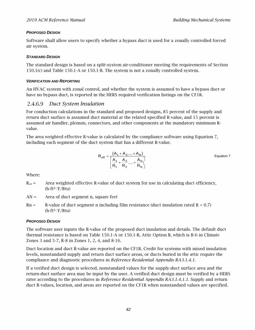
2019 ACM Reference Manual Building Mechanical Systems
42
PROPOSED DESIGN
Software shall allow users to specify whether a bypass duct is used for a zonally controlled forced air system.
STANDARD DESIGN
The standard design is based on a split-system air-conditioner meeting the requirements of Section 150.1(c) and Table 150.1-A or 150.1-B. The system is not a zonally controlled system.
VERIFICATION AND REPORTING
An HVAC system with zonal control, and whether the system is assumed to have a bypass duct or have no bypass duct, is reported in the HERS required verification listings on the CF1R.
Duct System Insulation
For conduction calculations in the standard and proposed designs, 85 percent of the supply and return duct surface is assumed duct material at the related specified R-value, and 15 percent is assumed air handler, plenum, connectors, and other components at the mandatory minimum R-value.
The area weighted effective R-value is calculated by the compliance software using Equation 7, including each segment of the duct system that has a different R-value.
++
++=
N
N
2
2
1
1
N21eff
RA ....
RA
RA
)A....AA(R Equation 7
Where:
Reff = Area weighted effective R-value of duct system for use in calculating duct efficiency, (h-ft²-°F/Btu)
AN = Area of duct segment n, square feet
Rn = R-value of duct segment n including film resistance (duct insulation rated R + 0.7) (h-ft²-°F/Btu)
PROPOSED DESIGN
The software user inputs the R-value of the proposed duct insulation and details. The default duct thermal resistance is based on Table 150.1-A or 150.1-B, Attic Option B, which is R-6 in Climate Zones 3 and 5-7, R-8 in Zones 1, 2, 4, and 8-16.
Duct location and duct R-value are reported on the CF1R. Credit for systems with mixed insulation levels, nonstandard supply and return duct surface areas, or ducts buried in the attic require the compliance and diagnostic procedures in Reference Residential Appendix RA3.1.4.1.
If a verified duct design is selected, nonstandard values for the supply-duct surface area and the return-duct surface area may be input by the user. A verified duct design must be verified by a HERS rater according to the procedures in Reference Residential Appendix RA3.1.4.1.1. Supply and return duct R-values, location, and areas are reported on the CF1R when nonstandard values are specified.
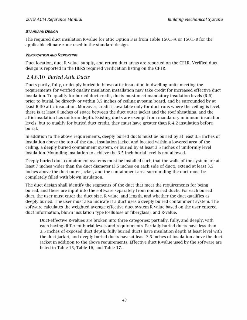
2019 ACM Reference Manual Building Mechanical Systems
43
STANDARD DESIGN
The required duct insulation R-value for attic Option B is from Table 150.1-A or 150.1-B for the applicable climate zone used in the standard design.
VERIFICATION AND REPORTING
Duct location, duct R-value, supply, and return duct areas are reported on the CF1R. Verified duct design is reported in the HERS required verification listing on the CF1 R.
Buried Attic Ducts
Ducts partly, fully, or deeply buried in blown attic insulation in dwelling units meeting the requirements for verified quality insulation installation may take credit for increased effective duct insulation. To qualify for buried duct credit, ducts must meet mandatory insulation levels (R-6) prior to burial, be directly or within 3.5 inches of ceiling gypsum board, and be surrounded by at least R-30 attic insulation. Moreover, credit is available only for duct runs where the ceiling is level, there is at least 6 inches of space between the duct outer jacket and the roof sheathing, and the attic insulation has uniform depth. Existing ducts are exempt from mandatory minimum insulation levels, but to qualify for buried duct credit, they must have greater than R-4.2 insulation before burial.
In addition to the above requirements, deeply buried ducts must be buried by at least 3.5 inches of insulation above the top of the duct insulation jacket and located within a lowered area of the ceiling, a deeply buried containment system, or buried by at least 3.5 inches of uniformly level insulation. Mounding insulation to achieve the 3.5-inch burial level is not allowed.
Deeply buried duct containment systems must be installed such that the walls of the system are at least 7 inches wider than the duct diameter (3.5 inches on each side of duct), extend at least 3.5 inches above the duct outer jacket, and the containment area surrounding the duct must be completely filled with blown insulation.
The duct design shall identify the segments of the duct that meet the requirements for being buried, and these are input into the software separately from nonburied ducts. For each buried duct, the user must enter the duct size, R-value, and length, and whether the duct qualifies as deeply buried. The user must also indicate if a duct uses a deeply buried containment system. The software calculates the weighted average effective duct system R-value based on the user entered duct information, blown insulation type (cellulose or fiberglass), and R-value.
Duct-effective R-values are broken into three categories: partially, fully, and deeply, with each having different burial levels and requirements. Partially buried ducts have less than 3.5 inches of exposed duct depth, fully buried ducts have insulation depth at least level with the duct jacket, and deeply buried ducts have at least 3.5 inches of insulation above the duct jacket in addition to the above requirements. Effective duct R-value used by the software are listed in Table 15, Table 16, and Table 17.
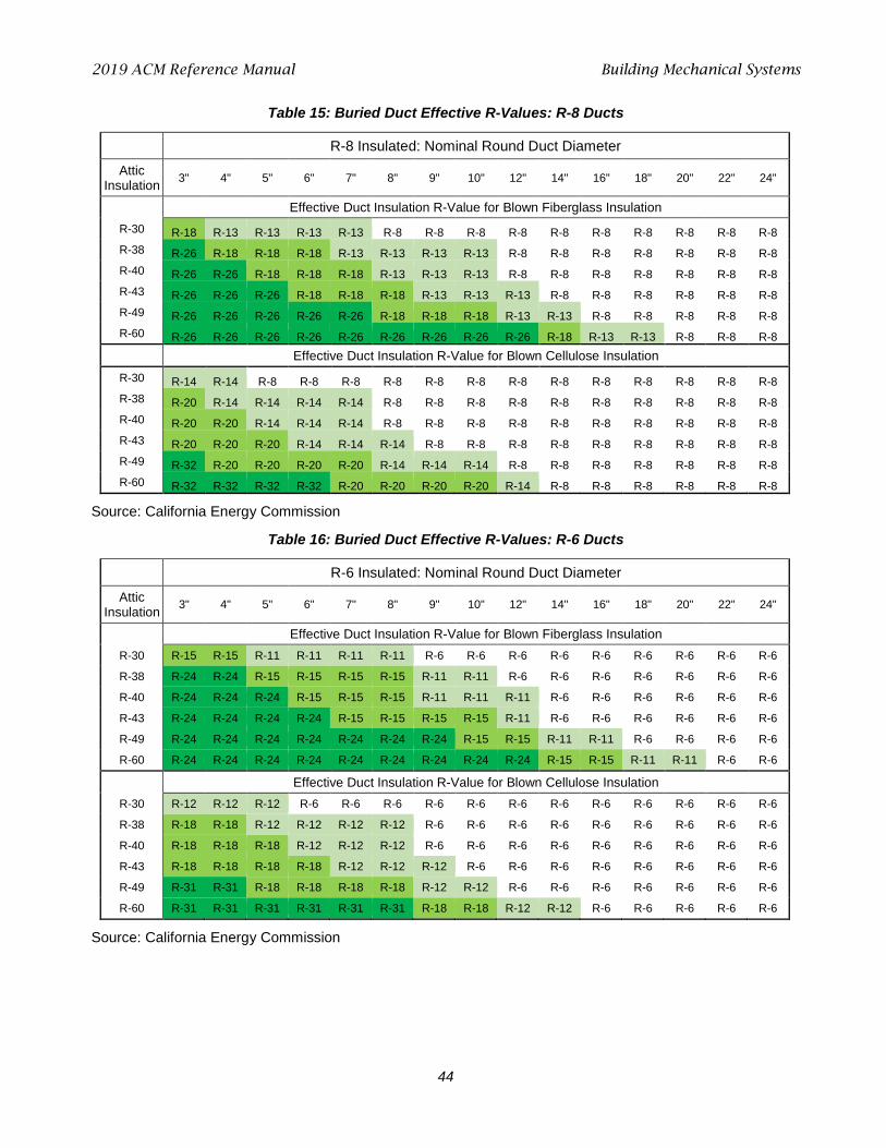
2019 ACM Reference Manual Building Mechanical Systems
44
Table 15: Buried Duct Effective R-Values: R-8 Ducts
R-8 Insulated: Nominal Round Duct Diameter Attic
Insulation 3" 4" 5" 6" 7" 8" 9" 10" 12" 14" 16" 18" 20" 22" 24"
Effective Duct Insulation R-Value for Blown Fiberglass Insulation R-30 R-18 R-13 R-13 R-13 R-13 R-8 R-8 R-8 R-8 R-8 R-8 R-8 R-8 R-8 R-8 R-38 R-26 R-18 R-18 R-18 R-13 R-13 R-13 R-13 R-8 R-8 R-8 R-8 R-8 R-8 R-8 R-40 R-26 R-26 R-18 R-18 R-18 R-13 R-13 R-13 R-8 R-8 R-8 R-8 R-8 R-8 R-8 R-43 R-26 R-26 R-26 R-18 R-18 R-18 R-13 R-13 R-13 R-8 R-8 R-8 R-8 R-8 R-8 R-49 R-26 R-26 R-26 R-26 R-26 R-18 R-18 R-18 R-13 R-13 R-8 R-8 R-8 R-8 R-8 R-60 R-26 R-26 R-26 R-26 R-26 R-26 R-26 R-26 R-26 R-18 R-13 R-13 R-8 R-8 R-8
Effective Duct Insulation R-Value for Blown Cellulose Insulation R-30 R-14 R-14 R-8 R-8 R-8 R-8 R-8 R-8 R-8 R-8 R-8 R-8 R-8 R-8 R-8 R-38 R-20 R-14 R-14 R-14 R-14 R-8 R-8 R-8 R-8 R-8 R-8 R-8 R-8 R-8 R-8 R-40 R-20 R-20 R-14 R-14 R-14 R-8 R-8 R-8 R-8 R-8 R-8 R-8 R-8 R-8 R-8 R-43 R-20 R-20 R-20 R-14 R-14 R-14 R-8 R-8 R-8 R-8 R-8 R-8 R-8 R-8 R-8 R-49 R-32 R-20 R-20 R-20 R-20 R-14 R-14 R-14 R-8 R-8 R-8 R-8 R-8 R-8 R-8 R-60 R-32 R-32 R-32 R-32 R-20 R-20 R-20 R-20 R-14 R-8 R-8 R-8 R-8 R-8 R-8
Source: California Energy Commission
Table 16: Buried Duct Effective R-Values: R-6 Ducts
R-6 Insulated: Nominal Round Duct Diameter Attic
Insulation 3" 4" 5" 6" 7" 8" 9" 10" 12" 14" 16" 18" 20" 22" 24"
Effective Duct Insulation R-Value for Blown Fiberglass Insulation R-30 R-15 R-15 R-11 R-11 R-11 R-11 R-6 R-6 R-6 R-6 R-6 R-6 R-6 R-6 R-6
R-38 R-24 R-24 R-15 R-15 R-15 R-15 R-11 R-11 R-6 R-6 R-6 R-6 R-6 R-6 R-6
R-40 R-24 R-24 R-24 R-15 R-15 R-15 R-11 R-11 R-11 R-6 R-6 R-6 R-6 R-6 R-6
R-43 R-24 R-24 R-24 R-24 R-15 R-15 R-15 R-15 R-11 R-6 R-6 R-6 R-6 R-6 R-6
R-49 R-24 R-24 R-24 R-24 R-24 R-24 R-24 R-15 R-15 R-11 R-11 R-6 R-6 R-6 R-6
R-60 R-24 R-24 R-24 R-24 R-24 R-24 R-24 R-24 R-24 R-15 R-15 R-11 R-11 R-6 R-6
Effective Duct Insulation R-Value for Blown Cellulose Insulation R-30 R-12 R-12 R-12 R-6 R-6 R-6 R-6 R-6 R-6 R-6 R-6 R-6 R-6 R-6 R-6
R-38 R-18 R-18 R-12 R-12 R-12 R-12 R-6 R-6 R-6 R-6 R-6 R-6 R-6 R-6 R-6
R-40 R-18 R-18 R-18 R-12 R-12 R-12 R-6 R-6 R-6 R-6 R-6 R-6 R-6 R-6 R-6
R-43 R-18 R-18 R-18 R-18 R-12 R-12 R-12 R-6 R-6 R-6 R-6 R-6 R-6 R-6 R-6
R-49 R-31 R-31 R-18 R-18 R-18 R-18 R-12 R-12 R-6 R-6 R-6 R-6 R-6 R-6 R-6
R-60 R-31 R-31 R-31 R-31 R-31 R-31 R-18 R-18 R-12 R-12 R-6 R-6 R-6 R-6 R-6
Source: California Energy Commission

2019 ACM Reference Manual Building Mechanical Systems
45
Table 17: Buried Duct Effective R-Values: R-4.2 Ducts
R-4.2 Insulated: Nominal Round Duct Diameter Attic
Insulation 3" 4" 5" 6" 7" 8" 9" 10" 12" 14" 16" 18" 20" 22" 24"
Effective Duct Insulation R-Value for Blown Fiberglass Insulation R-30 R-13 R-13 R-13 R-13 R-9 R-9 R-9 R-4.2 R-4.2 R-4.2 R-4.2 R-4.2 R-4.2 R-4.2 R-4.2
R-38 R-22 R-22 R-22 R-13 R-13 R-13 R-13 R-9 R-9 R-4.2 R-4.2 R-4.2 R-4.2 R-4.2 R-4.2
R-40 R-22 R-22 R-22 R-22 R-13 R-13 R-13 R-13 R-9 R-4.2 R-4.2 R-4.2 R-4.2 R-4.2 R-4.2
R-43 R-22 R-22 R-22 R-22 R-22 R-13 R-13 R-13 R-9 R-9 R-4.2 R-4.2 R-4.2 R-4.2 R-4.2
R-49 R-22 R-22 R-22 R-22 R-22 R-22 R-22 R-22 R-13 R-9 R-9 R-4.2 R-4.2 R-4.2 R-4.2
R-60 R-22 R-22 R-22 R-22 R-22 R-22 R-22 R-22 R-22 R-22 R-13 R-9 R-9 R-4.2 R-4.2
Effective Duct Insulation R-Value for Blown Cellulose Insulation R-30 R-15 R-9 R-9 R-9 R-4.2 R-4.2 R-4.2 R-4.2 R-4.2 R-4.2 R-4.2 R-4.2 R-4.2 R-4.2 R-4.2
R-38 R-15 R-15 R-15 R-9 R-9 R-9 R-9 R-4.2 R-4.2 R-4.2 R-4.2 R-4.2 R-4.2 R-4.2 R-4.2
R-40 R-29 R-15 R-15 R-15 R-9 R-9 R-9 R-9 R-4.2 R-4.2 R-4.2 R-4.2 R-4.2 R-4.2 R-4.2
R-43 R-29 R-15 R-15 R-15 R-15 R-9 R-9 R-9 R-4.2 R-4.2 R-4.2 R-4.2 R-4.2 R-4.2 R-4.2
R-49 R-29 R-29 R-29 R-15 R-15 R-15 R-15 R-9 R-9 R-4.2 R-4.2 R-4.2 R-4.2 R-4.2 R-4.2
R-60 R-29 R-29 R-29 R-29 R-29 R-29 R-15 R-15 R-15 R-9 R-9 R-4.2 R-4.2 R-4.2 R-4.2
Source: California Energy Commission
PROPOSED DESIGN
The software calculates the effective R-value of buried ducts based on user-entered duct size, R-value, and length; attic insulation level and type; and whether the duct meets the requirements of a deeply buried duct by using a lowered ceiling chase or a containment system. This feature must be combined with verified quality insulation installation, verified duct location, reduced surface area and R-value, and verified minimum airflow. The software will allow any combination of duct runs and the associated buried condition, and the overall duct system effective R-value will be a weighted average of the combination. The default is no buried ducts.
STANDARD DESIGN
The standard design has no buried ducts.
VERIFICATION AND REPORTING
Buried duct credit is reported in the HERS required verification listing on the CF1R.
Duct/Air Handler Leakage
The total duct/air handler leakage shown in Table 18 is used in simulating the duct system. The supply duct leakage for each case is the table value times 0.585. The return leakage is the table value times 0.415.
PROPOSED DESIGN
For each ducted system, the software user specifies one of the duct/air handler leakage cases shown in Table 18.

2019 ACM Reference Manual Building Mechanical Systems
46
STANDARD DESIGN
For ducted systems, the standard design is sealed and tested duct systems in existing dwelling units or new duct systems.
VERIFICATION AND REPORTING
Sealed and tested duct systems are listed in the HERS verification section of the CF1R. Duct leakage is measured in accordance with procedures and values specified in Reference Appendices, Residential Appendix RA3.
Low Leakage Air Handlers
A low-leakage air handler may be specified as well as a lower duct leakage value (see Section 2.4.6.11). Installation requires installing one of the list of approved low-leakage air handling units published by the Energy Commission. The manufacturer certifies that the appliance complies with the requirements of Reference Joint Appendices 9.2.1, 9.2.2, 9.2.3, and 9.2.4.
Table 18: Duct/Air Handler Leakage
Case Duct Leakage Air Handler Leakage Total Duct/Air Handler Leakage
Duct systems in existing single-family houses
15% Included in duct leakage
15%
Sealed and tested new or altered duct systems in unconditioned or conditioned space in a multifamily dwelling unit
12% Included in duct leakage
12%
Sealed and tested new or altered duct systems in unconditioned or conditioned space in a townhome or single-family home
5% 2% 7%
Verified low-leakage ducts in conditioned space
0% 0% 0%
Low leakage air handlers in combination with sealed and tested new duct systems
5% or as measured 0% 5% or as measured
Source: California Energy Commission
PROPOSED DESIGN
Credit can be taken for installing a factory-sealed air-handling unit tested by the manufacturer and certified to the Energy Commission to meet the requirements for a low-leakage air-handler. Field verification of the air handler model number is required.
2019 ACM Reference Manual Building Mechanical Systems
47
STANDARD DESIGN
The standard design has a normal air handler.
VERIFICATION AND REPORTING
A low-leakage air handler is reported on the compliance report and field verified in accordance with the procedures specified in Reference Appendices, Residential Appendix RA3.1.4.3.9.
Verified Low-Leakage Ducts in Conditioned Space
PROPOSED DESIGN
For ducted systems, the user may specify that all ducts are entirely in conditioned space, and the software will model the duct system with no leakage and no conduction losses.
STANDARD DESIGN
The standard design has ducts in the default location.
VERIFICATION AND REPORTING
Systems that have all ducts entirely in conditioned space are reported on the compliance documents, and this is verified by measurements showing duct leakage to outside conditions is equal to or less than 25 CFM when measured in accordance with Reference Appendices, Residential Appendix RA3.
2.4.7 Space-Conditioning Fan Subsystems
Fan systems move air for air-conditioning, heating, and ventilation systems. The software allows the user to define the fans to be used for space-conditioning, indoor air quality, and ventilation cooling. Indoor air quality and ventilation cooling are discussed in Sections 2.4.9 and 2.4.10.
PROPOSED DESIGN
For the space-conditioning fan system, the user selects the type of equipment and enters basic information to model the energy use of the equipment. For ducted central air-conditioning and heating systems, the fan efficacy default is the mandatory minimum verified efficacy of 0.45, 0.58, or 0.62 W/CFM, depending on applicable system type (also assumed when there is no cooling system).
STANDARD DESIGN
The standard design fan shall meet the minimum Section 150.1(c) and Table 150.1-A or 150.1-B requirements.
VERIFICATION AND REPORTING
Minimum verified fan efficacy is mandatory for all ducted cooling systems. Fan efficacy is reported in the HERS required verification listings on the CF1R.
2019 ACM Reference Manual Building Mechanical Systems
48
2.4.8 Space-Conditioning Systems
This section describes the general procedures for heating and cooling systems in low-rise residential buildings. The system includes the cooling system, the heating system, distribution system, and mechanical fans.
If multiple systems serve a building, each system and the conditioned space it serves may be modeled in detail separately or the systems may be aggregated and modeled as one large system. If the systems are aggregated, they must be the same type and all meet the same minimum specifications.
Multiple System Types Within Dwelling
PROPOSED DESIGN
For proposed designs using more than one heating system type, equipment type, or fuel type, and the types do not serve the same floor area, the user shall zone the building by system type.
STANDARD DESIGN
The standard design shall have the same zoning and heating system types as the proposed design.
VERIFICATION AND REPORTING
The heating system type of each zone is shown on the CF1R.
Multiple Systems Serving Same Area
If a space or a zone is served by more than one heating system, compliance is demonstrated with the most time-dependent valuation (TDV) energy-consuming system serving the space or the zone. For spaces or zones that are served by electric resistance heat in addition to other heating systems, the electric resistance heat is deemed the most TDV energy-consuming system unless the supplemental heating meets the exception to Section 150.1(c)6. See eligibility criteria in Residential Compliance Manual Section 4.2.2 for conditions under which the supplemental heat may be ignored.
For floor areas served by more than one cooling system, equipment, or fuel type, the system, equipment, and fuel type that satisfy the cooling load are modeled.
No Cooling
PROPOSED DESIGN
When the proposed design has no cooling system, the proposed design is required to model the standard design cooling system defined in Section 150.1(c) and Table 150.1-A or 150.1-B. Since the proposed design system is identical to the standard design system, there is no penalty or credit.
STANDARD DESIGN
The standard design system is the specified in Section 150.1(c) and Table 150.1-A or 150.1-B for the applicable climate zone.
VERIFICATION AND REPORTING
No cooling is reported as a special feature on the CF1R.

2019 ACM Reference Manual Building Mechanical Systems
49
Zonally Controlled Forced-Air Cooling Systems
Zonally controlled central forced-air cooling systems must be able to deliver, in every zonal control mode, an airflow to the dwelling of > 350 CFM per ton of nominal cooling capacity, and operating at an air-handling unit fan efficacy of < 0.45 or 0.58 W/CFM depending on the applicable system type. This is a HERS-verified measure, complying with Residential Appendix RA3.3.
An exception allows multispeed or variable-speed compressor systems, or single-speed compressor systems to meet the mandatory airflow (CFM/ton) and fan efficacy (watt/CFM) requirements by operating the system at maximum compressor capacity, and system fan speed with all zones calling for conditioning, rather than in every zonal control mode.
PROPOSED DESIGN
The user selects zonally controlled as a cooling system input.
STANDARD DESIGN
The standard design building does not have a zonally controlled cooling system.
VERIFICATION AND REPORTING
Zonally controlled forced-air cooling systems are required to have the system bypass duct status verified by a HERS rater according to the procedures in Reference Residential Appendix RA3.1.4.6, and the fan efficacy and airflow rate are required to be verified according to the procedures in RA3.3.
2.4.9 Indoor Air Quality Ventilation
The standards include a mandatory requirement for mechanical ventilation to provide acceptable indoor air quality for all newly constructed buildings and additions greater than 1,000 square feet. ASHRAE Standard 62.2-2016 as published in the 2017 supplement except Addendum k.
Amendments to ASHRAE 62.2:
Single-family homes use a default envelope leakage value of 2 ACH50 in place of a blower door measurement in section 4.1 of ASHRAE 62.2.
For single-family and multifamily dwelling units, increase filter efficiency in section 6.7 of ASHRAE 62.2 from MERV 6 to MERV 13.
For multifamily dwelling units, require sealing of the dwelling unit enclosures and enforce a HERS-verified maximum allowable leakage rate of 0.3 cfm/ft2 of enclosure area when unbalanced system types (exhaust, or supply) are used.
For estimating the energy impact of this requirement in compliance software, the minimum ventilation rate is met by either a standalone indoor air quality (IAQ) fan system or a central air handler fan system that can introduce outdoor air. In many cases, this energy is substantially compliance-neutral because the standard design is typically set equal to the proposed design.
The simplest IAQ fan system is an exhaust fan/bathroom fan that meets the criteria in ASHRAE Standard 62.2 for air delivery and minimal noise. More advanced IAQ fan systems that have a supply or both supply and exhaust fans are possible. To calculate the energy use of standalone IAQ fan systems, the systems are assumed to be on continuously.
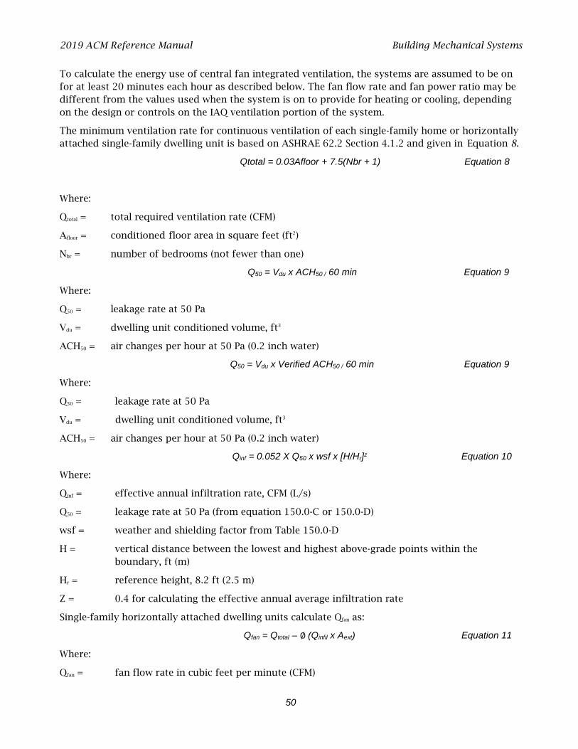
2019 ACM Reference Manual Building Mechanical Systems
50
To calculate the energy use of central fan integrated ventilation, the systems are assumed to be on for at least 20 minutes each hour as described below. The fan flow rate and fan power ratio may be different from the values used when the system is on to provide for heating or cooling, depending on the design or controls on the IAQ ventilation portion of the system.
The minimum ventilation rate for continuous ventilation of each single-family home or horizontally attached single-family dwelling unit is based on ASHRAE 62.2 Section 4.1.2 and given in Equation 8.
Qtotal = 0.03Afloor + 7.5(Nbr + 1) Equation 8
Where:
Qtotal = total required ventilation rate (CFM)
Afloor = conditioned floor area in square feet (ft2)
Nbr = number of bedrooms (not fewer than one)
Q50 = Vdu x ACH50 / 60 min Equation 9
Where:
Q50 = leakage rate at 50 Pa
Vdu = dwelling unit conditioned volume, ft3
ACH50 = air changes per hour at 50 Pa (0.2 inch water)
Q50 = Vdu x Verified ACH50 / 60 min Equation 9
Where:
Q50 = leakage rate at 50 Pa
Vdu = dwelling unit conditioned volume, ft3
ACH50 = air changes per hour at 50 Pa (0.2 inch water)
Qinf = 0.052 X Q50 x wsf x [H/Hr]z Equation 10
Where:
Qinf = effective annual infiltration rate, CFM (L/s)
Q50 = leakage rate at 50 Pa (from equation 150.0-C or 150.0-D)
wsf = weather and shielding factor from Table 150.0-D
H = vertical distance between the lowest and highest above-grade points within the boundary, ft (m)
Hr = reference height, 8.2 ft (2.5 m)
Z = 0.4 for calculating the effective annual average infiltration rate
Single-family horizontally attached dwelling units calculate Qfan as:
Qfan = Qtotal – ∅ (Qinfil x Aext) Equation 11
Where:
Qfan = fan flow rate in cubic feet per minute (CFM)
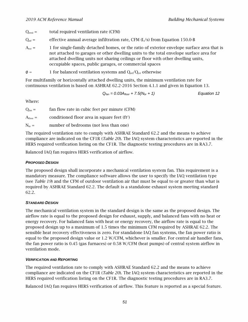
2019 ACM Reference Manual Building Mechanical Systems
51
Qtotal = total required ventilation rate (CFM)
Qinf = effective annual average infiltration rate, CFM (L/s) from Equation 150.0-B
Aext = 1 for single-family detached homes, or the ratio of exterior envelope surface area that is not attached to garages or other dwelling units to the total envelope surface area for attached dwelling units not sharing ceilings or floor with other dwelling units, occupiable spaces, public garages, or commercial spaces
∅ = 1 for balanced ventilation systems and Qinf/Qtot otherwise
For multifamily or horizontally attached dwelling units, the minimum ventilation rate for continuous ventilation is based on ASHRAE 62.2-2016 Section 4.1.1 and given in Equation 13.
Qfan = 0.03Afloor + 7.5(Nbr + 1) Equation 12
Where:
Qfan = fan flow rate in cubic feet per minute (CFM)
Afloor = conditioned floor area in square feet (ft2)
Nbr = number of bedrooms (not less than one)
The required ventilation rate to comply with ASHRAE Standard 62.2 and the means to achieve compliance are indicated on the CF1R (Table 20). The IAQ system characteristics are reported in the HERS required verification listing on the CF1R. The diagnostic testing procedures are in RA3.7.
Balanced IAQ fan requires HERS verification of airflow.
PROPOSED DESIGN
The proposed design shall incorporate a mechanical ventilation system fan. This requirement is a mandatory measure. The compliance software allows the user to specify the IAQ ventilation type (see Table 19) and the CFM of outdoor ventilation air that must be equal to or greater than what is required by ASHRAE Standard 62.2. The default is a standalone exhaust system meeting standard 62.2.
STANDARD DESIGN
The mechanical ventilation system in the standard design is the same as the proposed design. The airflow rate is equal to the proposed design for exhaust, supply, and balanced fans with no heat or energy recovery. For balanced fans with heat or energy recovery, the airflow rate is equal to the proposed design up to a maximum of 1.5 times the minimum CFM required by ASHRAE 62.2. The sensible heat recovery effectiveness is zero. For standalone IAQ fan systems, the fan power ratio is equal to the proposed design value or 1.2 W/CFM, whichever is smaller. For central air handler fans, the fan power ratio is 0.45 (gas furnaces) or 0.58 W/CFM (heat pumps) of central system airflow in ventilation mode.
VERIFICATION AND REPORTING
The required ventilation rate to comply with ASHRAE Standard 62.2 and the means to achieve compliance are indicated on the CF1R (Table 20). The IAQ system characteristics are reported in the HERS required verification listing on the CF1R. The diagnostic testing procedures are in RA3.7.
Balanced IAQ fan requires HERS verification of airflow. This feature is reported as a special feature.
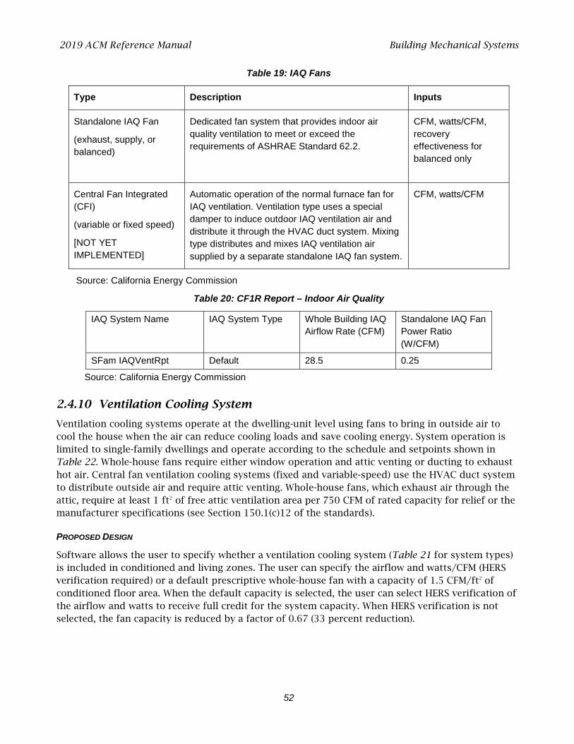
2019 ACM Reference Manual Building Mechanical Systems
52
Table 19: IAQ Fans
Type Description Inputs
Standalone IAQ Fan
(exhaust, supply, or balanced)
Dedicated fan system that provides indoor air quality ventilation to meet or exceed the requirements of ASHRAE Standard 62.2.
CFM, watts/CFM, recovery effectiveness for balanced only
Central Fan Integrated (CFI)
(variable or fixed speed)
[NOT YET IMPLEMENTED]
Automatic operation of the normal furnace fan for IAQ ventilation. Ventilation type uses a special damper to induce outdoor IAQ ventilation air and distribute it through the HVAC duct system. Mixing type distributes and mixes IAQ ventilation air supplied by a separate standalone IAQ fan system.
CFM, watts/CFM
Source: California Energy Commission
Table 20: CF1R Report – Indoor Air Quality
IAQ System Name IAQ System Type Whole Building IAQ Airflow Rate (CFM)
Standalone IAQ Fan Power Ratio (W/CFM)
SFam IAQVentRpt Default 28.5 0.25
Source: California Energy Commission
2.4.10 Ventilation Cooling System
Ventilation cooling systems operate at the dwelling-unit level using fans to bring in outside air to cool the house when the air can reduce cooling loads and save cooling energy. System operation is limited to single-family dwellings and operate according to the schedule and setpoints shown in Table 22. Whole-house fans require either window operation and attic venting or ducting to exhaust hot air. Central fan ventilation cooling systems (fixed and variable-speed) use the HVAC duct system to distribute outside air and require attic venting. Whole-house fans, which exhaust air through the attic, require at least 1 ft2 of free attic ventilation area per 750 CFM of rated capacity for relief or the manufacturer specifications (see Section 150.1(c)12 of the standards).
PROPOSED DESIGN
Software allows the user to specify whether a ventilation cooling system (Table 21 for system types) is included in conditioned and living zones. The user can specify the airflow and watts/CFM (HERS verification required) or a default prescriptive whole-house fan with a capacity of 1.5 CFM/ft2 of conditioned floor area. When the default capacity is selected, the user can select HERS verification of the airflow and watts to receive full credit for the system capacity. When HERS verification is not selected, the fan capacity is reduced by a factor of 0.67 (33 percent reduction).
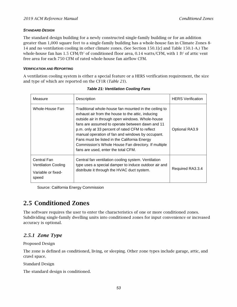
2019 ACM Reference Manual Conditioned Zones
53
STANDARD DESIGN
The standard design building for a newly constructed single-family building or for an addition greater than 1,000 square feet to a single-family building has a whole-house fan in Climate Zones 8-14 and no ventilation cooling in other climate zones. (See Section 150.1[c] and Table 150.1-A.) The whole-house fan has 1.5 CFM/ft2 of conditioned floor area, 0.14 watts/CFM, with 1 ft2 of attic vent free area for each 750 CFM of rated whole-house fan airflow CFM.
VERIFICATION AND REPORTING
A ventilation cooling system is either a special feature or a HERS verification requirement, the size and type of which are reported on the CF1R (Table 21).
Table 21: Ventilation Cooling Fans
Measure Description HERS Verification
Whole-House Fan Traditional whole-house fan mounted in the ceiling to exhaust air from the house to the attic, inducing outside air in through open windows. Whole-house fans are assumed to operate between dawn and 11 p.m. only at 33 percent of rated CFM to reflect manual operation of fan and windows by occupant. Fans must be listed in the California Energy Commission’s Whole House Fan directory. If multiple fans are used, enter the total CFM.
Optional RA3.9
Central Fan Ventilation Cooling
Variable or fixed-speed
Central fan ventilation cooling system. Ventilation type uses a special damper to induce outdoor air and distribute it through the HVAC duct system. Required RA3.3.4
Source: California Energy Commission
2.5 Conditioned Zones
The software requires the user to enter the characteristics of one or more conditioned zones. Subdividing single-family dwelling units into conditioned zones for input convenience or increased accuracy is optional.
2.5.1 Zone Type
Proposed Design
The zone is defined as conditioned, living, or sleeping. Other zone types include garage, attic, and crawl space.
Standard Design
The standard design is conditioned.

2019 ACM Reference Manual Conditioned Zones
54
VERIFICATION AND REPORTING
When the zone type is living or sleeping, this is reported as a special feature on the CF1R.
Heating Zonal Control Credit
With the heating zonal control credit, the sleeping and living areas are modeled separately for heating, each with its own separate thermostat schedule and internal gain assumptions. Zonal control cannot be modeled with heat pump heating. The total nonclosable opening area between zones cannot exceed 40 ft2. Other eligibility criteria for this measure are presented in the Residential Compliance Manual, Chapter 4.
PROPOSED DESIGN
The user selects zonal control as a building level input with separate living and sleeping zones.
STANDARD DESIGN
The standard design building is not zoned for living and sleeping separately.
VERIFICATION AND REPORTING
Zonal control is reported as a special feature on the CF1R.
2.5.2 Conditioned Floor Area
The total conditioned floor area (CFA) is the raised floor as well as the slab-on-grade floor area of the conditioned spaces measured from the exterior surface of exterior walls. Stairs are included in conditioned floor area as the area beneath the stairs and the tread of the stairs.
PROPOSED DESIGN
The compliance software requires the user to enter the total conditioned floor area of each conditioned zone.
STANDARD DESIGN
The standard design building has the same conditioned floor area and same conditioned zones as the proposed design.
VERIFICATION AND REPORTING
The conditioned floor area of each conditioned zone is reported on the CF1R.
2.5.3 Number of Stories
Number of Stories of the Zone
PROPOSED DESIGN
The number of stories of the zone.
STANDARD DESIGN
The standard design is the same as the proposed design.

2019 ACM Reference Manual Conditioned Zones
55
Ceiling Height
PROPOSED DESIGN
The average ceiling height of the proposed design is the conditioned volume of the building envelope. The volume (in cubic feet) is determined from the total conditioned floor area and the average ceiling height.
STANDARD DESIGN
The volume of the standard design building is the same as the proposed design.
VERIFICATION AND REPORTING
The conditioned volume of each zone is reported on the CF1R.
Free Ventilation Area
Free ventilation area is the window area adjusted to account for bug screens, window framing and dividers, and other factors.
PROPOSED DESIGN
Free ventilation area for the proposed design is calculated as 5 percent of the fenestration area (rough opening), assuming all windows are operable.
STANDARD DESIGN
The standard design value for free ventilation area is the same as the proposed design.
VERIFICATION AND REPORTING
Free ventilation is not reported on the CF1R.
Ventilation Height Difference
Ventilation height difference is not a user input.
PROPOSED DESIGN
The default assumption for the proposed design is 2 feet for one-story buildings or one-story dwelling units and 8 feet for two or more stories (as derived from number of stories and other zone details).
STANDARD DESIGN
The standard design modeling assumption for the elevation difference between the inlet and the outlet is 2 feet for one-story dwelling units and 8 feet for two or more stories.
Zone Elevations
The elevation of the top and bottom of each zone is required to set up the airflow network.
2019 ACM Reference Manual Conditioned Zones
56
PROPOSED DESIGN
The user enters the height of the top surface the lowest floor of the zone relative to the ground outside as the “bottom” of the zone. The user also enters the ceiling height (the floor-to-floor height [ceiling height plus the thickness of the intermediate floor structure] is calculated by the software).
Underground zones are indicated with the number of feet below grade (for example, -8).
STANDARD DESIGN
The standard design has the same vertical zone dimensions as the proposed design.
Mechanical Systems
PROPOSED DESIGN
The software requires the user to specify a previously defined HVAC system to provide heating and cooling for the zone and an indoor air quality (IAQ) ventilation system. The user may also specify a ventilation cooling system that applies to this and other conditioned zones.
STANDARD DESIGN
The software assigns standard design HVAC, IAQ ventilation, and ventilation cooling systems based on Section 150.1(c) and Table 150.1-A or 150.1-B for the applicable climate zone.
Natural Ventilation
Natural ventilation (from windows) is available during cooling mode when needed and available, as shown in Table 22. The amount of natural ventilation used by computer software for natural cooling is the lesser of the maximum potential amount available and the amount needed to drive the interior zone temperature down to the natural cooling setpoint. When natural cooling is not needed or is unavailable, no natural ventilation is used.
Computer software shall assume that natural cooling is needed when the building is in “cooling mode,” when the outside temperature is below the estimated zone temperature, and when the estimated zone temperature is above the natural cooling setpoint temperature. Only the amount of ventilation required to reduce the zone temperature to the natural ventilation setpoint temperature is used, and the natural ventilation setpoint temperature is constrained by the compliance software to be greater than the heating setpoint temperature.
2.5.4 Conditioned Zone Assumptions
Internal Thermal mass
Internal mass objects are completely inside a zone so that they do not participate directly in heat flows to other zones or outside. They are connected to the zone radiantly and convectively and participate in the zone energy balance by passively storing and releasing heat as conditions change.
Table 23 shows the standard interior conditioned zone thermal mass objects and the calculation of the simulation inputs that represent them.
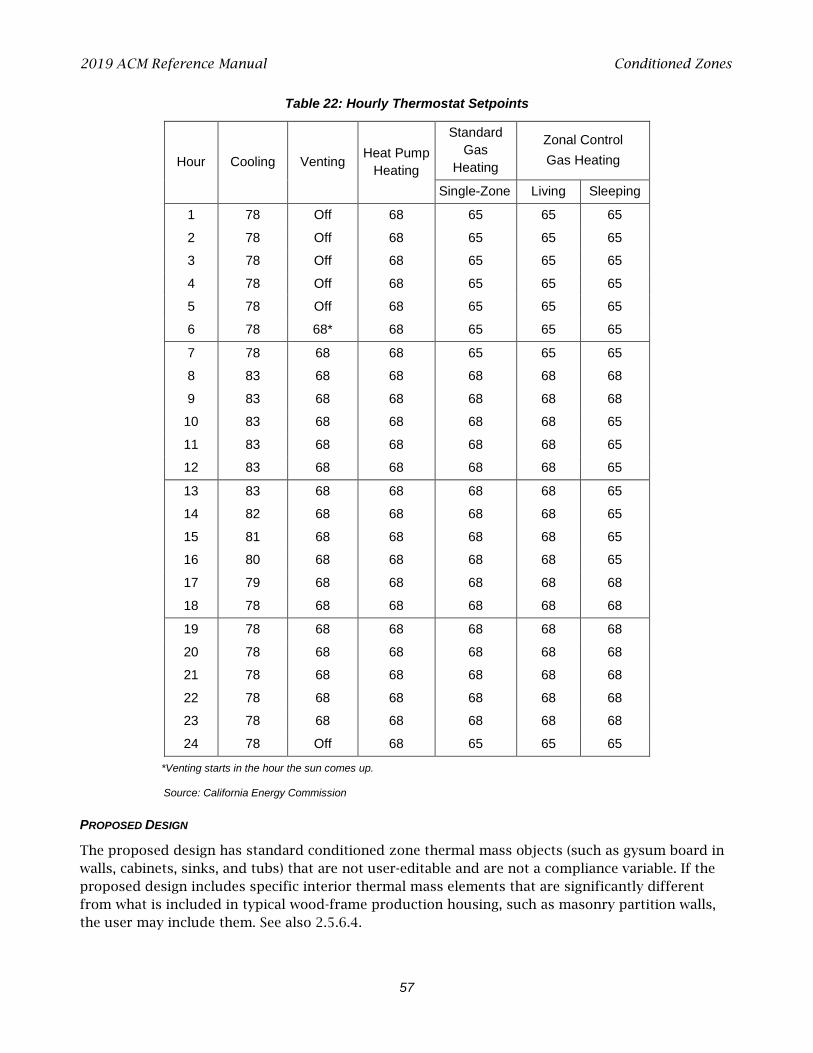
2019 ACM Reference Manual Conditioned Zones
57
Table 22: Hourly Thermostat Setpoints
Hour Cooling Venting Heat Pump Heating
Standard Gas
Heating
Zonal Control Gas Heating
Single-Zone Living Sleeping
1 78 Off 68 65 65 65
2 78 Off 68 65 65 65
3 78 Off 68 65 65 65
4 78 Off 68 65 65 65
5 78 Off 68 65 65 65
6 78 68* 68 65 65 65
7 78 68 68 65 65 65
8 83 68 68 68 68 68
9 83 68 68 68 68 68
10 83 68 68 68 68 65
11 83 68 68 68 68 65
12 83 68 68 68 68 65
13 83 68 68 68 68 65
14 82 68 68 68 68 65
15 81 68 68 68 68 65
16 80 68 68 68 68 65
17 79 68 68 68 68 68
18 78 68 68 68 68 68
19 78 68 68 68 68 68
20 78 68 68 68 68 68
21 78 68 68 68 68 68
22 78 68 68 68 68 68
23 78 68 68 68 68 68
24 78 Off 68 65 65 65
*Venting starts in the hour the sun comes up.
Source: California Energy Commission
PROPOSED DESIGN
The proposed design has standard conditioned zone thermal mass objects (such as gysum board in walls, cabinets, sinks, and tubs) that are not user-editable and are not a compliance variable. If the proposed design includes specific interior thermal mass elements that are significantly different from what is included in typical wood-frame production housing, such as masonry partition walls, the user may include them. See also 2.5.6.4.
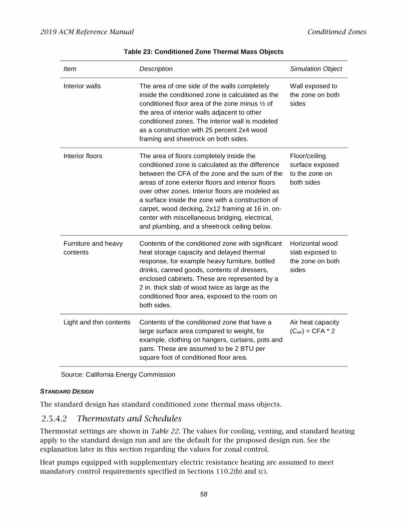
2019 ACM Reference Manual Conditioned Zones
58
Table 23: Conditioned Zone Thermal Mass Objects
Item Description Simulation Object
Interior walls The area of one side of the walls completely inside the conditioned zone is calculated as the conditioned floor area of the zone minus ½ of the area of interior walls adjacent to other conditioned zones. The interior wall is modeled as a construction with 25 percent 2x4 wood framing and sheetrock on both sides.
Wall exposed to the zone on both sides
Interior floors The area of floors completely inside the conditioned zone is calculated as the difference between the CFA of the zone and the sum of the areas of zone exterior floors and interior floors over other zones. Interior floors are modeled as a surface inside the zone with a construction of carpet, wood decking, 2x12 framing at 16 in. on-center with miscellaneous bridging, electrical, and plumbing, and a sheetrock ceiling below.
Floor/ceiling surface exposed to the zone on both sides
Furniture and heavy contents
Contents of the conditioned zone with significant heat storage capacity and delayed thermal response, for example heavy furniture, bottled drinks, canned goods, contents of dressers, enclosed cabinets. These are represented by a 2 in. thick slab of wood twice as large as the conditioned floor area, exposed to the room on both sides.
Horizontal wood slab exposed to the zone on both sides
Light and thin contents Contents of the conditioned zone that have a large surface area compared to weight, for example, clothing on hangers, curtains, pots and pans. These are assumed to be 2 BTU per square foot of conditioned floor area.
Air heat capacity (Cair) = CFA * 2
Source: California Energy Commission
STANDARD DESIGN
The standard design has standard conditioned zone thermal mass objects.
Thermostats and Schedules
Thermostat settings are shown in Table 22. The values for cooling, venting, and standard heating apply to the standard design run and are the default for the proposed design run. See the explanation later in this section regarding the values for zonal control.
Heat pumps equipped with supplementary electric resistance heating are assumed to meet mandatory control requirements specified in Sections 110.2(b) and (c).
2019 ACM Reference Manual Conditioned Zones
59
Systems with no setback required by Section 110.2(c) (gravity gas wall heaters, gravity floor heaters, gravity room heaters, noncentral electric heaters, fireplaces or decorative gas appliances, wood stoves, room air-conditioners, and room air-conditioner heat pumps) are assumed to have a constant heating set point of 68 degrees. The cooling set point from Table 22 is assumed in both the proposed design and standard design.
PROPOSED DESIGN
The proposed design assumes a mandatory setback thermostat meeting the requirements of Section 110.2(c). Systems exempt from the requirement for a setback thermostat are assumed to have no setback capabilities.
STANDARD DESIGN
The standard design has setback thermostat conditions based on the mandatory requirement for a setback thermostat. For equipment exempt from the setback thermostat requirement, the standard design has no setback thermostat capabilities.
Determining Heating Mode vs. Cooling Mode
When the building is in the heating mode, the heating setpoints for each hour are set to the “heating” values in Table 22, the cooling setpoint is a constant 78°F, and the ventilation setpoint is set to a constant 77°F. When the building is in the cooling mode, the heating setpoint is a constant 60°F, and the cooling and venting setpoints are set to the values in Table 22.
The mode depends upon the outdoor temperature averaged over hours 1 through 24 of eight days prior to the current day through two days prior to the current day. (For example, if the current day is June 21, the mode is based on the average temperature for June 13 through 20.) When this running average temperature is equal to or less than 60°F, the building is in a heating mode. When the running average is greater than 60°F, the building is in a cooling mode.
2.5.5 Internal Gains
Internal gains assumptions are included in Appendix E and consistent with the CASE report on plug loads and lighting (Rubin 2019, see Appendix F).
2.5.6 Exterior Surfaces
The user enters exterior surfaces to define the envelope of the proposed design. The areas, construction assemblies, orientations, and tilts modeled are consistent with the actual building design and shall equal the overall roof/ceiling area with conditioned space on the inside and unconditioned space on the other side.
Ceilings Below Attics
Ceilings below attics are horizontal surfaces between conditioned zones and attics. The area of the attic floor is determined by the total area of ceilings below attics defined in conditioned zones.
PROPOSED DESIGN
The software allows the user to define ceilings below attic, enter the area, and select a construction assembly for each.
2019 ACM Reference Manual Conditioned Zones
60
STANDARD DESIGN
The standard design for new construction has the same ceiling below attic area as the proposed design. The standard design is a high-performance attic with a ceiling constructed with 2x4 framed trusses and insulated with the R-values specified in Section 150.1(c) and Table 150.1-A or 150.1-B for the applicable climate zone, assuming Option B. The roof surface is a 10 lbs/ft2 tile roof with an air space when the proposed roof is steep slope or a lightweight roof when the proposed roof is low slope.
Single-family dwelling units: Below-roof-deck insulation has R-0 in Climate Zones 1-3 and 5-7 and R-19 in Climate Zones 4 and 8-16. Insulation on the ceiling has R-38 in Climate Zones 1, 2, 4, and 8-16 and R-30 insulation in Climate Zones 3 and 5-7. Climate Zones 2, 3, and 5-7 have a radiant barrier, and Climate Zones 1, 4, and 8-16 have no radiant barrier.
Multifamily dwelling units: Below-roof-deck insulation has R-0 in Climate Zones 1-3 and 5-7, R-13 in Climate Zones 10 and 16, and R-19 in Climate Zones 4, 8, 9 and 11-15. Insulation on the ceiling has R-38 in Climate Zones 1, 2, 4, and 8-16, and R-30 insulation on the ceiling in Climate Zones 3 and 5-7. Climate Zones 2, 3, and 5-7 have a radiant barrier, and Climate Zones 1, 4, and 8-16 have no radiant barrier.
VERIFICATION AND REPORTING
Ceiling below attic area and constructions are reported on the CF1R. Metal-framed and SIP assemblies are reported as a special feature on the CF1R.
Non-Attic (Cathedral) Ceiling and Roof
Nonattic ceilings, also known as cathedral ceilings, are surfaces with roofing on the outside and finished ceiling on the inside but without an attic space.
PROPOSED DESIGN
The software allows the user to define cathedral ceilings, enter the area, and select a construction assembly for each. The user also enters the roof characteristics of the surface.
STANDARD DESIGN
The standard design has the same area as the proposed design cathedral ceiling modeled as ceiling below attic with the features of Option B from Section 150.1(c) and Table 150.1-A or 150.1-B for the applicable climate zone.
The standard design building has an area of ceiling below attic equal to the nonattic ceiling/roof areas of the proposed design. The standard design roof and ceiling surfaces are modeled with the same construction assembly and characteristics, aged reflectance and emittance as Section 150.1(c), Table 150.1-A or 150.1-B for the applicable climate zone.
VERIFICATION AND REPORTING
Non-attic ceiling/roof area and constructions are reported on the CF1R. Metal frame and SIP assemblies are reported as a special feature on the CF1R.
2019 ACM Reference Manual Conditioned Zones
61
Exterior Walls
PROPOSED DESIGN
The software allows the user to define walls, enter the gross area, and select a construction assembly for each. The user also enters the plan orientation (front, left, back, or right) or plan azimuth (value relative to the front, which is represented as zero degrees) and tilt of the wall.
The wall areas modeled are consistent with the actual building design, and the total wall area is equal to the gross wall area with conditioned space on the inside and unconditioned space or exterior conditions on the other side. Underground mass walls are defined with inside and outside insulation and the number of feet below grade. Walls adjacent to unconditioned spaces with no solar gains (such as knee walls or garage walls) are entered as an interior wall with the zone on the other side specified as attic, garage, or another zone, and the compliance manager treats that wall as a demising wall. An attached unconditioned space is modeled as an unconditioned zone.
STANDARD DESIGN
The standard design building has high-performance walls modeled with the same area of framed walls as is in the proposed design separating conditioned space and the exterior, with a U-factor equivalent to that as specified in Section 150.1(c)1.B and Table 150.1-A or 150.1-B for the applicable climate zone.
Single-family dwellings: Above-grade framed walls in Climate Zones 1-5 and 8-16 have 2 x 6 16-in. on center wood framing with R-21 insulation between framing and R-5 continuous insulation (0.048 U-factor). Climate Zones 6-7 above-grade walls have 2 x 4 16-in. on center wood framing with R-15 insulation between framing and R-4 continuous insulation (0.065 U-factor). Walls adjacent to unconditioned space, such as garage walls, are treated the same as exterior walls, except there is no continuous insulation.
Multifamily dwellings: Above-grade framed walls in Climate Zones 1-5 and 8-16 have 2 x 6 16-in. on center wood framing with R-21 insulation between framing and R-4 continuous insulation (0.051 U-factor). Climate Zones 6-7 above-grade framed walls have 2 x 4 16-in. on center wood framing with R-15 insulation between framing and R-4 continuous insulation (0.065 U-factor). Walls adjacent to unconditioned space, such as garage walls, are treated the same as exterior walls, except there is no continuous insulation.
Standard design mass wall requirements are the same for single and multifamily buildings. Above-grade mass walls are 6-inch concrete with R-13 interior insulation in 3.5-inch wood furring in Climate Zones 1-15 and R-17 in Climate Zone 16. Below-grade mass walls in Climate Zones 1-15 have R-13, and Climate Zone 16 has R-15 interior insulation in 3.5-inch wood furring. When the proposed design is a wall type such as SIP, straw bale, or other construction type not specifically mentioned above, the standard design wall is a wood-framed wall meeting the requirements of Section 150.1(c) Table 150.1-A or 150.1-B.
The total gross exterior wall area in the standard design is equal to the total gross exterior wall area of the proposed design for each wall type. The gross exterior wall area of framed walls in the standard design (excluding demising walls) is equally divided among the four main compass points -- north, east, south, and west. The gross exterior wall area of mass walls in the standard design (excluding demising walls and below grade walls) is equally divided among these four main compass points. Window and door areas are subtracted from the gross wall area to determine the net wall area in each orientation.

2019 ACM Reference Manual Conditioned Zones
62
VERIFICATION AND REPORTING
Exterior wall area and construction details are reported on the CF1R. Metal-framed and SIP assemblies are reported as a special feature on the CF1R.
Exterior Thermal Mass
Constructions for standard exterior mass are supported but not implemented beyond the assumptions for typical mass.
The performance approach assumes that both the proposed design and standard design building have a minimum mass as a function of the conditioned area of slab floor and nonslab floor. (See Section 2.5.4.1.)
Mass such as concrete slab floors, masonry walls, double gypsum board, and other special mass elements can be modeled. When the proposed design has more than the typical assumptions for mass in a building, then each element of heavy mass is modeled in the proposed design, otherwise; the proposed design is modeled with the same thermal mass as the standard design.
PROPOSED DESIGN
The proposed design may be modeled with the default 20 percent exposed mass/80 percent covered mass or with actual mass areas modeled as separate covered and exposed mass surfaces. Exposed mass surfaces covered with flooring material that is in direct contact with the slab can be modeled as exposed mass. Examples of such materials are tile, stone, vinyl, linoleum, and hard-wood.
STANDARD DESIGN
The conditioned slab floor in the standard design is assumed to be 20 percent exposed slab and 80 percent slab covered by carpet or casework. Interior mass assumptions as described in Section 2.5.4.1 are also assumed. No other mass elements are modeled in the standard design. The standard design mass is modeled with the following characteristics:
• The conditioned slab floor area (slab area) shall have a thickness of 3.5 inches, a volumetric heat capacity of 28 Btu/ft3-°F, and a conductivity of 0.98 Btu-in/hr-ft2-°F. The exposed portion shall have a surface conductance of 1.3 Btu/h-ft2-°F (no thermal resistance on the surface), and the covered portion shall have a surface conductance of 0.50 Btu/h-ft2-°F, typical of a carpet and pad.
• The “exposed” portion of the conditioned nonslab floor area shall have a thickness of 2.0 inches, a volumetric heat capacity of 28 Btu/ft3-°F, a conductivity of 0.98 Btu-in/hr- ft2-ºF; and a surface conductance of 1.3 Btu/h- ft2-°F (no added thermal resistance on the surface). These thermal mass properties apply to the “exposed” portion of nonslab floors for both the proposed design and standard design. The covered portion of nonslab floors is assumed to have no thermal mass.
VERIFICATION AND REPORTING
Exposed mass greater than 20 percent exposed slab on grade, and any other mass modeled by the user is reported as a special feature on the CF1R.
Doors
Doors are defined as an opening in a building envelope. If the rough opening of a door includes fenestration equal to 25 percent or more of glass or fenestration, it is fenestration. (See Section 2.5.6.6.) Doors with less than 25 percent fenestration are an opaque door.
2019 ACM Reference Manual Conditioned Zones
63
PROPOSED DESIGN
The compliance software shall allow users to enter doors specifying the U-factor, area, and orientation. Doors to the exterior or to unconditioned zones are modeled as part of the conditioned zone. For doors with less than 25 percent glass area, the U-factor shall come from JA4, Table 4.5.1 (default U-factor 0.20) or from NFRC certification data for the entire door. For unrated doors, the glass area of the door, calculated as the sum of all glass surfaces plus 2 inches on all sides of the glass (to account for a frame), is modeled under the rules for fenestrations; the opaque area of the door is considered the total door area minus this calculated glass area. Doors with 25 percent or more glass area are modeled under the rules for fenestrations using the total area of the door.
When modeling a garage zone, large garage doors (metal roll-up or wood) are modeled with a 1.0 U-factor.
STANDARD DESIGN
The standard design has the same door area for each dwelling unit as the proposed design. The standard design door area is distributed equally among the four main compass points--north, east, south and west. The U-factor for the standard design is taken from Section 150.1(c) and Table 150.1-A or 150.1-B. All swinging opaque doors are assumed to have a U-factor of 0.20. The net opaque wall area is reduced by the door area in the standard design.
VERIFICATION AND REPORTING
Door area and U-factor are reported on the CF1R.
Fenestration
Fenestration is modeled with a U-factor and solar heat gain coefficient (SHGC). Acceptable sources of these values are National Fenestration Rating Council (NFRC), default tables from Section 110.6 of the standards, and Reference Appendix NA6.
In limited cases for certain site-built fenestration that is field fabricated, the performance factors (U-factor, SHGC) may come from Nonresidential Reference Appendix NA6 as described in Exception 4 to Section 150.1(c)3A.
There is no detailed model of chromogenic fenestration available at this time. As allowed by Exception 3 to Section 150.1(c)3A, the lower-rated labeled U-factor and SHGC may be used only when installed with automatic controls as noted in the exception. Chromogenic fenestration cannot be averaged with nonchromogenic fenestration.
PROPOSED DESIGN
The compliance software allows users to enter individual skylights and fenestration types, the U-factor, SHGC, area, orientation, and tilt.
Performance datum (U-factors and SHGC) are from NFRC values or from the Energy Commission default tables from Section 110.6 of the standards. In spaces other than sunspaces, solar gains from windows or skylights use the California simulation engine (CSE) default solar gain targeting.
Skylights are a fenestration with a slope of 60 degrees or more. Skylights are modeled as part of a roof.
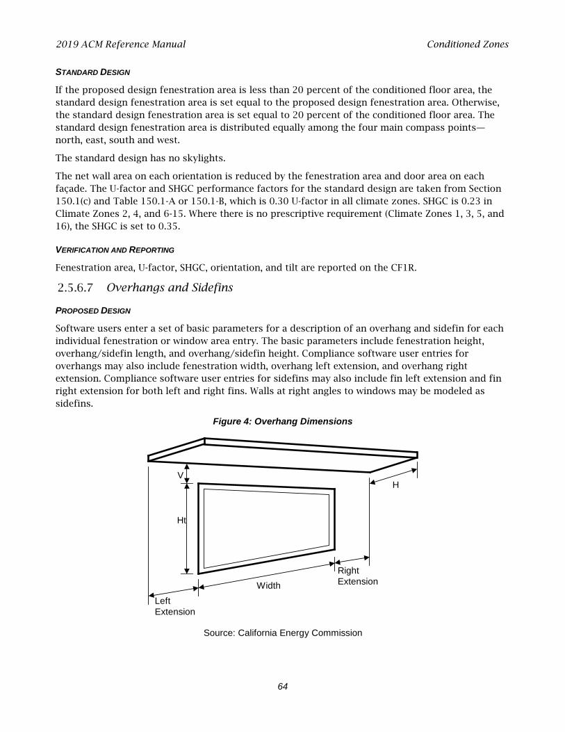
2019 ACM Reference Manual Conditioned Zones
64
STANDARD DESIGN
If the proposed design fenestration area is less than 20 percent of the conditioned floor area, the standard design fenestration area is set equal to the proposed design fenestration area. Otherwise, the standard design fenestration area is set equal to 20 percent of the conditioned floor area. The standard design fenestration area is distributed equally among the four main compass points—north, east, south and west.
The standard design has no skylights.
The net wall area on each orientation is reduced by the fenestration area and door area on each façade. The U-factor and SHGC performance factors for the standard design are taken from Section 150.1(c) and Table 150.1-A or 150.1-B, which is 0.30 U-factor in all climate zones. SHGC is 0.23 in Climate Zones 2, 4, and 6-15. Where there is no prescriptive requirement (Climate Zones 1, 3, 5, and 16), the SHGC is set to 0.35.
VERIFICATION AND REPORTING
Fenestration area, U-factor, SHGC, orientation, and tilt are reported on the CF1R.
Overhangs and Sidefins
PROPOSED DESIGN
Software users enter a set of basic parameters for a description of an overhang and sidefin for each individual fenestration or window area entry. The basic parameters include fenestration height, overhang/sidefin length, and overhang/sidefin height. Compliance software user entries for overhangs may also include fenestration width, overhang left extension, and overhang right extension. Compliance software user entries for sidefins may also include fin left extension and fin right extension for both left and right fins. Walls at right angles to windows may be modeled as sidefins.
Figure 4: Overhang Dimensions
Source: California Energy Commission
V
Ht
H
LeftExtension
RightExtensionWidth
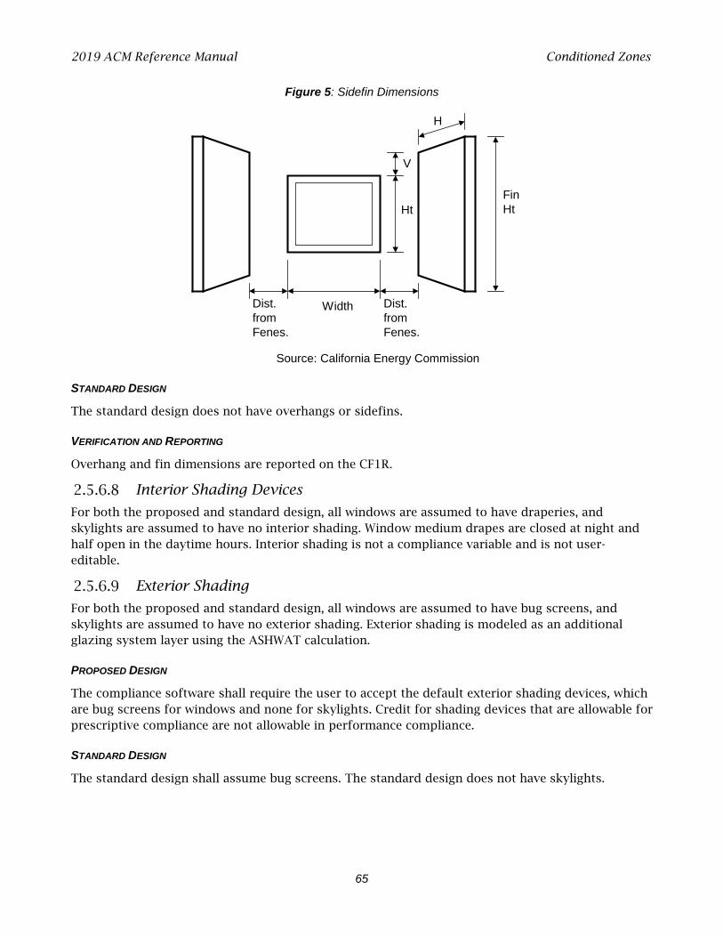
2019 ACM Reference Manual Conditioned Zones
65
Figure 5: Sidefin Dimensions
Source: California Energy Commission
STANDARD DESIGN
The standard design does not have overhangs or sidefins.
VERIFICATION AND REPORTING
Overhang and fin dimensions are reported on the CF1R.
Interior Shading Devices
For both the proposed and standard design, all windows are assumed to have draperies, and skylights are assumed to have no interior shading. Window medium drapes are closed at night and half open in the daytime hours. Interior shading is not a compliance variable and is not user-editable.
Exterior Shading
For both the proposed and standard design, all windows are assumed to have bug screens, and skylights are assumed to have no exterior shading. Exterior shading is modeled as an additional glazing system layer using the ASHWAT calculation.
PROPOSED DESIGN
The compliance software shall require the user to accept the default exterior shading devices, which are bug screens for windows and none for skylights. Credit for shading devices that are allowable for prescriptive compliance are not allowable in performance compliance.
STANDARD DESIGN
The standard design shall assume bug screens. The standard design does not have skylights.
V
Ht
H
FinHt
Width Dist.fromFenes.
Dist.fromFenes.
2019 ACM Reference Manual Conditioned Zones
66
Slab on Grade Floors
PROPOSED DESIGN
The software allows users to enter areas and exterior perimeter of slabs that are heated or unheated, covered or exposed, and with or without slab-edge insulation. Perimeter is the length of wall between conditioned space and the exterior, but it does not include edges that cannot be insulated, such as between the house and the garage. The default condition for the proposed design is that 80 percent of each slab area is carpeted or covered by walls and cabinets, and 20 percent is exposed. Inputs other than the default condition require that carpet and exposed slab conditions are documented on the construction plans.
When the proposed heating distribution is radiant floor heating (heated slab), the software user will identify that the slab is heated and model the proposed slab edge insulation. The mandatory minimum requirement is R-5 insulation in Climate Zones 1-15 and R-10 in Climate Zone 16 (Section 110.8[g], Table 110.8-A).
STANDARD DESIGN
The standard design perimeter lengths and slab on grade areas are the same as the proposed design. Eighty percent of standard design slab area is carpeted, and 20 percent is exposed. For the standard design, an unheated slab edge has no insulation with the exception of Climate Zone 16, which assumes R-7 to a depth of 16 inches. The standard design for a heated slab is a heated slab with the mandatory slab edge insulation of R-5 in Climate Zones 1-15 and R-10 in Climate Zone 16.
VERIFICATION AND REPORTING
Slab areas, perimeter lengths, and inputs of other than the default condition are reported on the CF1R.
Underground Floors
PROPOSED DESIGN
The software allows users to enter areas and depth below grade of slab floors occurring below grade. Unlike slab-on-grade floors, there is no perimeter length associated with underground floors.
STANDARD DESIGN
The standard design underground floor areas are the same as the proposed design.
Raised Floors
PROPOSED DESIGN
The software allows the user to input floor areas and constructions for raised floors over a crawl space, over exterior (garage or unconditioned), over a controlled ventilation crawl space, and concrete raised floors. The proposed floor area and constructions are consistent with the actual building design.
STANDARD DESIGN
The standard design has the same area and type of construction as the proposed design. The thermal characteristics meet Section 150.1(c) and Table 150.1-A or 150.1-B. For floor areas that are
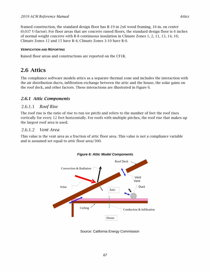
2019 ACM Reference Manual Attics
67
framed construction, the standard design floor has R-19 in 2x6 wood framing, 16-in. on center (0.037 U-factor). For floor areas that are concrete raised floors, the standard design floor is 6 inches of normal weight concrete with R-8 continuous insulation in Climate Zones 1, 2, 11, 13, 14, 16; Climate Zones 12 and 15 have R-4; Climate Zones 3-10 have R-0.
VERIFICATION AND REPORTING
Raised floor areas and constructions are reported on the CF1R.
2.6 Attics
The compliance software models attics as a separate thermal zone and includes the interaction with the air distribution ducts, infiltration exchange between the attic and the house, the solar gains on the roof deck, and other factors. These interactions are illustrated in Figure 6.
2.6.1 Attic Components
Roof Rise
The roof rise is the ratio of rise to run (or pitch) and refers to the number of feet the roof rises vertically for every 12 feet horizontally. For roofs with multiple pitches, the roof rise that makes up the largest roof area is used.
Vent Area
This value is the vent area as a fraction of attic floor area. This value is not a compliance variable and is assumed set equal to attic floor area/300.
Figure 6: Attic Model Components
Source: California Energy Commission
Duct
Vent Vent
Conduction & Infiltration
Solar
Convection & Radiation
Roof Deck
Attic
House
Ceiling
2019 ACM Reference Manual Attics
68
Fraction High
The fraction of the vent area that is high due to the presence of ridge, roof, or gable end-mounted vents. Soffit vents are considered low ventilation. The default value is zero for attics with standard ventilation. Attics with radiant barriers are required to have a vent high fraction of at least 0.3.
Roof Deck/Surface Construction
Typical roof construction types are concrete or clay tile, metal tile, or wood shakes, or other steep- or low-sloped roofing types.
Solar Reflectance
This input is a fraction that specifies the certified aged reflectance of the roofing material or 0.1 default value for uncertified materials. The installed value must be equal to or higher than the value
specified here. Roof construction with a roof membrane mass of at least 25 lbs/ft2 or a roof area
that has integrated solar collectors is assumed to meet the minimum solar reflectance.
Thermal Emittance
Thermal emittance is the certified aged thermal emittance (or emissivity) of the roofing material, or a default value. Unless a default value is modeled, the installed value must be equal to or greater than the value modeled. The default value is 0.85 if certified aged thermal emittance value is not available from the Cool Roof Rating Council (www.coolroofs.org). Roof construction with a roof
membrane mass of at least 25 lbs/ft2 or roof area incorporated integrated solar collectors is assumed to meet the minimal thermal emittance.
PROPOSED DESIGN
The conditioning is either ventilated or unventilated. Each characteristic of the roof is modeled to reflect the proposed construction. Values for solar reflectance and thermal emittance shall be default or from the Cool Roof Rating Council.
Roofs with solar collectors or with thermal mass over the roof membrane with a weight of at least 25 lbs/ft² may model the prescriptive values for solar reflectance and thermal emittance.
STANDARD DESIGN
The standard design depends on the variables of the climate zone and roof slope. Low-sloped roofs (with a roof rise of 2 feet in 12 or less) in Climate Zones 13 and 15 will have a standard design aged solar reflectance of 0.63 and a thermal emittance of 0.85.
Steep-sloped roofs in Climate Zones 10-15 will have a standard design roof with an aged solar reflectance of 0.20 and a minimum thermal emittance of 0.85.
Roofs with solar collectors or with thermal mass over the roof membrane with a weight of at least 25 lbs/ft² are assumed to meet the standard design values for solar reflectance and thermal emittance.
VERIFICATION AND REPORTING
A reflectance of 0.20 or higher is reported as a cool roof. A value higher than the default but less than 0.20 is reported as a non-standard roof reflectance value.
2019 ACM Reference Manual Attics
69
2.6.2 Ceiling Below Attic
PROPOSED DESIGN
For each conditioned zone, the user enters the area and construction of each ceiling surface that is below an attic space. The compliance software shall allow a user to enter multiple ceiling constructions. Surfaces that tilt 60 degrees or more are treated as knee walls and are not included as ceilings. The sum of areas shall equal the overall ceiling area with conditioned space on the inside and unconditioned attic space on the other side.
The compliance software creates an attic zone with a floor area equal to the sum of the areas of all the user input ceilings below an attic in the building. The user specifies the framing and spacing, the materials of the frame path, and the R-value of the insulation path for each ceiling construction.
The user inputs the proposed insulation R-value rounded to the nearest whole R-value. For simulation, all ceiling below attic insulation is assumed to have nominal properties of R-2.6 per inch, a density of 0.5 lb/ft3, and a specific heat of 0.2 Btu/lb.
STANDARD DESIGN
The standard design shall have the same area of ceiling below attic as the proposed design. The ceiling/framing construction is based on the prescriptive requirement and standard framing is assumed to be 2x4 wood trusses at 24 inches on center.
VERIFICATION AND REPORTING
The area, insulation R-value, and layer of each construction are reported on the CF1R.
2.6.3 Attic Roof Surface and Pitch
PROPOSED DESIGN
The roof pitch is the ratio of rise to run, (for example, 4:12 or 5:12). If the proposed design has more than one roof pitch, the pitch of the largest area is used.
The compliance software creates an attic zone roof. The roof area is calculated as the ceiling below attic area divided by the cosine of the roof slope where the roof slope is an angle in degrees from the horizontal. The roof area is then divided into four equal sections with each section sloping in one of the cardinal directions (north, east, south and west). Gable walls, dormers, or other exterior vertical surfaces that enclose the attic are ignored.
If the user specifies a roof with a pitch less than 2:12, the compliance software creates an attic with a flat roof that is 30 inches above the ceiling.
STANDARD DESIGN
The standard design shall have the same roof pitch, roof surface area, and orientations as the proposed design.
VERIFICATION AND REPORTING
The roof pitch is reported on the CF1R.
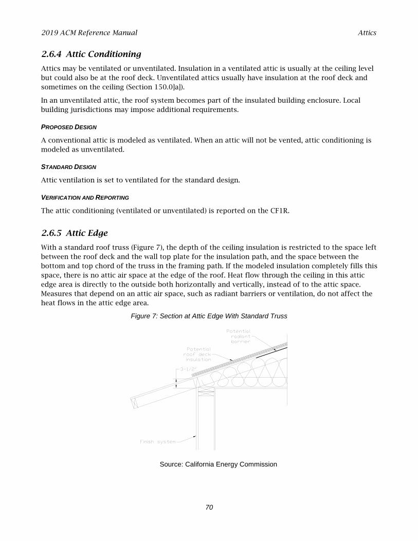
2019 ACM Reference Manual Attics
70
2.6.4 Attic Conditioning
Attics may be ventilated or unventilated. Insulation in a ventilated attic is usually at the ceiling level but could also be at the roof deck. Unventilated attics usually have insulation at the roof deck and sometimes on the ceiling (Section 150.0]a]).
In an unventilated attic, the roof system becomes part of the insulated building enclosure. Local building jurisdictions may impose additional requirements.
PROPOSED DESIGN
A conventional attic is modeled as ventilated. When an attic will not be vented, attic conditioning is modeled as unventilated.
STANDARD DESIGN
Attic ventilation is set to ventilated for the standard design.
VERIFICATION AND REPORTING
The attic conditioning (ventilated or unventilated) is reported on the CF1R.
2.6.5 Attic Edge
With a standard roof truss (Figure 7), the depth of the ceiling insulation is restricted to the space left between the roof deck and the wall top plate for the insulation path, and the space between the bottom and top chord of the truss in the framing path. If the modeled insulation completely fills this space, there is no attic air space at the edge of the roof. Heat flow through the ceiling in this attic edge area is directly to the outside both horizontally and vertically, instead of to the attic space. Measures that depend on an attic air space, such as radiant barriers or ventilation, do not affect the heat flows in the attic edge area.
Figure 7: Section at Attic Edge With Standard Truss
Source: California Energy Commission

2019 ACM Reference Manual Attics
71
A raised heel truss (Figure 8) provides additional height at the attic edge that, depending on the height Y and the ceiling insulation R, can either reduce or eliminate the attic edge area and its thermal impact.
Figure 8: Section at Attic Edge With a Raised Heel Truss
Source: California Energy Commission
For cases where the depth of insulation (including below-deck insulation depth) is greater than the available height at the attic edge, the compliance software automatically creates cathedral ceiling surfaces to represent the attic edge area and adjusts the dimensions of the attic air space using the algorithms contained in the document 2019 Residential Alternative Calculation Method Algorithms. If above-deck insulation is modeled, it is included in the attic edge cathedral ceiling constructions, but radiant barriers below the roof deck are not.
PROPOSED DESIGN
The compliance software shall allow the user to specify that a raised heel truss will be used (as supported by construction drawings), with the default being a standard truss as shown in Figure 7. If the user selects a raised heel truss, the compliance software will require the user to specify the vertical distance between the wall top plate and the bottom of the roof deck (Y in Figure 8).
STANDARD DESIGN
The standard design shall have a standard truss with the default vertical distance of 3.5 inches between wall top plate and roof deck.
VERIFICATION AND REPORTING
A raised heel truss is a special feature, and the vertical height above the top plate will be included on the CF1R.
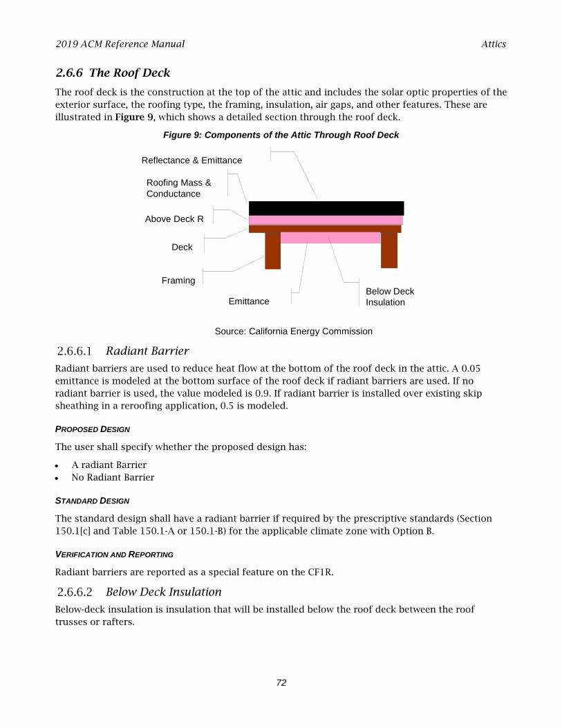
2019 ACM Reference Manual Attics
72
2.6.6 The Roof Deck
The roof deck is the construction at the top of the attic and includes the solar optic properties of the exterior surface, the roofing type, the framing, insulation, air gaps, and other features. These are illustrated in Figure 9, which shows a detailed section through the roof deck.
Figure 9: Components of the Attic Through Roof Deck
Source: California Energy Commission
Radiant Barrier
Radiant barriers are used to reduce heat flow at the bottom of the roof deck in the attic. A 0.05 emittance is modeled at the bottom surface of the roof deck if radiant barriers are used. If no radiant barrier is used, the value modeled is 0.9. If radiant barrier is installed over existing skip sheathing in a reroofing application, 0.5 is modeled.
PROPOSED DESIGN
The user shall specify whether the proposed design has:
• A radiant Barrier • No Radiant Barrier
STANDARD DESIGN
The standard design shall have a radiant barrier if required by the prescriptive standards (Section 150.1[c] and Table 150.1-A or 150.1-B) for the applicable climate zone with Option B.
VERIFICATION AND REPORTING
Radiant barriers are reported as a special feature on the CF1R.
Below Deck Insulation
Below-deck insulation is insulation that will be installed below the roof deck between the roof trusses or rafters.
Roofing Mass & Conductance
Reflectance & Emittance
Above Deck R
Deck
Framing
Emittance Below Deck Insulation

2019 ACM Reference Manual Attics
73
PROPOSED DESIGN
The compliance software shall allow the user to specify the R-value of insulation that will be installed below the roof deck between the roof trusses or rafters. The default is an uninsulated roof deck.
STANDARD DESIGN
The standard design has below-deck insulation as specified in Section 2.5.6.1.
VERIFICATION AND REPORTING
The R-value of any below-deck insulation is reported as a special feature on the CF1R.
Roof Deck and Framing
The roof deck is the structural surface that supports the roofing. The compliance software assumes a standard wood deck, and this is not a compliance variable. The size, spacing, and material of the roof deck framing are compliance variables.
PROPOSED DESIGN
The roof deck is wood siding/sheathing/decking. The compliance software shall default the roof deck framing to 2x4 trusses at 24 in. on center. The compliance software shall allow the user to specify alternative framing size, material, and framing spacing.
STANDARD DESIGN
The standard design is 2x4 trusses at 24 in. on center.
VERIFICATION AND REPORTING
Nonstandard roof deck framing or spacing is reported as a special feature on the CF1R.
Above Deck Insulation
Above-deck insulation represents the insulation value of the air gap in “concrete or clay tile” or “metal tile or wood shakes.” The R-value of any user modeled insulation layers between the roof-deck and the roofing is added to the air gap value.
PROPOSED DESIGN
This input defaults to R-0.85 for “concrete or clay tile” or for “metal tile or wood shakes” to represent the benefit of the air gap but no additional insulation. The compliance software shall allow the user to specify the R-value of additional above-deck insulation in any roof-deck construction assembly.
STANDARD DESIGN
The standard design accounts for the air gap based on roofing type but has no additional above-deck insulation.
VERIFICATION AND REPORTING
Above-deck insulation R-value is reported as a special feature on the CF1R.
2019 ACM Reference Manual Attics
74
Roofing Type and Mass
PROPOSED DESIGN
The choice of roofing type determines the air gap characteristics between the roofing material and the deck and establishes whether other inputs are needed, as described below. The choices for roof type are shown below.
• Concrete or clay tile. Both types have significant thermal mass and an air gap between the deck and the tiles.
• Metal tile or wood shakes. These are lightweight but have an air gap between the tiles or shakes and the deck. Note that tapered cedar shingles do not qualify and are treated as a conventional roof surface.
• Other steep-slope roofing types. These include asphalt and composite shingles and tapered cedar shingles. These products have no air gap between the shingles and the structural roof deck.
• Low-slope membranes. These are basically flat roofs with a slope of 2:12 or less. • Above-deck mass. The above-deck mass depends on the roofing type. The mass is 10 lbs/ft²
for concrete and clay tile and 5 lbs/ft² for metal tile, wood shakes, or other steep-slope roofing types. For low-slope roofs, the additional thermal mass is assumed to be gravel or stone, and the user chooses one of the following inputs that is less than or equal to the weight of the material being installed above the roof deck:
• No mass • 5 lbs/ft² • 10 lbs/ft² • 15 lbs/ft² • 25 lbs/ft²
STANDARD DESIGN
The roof slope shall match the proposed design. The roof type for a steep slope roof is 10 lbs/ft2 tile. The roof type for low-slope roof is lightweight roof.
VERIFICATION AND REPORTING
The roof type is reported on the CF1R.
Solar Reflectance and Thermal Emittance
PROPOSED DESIGN
The compliance software shall allow the user to default the solar reflectance and thermal emittance of the roofing. The solar reflectance product default is 0.10 for all roof types. The thermal emittance default is 0.85.
The compliance software shall allow the user to input aged solar reflectance and thermal emittance of roofing material that are rated by the Cool Roof Rating Council. The installed value must be equal to or higher than the value specified here. Roof construction with a roof membrane mass of at least 25 lbs/ft2 or roof area incorporated integrated solar collectors are assumed to meet the minimal solar reflectance.
2019 ACM Reference Manual
75
STANDARD DESIGN
The solar reflectance and thermal emittance of the standard design roofing are as specified in the prescriptive standards.
VERIFICATION AND REPORTING
Thermal emittance and solar reflectance shall be reported on the CF1R. A reflectance of 0.20 or higher is reported as a cool roof. A value higher than the default but less than 0.20 is reported as a nonstandard roof reflectance value.
2.7 Crawl Spaces
The crawl space type is either a (1) normal vented crawl space (has a conditioned space above with raised floor insulation), (2) insulated with reduced ventilation (as used in the California Building Code), or (3) sealed and mechanically ventilated crawl space (also called a controlled ventilation crawl space or CVC).
PROPOSED DESIGN
The software user will model the crawl space as a separate unconditioned zone, selecting the appropriate crawl space type, with the perimeter of the crawl space (in linear feet) and the height of the crawl space.
STANDARD DESIGN
The standard design has a typical vented crawl space when a crawl space is shown. Otherwise, the raised floor is assumed to be over exterior or unconditioned space.
VERIFICATION AND REPORTING
The crawl space zone type and characteristics shall be reported on the CF1R. A controlled ventilation crawl space shall be reported as a special feature on the CF1R.
2.8 Garage/Storage
An attached unconditioned space is modeled as a separate unconditioned zone. While the features of this space have no effect on compliance directly, it is modeled to accurately represent the building. The modeling of the garage will shade the walls adjacent to conditioned space and will have a lower air temperature (than the outside) adjacent to those walls. The walls and door that separate the conditioned zone from the garage are modeled as part of the conditioned zone.
PROPOSED DESIGN
The software user will model the area and type for the floor, exterior walls (ignore windows), large metal roll-up or wood doors (assume a 1.0 U-factor), and roof/ceiling (typically an attic or the same as the conditioned zone).
STANDARD DESIGN
The standard design building has the same features as the proposed design.
2019 ACM Reference Manual Domestic Hot Water (DHW)
76
VERIFICATION AND REPORTING
The presence of an attached garage or unconditioned space is reported as general information on the CF1R. The general characteristics of the unconditioned zone are reported on the CF1R.
2.9 Domestic Hot Water (DHW)
Water heating energy use is based on the number of dwelling units, number of bedrooms, fuel type, distribution system, water heater type, and conditioned floor area. Detailed calculation information is included in Appendix B.
PROPOSED DESIGN
The water heating system is defined by the heater type (gas, electric resistance, or heat pump), tank type, dwelling-unit distribution type, central system distribution, efficiency (either UEF or recovery efficiency with the standby loss), tank volume, exterior insulation R-value (only for indirect), rated input, and tank location (for electric resistance and heat pump water heater only).
Heat pump water heaters are defined by energy factor, volume, and tank location or, for Northwest Energy Efficiency Alliance (NEEA) rated heat pumps, by selecting the specific heater brand, model, and tank location.
Water heater and tank types include:
• Consumer storage: ≤ 75,000 Btu/h gas/propane, ≤ 12 kW electric, or ≤ 24 amps heat pump, rated with UEF.
• Consumer instantaneous: ≤ 200,000 Btu/h gas or propane, or ≤ 12 kW electric. An instantaneous water heater is a water heater with an input rating of ≥ 4,000 Btu/h/gallon of stored water, rated with a UEF.
• Residential-duty commercial storage: > 75,000 Btu/h, ≤ 105,000 Btu/h gas/propane, ≤ 12 kW electric, ≤ 24 amps heat pump, and rated storage volume < 120 gallons, rated with a UEF.
• Residential-duty commercial instantaneous: ≤ 200,000 Btu/h gas/propane, ≤ 58.6 kW electric, and rated storage volume ≤ 2 gallons, rated with a UEF.
• Commercial storage: > 75,000 Btu/h gas/propane, >105,000 Btu/h oil, or > 12 kW electric, rated with thermal efficiency and standby loss.
• Commercial instantaneous: >200,000 Btu/h gas/propane, > 12 kW electric. Instantaneous water heater is a water heater with an input rating of ≥ 4,000 Btu/h per gallon of stored water, rated with thermal efficiency.
• Heat pump water heater: ≤ 24 amps Northwest Energy Efficiency Alliance (NEEA) rating or rated with UEF.
• Mini-tank (modeled only in conjunction with an instantaneous gas water heater): a small electric storage buffering tank that may be installed downstream of an instantaneous gas water heater to mitigate delivered water temperatures (e.g., cold water sandwich effect). If the standby loss of this aftermarket tank is not listed in the Energy Commission appliance database, a standby loss of 35 W must be assumed.
2019 ACM Reference Manual Domestic Hot Water (DHW)
77
• Indirect: a tank with no heating element or combustion device used in combination with a boiler or other device serving as the heating element.
• Boiler: a water boiler that supplies hot water, rated with thermal efficiency or AFUE.
Heater element type includes:
• Electric resistance.
• Gas.
• Heat pump.
For water-heating systems serving a single dwelling unit, a dwelling unit distribution type must be specified. Dwelling unit distribution system types for systems serving individual dwelling units include:
• Standard (all distribution pipes insulated).
• Point of use.
• Central parallel piping.
• Recirculation with nondemand control (continuous pumping).
• Recirculation with demand control, push button.
• Recirculation with demand control, occupancy/motion sensor.
• HERS-required pipe insulation, all lines.
• HERS-required central parallel piping.
• HERS-required recirculation, demand control, push button.
• HERS-required recirculation with demand control, occupancy/motion sensor.
When a multifamily building has central water heating, both a dwelling unit and a central system distribution type must be specified. Dwelling unit distribution types for this case include:
• Standard (all distribution pipes insulated).
• HERS-required pipe insulation, all lines.
Multifamily central hot water heating central system distribution types include:
• No loops or recirculation system pump.
• Recirculation with no control (continuous pumping).
• Recirculation demand control (standard design for new construction).
• Recirculation with temperature modulation control.
• Recirculation with temperature modulation and monitoring.
Some distribution systems have an option to increase the amount of credit received if the option for HERS verification is selected. See Appendix B for the amount of credit and Reference Appendices, Residential Appendix Table RA2-1 for a summary of inspection requirements.

2019 ACM Reference Manual Domestic Hot Water (DHW)
78
Distribution Compactness
Applicable to single dwelling units or multifamily with individual water heater in each dwelling unit. Distribution compactness identifies the proximity between the water heater and use points. The distribution compactness of the water heating system must be specified. The choices include:
• None.
• Compact distribution basic credit.
• Compact distribution expanded credit (HERS).
For both compact distribution basic credit and expanded credit, the plan view distance from the water heater to the master bedroom, the kitchen, and the furthest fixture must be specified. The software will determine if the distances qualify for the credit.
Drain Water Heat Recovery
Drain water heat recovery (DWHR) is a system where the waste heat from shower drains is used to preheat the cold inlet water. The preheat water can be routed to the served shower, water heater, or both.
The user specifies the DHWR device for the water heating system. The rated efficiency of the DWHR device, the number of shower(s) served, and the configuration must be specified. The configuration choices include:
• Equal flow to shower and water heater: The potable-side heat exchanger output feeds both the fixture and the water heater inlet. Potable and drain flow rates are equal, assuming no other simultaneous hot water draws.
• Unequal flow to shower: The potable-side heat exchanger output feeds the inlet(s) of the water heater(s) that are part of the parent DHW system. (The inlet temperature is adjusted to reflect recovered heat.)
• Unequal flow to water heater: The potable-side heat exchanger output feeds only the associated fixture.
Multiple DHWR devices can be used for a water heater system.
Drain water heat recovery is a HERS-verified measure.
STANDARD DESIGN
2.9.2 Individual Dwelling Units
If the proposed water heater is natural gas or propane, the standard design is a single gas or propane consumer instantaneous water heater for each dwelling unit. The single consumer instantaneous water heater is modeled with an input of 200,000 Btu/h, a tank volume of zero gallons, a high draw pattern, and a UEF meeting the minimum federal standards. The current minimum federal standard for a high-draw-pattern instantaneous water heater is 0.81 UEF or the equivalent of 0.82 energy factor for the standard system.
If the proposed water heater is an electric resistance or a heat pump water heater, the standard design is a single heat pump water heater with a 2.0 UEF. The water heater is installed in an attached garage (if available) or the location specified in Table 24, with compact distribution credit
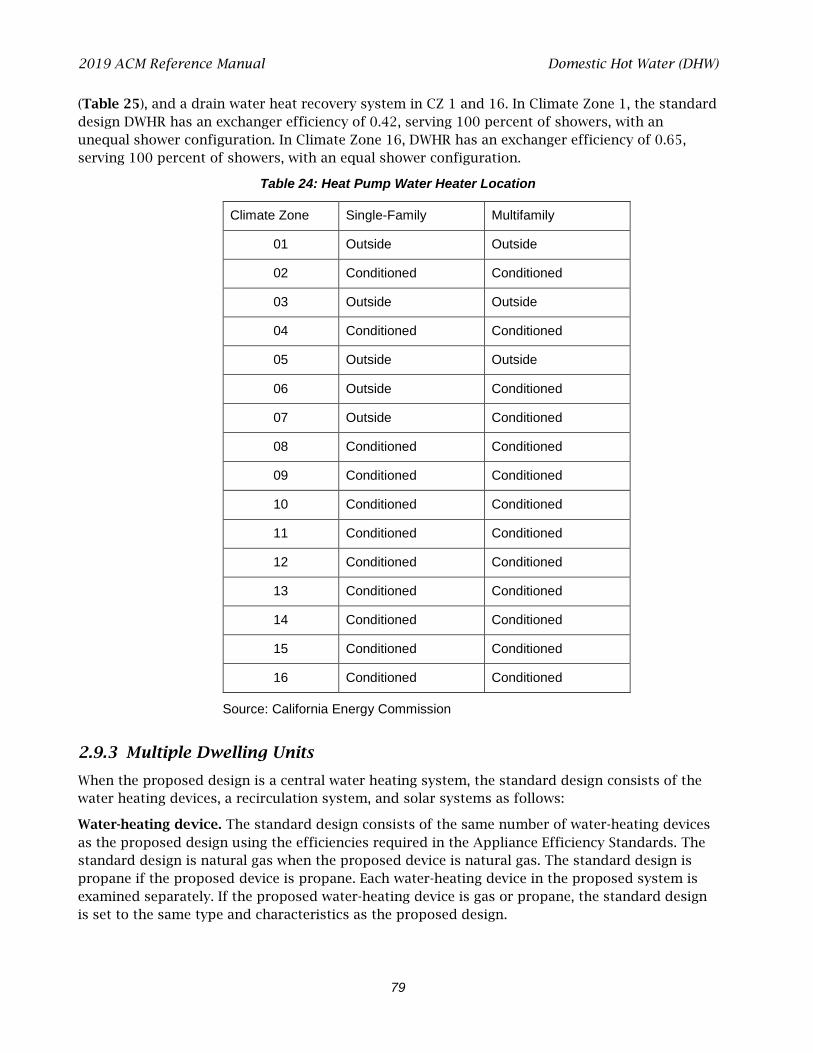
2019 ACM Reference Manual Domestic Hot Water (DHW)
79
(Table 25), and a drain water heat recovery system in CZ 1 and 16. In Climate Zone 1, the standard design DWHR has an exchanger efficiency of 0.42, serving 100 percent of showers, with an unequal shower configuration. In Climate Zone 16, DWHR has an exchanger efficiency of 0.65, serving 100 percent of showers, with an equal shower configuration.
Table 24: Heat Pump Water Heater Location
Climate Zone Single-Family Multifamily
01 Outside Outside
02 Conditioned Conditioned
03 Outside Outside
04 Conditioned Conditioned
05 Outside Outside
06 Outside Conditioned
07 Outside Conditioned
08 Conditioned Conditioned
09 Conditioned Conditioned
10 Conditioned Conditioned
11 Conditioned Conditioned
12 Conditioned Conditioned
13 Conditioned Conditioned
14 Conditioned Conditioned
15 Conditioned Conditioned
16 Conditioned Conditioned
Source: California Energy Commission
2.9.3 Multiple Dwelling Units
When the proposed design is a central water heating system, the standard design consists of the water heating devices, a recirculation system, and solar systems as follows:
Water-heating device. The standard design consists of the same number of water-heating devices as the proposed design using the efficiencies required in the Appliance Efficiency Standards. The standard design is natural gas when the proposed device is natural gas. The standard design is propane if the proposed device is propane. Each water-heating device in the proposed system is examined separately. If the proposed water-heating device is gas or propane, the standard design is set to the same type and characteristics as the proposed design.

2019 ACM Reference Manual Domestic Hot Water (DHW)
80
If the proposed water-heating device is electric resistance or heat pump with no recirculating loops (fewer than eight dwelling units), then the standard design is a heat pump water heater with 2.0 UEF. If the proposed central water-heating device is electric resistance or heat pump with recirculating loops, the standard design is natural gas or propane.
The appropriate efficiencies and standby losses for each standard water-heating device are then assigned to match the minimum federal requirements. The standards for consumer water heaters, as defined by 42 U.S.C 6291(16), are specified in 10 CFR 430.32(d); the standards for commercial water heaters, as defined by 42 U.S.C 6291(16), are specified in 10 CFR 431.110.
Table 25: Electric Water Heating Compactness Factor
Climate Zone Compactness Factor
01 Enhanced (0.6)
02 Enhanced (0.6)
03 Enhanced (0.6)
04 Enhanced (0.6)
05 Enhanced (0.6)
06 Basic (0.7)
07 Basic (0.7)
08 Basic (0.7)
09 Enhanced (0.6)
10 Enhanced (0.6)
11 Enhanced (0.6)
12 Enhanced (0.6)
13 Enhanced (0.6)
14 Enhanced (0.6)
15 Basic (0.7)
16 Enhanced (0.6)
Source: California Energy Commission
Recirculating system. The standard design includes a recirculation system with controls that regulate pump operation based on measurement of hot water demand and hot water return temperature, and capable of turning off the system as described in Appendix B4 Hourly Recirculation Distribution Loss for Central Water Heating Systems. The standard design has one recirculation loop.
Solar thermal water-heating system. The standard design has a solar water heating system meeting the installation criteria specified in Reference Residential Appendix RA4 and with a minimum solar savings fraction of 0.20 in Climate Zones 1-9, or 0.35 in Climate Zones 10-16.
2019 ACM Reference Manual Additions/Alterations
81
VERIFICATION AND REPORTING
All modeled features and the number of devices modeled for the water heating system are reported on the CF1R. Electric resistance and heat pump water heaters indicate the location of the water heater. NEEA-rated heat pumps are identified by the brand and model, which must be verified by the building inspector.
Where water heating system features or distribution systems specify or require HERS verification, those features are listed in the HERS required verification listings on the CF1R.
2.9.4 Solar Thermal Water Heating Credit
When a water heating system has a solar thermal system to provide part of the water heating, the solar fraction (SF) is determined using the Energy Commission Solar Water Heating Calculator, OG-100 calculation method, or the certified OG-300 rating. (Note: The OG-300 rating can be used only for system servings individual dwelling units and not central systems.) The calculation method requires that the user specify the climate zone and conditioned floor area, in addition to published data for the solar thermal water heating system.
2.10 Additions/Alterations
Addition and alteration compliance is based on standards Section 150.2. The energy budget for additions and alterations is based on TDV energy. Alterations must model the entire dwelling unit. Additions may be modeled as addition alone, as “existing+addition+alteration,” or the entire building may be modeled as an entirely new building (whole building, Section 150.2[c]).
Additions that are 1,000 ft2 or less are exempt from dwelling unit ventilation requirements of Section 150.0(o)1C, 150.0(o)1E, or 150.0(o)1F. When an addition to any building creates a new dwelling unit, this exception does not apply.
The standard design does not include:
• Cool roof when an addition is 300 ft2 or less. • Ventilation cooling for additions that are 1,000 ft2 or less. • Solar generation/PV requirements.
2.10.1 Whole Building
The entire proposed building, including all additions or alterations or both, is modeled the same as a newly constructed building. The building complies if the proposed design uses equal or less energy than the standard design.
2.10.2 Alteration-Alone Approach
The proposed alteration alone floor area is modeled. The alteration requirements of Section 150.2(b) are applied to any features that do not exist.
2019 ACM Reference Manual Additions/Alterations
82
2.10.3 Addition-Alone Approach
The proposed addition alone is modeled the same as a newly constructed building except that the internal gains are prorated based on the size of the dwelling. None of the exceptions included for prescriptive additions, which are implemented in the existing plus addition compliance approach (Section 2.10.4), are given to the addition alone approach. (See Standards Section 150.2[a]2.B.) The addition complies if the proposed design uses equal or less space heating, space cooling, and water heating TDV energy than the standard design.
The addition-alone approach shall not be used when alterations to the existing building are proposed. Modifications to any surfaces between the existing building and the addition are part of the addition and are not considered alterations.
PROPOSED DESIGN
The user shall indicate that an addition alone is being modeled and enter the conditioned floor area of the addition. Any surfaces that are between the existing building and the addition are not modeled or are treated as adiabatic surfaces. All other features of the addition shall be modeled the same as a newly constructed building.
When an existing HVAC system is extended to serve the addition, the proposed design shall assume the same efficiency for the HVAC equipment as the standard design. (See Sections 2.4.1 and 2.4.5.)
When a dual-glazed greenhouse or garden window is installed in an addition or alteration, the proposed design U-factor can be assumed to be 0.30.
STANDARD DESIGN
The addition alone is modeled the same as a newly constructed building, with the following exceptions:
A. When roofing requirements are included in Table 150.1-A or 150.1-B, they are included in the standard design if the added conditioned floor area is greater than 300 ft2.
B. When ventilation cooling (whole-house fan) is required by Table 150.1-A or 150.1-B, it is included in the standard design when the added conditioned floor area is greater than 1,000 ft2. The capacity shall be based on 1.5 CFM/ft2 of conditioned floor area for the entire dwelling unit conditioned floor area.
C. When compliance with indoor air quality requirements of Section 150.0(o) apply to an addition with greater than 1,000 ft2 added, the conditioned floor area of the entire dwelling unit shall be used to determine the required ventilation airflow. For additions with 1,000 ft2 or less of added conditioned floor area, no indoor air quality requirements apply.
D. PV requirements are not included.
2.10.4 Existing + Addition + Alteration Approach
Standards Section 150.2(a)2 contains the provisions for additions and Section (b)2 for alterations when the existing building is included in the calculations. These provisions are the “Existing + Addition + Alteration” (or “E+A+A”) performance approach.
2019 ACM Reference Manual Additions/Alterations
83
PROPOSED DESIGN
The proposed design is modeled by identifying each energy feature as part of the existing building (as existing, altered, or new), or as part of the addition. The compliance software uses this information to create an E+A+A standard design using the rules in the standards that take into account whether altered components meet or exceed the threshold at which they receive a compliance credit and whether any related measures are triggered by altering a given component.
For building surfaces and systems designated below, all compliance software must provide an input field with labels for the proposed design, which define how the standard design requirements are established based on the option selected by the software user:
• Existing: The surface or system remains unchanged within the proposed design. (Both standard design and proposed design have the same features and characteristics.)
• Altered: the surface or system is altered in the proposed design. No verification of existing conditions is assumed with this designation.
• Verified Altered: the surface or system is altered in the proposed design, and the original condition is verified by a HERS rater (an optional selection).
• New: a new surface or system is added in the proposed design (may be in the existing building or the addition).
Deleted features are not included in the proposed design.
Section 150.2, Table 150.2-C specifies the details of the standard design for altered components based on whether verification of existing conditions is selected or not:
Altered with no third-party verification of existing conditions (the default selection). This compliance path does not require an on-site inspection of existing conditions prior to the start of construction. The attributes of the existing condition is undefined, with the standard design for altered components based on Section 150.2, Table 150.2-B, and the climate zone. Energy compliance credit or penalty is a function of the difference between the value for that specific feature allowed in Table 150.2-B and the modeled/installed efficiency of the feature. Verified Altered existing conditions. This compliance path requires that a HERS rater perform an on-site inspection of prealteration conditions prior to construction. If an altered component or system meets or exceeds the prescriptive alteration requirements, the compliance software uses the user-defined and verified existing condition as the standard design value. Energy compliance credit is then based on the difference between the verified existing condition for that altered feature and the modeled/installed efficiency of the proposed design.
QII
STANDARD DESIGN
The standard design includes QII for additions greater than 700 square feet in any low-rise single-family building in Climate Zones 1-16 and in any low-rise multifamily building in Climate Zones 1-6 and 8-16 (Section 150.2[a]1Bv).
The provisions of Section 150.2(a)1Aiv, as applied to converting an existing unconditioned space to conditioned space, are accommodations made by the HERS rater in the field. No adjustments to the energy budget are made.
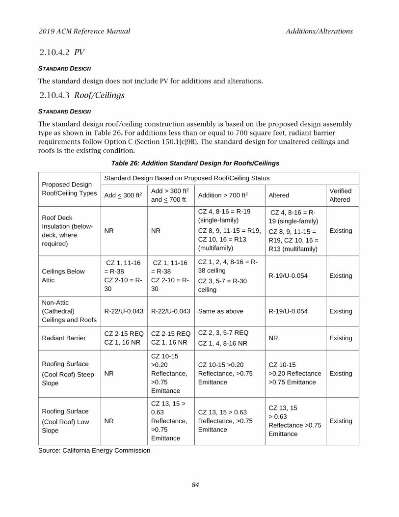
2019 ACM Reference Manual Additions/Alterations
84
PV
STANDARD DESIGN
The standard design does not include PV for additions and alterations.
Roof/Ceilings
STANDARD DESIGN
The standard design roof/ceiling construction assembly is based on the proposed design assembly type as shown in Table 26. For additions less than or equal to 700 square feet, radiant barrier requirements follow Option C (Section 150.1[c]9B). The standard design for unaltered ceilings and roofs is the existing condition.
Table 26: Addition Standard Design for Roofs/Ceilings
Proposed Design Roof/Ceiling Types
Standard Design Based on Proposed Roof/Ceiling Status
Add < 300 ft2 Add > 300 ft2
and < 700 ft Addition > 700 ft2 Altered Verified Altered
Roof Deck Insulation (below-deck, where required)
NR NR
CZ 4, 8-16 = R-19 (single-family) CZ 8, 9, 11-15 = R19, CZ 10, 16 = R13 (multifamily)
CZ 4, 8-16 = R-19 (single-family) CZ 8, 9, 11-15 = R19, CZ 10, 16 = R13 (multifamily)
Existing
Ceilings Below Attic
CZ 1, 11-16 = R-38 CZ 2-10 = R-30
CZ 1, 11-16 = R-38 CZ 2-10 = R-30
CZ 1, 2, 4, 8-16 = R-38 ceiling CZ 3, 5-7 = R-30 ceiling
R-19/U-0.054 Existing
Non-Attic (Cathedral) Ceilings and Roofs
R-22/U-0.043 R-22/U-0.043 Same as above R-19/U-0.054 Existing
Radiant Barrier CZ 2-15 REQ CZ 1, 16 NR
CZ 2-15 REQ CZ 1, 16 NR
CZ 2, 3, 5-7 REQ CZ 1, 4, 8-16 NR
NR Existing
Roofing Surface (Cool Roof) Steep Slope
NR
CZ 10-15 >0.20 Reflectance, >0.75 Emittance
CZ 10-15 >0.20 Reflectance, >0.75 Emittance
CZ 10-15 >0.20 Reflectance >0.75 Emittance
Existing
Roofing Surface (Cool Roof) Low Slope
NR
CZ 13, 15 > 0.63 Reflectance, >0.75 Emittance
CZ 13, 15 > 0.63 Reflectance, >0.75 Emittance
CZ 13, 15 > 0.63 Reflectance >0.75 Emittance
Existing
Source: California Energy Commission
2019 ACM Reference Manual Additions/Alterations
85
Exterior Walls and Doors
The software allows the user to indicate whether a new wall in an addition is an extension of an existing wood-framed wall and, if so, the dimensions of the existing wall. The standard design exterior wall construction assembly is based on a wood-framed wall with R-15 cavity insulation for existing 2x4 walls or R-21 cavity insulation for existing 2x6 walls.
The software allows the user to indicate if a wall is existing, where siding is not removed or replaced. The user also identifies if the walls have 2x4 or 2x6 framing.. The standard design exterior wall construction assembly is based on a wood-framed wall with R-15 cavity insulation for existing 2x4 walls or R-21 cavity insulation for existing 2x6 walls.
PROPOSED DESIGN
Existing structures with insulated wood-framed walls that are being converted to conditioned space using an E+A+A approach are allowed to show compliance using the existing wall framing, without having to upgrade to current prescriptive continuous insulation requirements. The walls are modeled as an assembly with the existing framing and either R-15 (in 2x4 framing) or R-21 (in 2x6 framing) insulation (exception to Section 150.0[c]1 and Section 150.2[a]1).
STANDARD DESIGN
The areas, orientation, and tilt of existing, new, and altered net exterior wall areas (with windows and doors subtracted) are the same in the existing and addition portions of standard design as in the proposed design.
If the proposed wall area is framed, the gross exterior wall area (excluding knee walls) is equally divided among the four building orientations: front, left, back and right. The gross exterior wall area of any unframed walls is also equally divided among the four orientations in the standard design.
The standard design exterior wall construction assembly is based on the proposed design assembly type as shown in Table 27. Framed walls are modeled as 16-in. on center wood framing. The standard design for unaltered walls is the existing condition.
The standard design for exterior opaque or swinging doors is 0.02 U-factor. Fire-rated doors (from the house to garage) use the proposed design door U-factor as the standard design U-factor.
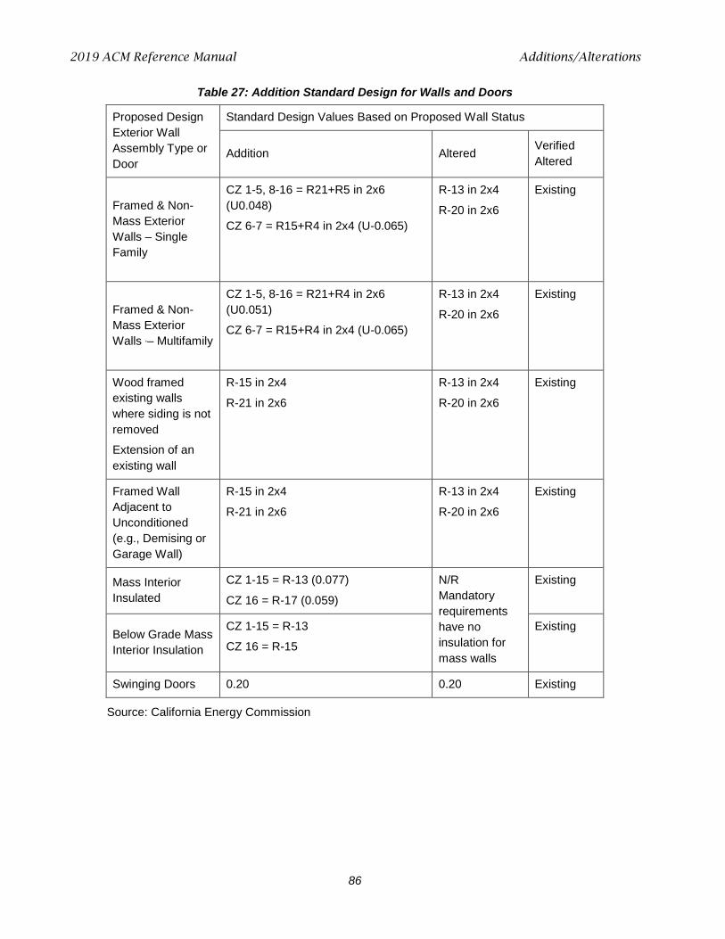
2019 ACM Reference Manual Additions/Alterations
86
Table 27: Addition Standard Design for Walls and Doors
Proposed Design Exterior Wall Assembly Type or Door
Standard Design Values Based on Proposed Wall Status
Addition Altered Verified Altered
Framed & Non-Mass Exterior Walls – Single Family
CZ 1-5, 8-16 = R21+R5 in 2x6 (U0.048)
CZ 6-7 = R15+R4 in 2x4 (U-0.065)
R-13 in 2x4
R-20 in 2x6
Existing
Framed & Non-Mass Exterior Walls ,– Multifamily
CZ 1-5, 8-16 = R21+R4 in 2x6 (U0.051)
CZ 6-7 = R15+R4 in 2x4 (U-0.065)
R-13 in 2x4
R-20 in 2x6
Existing
Wood framed existing walls where siding is not removed
Extension of an existing wall
R-15 in 2x4
R-21 in 2x6
R-13 in 2x4
R-20 in 2x6
Existing
Framed Wall Adjacent to Unconditioned (e.g., Demising or Garage Wall)
R-15 in 2x4
R-21 in 2x6
R-13 in 2x4
R-20 in 2x6
Existing
Mass Interior Insulated
CZ 1-15 = R-13 (0.077)
CZ 16 = R-17 (0.059)
N/R Mandatory requirements have no insulation for mass walls
Existing
Below Grade Mass Interior Insulation
CZ 1-15 = R-13
CZ 16 = R-15
Existing
Swinging Doors 0.20 0.20 Existing
Source: California Energy Commission
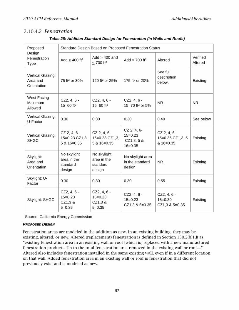
2019 ACM Reference Manual Additions/Alterations
87
Fenestration
Table 28: Addition Standard Design for Fenestration (in Walls and Roofs)
Proposed Design Fenestration Type
Standard Design Based on Proposed Fenestration Status
Add < 400 ft2 Add > 400 and < 700 ft2 Add > 700 ft2 Altered Verified
Altered
Vertical Glazing: Area and Orientation
75 ft2 or 30% 120 ft2 or 25% 175 ft2 or 20%
See full description below.
Existing
West Facing Maximum Allowed
CZ2, 4, 6 -15=60 ft2
CZ2, 4, 6 -15=60 ft2
CZ2, 4, 6 -15=70 ft2 or 5% NR NR
Vertical Glazing: U-Factor 0.30 0.30 0.30 0.40 See below
Vertical Glazing: SHGC
CZ 2, 4, 6-15=0.23 CZ1,3, 5 & 16=0.35
CZ 2, 4, 6-15=0.23 CZ1,3, 5 & 16=0.35
CZ 2, 4, 6-15=0.23 CZ1,3, 5 & 16=0.35
CZ 2, 4, 6-15=0.35 CZ1,3, 5 & 16=0.35
Existing
Skylight: Area and Orientation
No skylight area in the standard design
No skylight area in the standard design
No skylight area in the standard design
NR Existing
Skylight: U-Factor 0.30 0.30 0.30 0.55 Existing
Skylight: SHGC
CZ2, 4, 6 -15=0.23 CZ1,3 & 5=0.35
CZ2, 4, 6 -15=0.23 CZ1,3 & 5=0.35
CZ2, 4, 6 -15=0.23 CZ1,3 & 5=0.35
CZ2, 4, 6 -15=0.30 CZ1,3 & 5=0.35
Existing
Source: California Energy Commission
PROPOSED DESIGN
Fenestration areas are modeled in the addition as new. In an existing building, they may be existing, altered, or new. Altered (replacement) fenestration is defined in Section 150.2(b)1.B as “existing fenestration area in an existing wall or roof [which is] replaced with a new manufactured fenestration product... Up to the total fenestration area removed in the existing wall or roof....“ Altered also includes fenestration installed in the same existing wall, even if in a different location on that wall. Added fenestration area in an existing wall or roof is fenestration that did not previously exist and is modeled as new.

2019 ACM Reference Manual Additions/Alterations
88
STANDARD DESIGN
Standard design fenestration U-factor and SHGC are based on the proposed design fenestration as shown in Table 28. Vertical glazing includes all fenestration in exterior walls such as windows, clerestories, and glazed doors. Skylights include all glazed openings in roofs and ceilings.
New fenestration in an alteration is modeled with the same U-factor and SHGC as required for an addition.
West-facing limitations are combined with the maximum fenestration allowed and are not an additional allowance.
The standard design is set for fenestration areas and orientations as shown in Table 28:
• Proposed design < allowed % total fenestration area:
In the existing building, the standard design uses the same area and orientation of each existing or altered fenestration area (in the respective existing or altered wall or roof.)
In the addition, new fenestration is divided equally among the four project compass points similar to new gross wall areas in the addition described above.
• Proposed design > allowed % total fenestration area:
The standard design first calculates the allowed total fenestration area as the total existing and altered fenestration area in existing or altered walls and roofs. Added to this is the percent of fenestration allowed in the addition, based on the conditioned floor area of the addition.
Overhangs, Sidefins and Other Exterior Shading
STANDARD DESIGN
The standard design for a proposed building with overhangs, sidefins, and exterior shades is shown in Table 29. Exterior shading (limited to bug screens) is treated differently than fixed overhangs and sidefins, as explained in Section 2.5.6.9.
Table 29: Addition Standard Design for Overhangs, Sidefins, and Other Exterior Shading
Proposed Design Shading Type
Standard Design Based on Proposed Shading Status
Addition Altered Verified Altered
Overhangs and Sidefins No overhangs or sidefins Proposed altered condition Same as altered
Exterior Shading
Standard (bug screens on fenestration, none on skylights)
Proposed altered condition Existing exterior shading
Window Film No window film Proposed altered condition Existing exterior shading
Source: California Energy Commission

2019 ACM Reference Manual Additions/Alterations
89
Window Film
PROPOSED DESIGN
A window film must have at least a 10-year warranty and is treated as a window replacement. The values modeled are either the default values from Tables 110.6-A and 110.6-B or the NFRC Window Film Energy Performance Label.
Floors
STANDARD DESIGN
Table 150.2-C requires that the standard design be based on the mandatory requirements from Section 150.0(d). The standard design for floors is shown in Table 30.
Table 30: Addition Standard Design for Raised Floor, Slab-on-Grade, and Raised Slab
Proposed Design Floor Type
Standard Design Based on Proposed Floor Status
Addition Altered (mandatory) Verified Altered
Raised Floor Over Crawl Space or Over Exterior
R-19 in 2x6 16” o.c. wood framing
R-19 in 2x6 16” o.c. wood framing
If proposed U < 0.037, standard design = existing raised; if proposed U > 0.037, standard design = 0.037
Slab-on-Grade: Unheated
CZ1-15: R-0
CZ16: R-7 16” vertical
R-0 Existing unheated slab-on-grade
Slab-on-Grade: Heated
CZ1-15: R-5 16” vertical
CZ 16: R-10 16” vertical
CZ1-15: R-5 16” vertical
CZ 16: R-10 16” vertical
Existing heated slab-on-grade
Raised Concrete Slab
CZ1,2,11,13,14,16: R-8 CZ3-10: R-0 CZ12,15: R-4
R-0 Existing raised concrete slab
Source: California Energy Commission
Thermal Mass
STANDARD DESIGN
The standard design for thermal mass in existing plus addition plus alteration calculations is the same as for all newly constructed buildings as explained in Section 2.5.4.1.
Air Leakage and Infiltration
Standard design air leakage and infiltration is shown in Table 31.
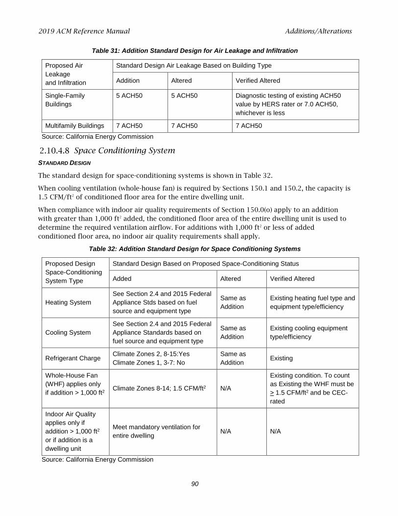
2019 ACM Reference Manual Additions/Alterations
90
Table 31: Addition Standard Design for Air Leakage and Infiltration
Proposed Air Leakage and Infiltration
Standard Design Air Leakage Based on Building Type
Addition Altered Verified Altered
Single-Family Buildings
5 ACH50 5 ACH50 Diagnostic testing of existing ACH50 value by HERS rater or 7.0 ACH50, whichever is less
Multifamily Buildings 7 ACH50 7 ACH50 7 ACH50 Source: California Energy Commission
Space Conditioning System
STANDARD DESIGN
The standard design for space-conditioning systems is shown in Table 32.
When cooling ventilation (whole-house fan) is required by Sections 150.1 and 150.2, the capacity is 1.5 CFM/ft2 of conditioned floor area for the entire dwelling unit.
When compliance with indoor air quality requirements of Section 150.0(o) apply to an addition with greater than 1,000 ft2 added, the conditioned floor area of the entire dwelling unit is used to determine the required ventilation airflow. For additions with 1,000 ft2 or less of added conditioned floor area, no indoor air quality requirements shall apply.
Table 32: Addition Standard Design for Space Conditioning Systems
Proposed Design Space-Conditioning System Type
Standard Design Based on Proposed Space-Conditioning Status
Added Altered Verified Altered
Heating System See Section 2.4 and 2015 Federal Appliance Stds based on fuel source and equipment type
Same as Addition
Existing heating fuel type and equipment type/efficiency
Cooling System See Section 2.4 and 2015 Federal Appliance Standards based on fuel source and equipment type
Same as Addition
Existing cooling equipment type/efficiency
Refrigerant Charge Climate Zones 2, 8-15:Yes Climate Zones 1, 3-7: No
Same as Addition Existing
Whole-House Fan (WHF) applies only if addition > 1,000 ft2 Climate Zones 8-14; 1.5 CFM/ft2 N/A
Existing condition. To count as Existing the WHF must be > 1.5 CFM/ft2 and be CEC-rated
Indoor Air Quality applies only if addition > 1,000 ft2 or if addition is a dwelling unit
Meet mandatory ventilation for entire dwelling N/A N/A
Source: California Energy Commission
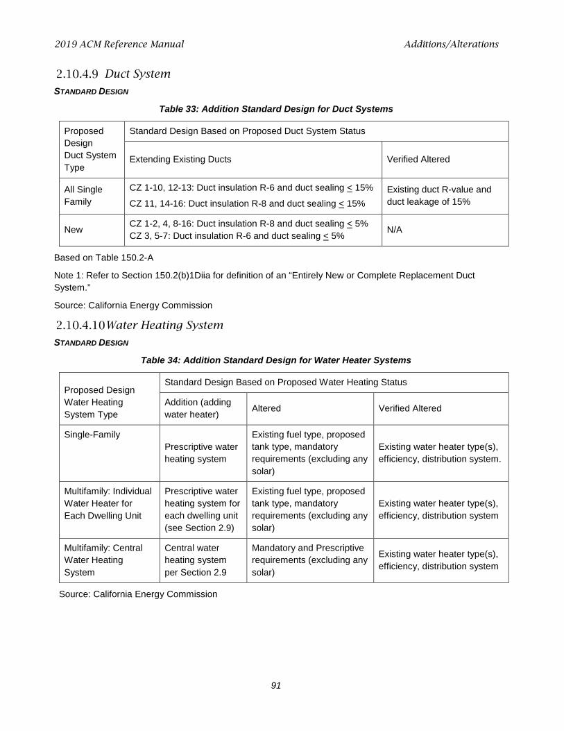
2019 ACM Reference Manual Additions/Alterations
91
Duct System
STANDARD DESIGN
Table 33: Addition Standard Design for Duct Systems
Proposed Design Duct System Type
Standard Design Based on Proposed Duct System Status
Extending Existing Ducts Verified Altered
All Single Family
CZ 1-10, 12-13: Duct insulation R-6 and duct sealing < 15%
CZ 11, 14-16: Duct insulation R-8 and duct sealing < 15% Existing duct R-value and duct leakage of 15%
New CZ 1-2, 4, 8-16: Duct insulation R-8 and duct sealing < 5% CZ 3, 5-7: Duct insulation R-6 and duct sealing < 5% N/A
Based on Table 150.2-A
Note 1: Refer to Section 150.2(b)1Diia for definition of an “Entirely New or Complete Replacement Duct System.”
Source: California Energy Commission
Water Heating System
STANDARD DESIGN
Table 34: Addition Standard Design for Water Heater Systems
Proposed Design Water Heating System Type
Standard Design Based on Proposed Water Heating Status
Addition (adding water heater) Altered Verified Altered
Single-Family Prescriptive water heating system
Existing fuel type, proposed tank type, mandatory requirements (excluding any solar)
Existing water heater type(s), efficiency, distribution system.
Multifamily: Individual Water Heater for Each Dwelling Unit
Prescriptive water heating system for each dwelling unit (see Section 2.9)
Existing fuel type, proposed tank type, mandatory requirements (excluding any solar)
Existing water heater type(s), efficiency, distribution system
Multifamily: Central Water Heating System
Central water heating system per Section 2.9
Mandatory and Prescriptive requirements (excluding any solar)
Existing water heater type(s), efficiency, distribution system
Source: California Energy Commission

2019 ACM Reference Manual Documentation
92
2.11 Documentation
The software shall be capable of displaying and printing an output of the energy use summary and a text file of the building features. These are the same features as shown on the CF1R when generated using the report manager.
See public domain software user guide or vendor software guide for detailed modeling guidelines.
2019 ACM Reference Manual EDR Adjustments
93
3 Energy Design Rating Details The energy design rating (EDR) is an alternate way to express the energy performance of a home using a scoring system where 100 represents the energy performance of a reference design building meeting the envelope requirements of the 2006 International Energy Conservation Code (IECC). The EDR is similar to the energy rating index in the 2015 IECC and the 2014 Residential Energy Services Network (RESNET) standard. Combining high levels of energy efficiency with generating renewable energy, a score of zero or less can be achieved.
Buildings complying with the current Building Energy Efficiency Standards are more efficient than the 2006 IECC, so most newly constructed buildings will have EDR scores below 100. Buildings with renewable generation like PV can achieve a negative score. If an EDR were calculated for an older inefficient home, the score would likely be well over 100.
3.1 EDR Adjustments
The software calculates an energy design ratings (EDR) as described in Section 2.1.1. The EDR implementation is limited to newly constructed single-family and multifamily dwellings.
To calculate the EDR, the user enters the proposed home with additional inputs for PV, batteries, and other flexibility measures.
The software then calculates the proposed design energy use and the standard design energy use in accordance with the normal compliance rules. Additional annual simulations are performed to determine the reference design energy use, as described in Section 2.1.4.
There are adjustments made to these EDR calculations to address the issue that the 2006 IECC includes efficiency specifications that result in significantly different levels of total energy use in the reference design for gas and electric equipment, and appliances. These adjustments are needed to ensure that homes using gas water-heating equipment and gas appliances are not penalized in the EDR results, as compared to homes using electric water-heating equipment and electric appliances. This adjustment provides EDRs for gas and electric homes that implement a fuel-neutral approach in the reference design total energy use.
Four quantities are reported for the EDR ratings. The EDR of the standard design building is provided to illustrate how the 2019 standard design compares with the reference design. The EDR score of the proposed design is provided separately from the EDR value of installed PV so that the effects of efficiency and renewable energy can both be seen. The final EDR for the proposed building includes both the effects of efficiency and PV.
The EDR values are calculated for each end use and fuel type for the standard and proposed designs. The general form of the adjustment is:
EDR = EU / EU reference x 100 Equation 13
Where:
EU = Proposed or Standard Design Energy Use (kTDV/ft2)
EU reference = Reference Design Energy Use (kTDV/ft2)
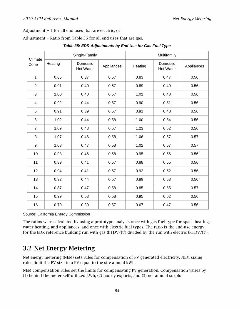
2019 ACM Reference Manual Net Energy Metering
94
Adjustment = 1 for all end uses that are electric; or
Adjustment = Ratio from Table 35 for all end uses that are gas.
Table 35: EDR Adjustments by End Use for Gas Fuel Type
Climate Zone
Single-Family Multifamily
Heating Domestic Hot Water Appliances Heating Domestic
Hot Water Appliances
1 0.85 0.37 0.57 0.83 0.47 0.56
2 0.91 0.40 0.57 0.89 0.49 0.56
3 1.00 0.40 0.57 1.01 0.48 0.56
4 0.92 0.44 0.57 0.90 0.51 0.56
5 0.91 0.39 0.57 0.91 0.48 0.56
6 1.02 0.44 0.58 1.00 0.54 0.56
7 1.09 0.43 0.57 1.23 0.52 0.56
8 1.07 0.46 0.58 1.06 0.57 0.57
9 1.03 0.47 0.58 1.02 0.57 0.57
10 0.98 0.46 0.58 0.95 0.56 0.56
11 0.89 0.41 0.57 0.88 0.55 0.56
12 0.94 0.41 0.57 0.92 0.52 0.56
13 0.92 0.44 0.57 0.89 0.53 0.56
14 0.87 0.47 0.58 0.85 0.55 0.57
15 0.99 0.53 0.58 0.95 0.62 0.56
16 0.70 0.39 0.57 0.67 0.47 0.56
Source: California Energy Commission
The ratios were calculated by using a prototype analysis once with gas fuel type for space heating, water heating, and appliances, and once with electric fuel types. The ratio is the end-use energy for the EDR reference building run with gas (kTDV/ft2) divided by the run with electric (kTDV/ft2).
3.2 Net Energy Metering
Net energy metering (NEM) sets rules for compensation of PV generated electricity. NEM sizing rules limit the PV size to a PV equal to the site annual kWh.
NEM compensation rules set the limits for compensating PV generation. Compensation varies by (1) behind the meter self-utilized kWh, (2) hourly exports, and (3) net annual surplus.
2019 ACM Reference Manual CALGreen
95
3.3 CALGreen
The software can calculate an energy design rating (EDR) as required in the CALGreen energy provisions (Title 24, Part 11). The EDR implementation is limited to newly constructed single-family and multifamily dwellings.