residual stress simulations of girth welding in subsea … stainless steel and mild steel, has been...
TRANSCRIPT
Abstract—Numerical modelling of the welding of dissimilar
materials, stainless steel and mild steel, has been carried out
using Abaqus together with Gas Metal Arc Weld (GMAW) in
order to provide a better understanding of the transient
temperature profiles and the stress distribution in a pipe. The
results clearly show that the temperature distribution in the
modelled pipe is a function of the thermal conductivity of each
weld metal as well as the distance away from the heat source.
Results also clearly show agreement with previous findings.
Index Terms—Transient temperature response, dissimilar
material joint, FEA, girth weld
I. INTRODUCTION
ELDING of cylindrical objects is complex and poses
a source of concern in manufacturing processes.
There are several benefits of welding as a joining
technology which includes cost effectiveness, flexibility in
design, enhanced structural integrity, and composite weight
reduction. However, thermal stresses are usually initiated
on the weld and the base metal [1-4]. Poorly welded joints
result in leakages, pipe failures and bursts, which lead to
possible environmental hazards, loss of lives and properties.
Welding of dissimilar materials is carried out in-house by
using GMAW, and an FEA analysis was carried out on pipe
models having different clad thicknesses of 2mm and
12mm, respectively, and the temperature versus distance
profile obtained. The 12mm cladded pipe results are
discussed in this paper.
The process of carrying out welding using an arc weld
entails melting down the base metal and, in this research; it
also involves melting down the clad metal. In the course of
carrying out the welding, filler metals are also melted such
that the solution formed by heating up all these materials
and holding them at that range of temperature long enough
permits the diffusion of constituents into the molten
solution; this is followed by cooling down rapidly in order
to maintain these constituents within the solution. The result
Manuscript received Feb 15, 2017; revised April 05, 2017.
Bridget E. Kogo (corresponding author) is with Mechanical, Aerospace
and Civil Engineering Department, College of Engineering, Design and
Physical Sciences, Brunel University London, UK (e-mail:
Bin Wang is with Mechanical, Aerospace and Civil Engineering
Department, College of Engineering, Design and Physical Sciences, Brunel
University London, UK (e-mail: [email protected])
Luiz C. Wrobel is with Mechanical, Aerospace and Civil Engineering
Department, College of Engineering, Design and Physical Sciences, Brunel
University London, UK (e-mail: [email protected])
Mahmoud Chizari is with the School of Mechanical Engineering, Sharif
University of Technology in Tehran. He is also with Mechanical,
Aerospace and Civil Engineering Department, College of Engineering,
Design and Physical Sciences, Brunel University London, Uxbridge, UB8
3PH, UK (e-mail: [email protected]).
of this procedure generates a metallurgical structure
positioning in-situ the material which supplies superior
tensile strength. The bulk of the material immediately after
the fusion zone (FZ), which has its characteristics altered by
the weld, is termed Heat Affected Zone (HAZ). Referring to
Figures 5 (a) and 13, the volume of material within the HAZ
undergoes considerable change which could be
advantageous to the weld joint, but in some circumstances
might not be beneficial.
II. FE ANALYSIS
A. Numerical Analysis
The underlying theory behind weld research is based on
the Gaussian transformation principle, which states that „A
Gaussian flat surface has a Gaussian curvature at each and
every point of the magnitude of zero‟. Going by this
principle, the surface of a cylinder can be said to be a
Gaussian flat plane since it can be revolved from a piece of
paper. Furthermore, the implication is that this can be done
without stretching the plane, folding or tearing it. The
parameter r(u,v) is an orthogonal parameterization of a
surface [5]. This is further illustrated in Figure 1.
Fig. 1. Conversion of a plate of a certain dimension into a cylinder of the
same dimension
This means that the thermal distributions on the surface of
a cylinder can also be appreciated by studying the thermal
distribution on the surface of welded plates.
For the fully cladded pipe in Figure 2, the total number of
nodes in the FEA mesh is 208,640 and elements 180,306.
An 8-node linear brick is generated using a hexagonal
element. The section of the meshed pipe in Figure 2 which
corresponds to the weld is depicted by two squares in the
middle. Linear hexahedral elements are recommended for
their reduced computation time and ease of running analysis
due to the structured grid which makes up the mesh. All
elements are identical on this structured array. Hexahedral
elements guarantee minimal skewness because of their
uniform grid shape; however, a hexahedral mesh can also be
unstructured depending on the manner in which element
indexing is executed [6].
Residual Stress Simulations of Girth Welding in
Subsea Pipelines
Bridget E. Kogo, Bin Wang, Luiz C. Wrobel and Mahmoud Chizari, Member, IAENG
W
Proceedings of the World Congress on Engineering 2017 Vol II WCE 2017, July 5-7, 2017, London, U.K.
ISBN: 978-988-14048-3-1 ISSN: 2078-0958 (Print); ISSN: 2078-0966 (Online)
WCE 2017

Fig. 2. Meshed pipe model using a fine type of elements. Mesh
convergence was checked to make sure about the quality of the mesh size.
B. Finite Element Models
Figure 3 shows the thermal simulation for heat pass 1 in a
full 3D pipe with different temperature contours, which are
seen as thermal variations representing each thermal
distribution shown in the temperature panel on the top left
hand side of the figure. The first band depicts the hottest
part of the weld with a temperature of 1,545oC, whereas the
other regions are depicted by a lower temperature leaving
the bulk of the pipe at 99oC. The FZ corresponds to
temperatures between 1,304oC to 1,545oC and is depicted by
the middle at the center band of the weld in Figure 3;
whereas the HAZ is represented by the band to the
immediate left and right of the center bands and ranges from
220oC to 1,184oC.
Fig. 3. 3D weld pipes showing the different weld profiles for heat pass 1.
Temperature profiles of a ring weld through the weld pass length.
III. EXPERIMENTAL INVESTIGATION
A. Tensile test
A number of factors such as temperature, strain rate and
anisotropy affect the shape of the stress- strain curves. The
parent metals have different elongation characteristics, and
each exhibits this at different rates because of the applied
stress under which it is stretched. Similarly, the behaviour of
the weld metal under the displacement time curve in Figure
4 (b) is also due to slip, which is caused by the elongation
and failure of the different metals (mild steel and stainless
steel) present within the weld samples, since they each have
their original ultimate tensile stress (UTS). The volumetric
change and yield strength in Figure 4 (a) as a result of
martensitic transformation have influences on the welding
residual stresses, increasing the magnitude of the residual
stress in the weld zone as well as changing its sign.
Fig. 4. (a) Stress-Strain curve of 12mm cladded pipe
Fig. 4. (b) Force-Displacement curve of 12mm cladded pipe
B. Microstructures
From the result in Figure 5 (b), it is evident that there is
an element of carbon in the stainless steel. The
microstructure in Figure 5 (a) shows the parent metals -
Stainless Steel and Mild Steel - as well as the weld in
between. Table I reveals the elements present in both
stainless steel and mild steel. The Fe content is higher in the
mild steel than in the stainless steel. The Nickel content is
very high in the stainless steel and absent in the mild steel.
Likewise, the Molybdenum content is higher in the stainless
steel than in the mild steel. The Cr content is very high in
the stainless steel compared with the mild steel, and these
can be seen in the spectrum in Figure 5 (b) for stainless
steel.
TABLE I
ELEMENTS IN WELD STEEL OF 12MM SS/MS CLAD
Element Fe C Cr N Mn Si Ca Mo
SS 71.30 5.08 13.41 7.05 1.51 0.41 0.08 1.16
MS 92.02 5.51 0.61 - 1.13 0.41 0.07 0.25
Proceedings of the World Congress on Engineering 2017 Vol II WCE 2017, July 5-7, 2017, London, U.K.
ISBN: 978-988-14048-3-1 ISSN: 2078-0958 (Print); ISSN: 2078-0966 (Online)
WCE 2017

Fig. 5. (a) Micrograph of Weld Steel, Mild Steel and Stainless Steel (parent
material) in 12mm SS/MS clad
Fig. 5. (b) Spectrum of Stainless Steel (parent material) in 12mm SS/MS
clad
It is known in welding that the weakest point of the weld
is the clad/HAZ interface due to inconsistent fusion and
reheating [7]. During butt welding, there are high thermal
gradients experienced during the procedure leading to
residual stress and discrepancy in hardness. The presence of
residual stresses as a result of high concentration of thermal
stress in the clad usually affects the inherent resistance to
corrosion and fatigue cracks. In order to enhance the
mechanical properties of the clad/base metal interface, as
well as reduce the residual stresses generated, post-heat
treatments are usually carried out.
The presence of Nickel and Manganese in steel
decreases the eutectoid temperature lowering the kinetic
barrier whereas Tungsten raises the kinetic barriers. The
presence of Manganese increases hardness in steel and
likewise Molybdenum.
Figure 5 (a) displays microstructures and elements of the
12mm weld. Within the transition zone next to the weld
metal, the stainless steel part of the microstructures contains
acicular ferrites, which are formed when the cooling rate is
high in a melting metal surface or material boundaries.
Different ferrites are formed starting from the grain
boundary. Such ferrites include plate and lath Martensite,
Widmanstatten ferrite, and grain boundary ferrite.
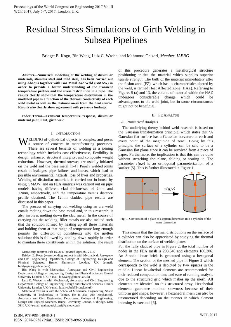
C. Weld Direction - Nomenclature
The usual concept of 90 degrees, 180 degrees, 270
degrees and 360 degrees has been used in a clockwise
manner to describe the direction of the weld, as well as the 3
o‟clock, 6 o‟clock, 9 o‟clock and 12 o‟clock convention.
Fig.6. A representation of the pipe rotation and nomenclature of 90, 180,
270 and 360 degrees
Figure 7 illustrates the 45, 135, 225 and 315-degree
reference system, which is obtained by simply rotating the
cross-section of the pipe in Figure 6 through an angle of 45
degrees in the clockwise direction.
Fig. 7. A representation of the pipe rotation and nomenclature of 45, 135,
225 and 315 degrees
The above style of representation of a welding direction is
known as 1:30 hours, 4:30 hours, 7:30 hours and 10:30
hours face of a clock using a temporal connotation.
Representing the four positions of interest on the pipe
circumference onto a plate, following the Gaussian
transformation principle, the following output is obtained as
shown in Figure 8. This implies that different weld
directions can also be represented on a plane surface as
shown on the 2D plate in Figure 8.
Proceedings of the World Congress on Engineering 2017 Vol II WCE 2017, July 5-7, 2017, London, U.K.
ISBN: 978-988-14048-3-1 ISSN: 2078-0958 (Print); ISSN: 2078-0966 (Online)
WCE 2017
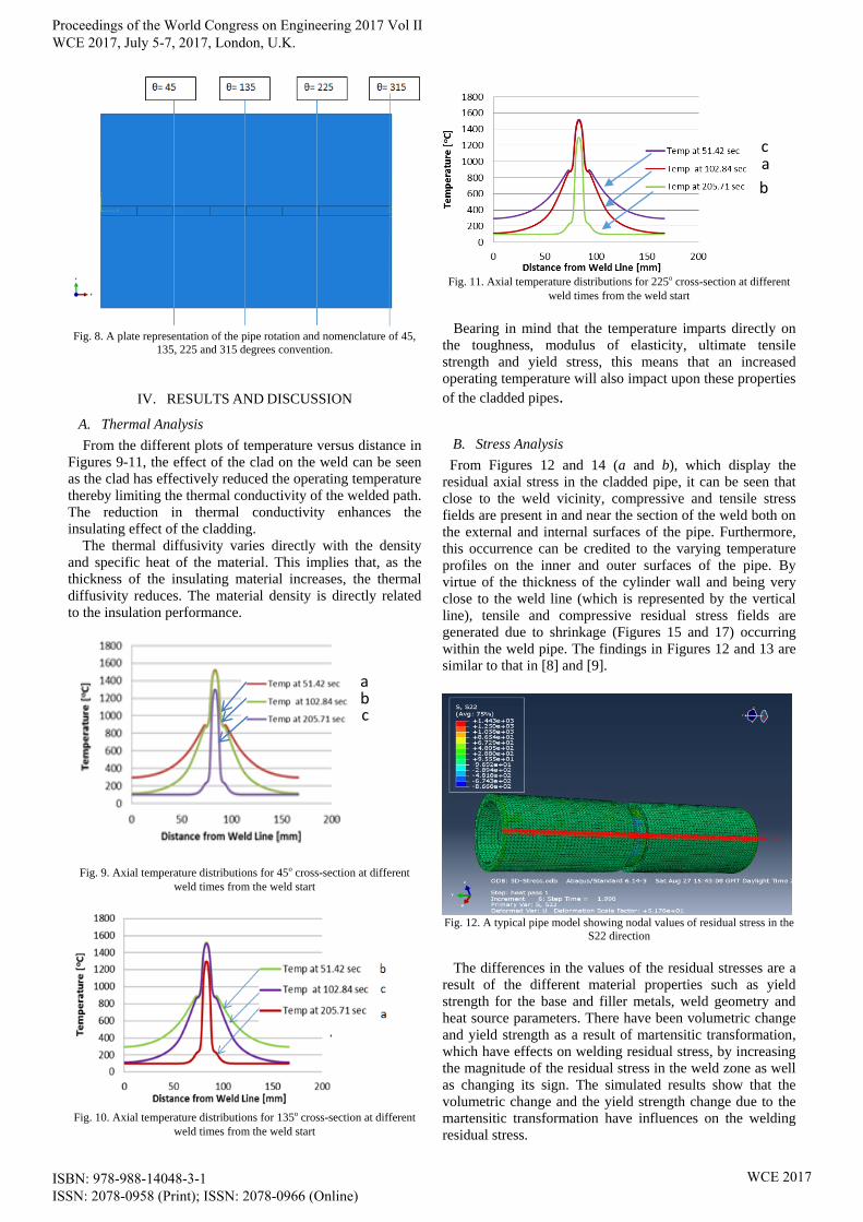
Fig. 8. A plate representation of the pipe rotation and nomenclature of 45,
135, 225 and 315 degrees convention.
IV. RESULTS AND DISCUSSION
A. Thermal Analysis
From the different plots of temperature versus distance in
Figures 9-11, the effect of the clad on the weld can be seen
as the clad has effectively reduced the operating temperature
thereby limiting the thermal conductivity of the welded path.
The reduction in thermal conductivity enhances the
insulating effect of the cladding.
The thermal diffusivity varies directly with the density
and specific heat of the material. This implies that, as the
thickness of the insulating material increases, the thermal
diffusivity reduces. The material density is directly related
to the insulation performance.
Fig. 9. Axial temperature distributions for 45o cross-section at different
weld times from the weld start
Fig. 10. Axial temperature distributions for 135o cross-section at different
weld times from the weld start
Fig. 11. Axial temperature distributions for 225o cross-section at different
weld times from the weld start
Bearing in mind that the temperature imparts directly on
the toughness, modulus of elasticity, ultimate tensile
strength and yield stress, this means that an increased
operating temperature will also impact upon these properties
of the cladded pipes.
B. Stress Analysis
From Figures 12 and 14 (a and b), which display the
residual axial stress in the cladded pipe, it can be seen that
close to the weld vicinity, compressive and tensile stress
fields are present in and near the section of the weld both on
the external and internal surfaces of the pipe. Furthermore,
this occurrence can be credited to the varying temperature
profiles on the inner and outer surfaces of the pipe. By
virtue of the thickness of the cylinder wall and being very
close to the weld line (which is represented by the vertical
line), tensile and compressive residual stress fields are
generated due to shrinkage (Figures 15 and 17) occurring
within the weld pipe. The findings in Figures 12 and 13 are
similar to that in [8] and [9].
Fig. 12. A typical pipe model showing nodal values of residual stress in the
S22 direction
The differences in the values of the residual stresses are a
result of the different material properties such as yield
strength for the base and filler metals, weld geometry and
heat source parameters. There have been volumetric change
and yield strength as a result of martensitic transformation,
which have effects on welding residual stress, by increasing
the magnitude of the residual stress in the weld zone as well
as changing its sign. The simulated results show that the
volumetric change and the yield strength change due to the
martensitic transformation have influences on the welding
residual stress.
a b c
b
c a
Proceedings of the World Congress on Engineering 2017 Vol II WCE 2017, July 5-7, 2017, London, U.K.
ISBN: 978-988-14048-3-1 ISSN: 2078-0958 (Print); ISSN: 2078-0966 (Online)
WCE 2017

Fig. 13. Welded plates showing residual tensile stress (underneath - inside
pipe) and compressive stress (above – outer surface of pipe).
Fig. 14. (a) Residual axial stresses on the inner surface and in S22 direction
of the HAZ of the 12 mm clad pipes
Fig. 14. (b) Residual axial stresses versus distance curve on the outer
surface of the HAZ of the 12 mm clad pipes
C. Radial Shrinkage
Fig. 15. A typical pipe model showing nodal readings for radial shrinkage
Fig. 16. Radial shrinkage versus normalized distance curve on the outer
surface of the 12 mm clad pipe end
When the weldment cools down, there is usually an axial
inclination of the constraint free end of the pipe taking
place.The thickness of the pipe is considered for the radial
shrinkage and measured for four different increments, so
that the shrinkage in thickness could be appreciated as
shown in Figure 15. At a tilt angle of 45 degrees, the radial
shrinkage is 0.022mm, and similarly at at an angle of 27.5
degrees, the radial shrinkage is 0.010mm.
D. Axial Shrinkage
Fig. 17. A typical pipe model showing nodal points for axial shrinkage
Fig. 18. Axial shrinkage versus normalized distance curve on the outer
surface of the HAZ of the 12 mm clad pipes
Proceedings of the World Congress on Engineering 2017 Vol II WCE 2017, July 5-7, 2017, London, U.K.
ISBN: 978-988-14048-3-1 ISSN: 2078-0958 (Print); ISSN: 2078-0966 (Online)
WCE 2017

For four different increments of the axial lenght, the
shrinkage is measured and plotted against the normalized
distance from the weld path. The axial shrinkage at lower
increments is slightly different from those at higher
increments, because there are high thermal gradients
experienced during butt welding leading to residual stress
and discrepancy in hardness, hence a creep effect is
observed at higher increments.
V. CONCLUSION
From the various plots of temperature versus distance
along the path of weld propagation, it has been observed that
the distribution of heat follows a unique pattern which has
been displayed in Figures 9 to 11, with the different HAZ
being taken into account. The peaks displayed in the plots
correspond to the immediate vicinity of the weld, with the
number and magnitude of the peaks increasing as the
cumulative quantity of heat is dispelled within the
weldment, and likewise decreasing the further away one
goes form the region of the weld.
From the results of the simulated axial stress and the
residual axial stress distributions on the inner surface of the
pipe, the following can be deduced:
1. Close to the region of weld region, comprehensive
axial, radial and hoop stresses can be observed but
farther away from the weld region, tensile stresses
become the trend.
2. Also, due to the symmetry across the weld line WL,
the axial stresses are symmetric in nature.
3. The radial and axial shrinkage effects on the 12mm
cladded pipe also agree with findings from the
thermal analysis, tensile stress curve and
microstructures of weld.
4. Results from the literature further confirm the
validity of the simulations carried out in this
research.
ACKNOWLEDGMENT
The authors want to express their gratitude to Brunel
University London for the facilities provided and conducive
research environment. The first author also thanks The Petroleum Technology
Development Fund (PTDF) for their funding and support through which this research has been made possible.
REFERENCES
[1] S. Lampman, “Weld Integrity and Performance”, ASM
International, 2001.
[2] J.A. Goldak, “Computational Welding Mechanics”, Springer,
2005.
[3] A.G. Youtsos, “Residual Stress and its Effects on Fatigue and
Fracture”, Springer, 2006.
[4] E. Muhammad, “Analysis of Residual Stresses and
Distortions in Circumferentially Welded Thin-Walled
Cylinders”, National University of Science and Technology,
Pakistan, 2008.
[5] M.E. EDU, “Gaussian Curvature”, retrieved from Math ETSU
EDU, December 29, 2016.
[6] C.P. Stone, P. Omnes, R.V.P Rezende, H. Grimm-Strele and
R.E Bensow, www.researchgate.net:
https://www.researchgate.net/post/Can_somebody_outline_th
e_advantages_of_utilizing_a_hexahedral_mesh_as_compared
_to_a_tetrahedral_mesh2, retrieved September 12, 2016.
[7] D.S. Sun, Q. Liu, M. Brandt, M. Janardhana and G. Clark,
“Microstructure and Mechanical Properties of Laser Cladding
Repair of AISI 4340 Steel”, International Congress of the
Aeronautical Sciences, pp. 1-9, 2012.
[8] N.U. Dar, E.M. Qureshi and M.M.I. Hammouda, “Analysis of
weld-induced residual stresses and distortions in thin-walled
cylinders”, Journal of Mechanical Science and Technology,
Vol. 23, pp. 1118-1131, 2009.
[9] P.K. Sinha, R. Islam, C. Prasad and M. Kaleem, “Analysis of
residual stresses and distortions in girth-welded Carbon steel
Proceedings of the World Congress on Engineering 2017 Vol II WCE 2017, July 5-7, 2017, London, U.K.
ISBN: 978-988-14048-3-1 ISSN: 2078-0958 (Print); ISSN: 2078-0966 (Online)
WCE 2017