resource allocation in visible light communication ... · resource allocation in visible light...
TRANSCRIPT

Resource Allocation in Visible Light Communication NetworksNOMA vs. OFDMA Transmission Techniques
Eirini Eleni Tsiropoulou, Iakovos Gialagkolidis, Panagiotis Vamvakas, and Symeon Papavassiliou
Institute of Communications & Computer Systems (ICCS)School of Electrical & Computer EngineeringNational Technical University of Athens (NTUA)
Erik Jonsson School of Engineering School & Computer ScienceUniversity of Texas at Dallas
1

2
Presentation Agenda
Introductory Remarks
Paper Contribution
OFDMA vs. NOMA
Optical Access Point Selection
Utility Functions
Problem Formulation and Solution Approach
NOAPRA Algorithm
Numerical Results
Takeaways
1.
2.
3.
4.
5.
6.
7.
8.
9.
10.
VPANs Topology and System Model

3
Presentation Agenda
Introductory Remarks
Paper Contribution
OFDMA vs. NOMA
Optical Access Point Selection
Utility Functions
Problem Formulation and Solution Approach
NOAPRA Algorithm
Numerical Results
Takeaways
1.
2.
3.
4.
5.
6.
7.
8.
9.
10.
VPANs Topology and System Model

4
Introductory Remarks
Visible Light Communications Personal Area Networks (VPANs)
• The communication signal is encoded on top of the illumination light
• Energy saving – “green” communication
• High Speed Connectivity Potential
• No health hazards, reduced interference and low transmission power at almost no cost
Resource Allocation
Distributed Approach • Optimal OAPs‘ Selection within the users, Resource Blocks (RBs) and Uplink Transmission Power allocation based on Maximum Gain Policy and Utility Maximization
• Not centrally determined: the decision lies at the mobile terminals
5
Presentation Agenda
Introductory Remarks
Paper Contribution
OFDMA vs. NOMA
Optical Access Point Selection
Utility Functions
Problem Formulation and Solution Approach
NOAPRA Algorithm
Numerical Results
Takeaways
1.
2.
3.
4.
5.
6.
7.
8.
9.
10.
VPANs Topology and System Model

6
Paper Contribution
Topology Optimization and Optimized User Transmission
Self Optimization
Power Allocation in the Uplink of VPANs
NOMA Extensive Comparisons
• OAP selection • Uplink Transmission Power Allocation
• The users optimally determine their transmission parameters irrespective of the selected transmission technique
• One of the first approaches in literature, so far only downlink transmission was examined
• Presentation of NOMA (Non Orthogonal Multiple Access) as a new promising transmission technique for resource allocation in the 5G networking era
• NOMA is in depth compared with OFDMA (Orthogonal Frequency Division Multiple Access) – Advantages and Disadvantages -Conclusions

7
Presentation Agenda
Introductory Remarks
Paper Contribution
OFDMA vs. NOMA
Optical Access Point Selection
Utility Functions
Problem Formulation and Solution Approach
NOAPRA Algorithm
Numerical Results
Takeaways
1.
2.
3.
4.
5.
6.
7.
8.
9.
10.
VPANs Topology and System Model

8
VPANs Topology & System Model
• Multi-cell VPAN network consisting of
• A spectrum of total bandwidth W is devoted to each OAP
T OAPs
U Mobile Users
1,2,...,t T T
1,2,...,u U U
• Each user u communicates with an OAP t via a communication link
• Line of Sight (LOS) between the user and the OAP:
A: photodetector area
φ: irradiance angleTs(ψ): signal transmission coefficient of an optical filterψ: angle of incidencem: order of Lambertian emissiong(ψ): gain of an optical concentratord: distance between the OAP and the user
,l u t
Simple VPAN topology
2,
1cos cos , 0
2
0,
m
s cu t
m AT g
H d
otherwise

9
Presentation Agenda
Introductory Remarks
Paper Contribution
OFDMA vs. NOMA
Optical Access Point Selection
Utility Functions
Problem Formulation and Solution Approach
NOAPRA Algorithm
Numerical Results
Takeaways
1.
2.
3.
4.
5.
6.
7.
8.
9.
10.
VPANs Topology and System Model
10
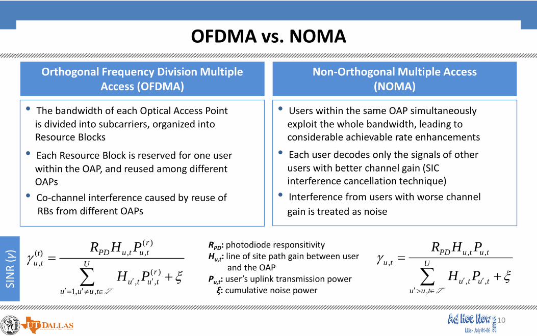
OFDMA vs. NOMA
Orthogonal Frequency Division Multiple Access (OFDMA)
Non-Orthogonal Multiple Access (NOMA)
• The bandwidth of each Optical Access Point is divided into subcarriers, organized into Resource Blocks
• Each Resource Block is reserved for one userwithin the OAP, and reused among differentOAPs
• Co-channel interference caused by reuse ofRBs from different OAPs
• Users within the same OAP simultaneouslyexploit the whole bandwidth, leading to considerable achievable rate enhancements
• Each user decodes only the signals of otherusers with better channel gain (SIC interference cancellation technique)
• Interference from users with worse channel
gain is treated as noise
( )
, ,(r)
,( )
, ,
1, ,
r
PD u t u t
u t Ur
u t u t
u u u t
R H P
H P
T
, ,
,
, ,
,
PD u t u t
u t U
u t u t
u u t
R H P
H P
T
SIN
R (γ)
RPD: photodiode responsitivityHu,t: line of site path gain between user
and the OAPPu,t: user’s uplink transmission power
ξ: cumulative noise power

11
Presentation Agenda
Introductory Remarks
Paper Contribution
OFDMA vs. NOMA
Optical Access Point Selection
Utility Functions
Problem Formulation and Solution Approach
NOAPRA Algorithm
Numerical Results
Takeaways
1.
2.
3.
4.
5.
6.
7.
8.
9.
10.
VPANs Topology and System Model
12
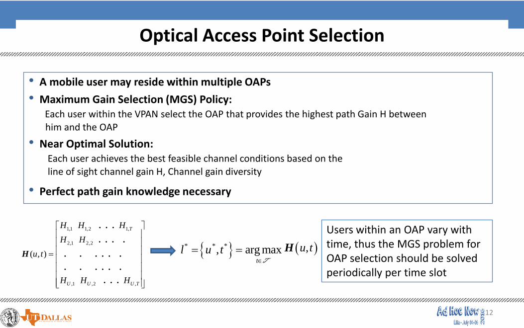
Optical Access Point Selection
• A mobile user may reside within multiple OAPs
• Maximum Gain Selection (MGS) Policy:Each user within the VPAN select the OAP that provides the highest path Gain H between him and the OAP
• Near Optimal Solution: Each user achieves the best feasible channel conditions based on the line of sight channel gain H, Channel gain diversity
• Perfect path gain knowledge necessary
1,1 1,2 1,
2,1 2,2
,1 ,2 ,
( , )
. . .
. . . .
H . . . . . .
. . . . . .
. . .
T
U U U T
H H H
H H
u t
H H H
* * *, arg maxt
l u t
T
,u tH
Users within an OAP vary with time, thus the MGS problem for OAP selection should be solved periodically per time slot

13
Presentation Agenda
Introductory Remarks
Paper Contribution
OFDMA vs. NOMA
Optical Access Point Selection
Utility Functions
Problem Formulation and Solution Approach
NOAPRA Algorithm
Numerical Results
Takeaways
1.
2.
3.
4.
5.
6.
7.
8.
9.
10.
VPANs Topology and System Model

14
Utility Functions
• Reflect users’ degree of satisfaction as a result of their actions
• A user targets at transmitting with low uplink transmission power:
Enhanced battery life
Less interference in the multi-cell VPAN environment
• Satisfaction increases with high transmission data rate and lower transmission power values
• Utility functions show the trade-off between the among parameters
,
,
,
,
,
,
:
:
r
u u tr
u t r
t u t
u u t
u t
u t
W fOFDMA U
N P
W fNOMA U
P
Nt: number of users within the OAPW: OAP’s bandwidthfu(∙): efficiency function - represents the probability of
successful packet transmission
Uti
lity
Fun
ctio
ns

15
Presentation Agenda
Introductory Remarks
Paper Contribution
OFDMA vs. NOMA
Optical Access Point Selection
Utility Functions
Problem Formulation and Solution Approach
NOAPRA Algorithm
Numerical Results
Takeaways
1.
2.
3.
4.
5.
6.
7.
8.
9.
10.
VPANs Topology and System Model

16
Problem Formulation and Solution Approach (1/2)
ObjectiveEach user acting selfishly targets at maximizing his overall perceived satisfaction (utility) through an optimally determined transmission power value via a distributed approach
Uplink Power
AllocationProblem
Formulation
,,
, , , ,
,
, , ,
,
: max , : max ,
. . 0 . . 0
r
-u,t -u,t P P
ru tu t
r r
u t u t u t u tPP
Max
r u t Max
u t u t u t
u t
OFDMA U P NOMA U P
Ps t P s t P P
R
The first approach towardsuplink transmission powerallocation in VPANs alongsideQoS provisioning
Optimization Solution
Approach
,,
, ,
, ,
,,
, ,
, ,
0 0
. 0 0
rru u t r ru t
u t u u tr r
u t u t
u u tu t
u t u u t
u t u t
fUf
P
fUresp f
P
First order derivative
of the utilities:
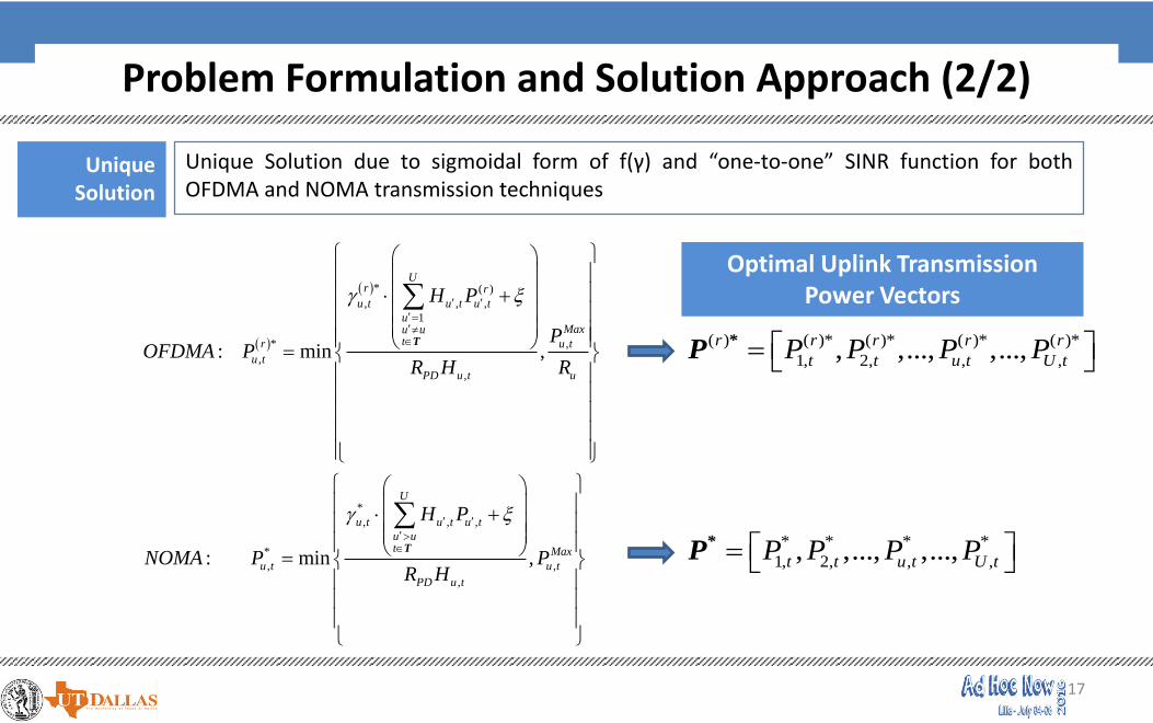
17
Unique Solution due to sigmoidal form of f(γ) and “one-to-one” SINR function for bothOFDMA and NOMA transmission techniques
Unique Solution
* ( )
, , ,
1
* ,
,
,
*
, , ,
*
, ,
,
: min ,
: min ,
Ur r
u t u t u t
uMaxu u
tr u t
u t
PD u t u
U
u t u t u t
u ut Max
u t u t
PD u t
H P
POFDMA P
R H R
H P
NOMA P PR H
T
T
( ) ( )* ( )* ( )* ( )*
1, 2, , ,, ,..., ,...,r r r r r
t t u t U tP P P P *
P
* * * *
1, 2, , ,, ,..., ,...,t t u t U tP P P P *
P
Optimal Uplink Transmission Power Vectors
Problem Formulation and Solution Approach (2/2)

18
Presentation Agenda
Introductory Remarks
Paper Contribution
OFDMA vs. NOMA
Optical Access Point Selection
Utility Functions
Problem Formulation and Solution Approach
NOAPRA Algorithm
Numerical Results
Takeaways
1.
2.
3.
4.
5.
6.
7.
8.
9.
10.
VPANs Topology and System Model

19
NOAPRA Algorithm (1/2)
NOAPRANon-Cooperative OAP Selection and Resource Allocation Algorithm:Decentralized, iterative, distributed, and low complexity - divided in two parts
OA
P S
ele
ctio
n P
art
Based on Maximum Gain Selection Policy, the Matrix H(u,t) is created, given perfect knowledge of path gain information. Set k=1 and U(0)={1,2,…,U}
Each user u* connects to the OAP t, via creating a communication link based on the highest path gain Hu,t
* *
* * *
,
, arg maxu t
l u t
U T
,u tH
Delete user u* from the overall set of users:
U(k+1)= U(k)-{u*}
If then stop. Otherwise go to Step 2)1( kU
Step A 1
Step A2
Step A3
Step A4

20
NOAPRA Algorithm (2/2)R
eso
urc
e A
lloca
tio
n P
art
Each OAP is aware of the number of users residing within it (i.e., U)
If R=U: one Resource Block is allocated per userRr Uu
Step B1
Step B2
Each user within an OAP initially transmits with a randomly selected feasible uplink transmission power and set k=0:
(OFDMA) (NOMA) ,*(r)(0)
,
,
0
Max
u t
u t
u t
PP
R *(0)
, ,0 Max
u t u tP P
The controller collects the information and each OAP announces the overall interference to the users. Each one user computes his sensed interference
Given the overall interference, each user updates his uplink transmission power. Set k=k+1
If (resp. ), e.g., then Stop Otherwise go to step 2.
*(r)( 1) *(r)( )
, ,
k k
u t u tP P *( 1) *( )
, ,
k k
u t u tP P 510
Step C1
Step C2
Step C3
Step C4
RB
’s
Allo
cati
on
(O
FDM
A)
Up
link
Tran
smis
sio
nPo
wer
Allo
cati
on

21
Presentation Agenda
Introductory Remarks
Paper Contribution
OFDMA vs. NOMA
Optical Access Point Selection
Utility Functions
Problem Formulation and Solution Approach
NOAPRA Algorithm
Numerical Results
Takeaways
1.
2.
3.
4.
5.
6.
7.
8.
9.
10.
VPANs Topology and System Model

22
Numerical Results
Simulation Scenario
• VPAN network with 8 OAPs within a room of size 10m x 6m x 3m
• OFDMA: 7 Resource Blocks are available
• Pmax=1W
• WOAP=20 MHz
• Ntotal = 56 users
Case 1: Uniform Distribution(7 users per OAP)
Case 2: Non-Uniform Users’ Distribution

23
Users’ Average Uplink Transmission Power per OAP
Case 1: Uniform Distribution Case 2: Non-Uniform Distribution
• In OFDMA, uplink transmission power considerably increases in non uniform user distribution since users share the same resource blocks within different OAPs, causing much higher interference
• In NOMA, increase in uplink transmission power for non uniform distribution is smoother due to the interference cancellation technique

24
System’s Total Uplink Transmission Power and Rate for Increasing Number of Users
• In OFDMA, due to the fixed number of reusable RBs, the system cannot support more than 56 users, thus any additional users are rejected. Transmission power and rate remain constant
• In NOMA, the system can accommodate and serve a much larger number of users providing superior data rate potential
25
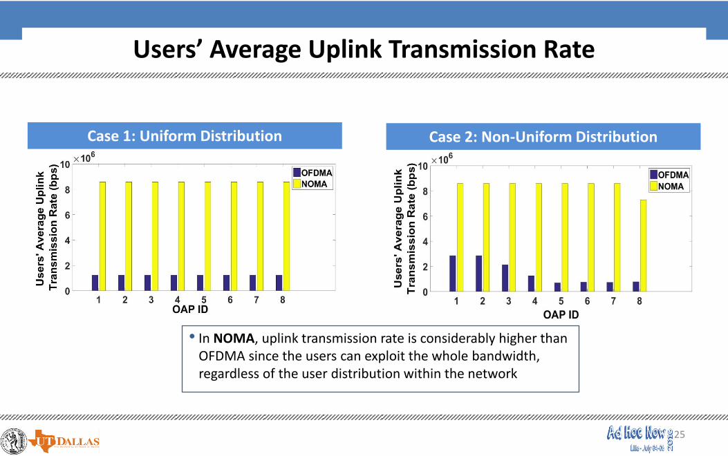
Users’ Average Uplink Transmission Rate
Case 1: Uniform Distribution Case 2: Non-Uniform Distribution
• In NOMA, uplink transmission rate is considerably higher than OFDMA since the users can exploit the whole bandwidth, regardless of the user distribution within the network

26
Presentation Agenda
Introductory Remarks
Paper Contribution
OFDMA vs. NOMA
Optical Access Point Selection
Utility Functions
Problem Formulation and Solution Approach
NOAPRA Algorithm
Numerical Results
Takeaways
1.
2.
3.
4.
5.
6.
7.
8.
9.
10.
VPANs Topology and System Model

27
Takeaways
• Optimal Optical Access Point selection alongside Transmission Power Allocation in the Uplink of VPANs under various transmission techniques
• Visible Light Communications a promising wireless technology:• Ultrahigh transmission speeds• Decreased users’ transmission power• No threat to human health
• NOMA• All users can simultaneously exploit the whole bandwidth• Considerable interference mitigation
• NOMA vs. OFDMA• NOMA can provide users with better service quality than OFDMA due to the interference mitigation (SIC)
technique, regardless of the user distribution with the network• Due to the absence of Resource Blocks per user, NOMA can sufficiently accommodate more users than
OFDMA

28
Resource Allocation in Visible Light Communication NetworksNOMA vs. OFDMA Transmission Techniques
Thank you for your attention!
e-mail: [email protected]