response modification factors of chevron-braced framesshb.skku.edu/_res/hibs/etc/18.pdf ·...
TRANSCRIPT

Engineering Structures 27 (2005) 285–300
www.elsevier.com/locate/engstruct
ths. Thedificationexcept in
Response modification factors of chevron-braced frames
Jinkoo Kim∗, Hyunhoon Choi
Department of Architectural Engineering, Sungkyunkwan University, Suwon, Republic of Korea
Received 5 June 2004; received in revised form 22 September 2004; accepted 16 October 2004
Available online 7 December 2004
Abstract
The overstrength, ductility, and the response modification factors of special concentric braced frames (SCBFs) and ordinary concentricbraced frames (OCBFs) were evaluated by performing pushover analysis of model structures with various stories and span lengresults were compared with those from nonlinear incremental dynamic analyses. According to the analysis results, the response mofactors of model structures computed from pushover analysis were generally smaller than the values given in the design codeslow-rise SCBFs. The results of incremental dynamic analysis generally matched well with those obtained from pushover analysis.© 2004 Published by Elsevier Ltd
Keywords: Special concentrically braced frames; Ordinary concentrically braced frames; Overstrength factors;Ductility factors; Response modification factors
dses
cithe
todevegtnin
sti
ialThed
ces o
uctd
tricssnetordraddedthe
nd
edheef
1. Introduction
Many seismic codes permit a reduction in design loataking advantage of the fact that the structures posssignificant reserve strength (overstrength) and capato dissipate energy (ductility). The overstrength and tductility are incorporated in structural design through a forcereduction factor or a response modification factor. The facrepresents the ratio of the forces that would develop unthe specified ground motion if the structure were to behaelastically to the prescribed design forces at the strenlimit state. Such a design concept is based on the assumptiothat well-detailed structures can develop lateral strengthexcess of their design strength and sustain large ineladeformation without collapse.
The role of the force reduction factor is essentin designing the earthquake load-resisting elements.response modification factors, which were first proposin the ATC 3-06 report [1], were in fact selected throughcommittee consensus based on the observed performanbuildings during past earthquakes and on the estimatesystem overstrength and damping, etc. [2].
∗ Corresponding author. Fax: +82 31 290 7570.E-mail address:[email protected] (J. Kim).
0141-0296/$ - see front matter © 2004 Published by Elsevier Ltddoi:10.1016/j.engstruct.2004.10.009
ctorlue
,s
y
rr
h
c
e
off
In documents such as ATC-19 [2] and ATC-34 [3], theresponse modification factor was calculated as the prodof three factors: overstrength factor, ductility factor, anredundancy factor. Osteraas [4] conducted a detailed studyof reserve strength of three structural systems:distributedmoment frames, perimeter moment frames, and concenbraced frames designed following the allowable stredesign provisions with seismic loads per UBC seismic zo4 and soiltype S2. They observed that the overstrength facof braced frames ranged between 2.8 and 2.2. Balenand Huang [5] found that the overstrength factors anthe ductility factors were almost the same for inverteV-braced and split X-braced frames. They also observthat the response modification factors decreased whennumber of stories increased. Forthree-, six-, and ten-storybraced frames, the response modification factor was fouto vary from 8.5 to 3.5. Maheri and Akbari [6] investigatedthe response modification factors of steel-braced reinforcconcrete framed dual systems. They found that taddition of steel X- and knee-braces increased the responsmodification factor significantly, and that the number ostories appeared to be the predominant variable. Accordingto the results of the above studies, the modification factorappears to be a period and applied load-dependent facontrary to seismic design codes prescribing a single va

286 J. Kim, H. Choi / Engineering Structures 27 (2005) 285–300
ss
oiao
ta
tll
es
hened
ot
mareFsueces
stsnds
e-li-
ualtio,ri-har-s:
ble-
s ofsre.offncealeres ofarof
l(,h.hesef
ic
r-
Notation
Ag Gross sectional area of bracesEs Elastic modulus of membersFcr Buckling stress of bracesFy Nominal yield stressKL Effective length of the compression members
such as columns and bracesPcr Buckling strength of bracesPn Nominal buckling strength of bracesPy Nominal axial yield force of bracesQb Unbalanced load between the tensile yield and
compressive buckling loads of bracesR Response modification factorRo Overstrength factorRr Redundancy factorRy Ratio of the expected yield stress and the
nominal yield stressRµ Ductility factorr Radius of gyrationVe Natural period of the structureVd Maximum seismic demand for elastic re-
sponseVy Design base shearT Base shear corresponding to the maximum
inelastic displacement∆1.5% Axial deformation of the brace at the
maximum interstory drift of 1.5% of storyheight
∆2.0% Axial deformation of the brace at themaximum interstory drift of 2.0% of storyheight
∆by Yield deformation of brace∆cb Buckling deformation of brace∆e Displacement of a corresponding elastic
structure∆max Maximum displacement of a structure∆y Yield displacement of a structureµ Displacement ductility ratio of a structureΦ Coefficient reflecting a soil conditionΦc Strength reduction factor of bracesθ Slope of braces
for all buildings with a specific structural system regardleof building height and earthquake load level.
IBC 2000 [7] divides concentric braced frames intordinary concentric braced frames (OCBFs) and specconcentric braced frames (SCBFs). The 1997 editionthe Seismic Provisions for Structural Steel Buildings [8]of AISC introduced the SCBF based on experimenand analytical works which showed that the post-bucklingbehavior of concentrically braced frames could be greaimproved by limiting width/thickness ratios of structuramembers and by maintaining closer spacing of stitch
lf
l
y
and special design and detailing of end connections. TAISC Seismic Provisions stipulate that a floor beam of aSCBF, which is intersected by braces, shall be designto support all the loads assuming that bracing is npresent. Also the beam needs to be designed consideringthe maximum unbalanced vertical load applied to the beaby the braces. Therefore the floor beams in an SCBFgenerally stronger than those in an OCBF, and SCBare expected to have increased ductility over OCBFs dto lesser strength degradation when compression brabuckle. Reflecting the difference, the IBC 2000 suggedifferent response modification factors for SCBFs aOCBFs,which are 6 and 5, respectively, although it providethe same overstrength factor, which is 2.
Previously the braced frame, originally developed to rsist wind load, was widely investigated for seismic appcation both experimentally [9–11] and analytically [12–15].The focus of those studies was on the strength of individmembers, such as slenderness ratio or width/thickness raor on the elastic/inelastic behavior of braced frames for vaous geometries or locations ofbraces. The previous researcfor evaluation of response modification factors has been cried out withlimited model structures and design variablefor example, braced frames in low seismic regions [5], low-story braced frames designed in accordance with allowastress designprocedure [4], and reinforced concrete structure strengthened by steel braces [6]. However no researchhas yet been conducted for comparison of behavior factorSCBFs and OCBFs designed for the same loading conditionfollowing the Load and Resistance Factor Design procedu
The present study focuses on the evaluationoverstrength, ductility, and response modification factors otwenty one SCBFs and nine OCBFs, designed in accordawith IBC 2000 and AISC Seismic Provisions for StructurSteel Buildings. Nonlinear static pushover analyses wcarried out to obtain such behavior factors, and the resultthe six-story SCBF were compared with those of nonlineincremental dynamic analyses to verify the resultsnonlinear static analysis procedure.
2. Response modification factors
Mazzolani and Piluso [16] addressed various theoreticaapproaches to compute the response modification factorq-factor), such as the maximum plastic deformation approachthe energy approach, and the low-cycle fatigue approacATC-19 proposed a simplified procedure to estimate tresponse modification factors, in which the responmodification factor, R, is calculated as the product othe three parameters that profoundly influence the seismresponse of structures:
R = RoRµ Rr (1)
whereRo is theoverstrength factor to account for the obsevation that the maximum lateral strength of a structure gen-erally exceeds its design strength. Recently FEMA-369 [17]
J. Kim, H. Choi / Engineering Structures 27 (2005) 285–300 287
inth,
antyesy ocy
tionctor-beor
r
nd, 9F
ned
dc-
0,as
ac-
c-
d tointscar-
meies.del
ssare
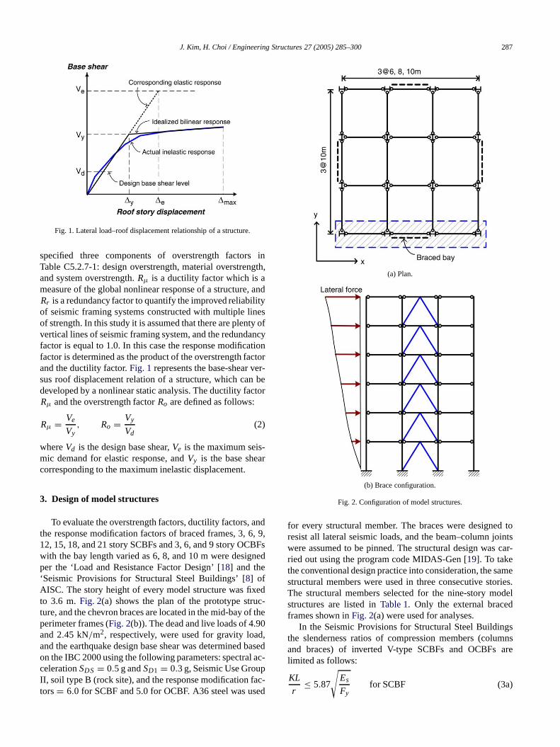
Fig. 1. Lateral load–roof displacement relationship of a structure.
specified three components of overstrength factorsTable C5.2.7-1: design overstrength, material overstrengand system overstrength.Rµ is a ductility factor which is ameasure of the global nonlinear response of a structure,Rr is a redundancy factor to quantify the improved reliabiliof seismic framing systems constructed with multiple linof strength. In this study it is assumed that there are plentvertical lines of seismic framing system, and the redundanfactor is equal to 1.0. In this case the response modificafactor is determined as the product of the overstrength faand the ductility factor.Fig. 1 represents the base-shear vesus roof displacement relation of a structure, which candeveloped by a nonlinear static analysis. The ductility factRµ and the overstrength factorRo are defined as follows:
Rµ = Ve
Vy, Ro = Vy
Vd(2)
whereVd is the design base shear,Ve is the maximum seis-mic demand for elastic response, andVy is the base sheacorresponding to the maximuminelastic displacement.
3. Design of model structures
To evaluate the overstrength factors, ductility factors, athe response modification factors of braced frames, 3, 612, 15, 18, and 21 story SCBFs and 3, 6, and 9 story OCBwith the bay length varied as 6, 8, and 10 m were desigper the ‘Load and Resistance Factor Design’ [18] and the‘Seismic Provisions for Structural Steel Buildings’ [8] ofAISC. The story height of every model structure was fixeto 3.6 m.Fig. 2(a) shows the plan of the prototype struture, and the chevron braces are located in the mid-bay of theperimeter frames (Fig. 2(b)). The dead and live loads of 4.9and 2.45 kN/m2, respectively, were used for gravity loadand the earthquake design base shear was determined bon the IBC 2000 using the following parameters: spectralcelerationSDS = 0.5 g andSD1 = 0.3 g, SeismicUse GroupII, soil type B (rock site), and the response modification fators= 6.0 for SCBF and 5.0 for OCBF. A36 steel was used
d
f
r
,s
ed
(a) Plan.
(b) Brace configuration.
Fig. 2. Configuration of model structures.
for every structural member. The braces were designeresist all lateral seismic loads, and the beam–column jowere assumed to be pinned. The structural design wasried out using the program code MIDAS-Gen [19]. To takethe conventional design practice into consideration, the sastructural members were used in three consecutive storThe structural members selected for the nine-story mostructures are listed inTable 1. Only the external bracedframes shown inFig. 2(a) were used for analyses.
In the Seismic Provisions for Structural Steel Buildingthe slenderness ratios of compression members (columnand braces) of inverted V-type SCBFs and OCBFslimited as follows:
KL
r≤ 5.87
√Es
Fyfor SCBF (3a)

288 J. Kim, H. Choi / Engineering Structures 27 (2005) 285–300
Table 1Sectional properties of nine-story model structures
Span length (m) Story Interior col. Exterior col. Interior beam Exterior beam Brace
(a) Special concentric braced frames
61–3 W14× 176 W10× 39 W27× 217 W16× 36 W8× 354–6 W14× 109 W10× 30 W27× 217 W16× 36 W8× 357–9 W14× 38 W10× 22 W27× 161 W16× 36 W8× 24
81–3 W14× 193 W10× 54 W36× 260 W16× 67 W10× 454–6 W14× 109 W10× 39 W36× 230 W16× 67 W8× 407–9 W14× 43 W10× 22 W36× 210 W16× 67 W8× 35
101–3 W14× 211 W12× 65 W36× 439 W18× 86 W8× 674–6 W14× 120 W12× 45 W36× 359 W18× 86 W8× 587–9 W14× 48 W12× 30 W36× 300 W18× 86 W8× 48
(b) Ordinary concentric braced frames
61–3 W14× 211 W10× 49 W14× 26 W16× 36 W8× 354–6 W14× 99 W10× 39 W14× 26 W16× 36 W8× 357–9 W14× 43 W10× 26 W14× 26 W16× 36 W8× 28
81–3 W14× 233 W10× 68 W14× 43 W16× 67 W8× 484–6 W14× 120 W10× 45 W14× 43 W16× 67 W8× 487–9 W14× 48 W10× 30 W14× 43 W16× 67 W8× 31
101–3 W14× 283 W12× 79 W14× 53 W18× 86 W10× 544–6 W14× 132 W12× 58 W14× 53 W18× 86 W10× 497–9 W14× 61 W10× 33 W14× 53 W18× 86 W10× 45
edk-
d
e
icthticnd-is
thes ofomic
thelhenbally
hetheitialThed to
KL
r≤ 4.23
√Es
Fyfor OCBF (3b)
wherer is the radius of gyration,KL is the effective length,Es is the elastic modulus, andFy is the yield stress ofthe members. The width-to-thickness ratio specified in theSeismic Provisionof AISC Table I-8-1 was also applied inthe design. For design of beams in SCBFs the unbalancload (Qb) between the tensile yield and compressive bucling loads of braces as well as the gravity loads was consid-ered. As shown inFig. 3, the unbalanced load was obtaineas follows with the buckling load taken to be 0.3ΦcPn:
Qb = (Ry Py − 0.3ΦcPn) × sinθ
= (Ry AgFy − 0.3ΦcAgFcr ) × sinθ (4)
where Ry is the ratio of the expected yield stress and thnominal yield stress(Fy), for which 1.5 is recommendedin the Seismic Provision [8]. Py is the nominal axial yieldforce,Pn is the nominal buckling strength,Φc is the strengthreduction factor,Fcr is the buckling stress of braces, andθ
is the slope of the brace as described inFig. 3.
4. Nonlinear static analysis of model structures
Mwafy and Elnashai [20] investigated the applicabilityof the inelastic static (pushover) analysis and the inelastdynamic analysis on 12 reinforced concrete buildings wivarious characteristics. They concluded that the stapushover analysis is more appropriate for low-rise ashort-period frame structures. For long-period or highrise structures, however, the inelastic dynamic analysis
Fig. 3. Unbalanced force due to buckling of compression brace.
preferable due to the participation of higher modes. In thisstudy the pushover analysis was employed to obtaininelastic responses of model structures, and the resultthe six-story SCBF were compared with those obtained frdynamic analyses to verify the applicability of the statprocedure.
4.1. Pushover analysis
Eigenvalue analyses were conducted first usingprogram DRAIN-2DX [21] to determine the elastic naturaperiods and mode shapes of the model structures. Tpushover analyses were carried out to evaluate the gloyield limit state and the structural capacity by progressiveincreasing the lateral story forces proportional to tfundamental mode shape. The post-yield stiffness ofbeams and columns was assumed to be 2% of the instiffness, and that of the braces was assumed to be zero.expected yield stress of structural members was assume

J. Kim, H. Choi / Engineering Structures 27 (2005) 285–300 289
of
by
d-
fnes
d
e-
ngfd
thegth.as
turey at
d toureutlsoashe
anre
eof
(a) Tension brace.
(b) Compression brace.
Fig. 4. Simplified analysis model for force–displacement relationshipbrace.
Fig. 5. Modeling ofP–delta effect.
be 1.5 times the nominal yield stress as recommendedthe Seismic Provisions for Structural Steel Buildings [8] forASTM A36 steel. The phenomenological model proposeby Jain and Goel, which was also presented in FEMA274 [22], was used for modeling nonlinear behavior obraces (Fig. 4). The post-buckling residual compressioforce is set to be 20% of the buckling load as given in Tabl5–8 of FEMA-273 [23]. The P–∆ effect was considered byemploying the dummy column, shown inFig. 5, which issubjected to the gravity load of interior frames not includein the analysis models.
Fig. 6(a) and (b) show the pushover curves of the ninstory SCBF and OCBF structures, respectively. In the baseshear–roof displacement curves, the points correspondingto the design base shear, the first buckling and yieldiof braces, maximum inter-story drift of 1.5% and 2.0% ostory height are indicated. In the figures it can be observe
(a) SCBF.
(b) OCBF.
Fig. 6. Pushover curves of the nine-story structures.
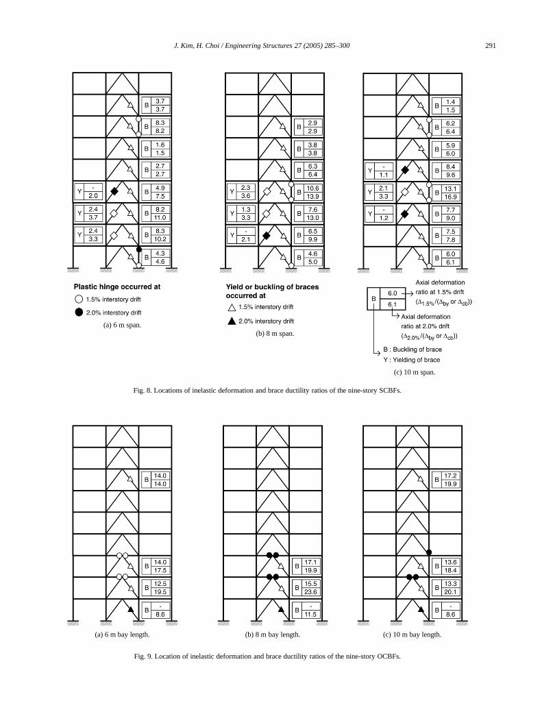
that the stiffness of the SCBF decreases slightly bybuckling of a compressive brace, and the maximum strenis reached slightly before the first yielding of a tensile braceThe maximum strength is about three times as highthe design base shear. However in the OCBF, the strucbehaves elastically and then the strength drops sharplthe occurrence of the first buckling of the compressionbrace and the subsequent yielding of beams connectethe buckled brace. The lateral strength of the structslightly increases with further redistribution of loads, bdrops again at buckling of braces in other stories. It acan be observed both in the SCBF and OCBF thatthe span length increases the stiffness and strength of tsystem increase.Fig. 7 shows the inter-story drift ratio ofthe nine-story structure with 6 m span length, where it cbe observed that large drift occurs in lower stories whebuckling occurs in braces.Fig. 8depicts the state of damagin structural members and the ductility ratio in bracesthe nine-story SCBFs. It canbe observed that when the

290 J. Kim, H. Choi / Engineering Structures 27 (2005) 285–300
ylerehn
n
de
andry
etlyr
stion
ynd.
lsor
erer-
a-e ofldwry
alFor
sisut
of
daterrgth
resr ofchgtheaseedialthBFsting
(a) SCBF.
(b) OCBF.
Fig. 7. Inter-story drift ratio of the nine-story structures with 6 m spanlength.
maximum inter-story drift reaches 1.5% of the storheight most of the braces under compression buckNo plastic hinge can be observed in beams which wedesigned considering the vertical unbalanced force. Tcorresponding results for OCBFs with the same height abay length are shown inFig. 9, which suggests that damageis concentrated in braces and beams located in the lowerthree stories. Compared to the SCBF, the ductility demain braces is much higher in the OCBF.
4.2. Failure state of braced frames
The failure criteria of a structure are generally definein two levels: local and global levels. Appendix I: Tentativguidelines for performance-based seismicengineering of the
.
ed
d
SEAOC-Blue Book [24] regulates thelimit state of SCBFsand OCBFs for the collapse prevention stage as 2.2%1.5% of the maximum story drift or as the maximum stoductility ratio of 5.0. In FEMA-356 [25] the maximum inter-story drift ratio of a braced frame is limited to 2.0% for thcollapse prevention performance level, which is significansmaller than the 5.0% story drift ratio recommended fomoment frames. In an element level, FEMA-356 regulatesthe acceptance criteria of tensile and compressive braceclassified as primary components in the collapse prevenstage as nine times the yield deformation(∆by) and seventimes the buckling deformation(∆cb), respectively. In thisstudy the global limit state of 2.0% maximum inter-stordrift ratio is used to define the collapse state of an SCBF, a1.5% of the maximum inter-story drift ratios for an OCBFAt the global limit state, the fracture limit state of eachmember is also checked. The local failure criteria are achecked at the 2.0% of the maximum drift ratio in OCBF focomparison.
Figs. 8and9 demonstrate that some of the braces undcompression reach a limiting state when the maximum intstory drift reaches 1.5% of the story height. Although notonetension brace reached a limiting state, it would be resonable to consider some of them already failed becausthe bi-directional nature of earthquakes. However it shoube noted that a global failure may not occur by failure of febraces. Therefore to consider 2.0% of maximum inter-stodrift ratio for the SCBF and 1.5% for the OCBF as a globlimiting state of a braced frame appears to be reasonable.comparison the behavior factors at 2.0% drift ratio were alsoobtained in the OCBF.
4.3. Overstrength factors
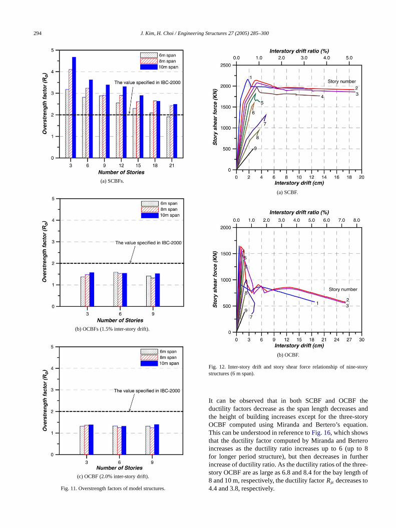
The capacity envelopes obtained from pushover analywere utilized to evaluate overstrength factors. To find othe yield point, a straight line was drawn in such a waythat the area under the original curve is equal to thatthe idealized one as recommended in FEMA-356 [25] forstructures with negative post-yield stiffness (Fig. 10). Itis recommended that the yield strength of the idealizeforce–displacement curve should not be taken as grethan the maximum base shear force of the actual pushovecurve. The base shear at yield and the maximum strenof all the analysis model structures are presented inTable 2,and the overstrength factors are plotted inFig. 11. It can beobserved that the overstrength factors of SCBF structuincrease as the span length increases and the numbestories decreases. However those of OCBFs are not muaffected by the change in span length. As the span lenincreases, the gravity load and the design base shear incrif other design conditions remain the same. Also increasare: (i) the bending moment in beams and columns; (ii) axload in columns; and consequently (iii) the nominal strengof structural members. The increase in base shear in SCresults in increase in brace size, the unbalanced force ac
J. Kim, H. Choi / Engineering Structures 27 (2005) 285–300 291
(a) 6 m span.(b) 8 m span.
(c) 10 m span.
Fig. 8. Locations of inelastic deformation and brace ductility ratios of the nine-story SCBFs.
(a) 6 m bay length. (b) 8 m bay length. (c) 10 m bay length.
Fig. 9. Location of inelastic deformation and brace ductility ratios of the nine-story OCBFs.

292 J. Kim, H. Choi / Engineering Structures 27 (2005) 285–300
nthes
thhedthf
nge
eorFtoar
. ItF
hFAomceofin
er
e
isnelthhetethgttmbe
ntaisot theisteis
tee
m
s.
on the floor beams, the size of beams, and consequethe overstrength factors. However in OCBFs, in which tunbalanced force is not considered, the increase in crosectional area of structural membersis not as significantas in SCBFs. For example, when the span lengths ofthree-story SCBF and OCBF increase from 6 to 8 m, tincrease in design base shearis almost the same (33.3% an33.6%, respectively). However the increase in yield strengin SCBF, which is 72.2%, is significantly larger than that othe OCBF, whichis 43.6%. This explains the observatiothat the increase in overstrength factors in SCBFs is larthan that in OCBFs when the span length increases.
In SCBFs, the overstrength factors are generally largthan the value specified in IBC-2000, which is 2, except fthe 21-story structure with span length of 6 m. In OCBstructures, however, the overstrength factors turned outbe smaller than the specified value of 2. These resultscompatible with the FEMA-369 report [17] which states thatoverstrength factors for braced frames vary from 1.5 to 2.0also can be observed that the overstrength factors of OCBestimated at the 1.5% inter-story drift ratio, are somewhatlarger than those estimated at the 2.0% inter-story drift. Tanalysis results show that the overstrength factors of SCBare about two to three times larger than those of OCBFs.mentioned earlier, the larger overstrength factors result frthe useof larger beams designed considering the unbalanforce in braces. This also contributes to the distributionplastic hinges in almost all stories in SCBFs, whereasOCBFs theplastic hinges are concentrated in a few lowstories as seen inFigs. 8and9. This implies that soon afterthe first buckling of a brace and consequent formation ofplastic hinges in the beam, the lateral-load resisting capacityof the OCBF structure decreases rapidly, resulting in lowoverstrength factors.
The overstrength factors of OCBFs obtained in thstudy are somewhat smaller than obtained by Uang aBertero [10] from the experiments of the 30%-scaled modwith slabs, which is 2.4. The larger value for overstrengfactor seems to be contributed from the participation of tslab in resisting the unbalanced force of braces. It is reporthat the composite action of a composite beam increasesbending stiffness about 10–15% and the bending strenabout 5–10% [13]. Therefore the results of the currenstudy for overstrength factors, which were obtained froanalytical study using bare frames without a slab, mayconsidered as a lower bound.
In IBC 2000 some special elements and componeare required to be designed for the special seismic locombinations in which the earthquake load effectmultiplied by the system overstrength factor. This is tensure that the elements have enough strength to resismaximum force transferred from the other elements of tlateral force resisting system. If the overstrength factorunderestimated, the transferred force is also underestimaand this may lead to unsafe design. Therefore prec
ly
s-
e
r
r
e
s,
ess
d
r
d
deh
sd
he
d;e
(a) Idealized curve for negative post-yield slope.
(b) Bilinear representation of nine-story OCBF (6 m span).
Fig. 10. Idealized force–displacement curve for braced frames.
estimation of the overstrength factor is essential to guaranseismic safety of structures.
4.4. Ductility factors
The ductility factorRµ was obtained using the systemductility factor µ by the procedure proposed by Newmarkand Hall [26] and Miranda and Bertero [27]. Newmarkand Hall proposed the following equations for the systeductility factors:
Rµ = 1.0 (T < 0.03 s)
Rµ = √2µ − 1 (0.12< T < 0.03 s)
Rµ = µ (T > 1.0 s)
(5)
whereT is the natural period of the structure. Miranda andBertero developed generalRµ–µ–T relationships using 124ground motions recorded on a wide range of soil condition

J. Kim, H. Choi / Engineering Structures 27 (2005) 285–300 293
Table 2Results of pushover analysis for model structures (Unit: kN, cm, s)
(a) Special concentric braced frames
Span length (m) # of stories3 6 9 12 15 18 21
6 Period 0.46 0.88 1.44 2.07 2.79 3.54 4.40Vd 413.64 677.37 749.66 805.57 851.79 891.51 926.52Vy 1312.35 1905.64 2156.55 2052.35 1956.65 1859.12 1763.84∆y 3.76 10.14 21.74 32.02 46.42 62.97 79.59∆ 10.52 17.60 36.80 46.64 64.69 86.03 104.00
8 Period 0.40 0.78 1.27 1.79 2.38 2.99 3.64Vd 551.49 903.17 999.52 1074.07 1135.68 1188.65 1235.36Vy 2260.00 2922.22 2908.47 3113.54 2962.59 3142.05 2997.25∆y 3.37 9.74 17.49 28.21 39.02 54.88 70.45∆ 9.96 18.24 32.61 45.58 60.56 76.10 89.81
10 Period 0.37 0.69 1.15 1.57 2.16 2.69 3.23Vd 689.39 1128.96 1249.42 1342.61 1419.60 1485.84 1544.20Vy 3220.49 4086.61 4228.91 4438.15 4109.37 3909.55 3837.53∆y 3.97 9.08 16.99 26.65 35.04 43.82 52.80∆ 10.26 17.80 30.21 45.32 57.62 68.93 80.10
(b) Ordinary concentric braced frames
Span length (m) # of stories3 6 91.5% Drift 2.0% Drift 1.5% Drift 2.0% Drift 1.5% Drift 2.0% Drift
6 Period 0.43 0.85 1.39Vd 537.75 886.70 988.53Vy 739.58 707.57 1406.47 1180.93 1397.30 1303.77∆y 1.29 1.24 5.95 4.99 11.70 10.92∆ 6.32 8.18 12.19 16.13 20.22 26.11
8 Period 0.42 0.73 1.20Vd 719.77 1187.84 1322.50Vy 1062.35 981.99 1825.24 1493.26 1743.65 1645.02∆y 1.25 1.16 4.19 3.43 7.95 7.49∆ 6.07 7.90 11.28 15.16 15.14 20.93
10 Period 0.37 0.66 1.12Vd 910.68 1502.87 1675.10Vy 1428.47 1261.42 2318.14 1981.09 2551.42 2339.41∆y 1.03 0.92 3.35 2.86 7.53 6.90∆ 5.94 7.80 11.15 14.88 18.14 24.23
d
nd
r
ofn
enen
f
esnroll.
The following equation is for a rock site:
Rµ = µ − 1
Φ+ 1
Φ = 1 + 1
10T − µT− 1
2Te−1.5(ln(T)−0.6)2
(6)
where Φ is a coefficient reflecting a soil condition. Thesystem ductility ratio µ is obtained by dividing theroof displacement at the limit state by the system yieldisplacement.
Fig. 12 plots the inter-story drift and story shear forcerelationship in each story of the nine-story SCBF andOCBF structures with span length of 6 m. Based othe figures the story ductility ratios were computed anpresented inFig. 13. It can be observed inFig. 13 that the
maximum story ductility ratio becomes 3.55 and 7.04 foSCBF and OCBF, respectively, when the maximuminter-story drift reaches 2% of the story height. In the caseOCBF, the story ductility ratio exceeds 5.0 specified iSEAOC [24] for the limit state of the collapse preventionperformance level. This is contributed not only from thbuckling of the braces but also from the plastic deformatioin beams caused by the unbalanced force betwethe tensile yielding and compressive buckling force obraces.
Figs. 14and15 show the system ductility factorRµ ofbraced frames when the maximum story drift ratio reach2.0% for the SCBF and 1.5 and 2.0% for the OCBF. Imost cases the factors computed by Miranda and Berteturned out to be larger than those by Newmark and Ha
294 J. Kim, H. Choi / Engineering Structures 27 (2005) 285–300
eandry.
o8
er-f
(a) SCBFs.
(b) OCBFs (1.5% inter-story drift).
(c) OCBF (2.0% inter-story drift).
Fig. 11. Overstrength factors of model structures.
(a) SCBF.
(b) OCBF.
Fig. 12. Inter-story drift and story shear force relationship of nine-storystructures (6 m span).
It can be observed that in both SCBF and OCBF thductility factors decrease as the span length decreasesthe height of building increases except for the three-stoOCBF computedusing Miranda and Bertero’s equationThis can be understood in reference toFig. 16, which showsthat the ductility factor computed by Miranda and Berterincreases as the ductility ratio increases up to 6 (up tofor longer period structure), but then decreases in furthincrease of ductility ratio. As the ductility ratios of the threestory OCBF are as largeas 6.8 and 8.4 for the bay length o8 and10m, respectively, the ductility factorRµ decreases to4.4 and 3.8, respectively.

J. Kim, H. Choi / Engineering Structures 27 (2005) 285–300 295
n
sed
ss
ndr
Cllth
erser-
eedery
d
ely.;gey.
(a) SCBF.
(b) OCBF.
Fig. 13. Story ductility ratios of the nine-story structures with 6 m spalength.
4.5. Response modification factors
The response modification factors, presented inFigs. 17and 18, are computed by multiplying the overstrengthand the ductility factors obtained in the previous sectionIn SCBF the response modification factors are obtainwhen the maximum inter-story drift ratio reaches 2.0%,while the factors at 1.5% and 2.0% inter-story drifts areobtained in OCBF. It can be observed that the responmodification factors decrease as the span length decreaand the height of the building increases. In the three- asix-story SCBF structures the response modification factoturns out to be larger than 6 which is prescribed in IB2000, and in higher structures the factors are generaless than 6. For OCBF only the three-story structure wi
.
ees
s
y
(a) Newmark and Hall.
(b) Miranda and Bertero.
Fig. 14. System ductility factors of SCBFs.
10 m bay length has response modification factors largthan the IBC 2000 specified value of 5. The responmodification factors obtained at 2.0% maximum intestory drift are slightly largerthan those obtained at 1.5%inter-story drift. Considering that most OCBFs reach thlimit state of the collapse prevention stage, as observin Figs. 9 and 13, it would be reasonable to compute thresponse modification factor at 1.5% maximum inter-stodrift.
The response modification factors for OCBFs obtainein this study are somewhat smaller than those obtained byBalendra and Huang [5] with 3-, 6-, and 10-story inverted-V-braced frames, which are 8.52, 5.23, and 3.74, respectivThe ductility factors are quite similar in both studieshowever the overstrength factors of their study, which ranfrom 2.48 to 5.57, are larger than those of the current stud

296 J. Kim, H. Choi / Engineering Structures 27 (2005) 285–300
(a) Newmark and Hall (1.5% drift). (b) Miranda and Bertero (1.5% drift).
(c) Newmark and Hall (2.0% drift). (d) Miranda and Bertero (2.0% drift).
Fig. 15. System ductility factors of OCBFs.
These differences can be explained by the difference inseismic load used in the structural design. The ratios ofbaseshear to seismic gravity load,Vb/Wg, of theiranalysismodels are 1.4%, 1.4%, and 2.2% for the 3-, 6-, and 10-story structures, respectively; while those of our models are12.5%, 10.2%, and 7.6% for the 3-, 6-, and 9-story OCBFstructures, respectively. This implies that their models areassumed to be located in a low-seismic region, while thestudy models of the current study are designed for higherseismic loads. These results match with findings of Jainand Navin [28] that the overstrength factors of structuresin a low-seismic region are five times as large as those inhigh-seismic region. Therefore it can be concluded that thestructure designed for relatively low seismic load tends tohave higher residual strength for seismic load.
-
are
e
5. Comparison with incremental dynamic analysisresults
A series of incremental dynamic analyses were performed until all the predefined limit states were exceededin order to verify the results of static analyses. Among thetime history records developed for the SAC project [29],six records which match well with the design spectrum(SDS = 0.5 g, SD1 = 0.3 g) were selected for dynamicanalyses. The response spectra and the design spectrumdepicted inFig. 19. Inelastic time-history analyses were car-ried out using the six-story SCBF model structure with 8 mspan length using the program SNAP-2DX [30], and thedynamic pushover envelopes were obtained by plotting thepoint corresponding to the maximum base shear and th

J. Kim, H. Choi / Engineering Structures 27 (2005) 285–300 297
l
dr-
e
d
rten
e
dse
dseseeldds.ae
reIn
y
fed
a
Fig. 16. Comparison of ductility factors computed from Newmark and Haland Miranda and Bertero’s equations.
maximum top-story displacement computed for each scalerecord. The intensities of the time history records were vaied by multiplying appropriatescaling factors. The dynamicpushover envelopes were compared with the static pushovcurve inFig. 20, which shows that the dynamic envelopesform upper bound for displacement larger than the yielpoint.
To obtain behavior factors, the six dynamic pushoveenvelopes were averaged and the average curve was fitinto a bi-linear curve. The overstrength factor obtained ithis way is 2.88 which is 11%smaller than the factorobtained from the static pushover curve. However thductility factor computed for each record using the Newmarkand Hall procedure ranges from 1.65 to 2.13 with themean value of 1.99, which is larger than 1.78 obtainefrom the static pushover curve. Consequently the responmodification factorresults in 5.76–6.14with the mean valueof 5.75, which is almost identical to the value obtained fromstatic pushover analysis (which is 5.74).
6. Conclusions
The overstrength,ductility, and the response modificationfactors of the 21 special concentric braced frames an9 ordinary concentric braced frames with various storieand span lengths were evaluated by performing pushovanalyses. Some of the results were compared with thofrom nonlinear incremental dynamic analyses. The modstructures were designed for relatively large seismic load anthe beam–column connections were assumed to be pinneso that the seismic load was resisted mainly by braceSuch design conditions are expected to produce somewhconservative results for response modification factors. Thresults of this study can be summarized as follows:
(1) The overstrength factors increased as the structuheight decreased and the span length increased.SCBFs, the factors turned out to be 1.9–3.17 for 6 m
r
d
r
t
(a) Newmark and Hall.
(b) Miranda and Bertero.
Fig. 17. Response modification factors of SCBFs.
span, 2.43–4.10 for 8 m span, and 2.49–4.67 for 10 mspan, which are generally larger than the IBC 2000specified value of 2.0. In OCBFs, however, the factorsranged between 1.32 to 1.59 (1.5% maximum inter-stordrift ratio) and 1.24 to 1.40 (2.0% drift ratio), which aresignificantly smaller than 2.0. The underestimation ooverstrength factors in design codes may lead to unsafdesign by underestimating the seismic force transferreto a critical element from the other elements of thelateral force resisting system.
(2) The ductility factors were obtained as 1.28–2.2(Newmark and Hall procedure) and 1.29–2.49 (Mirandand Bertero) for SCBFs with limit state of 2% maximuminter-story drift ratio, and as 1.73–3.24 (Newmarkand Hall) and 1.95–3.95 (Miranda and Bertero) forOCBFs with 1.5% maximum drift ratio. As in the caseof overstrength factors, the ductility factors increased

298 J. Kim, H. Choi / Engineering Structures 27 (2005) 285–300
(a) Newmark and Hall (1.5% drift). (b) Miranda and Bertero (1.5% drift).
(c) Newmark and Hall (2.0% drift). (d) Miranda and Bertero (2.0% drift).
Fig. 18. Response modification factors of OCBFs.
gt
endfor
gd
ngor
ryess.
byannset
ofhan0.veionigncingsent
as the structure height decreased and the bay lenincreased.
(3) The response modification factors were in the rang2.49–6.8 (6 m span), 3.01–9.08 (8 m span), a3.77–9.55 (10 m span) for SCBFs, and 2.44–5.09OCBFs when the Newmark and Hall procedure wasapplied to compute ductilityfactors. As the responsemodification factors were computed by multiplyinoverstrength and ductility factors, they also increaseas the structure height decreased and the span leincreased. In SCBFs the response modification factturned out to be smaller than the code-specified valueof 6.0 in most model structures except the three-stostructures. The response modification factors were lthan the code value of 5.0 in all OCBF model structure
h
s
ths
s
(4) The maximum base shear envelopes obtainedincremental dynamic analyses generally formedupper bound to the static pushover curve. The respomodification factors obtained from the two differenprocedures turned out to be similar.
It turned out that the earthquake-resisting capacitybraced frames, especially OCBFs, was generally less tthe level specified in a design code such as IBC 200However, considering the fact that braced frames hasuperior load-resisting capacity as long as the compressbraces do not buckle, it would be reasonable to desbrace frames as rather more strength based by reduthe response modification factor. In fact, the responmodification factors for the intermediate steel mome

J. Kim, H. Choi / Engineering Structures 27 (2005) 285–300 299
ed
re
d
nedre.
chrt
ns,
-d
gn.
elral
n
0,at
tedeel
f4,at
ke.nal
-
ers.
eel
9,
ralo;
.
se24.m
a-nt
s.
Fig. 19. Design spectrum and response spectra of selected earthquakerecords.
Fig. 20. Static and dynamic pushover curves of the six-story SCBF.
frames and the ordinary steel moment frames specifiin FEMA-302 [31] were 6 and 4, respectively; however,based on new findings from recent research, they wereduced to 4.5 and 3.5, respectively, in FEMA-368 [32].Also the response modification factors need to be definein various performance levelsconsidering seismic hazardlevels, number of stories, target ductility ratios, etc. Ithis regard further research still needs to be performconsidering various design variables to propose moreasonable behavior factors for concentric braced frames
Acknowledgement
This research was funded by the Korea ResearFoundation (R01-2002-000-00025-0). The financial suppois gratefullyacknowledged.
References
[1] ATC. Tentative provisions for the development of seismic regulatiofor buildings. ATC-3-06, Applied Technology Council, Redwood CityCalifornia, 1978:45–53.
[2] ATC. Structural response modification factors. ATC-19, AppliedTechnology Council, Redwood City, California, 1995:5–32.
[3] ATC. A critical review of current approaches to earthquakeresistant design. ATC-34, Applied Technology Council, RedwooCity, California, 1995:31–6.
[4] Osteraas JD. Strength and ductility considerations in seismic desiPh.D. dissertation, Stanford University, Stanford, California; 1990.
[5] Balendra T, Huang X. Overstrength and ductility factors for steframes designed according to BS 5950. Journal of StructuEngineering, ASCE 2003;129(8):1019–35.
[6] Maheri MR, Akbari R. Seismic behavior factor,R, for steel X-bracedand knee-braced RC buildings. Engineering Structures 2003;25(15):1505–13.
[7] ICC. International building code. International Code Council; 2000.[8] AISC. Seismic provisions for structural steel buildings. America
Institute of Steel Construction, Chicago, Illinois; 2002.[9] Black RG, Wenger WAB, Popov EP. Inelastic buckling of steel
struts under cyclic load reversals. Report No. UCB/EERC-80/4Earthquake Engineering Research Center, Univ. of CaliforniaBerkeley; 1980.
[10] Uang CM, Bertero VV. Earthquake simulation tests and associastudies of a 0.3-scale model of a 6-story concentrically braced ststructure. Report No. UCB/EERC-86/10, Earthquake EngineeringResearch Center, Univ. of California at Berkeley; 1986.
[11] Whittaker AS, Uang CM, Bertero VV. An experimental study othe behavior of dual steel systems. Report No. UCB/EERC-88/1Earthquake Engineering Research Center, Univ. of CaliforniaBerkeley; 1990.
[12] Khatib IF, Mahin SA, Pister KS. Seismic behavior of concentricallybraced steel frames. Report No. UCB/EERC-88/01, EarthquaEngineering Research Center, Univ. of California at Berkeley; 1988
[13] Roeder CW. Seismic behavior of concentrically braced frame. Jourof Structural Engineering, ASCE 1989;115(8):1837–56.
[14] Remennikov AM, Walpole WR. Analytical prediction of seismicbehavior for concentrically-braced steel systems. Earthquake Engineering and Structural Dynamics 1997;26(8):859–74.
[15] Tremblay R. Inelastic seismic response of steel bracing membJournal of Constructional SteelResearch 2002;58(5–8):665–701.
[16] Mazzolani FM, Piluso V. Theory and design of seismic resistant stframes. Spon: E & FN; 1996.
[17] BSSC. NEHRP Recommended provisions for seismicregulations fornew buildings and other structures; part 2: commentary. FEMA-36Building Seismic Safety Council, Washington, D.C.; 2001.
[18] AISC. Load and resistance factor design specification for structusteel buildings. American Institute of Steel Construction, Chicag1993.
[19] MIDAS/Gen Program. MIDAS/Gen-General structure design systemMIDAS/Gen Ver.5.7.1 analysisand design manual, MIDAS Informa-tion Technology, Co., Ltd.
[20] Mwafy AM, Elnashai AS. Static pushover versus dynamic collapanalysis of RC buildings. Engineering Structures 2001;23(5):407–
[21] Prakash V, Powell GH, Campbell S. DRAIN-2DX base progradescription and user guide. Report No. UCB/SEMM-1993/17,Department of Civil Engineering, University of California, Berkeley,1993.
[22] FEMA. NEHRP commentary on the guidelines for the seismic rehbilitation of buildings. FEMA-274, Federal Emergency ManagemeAgency, Washington, D.C.; 1997.
[23] FEMA. NEHRP guidelines for the seismic rehabilitation of buildingFEMA-273, Federal Emergency Management Agency, Washington,D.C.; 1997.
300 J. Kim, H. Choi / Engineering Structures 27 (2005) 285–300
.
n
I
.
ofl
rt
2,
8,
[24] SEAOC. Recommended lateral force requirements and commentaryStructural Engineers Association of California, 1997.
[25] FEMA. Prestandard and commentary for the seismic rehabilitatioof building. FEMA-356, Federal Emergency Management Agency,Washington, D.C.; 2000.
[26] Newmark NM, Hall WJ. Earthquake spectra and design. EERMonograph Series, Oakland (CA):Earthquake Engineering ResearchInstitute; 1982.
[27] Miranda E, Bertero VV. Evaluation of strength reduction factors forearthquake-resistant design. Earthquake Spectra 1994;10(2):357–79.
[28] Jain SK, Navin R. Seismic overstrength in reinforced concrete framesJournal of Structural Engineering, ASCE 1995;121(3):580–585.
[29] Somerville P, Smith H. Puriyamurthala S, Sun J. Developmentground motion time histories for phase 2 of the FEMA/SAC steeproject, SAC Joint Venture, SAC/BD-97/04; 1997.
[30] Rai D, Goel S, Firmansjah J. SNAP-2DX. Research RepoUMCEE96-21. Dept. Civil Eng., Univ. of Michigan, Ann Arbor, MI;1996.
[31] BSSC. NEHRP recommended provisions for seismicregulations fornew buildings and other structures; part 1: provisions. FEMA-30Building Seismic Safety Council, Washington, D.C.; 1997.
[32] BSSC. NEHRP recommended provisions for seismicregulations fornew buildings and other structures; part 1: provisions. FEMA-36Building Seismic Safety Council, Washington, D.C.; 2001.