retaining walls and geotechnical design to eurocode 7 summary
TRANSCRIPT

7/25/2019 Retaining Walls and Geotechnical Design to Eurocode 7 Summary
http://slidepdf.com/reader/full/retaining-walls-and-geotechnical-design-to-eurocode-7-summary 1/43
ICE Teesside Branch, NGG and IStructE
EUROCODE 7
Dr Ian Smith, Edinburgh Napier University
Retaining Walls and Geotechnical
Design to Eurocode 7
Dr Ian Smith
Head of School
School of Engineering and the Built Environment
Edinburgh Napier University

7/25/2019 Retaining Walls and Geotechnical Design to Eurocode 7 Summary
http://slidepdf.com/reader/full/retaining-walls-and-geotechnical-design-to-eurocode-7-summary 2/43
ICE Teesside Branch, NGG and IStructE
EUROCODE 7
Dr Ian Smith, Edinburgh Napier University
Geotechnical design by calculation
Processes involved:
Establish design values of actions and
geometrical data
Establish design values of ground
properties and resistances
Define limit that must not be exceeded
(e.g. bearing resistance)
Perform relevant geotechnical analysis
Show, by calculation, that limit will not be
exceeded

7/25/2019 Retaining Walls and Geotechnical Design to Eurocode 7 Summary
http://slidepdf.com/reader/full/retaining-walls-and-geotechnical-design-to-eurocode-7-summary 3/43
ICE Teesside Branch, NGG and IStructE
EUROCODE 7
Dr Ian Smith, Edinburgh Napier University
Geotechnical design by calculation
Actions:
• An action is given the general symbol, F.
• Actions can be permanent (persistent) or variable
(transient), accidental, or seismic.• Persistent actions are denoted by FG. Transient actions are
denoted by FQ.
• Persistent actions can be either “favourable” or
“unfavourable”.• Transient actions are always considered as unfavourable.

7/25/2019 Retaining Walls and Geotechnical Design to Eurocode 7 Summary
http://slidepdf.com/reader/full/retaining-walls-and-geotechnical-design-to-eurocode-7-summary 4/43
ICE Teesside Branch, NGG and IStructE
EUROCODE 7
Dr Ian Smith, Edinburgh Napier University
Geotechnical design by calculation
Ground properties:
• Geotechnical parameters should be established with consideration
given to published data and local and general experience…
• Clauses 2.4.3(3) to (6) give guidance on how the parametersshould be considered in the design process.
• Material properties are given the general symbol, X.
• Characteristic values of material properties are given the general
symbol, Xk.

7/25/2019 Retaining Walls and Geotechnical Design to Eurocode 7 Summary
http://slidepdf.com/reader/full/retaining-walls-and-geotechnical-design-to-eurocode-7-summary 5/43
ICE Teesside Branch, NGG and IStructE
EUROCODE 7
Dr Ian Smith, Edinburgh Napier University
Partial factors of safety
Provided in EN 1997-1
Nationally Determined Parameters (NDPs) provided in National Annexe
Symbols:
Actions: General: F Permanent: G
Transient: Q
Materials: General: M Soil properties: cu, , etc.
Resistance: General: R Bearing resistance: Rv
NB geotechnical engineers already use “” for unit weight (weight density).

7/25/2019 Retaining Walls and Geotechnical Design to Eurocode 7 Summary
http://slidepdf.com/reader/full/retaining-walls-and-geotechnical-design-to-eurocode-7-summary 6/43
ICE Teesside Branch, NGG and IStructE
EUROCODE 7
Dr Ian Smith, Edinburgh Napier University
Design values
These are obtained by combining the characteristic value with the
appropriate partial factor of safety.
i.e.
characteristic value
design value
partial factor of safety

7/25/2019 Retaining Walls and Geotechnical Design to Eurocode 7 Summary
http://slidepdf.com/reader/full/retaining-walls-and-geotechnical-design-to-eurocode-7-summary 7/43
ICE Teesside Branch, NGG and IStructE
EUROCODE 7
Dr Ian Smith, Edinburgh Napier University
Geotechnical design by calculation
Multiplied by F values
Representative action Fk
Design action Fd Design material property, e.g. c'd
Characteristic material property, e.g. c'
Divided by M values
Geotechnical Analysis
Design effect of actions, Ed Design Resistance, Rd
Verify
Ed ≤ Rd
Actions: (loads, forces etc.) Material Properties (c, tan , etc.)and
The design is all about

7/25/2019 Retaining Walls and Geotechnical Design to Eurocode 7 Summary
http://slidepdf.com/reader/full/retaining-walls-and-geotechnical-design-to-eurocode-7-summary 8/43
ICE Teesside Branch, NGG and IStructE
EUROCODE 7
Dr Ian Smith, Edinburgh Napier University
Characteristic
action
representative
action
design
action
design effects of
action
(Fk
) (Frep
) (Fd
) (Ed
)
Design values of actions
Correlation
factor, Partial factor
of safety, F
i.e. Frep = Fk ( 1.0; = 1.0 for persistent actions)
Fd = Frep F

7/25/2019 Retaining Walls and Geotechnical Design to Eurocode 7 Summary
http://slidepdf.com/reader/full/retaining-walls-and-geotechnical-design-to-eurocode-7-summary 9/43
ICE Teesside Branch, NGG and IStructE
EUROCODE 7
Dr Ian Smith, Edinburgh Napier University
Design values of geotech params
i.e.
M
k d
M M
Partial factor of
safety, M
Characteristic geotechnical
Parameter
(Mk)
Design geotechnical
Parameter
(Md)

7/25/2019 Retaining Walls and Geotechnical Design to Eurocode 7 Summary
http://slidepdf.com/reader/full/retaining-walls-and-geotechnical-design-to-eurocode-7-summary 10/43
ICE Teesside Branch, NGG and IStructE
EUROCODE 7
Dr Ian Smith, Edinburgh Napier University
Design effects of actions (i)i) During the verification of geotechnical strength (i.e. GEO limit state) some effects of
the actions will depend on the strength of the ground in addition to the magnitude of
the applied action and the dimensions of the structure. Thus, the effect of an action in
the GEO limit state is a function of the action, the material properties and the
geometrical dimensions.
i.e.
Ed = E{Fd; Xd; ad}
where
Ed is the design effect of the action, and
Fd is the design action;
Xd is the design material property;
ad is the design dimension,
and where
E{…} indicates that the effect, E is a function of the terms in
the parenthesis.

7/25/2019 Retaining Walls and Geotechnical Design to Eurocode 7 Summary
http://slidepdf.com/reader/full/retaining-walls-and-geotechnical-design-to-eurocode-7-summary 11/43
ICE Teesside Branch, NGG and IStructE
EUROCODE 7
Dr Ian Smith, Edinburgh Napier University
Design effects of actions (ii)
During the verification of static equilibrium (i.e. EQU limit state) some effectsof the actions (both destabilising and stabilising) will depend on the strength
of the ground in addition to the magnitude of the applied action and the
dimensions of the structure. Thus, the effect of an action in the EQU limit
state, whether it be a stabilising or a destabilising action, is a function of the
action, the material properties and the geometrical dimensions.
i.e.
Edst;d = E{Fd; Xd; ad}dst
where
Edst;d is the design effect of the destabilising action, and
Estb;d = E{Fd; Xd; ad}stb
where
Estb;d is the design effect of the stabilising action.

7/25/2019 Retaining Walls and Geotechnical Design to Eurocode 7 Summary
http://slidepdf.com/reader/full/retaining-walls-and-geotechnical-design-to-eurocode-7-summary 12/43
ICE Teesside Branch, NGG and IStructE
EUROCODE 7
Dr Ian Smith, Edinburgh Napier University
Design resistances
Equation 6.6 in EN 1990:2002 indicates that the design resistance depends
on material properties and the structural dimension. However, in geotechnical
design, many resistances depend on the magnitude of the actions and so EN1997-1:20042.4.7.3.3 redefines Equation 6.6 to include the contribution
made by the design action. The clause actually offers three methods of
establishing the design resistance,
or or
Annex B of Eurocode 7 Part 1 offers guidance on which of the 3 formulae
above to use for each design approach.
d d d d a X F R R ;;
R
d k d
d
a X F R R
;;
R
d d d
d
a X F R R
;;
7/25/2019 Retaining Walls and Geotechnical Design to Eurocode 7 Summary
http://slidepdf.com/reader/full/retaining-walls-and-geotechnical-design-to-eurocode-7-summary 13/43
ICE Teesside Branch, NGG and IStructE
EUROCODE 7
Dr Ian Smith, Edinburgh Napier University
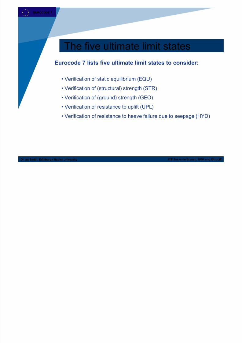
The five ultimate limit states
Eurocode 7 lists five ultimate limit states to consider:
• Verification of static equilibrium (EQU)
• Verification of (structural) strength (STR)• Verification of (ground) strength (GEO)
• Verification of resistance to uplift (UPL)
• Verification of resistance to heave failure due to seepage (HYD)

7/25/2019 Retaining Walls and Geotechnical Design to Eurocode 7 Summary
http://slidepdf.com/reader/full/retaining-walls-and-geotechnical-design-to-eurocode-7-summary 14/43
ICE Teesside Branch, NGG and IStructE
EUROCODE 7
Dr Ian Smith, Edinburgh Napier University
Ultimate limit states
Loss of static equilibrium
EQUEQU UPLUPLUplift by water pressure
HYDHYDHydraulic heave/erosion
GEOGEOFailure of the ground
STRSTRInternal failure of structure
ULS for Stability:ULS for Stability:
ULS for Strength:ULS for Strength:

7/25/2019 Retaining Walls and Geotechnical Design to Eurocode 7 Summary
http://slidepdf.com/reader/full/retaining-walls-and-geotechnical-design-to-eurocode-7-summary 15/43
ICE Teesside Branch, NGG and IStructE
EUROCODE 7
Dr Ian Smith, Edinburgh Napier University
Equilibrium (EQU) limit stateLoss of static equilibrium
Limit state is satisfied if the sum of the design values of the effects of destabilising actions
(Edst;d) is less than or equal to the sum of the design values of the effects of the stabilising
actions (Estb;d) together with any contribution through the resistance of the ground around
the structure (Td),
i.e. Edst;d ≤ Estb;d + Td.
EQU: loss of equilibrium of the structure or the
supporting ground when considered as a rigid body
and where the internal strength of the structure and
the ground do not provide resistance.

7/25/2019 Retaining Walls and Geotechnical Design to Eurocode 7 Summary
http://slidepdf.com/reader/full/retaining-walls-and-geotechnical-design-to-eurocode-7-summary 16/43
ICE Teesside Branch, NGG and IStructE
EUROCODE 7
Dr Ian Smith, Edinburgh Napier University
Geotechnical (GEO) limit stateFailure of the ground
This limit state is satisfied if the design effect of the actions (Ed) is less than or equal to the
design resistance (Rd),
i.e. Ed ≤ Rd
GEO: failure or excessive deformation of the ground,
where the soil or rock is significant in providing
resistance.

7/25/2019 Retaining Walls and Geotechnical Design to Eurocode 7 Summary
http://slidepdf.com/reader/full/retaining-walls-and-geotechnical-design-to-eurocode-7-summary 17/43
ICE Teesside Branch, NGG and IStructE
EUROCODE 7
Dr Ian Smith, Edinburgh Napier University
Structural (STR) limit stateInternal failure of structure
As with GEO limit state, the STR limit state is satisfied if the design effect of the actions (Ed)
is less than or equal to the design resistance (Rd),
i.e. Ed ≤ Rd
STR: failure or excessive deformation of the
structure, where the strength of the structural
material is significant in providing resistance.

7/25/2019 Retaining Walls and Geotechnical Design to Eurocode 7 Summary
http://slidepdf.com/reader/full/retaining-walls-and-geotechnical-design-to-eurocode-7-summary 18/43
ICE Teesside Branch, NGG and IStructE
EUROCODE 7
Dr Ian Smith, Edinburgh Napier University
Uplift (UPL) limit stateUplift by water pressure
This limit state is verified by checking that the sum of the design permanent and variable
destabilising vertical actions (Vdst;d) is less than or equal to the sum of the design stabilising
permanent vertical action (Gstb;d) and any additional resistance to uplift (Rd).
i.e. Vdst;d ≤ Gstb;d + Rd.
UPL: the loss of equilibrium of the structure or the
supporting ground by vertical uplift due to water
pressures (buoyancy) or other actions.
7/25/2019 Retaining Walls and Geotechnical Design to Eurocode 7 Summary
http://slidepdf.com/reader/full/retaining-walls-and-geotechnical-design-to-eurocode-7-summary 19/43
ICE Teesside Branch, NGG and IStructE
EUROCODE 7
Dr Ian Smith, Edinburgh Napier University
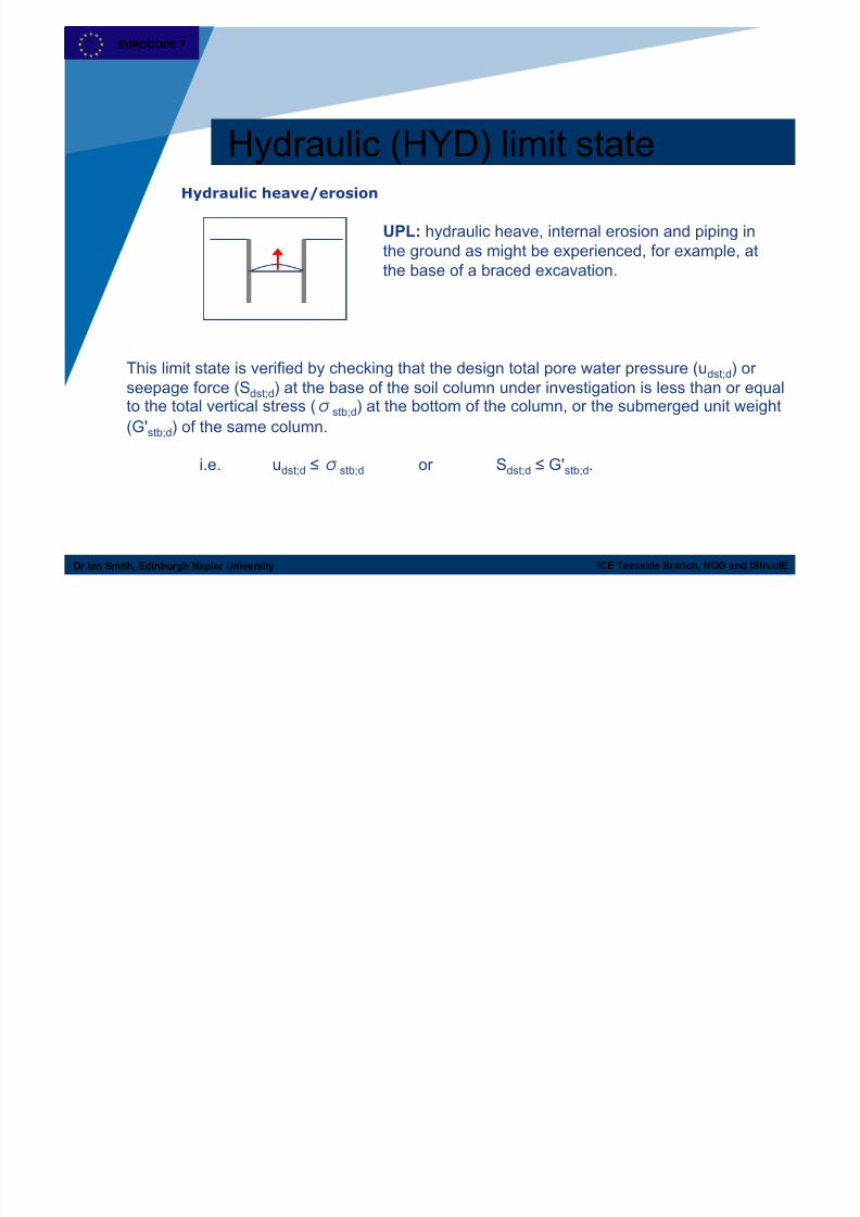
Hydraulic (HYD) limit stateHydraulic heave/erosion
This limit state is verified by checking that the design total pore water pressure (udst;d) or
seepage force (Sdst;d) at the base of the soil column under investigation is less than or equalto the total vertical stress (stb;d) at the bottom of the column, or the submerged unit weight
(G'stb;d) of the same column.
i.e. udst;d ≤stb;d or Sdst;d ≤ G'stb;d.
UPL: hydraulic heave, internal erosion and piping in
the ground as might be experienced, for example, at
the base of a braced excavation.

7/25/2019 Retaining Walls and Geotechnical Design to Eurocode 7 Summary
http://slidepdf.com/reader/full/retaining-walls-and-geotechnical-design-to-eurocode-7-summary 20/43
ICE Teesside Branch, NGG and IStructE
EUROCODE 7
Dr Ian Smith, Edinburgh Napier University
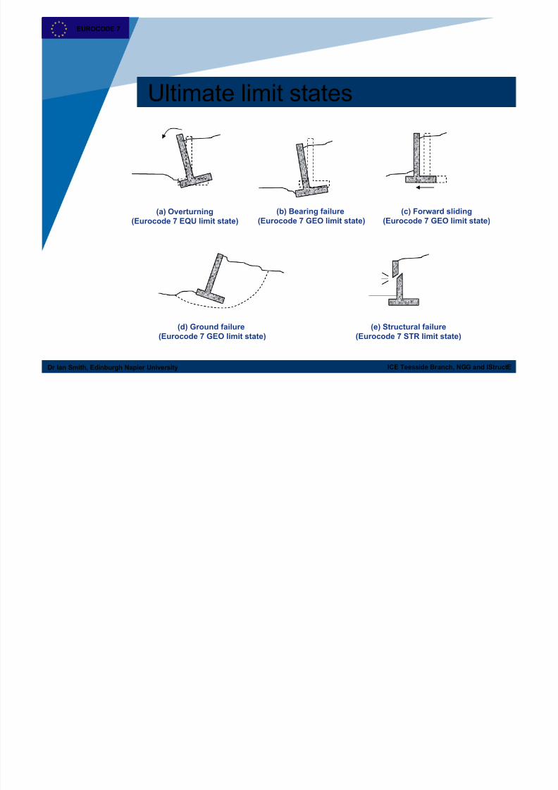
ULS for retaining structures
(a) Overturning(Eurocode 7 EQU limit state)
(b) Bearing failure(Eurocode 7 GEO limit state)
(c) Forward sliding(Eurocode 7 GEO limit state)
(d) Ground failure
(Eurocode 7 GEO limit state)
(e) Structural failure
(Eurocode 7 STR limit state)

7/25/2019 Retaining Walls and Geotechnical Design to Eurocode 7 Summary
http://slidepdf.com/reader/full/retaining-walls-and-geotechnical-design-to-eurocode-7-summary 21/43
ICE Teesside Branch, NGG and IStructE
EUROCODE 7
Dr Ian Smith, Edinburgh Napier University
EQU limit state
Destabilising actions and effects
Representative destabilising
actions, Fdst; rep
Partial factors,
F dst
GEOTECHNICAL ANALYSIS
Design effect of destabilising
actions, Edst;d
Representative stabilising
actions, Fstb; rep
Design effect of stabilising
actions, Estb;d
Verify Edst;d ≤ Estb;d
Stabilising actions and effects
Design destabilising
actions, Fdst;d
Design stabilising
actions, Fstb;d
Partial factors,
F stb

7/25/2019 Retaining Walls and Geotechnical Design to Eurocode 7 Summary
http://slidepdf.com/reader/full/retaining-walls-and-geotechnical-design-to-eurocode-7-summary 22/43
ICE Teesside Branch, NGG and IStructE
EUROCODE 7
Dr Ian Smith, Edinburgh Napier University
EQU limit state example
Pq
q
PaW
Overturning

7/25/2019 Retaining Walls and Geotechnical Design to Eurocode 7 Summary
http://slidepdf.com/reader/full/retaining-walls-and-geotechnical-design-to-eurocode-7-summary 23/43
ICE Teesside Branch, NGG and IStructE
EUROCODE 7
Dr Ian Smith, Edinburgh Napier University
GEO limit state
Actions and effects
Representative
actions, Frep
Partial factors, F
GEOTECHNICAL ANALYSIS
Design effect of actions,
Ed
Characteristic material
properties, Xk
Design resistance, Rd
Verify Ed ≤ Rd
Material properties and resistance
Design actions, Fd Design materialproperties, Xd
Partial factors, M

7/25/2019 Retaining Walls and Geotechnical Design to Eurocode 7 Summary
http://slidepdf.com/reader/full/retaining-walls-and-geotechnical-design-to-eurocode-7-summary 24/43
ICE Teesside Branch, NGG and IStructE
EUROCODE 7
Dr Ian Smith, Edinburgh Napier University
GEO/STR Limit states
Three Design Approaches are offered - to reflect national choice
The design approach followed reflects whether the safety is applied to the
material properties, the actions or the resistances.
Design Approach 1: Combination 1: A1 + M1 + R1†Combination 2: A2 + M2 + R1
Design Approach 2: A1 + M1 + R2Design Approach 3: A* + M2 + R3
A*: use set A1 on structural actions, set A2 on geotechnical actions
† For axially loaded piles, DA1, Combination 2 is: A2 + (M1 or M2) + R4
The UK National Annex states that Design Approach 1 shall be used.

7/25/2019 Retaining Walls and Geotechnical Design to Eurocode 7 Summary
http://slidepdf.com/reader/full/retaining-walls-and-geotechnical-design-to-eurocode-7-summary 25/43
ICE Teesside Branch, NGG and IStructE
EUROCODE 7
Dr Ian Smith, Edinburgh Napier University
GEO/STR Limit states
DA 1-1: A1 + M1 + R1 DA 1-2: A2 + M2 + R1DA 1-1: A1 + M1 + R1
GEO/STR - Partial factor sets
Parameter Symbol A1 A2 M1 M2 R1 R2 R3
Permanent action (G) Unfavourable G 1.35 1.0
Favourable G 1.0 1.0
Variable action (Q) Unfavourable Q 1.5 1.3
Favourable - - -
Accidental action (A) Unfavourable A 1.0 1.0
Favourable - - -
Coefficient of shearing resistance (tan ') ' 1.0 1.25
Effective cohesion (c') c' 1.0 1.25
Undrained shear strength (cu) cu 1.0 1.4
Unconfined compressive strength (qu)
qu1.0 1.4
Weight density () 1.0 1.0
Bearing resistance (Rv) Rv 1.0 1.4 1.0
Sliding resistance (Rh) Rh 1.0 1.1 1.0
Earth resistance (Re) Re 1.0 1.4 1.0

7/25/2019 Retaining Walls and Geotechnical Design to Eurocode 7 Summary
http://slidepdf.com/reader/full/retaining-walls-and-geotechnical-design-to-eurocode-7-summary 26/43
ICE Teesside Branch, NGG and IStructE
EUROCODE 7
Dr Ian Smith, Edinburgh Napier University
Representation of degree of safety
Over-design factor:
Degree of utilisation:
d
d
E
R
d
d
R
E
7/25/2019 Retaining Walls and Geotechnical Design to Eurocode 7 Summary
http://slidepdf.com/reader/full/retaining-walls-and-geotechnical-design-to-eurocode-7-summary 27/43
ICE Teesside Branch, NGG and IStructE
EUROCODE 7
Dr Ian Smith, Edinburgh Napier University
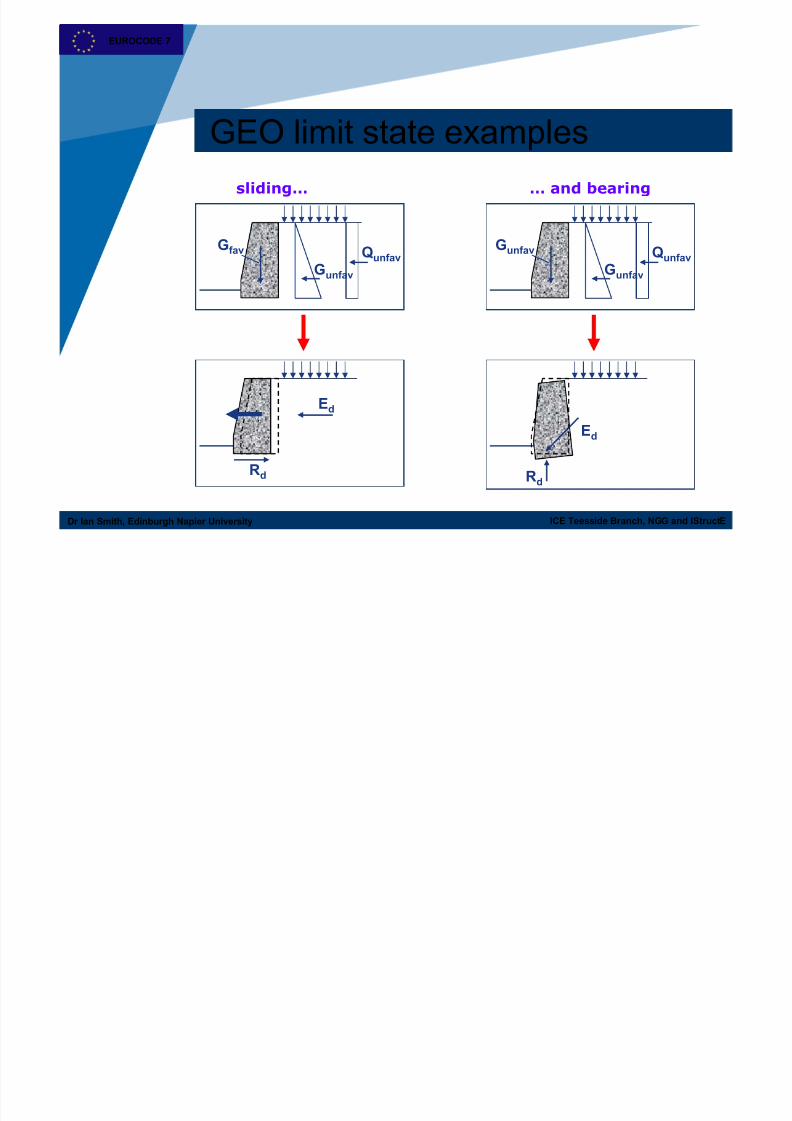
Gfav
Gunfav
Qunfav
Ed
Rd
Gunfav
Gunfav
Qunfav
Ed
Rd
sliding… … and bearing
GEO limit state examples
7/25/2019 Retaining Walls and Geotechnical Design to Eurocode 7 Summary
http://slidepdf.com/reader/full/retaining-walls-and-geotechnical-design-to-eurocode-7-summary 28/43
ICE Teesside Branch, NGG and IStructE
EUROCODE 7
Dr Ian Smith, Edinburgh Napier University
Retaining wall design
(1)P The provisions of this Section shall apply to structures, which retain
ground comprising soil, rock or backfill and water. Material is retained if it
is kept at a slope steeper than it would eventually adopt if no structure
were present.
Retaining structures include all types of wall and support systems in
which structural elements have forces imposed by the retained material.
EN 1997-1:2004 9.1.1(1)P
Covered in Section 9 of Eurocode 7 Part 1
EUROCODE 7

7/25/2019 Retaining Walls and Geotechnical Design to Eurocode 7 Summary
http://slidepdf.com/reader/full/retaining-walls-and-geotechnical-design-to-eurocode-7-summary 29/43
ICE Teesside Branch, NGG and IStructE
EUROCODE 7
Dr Ian Smith, Edinburgh Napier University
Retaining wall design
The limit states to be considered are listed in9.2(1) and are:
• loss of overall stability;
• failure of a structural element such as a wall, anchorage, wale or strut
or failure of the connection between such elements;• combined failure in the ground and in the structural element;
• failure by hydraulic heave and piping;
• movement of the retaining structure, which may cause collapse or
affect the appearance or
• efficient use of the structure or nearby structures or services, which rely
on it;
• unacceptable leakage through or beneath the wall;
• unacceptable transport of soil particles through or beneath the wall;
• unacceptable change in the ground-water regime.
EN 1997-1:2004 9.2(1)
Limit states
EUROCODE 7

7/25/2019 Retaining Walls and Geotechnical Design to Eurocode 7 Summary
http://slidepdf.com/reader/full/retaining-walls-and-geotechnical-design-to-eurocode-7-summary 30/43
ICE Teesside Branch, NGG and IStructE
EUROCODE 7
Dr Ian Smith, Edinburgh Napier University
Retaining wall design
Gravity walls:
bearing resistance failure of the soil below the base;
failure by sliding at the base;
failure by toppling;
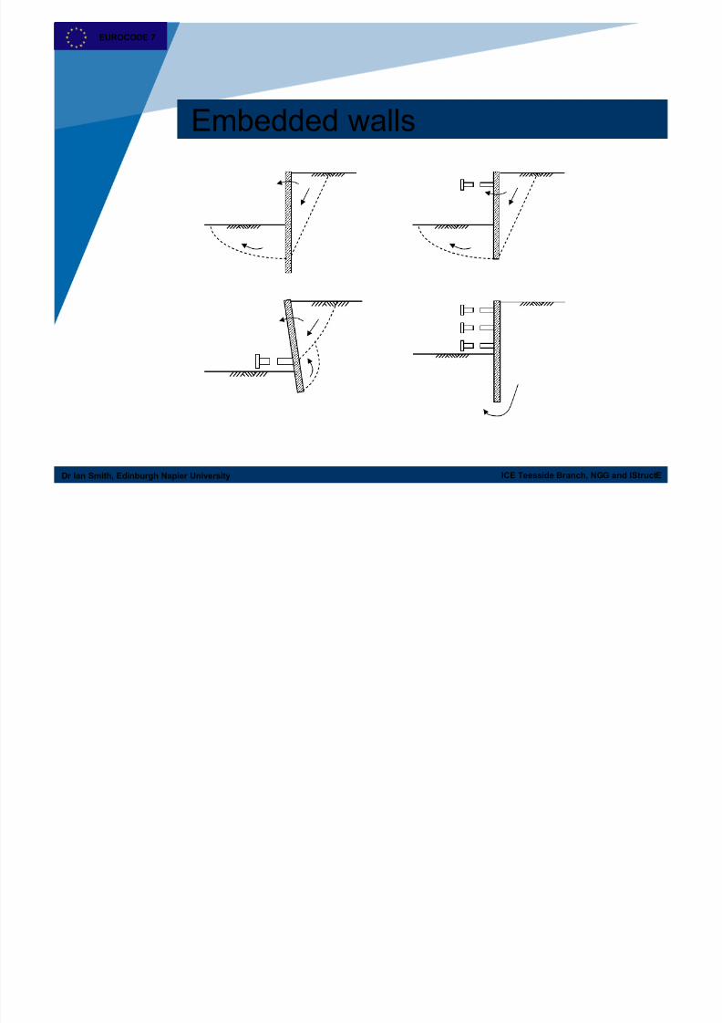
Embedded walls:
failure by rotation or translation of the wall or parts thereof;
failure by lack of vertical equilibrium.
EN 1997-1:2004 9.2(1)
Plus…
EUROCODE 7
7/25/2019 Retaining Walls and Geotechnical Design to Eurocode 7 Summary
http://slidepdf.com/reader/full/retaining-walls-and-geotechnical-design-to-eurocode-7-summary 31/43
ICE Teesside Branch, NGG and IStructE
EUROCODE 7
Dr Ian Smith, Edinburgh Napier University
Ultimate limit states
(a) Overturning(Eurocode 7 EQU limit state)
(b) Bearing failure(Eurocode 7 GEO limit state)
(c) Forward sliding(Eurocode 7 GEO limit state)
(d) Ground failure
(Eurocode 7 GEO limit state)
(e) Structural failure
(Eurocode 7 STR limit state)
EUROCODE 7

7/25/2019 Retaining Walls and Geotechnical Design to Eurocode 7 Summary
http://slidepdf.com/reader/full/retaining-walls-and-geotechnical-design-to-eurocode-7-summary 32/43
ICE Teesside Branch, NGG and IStructE
EUROCODE 7
Dr Ian Smith, Edinburgh Napier University
Ultimate limit states
Must also consider overall stability (Section 11)…
EUROCODE 7
7/25/2019 Retaining Walls and Geotechnical Design to Eurocode 7 Summary
http://slidepdf.com/reader/full/retaining-walls-and-geotechnical-design-to-eurocode-7-summary 33/43
ICE Teesside Branch, NGG and IStructE
EUROCODE 7
Dr Ian Smith, Edinburgh Napier University
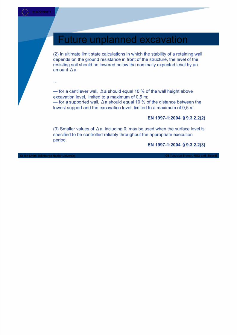
Future unplanned excavation
(2) In ultimate limit state calculations in which the stability of a retaining wall
depends on the ground resistance in front of the structure, the level of theresisting soil should be lowered below the nominally expected level by anamounta.
…
— for a cantilever wall,a should equal 10 % of the wall height above
excavation level, limited to a maximum of 0,5 m;— for a supported wall,a should equal 10 % of the distance between the
lowest support and the excavation level, limited to a maximum of 0,5 m.
EN 1997-1:2004 9.3.2.2(2)
(3) Smaller values ofa, including 0, may be used when the surface level is
specified to be controlled reliably throughout the appropriate execution
period.EN 1997-1:2004 9.3.2.2(3)
EUROCODE 7
7/25/2019 Retaining Walls and Geotechnical Design to Eurocode 7 Summary
http://slidepdf.com/reader/full/retaining-walls-and-geotechnical-design-to-eurocode-7-summary 34/43
ICE Teesside Branch, NGG and IStructEDr Ian Smith, Edinburgh Napier University
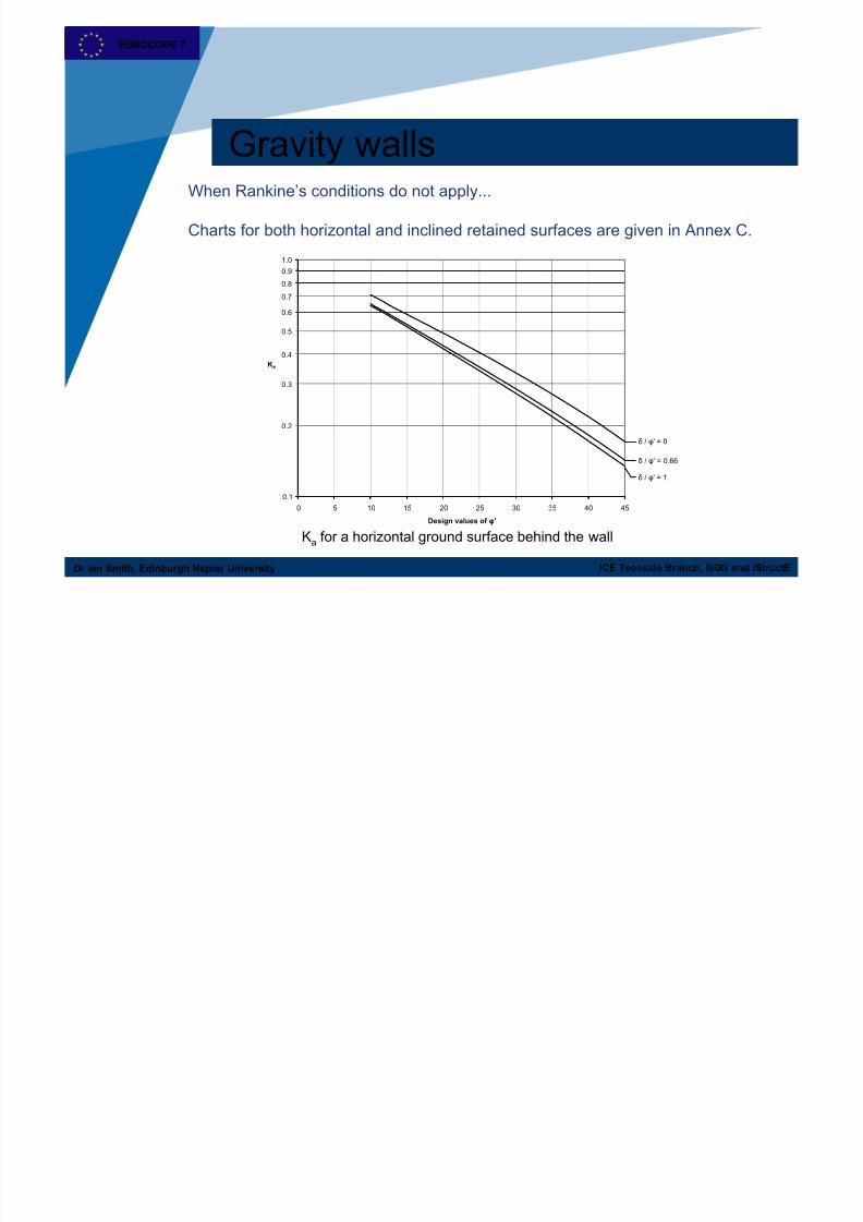
Gravity wallsWhen Rankine’s conditions do not apply...
Charts for both horizontal and inclined retained surfaces are given in Annex C.
Ka for a horizontal ground surface behind the wall
0.1
1
0 5 10 15 20 25 30 35 40 45
Design values of φ'
Ka
0.2
0.3
0.4
0.5
0.6
0.7
0.8
0.9
δ / φ' = 0
δ / φ' = 0.66
δ / φ' = 1
1.0
EUROCODE 7

7/25/2019 Retaining Walls and Geotechnical Design to Eurocode 7 Summary
http://slidepdf.com/reader/full/retaining-walls-and-geotechnical-design-to-eurocode-7-summary 35/43
ICE Teesside Branch, NGG and IStructEDr Ian Smith, Edinburgh Napier University
Example
Retained fill:
c' = 0; ' = 32
= 18 kN/m34.0 m
2.0 m
2.6 m
1.8 m
1.0 m Foundation soil:
c' = 0; ' = 28
= 20 kN/m3
Surcharge, q = 20 kPa
3
1
2
= 22.4 kPa
= 26.7 kPa
34.1 kPa
= 6.2 kPa
7.4 kPa
haK qaK
Check the overturning (EQU) and sliding (GEO) (using Design Approach 1) limit states.
EUROCODE 7
7/25/2019 Retaining Walls and Geotechnical Design to Eurocode 7 Summary
http://slidepdf.com/reader/full/retaining-walls-and-geotechnical-design-to-eurocode-7-summary 36/43
ICE Teesside Branch, NGG and IStructEDr Ian Smith, Edinburgh Napier University
Embedded walls
EUROCODE 7

7/25/2019 Retaining Walls and Geotechnical Design to Eurocode 7 Summary
http://slidepdf.com/reader/full/retaining-walls-and-geotechnical-design-to-eurocode-7-summary 37/43
ICE Teesside Branch, NGG and IStructEDr Ian Smith, Edinburgh Napier University
Embedded walls
d K pd 0
O K a(h+d 0)
q = 10kPa
K p(h+d)
K ad
d 0
h0.1h; > 0.5m
Pq1
Pq2
Pa1
Pp2
Pp1
Pa2
Cantilever wall – pressure distribution
EUROCODE 7
7/25/2019 Retaining Walls and Geotechnical Design to Eurocode 7 Summary
http://slidepdf.com/reader/full/retaining-walls-and-geotechnical-design-to-eurocode-7-summary 38/43
ICE Teesside Branch, NGG and IStructEDr Ian Smith, Edinburgh Napier University
Embedded walls
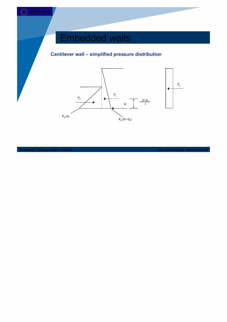
Cantilever wall – simplified pressure distribution
K a(h+d 0)
P p
Pa
R
K pd 0
h+d 03
Pq
EUROCODE 7

7/25/2019 Retaining Walls and Geotechnical Design to Eurocode 7 Summary
http://slidepdf.com/reader/full/retaining-walls-and-geotechnical-design-to-eurocode-7-summary 39/43
ICE Teesside Branch, NGG and IStructEDr Ian Smith, Edinburgh Napier University
Passive resistance
favGk pd p PP ;;;
Re
;
;
k p
d p
P
P
Favourable action:
or
Resistance:
EUROCODE 7

7/25/2019 Retaining Walls and Geotechnical Design to Eurocode 7 Summary
http://slidepdf.com/reader/full/retaining-walls-and-geotechnical-design-to-eurocode-7-summary 40/43
ICE Teesside Branch, NGG and IStructEDr Ian Smith, Edinburgh Napier University
Passive resistance
Design Approach
1 2 3
Combination 1 Combination 2
G;fav1.0 1.0 1.0 1.0
Re1.0 1.0 1.4 1.0
i.e. only concerns Design Approach 2
EUROCODE 7

7/25/2019 Retaining Walls and Geotechnical Design to Eurocode 7 Summary
http://slidepdf.com/reader/full/retaining-walls-and-geotechnical-design-to-eurocode-7-summary 41/43
ICE Teesside Branch, NGG and IStructEDr Ian Smith, Edinburgh Napier University
Passive resistance
but what about for embedded walls?…
Single Source Principle…
NOTE Unfavourable (or destabilising) and favourable (or stabilising)permanent actions may in some situations be considered as coming from a
single source. If they are considered so, a single partial factor may be
applied to the sum of these actions or to the sum of their effects.
EN 1997-1:2004 2.4.2Note to (9)P
EUROCODE 7

7/25/2019 Retaining Walls and Geotechnical Design to Eurocode 7 Summary
http://slidepdf.com/reader/full/retaining-walls-and-geotechnical-design-to-eurocode-7-summary 42/43
ICE Teesside Branch, NGG and IStructEDr Ian Smith, Edinburgh Napier University
Passive resistance
P p
Pa
“uncertainty” in Pp = “uncertainty” in Pa
i.e. if Pa is a permanent unfavourable action, so must be Pp
(Single source principle)
EUROCODE 7

7/25/2019 Retaining Walls and Geotechnical Design to Eurocode 7 Summary
http://slidepdf.com/reader/full/retaining-walls-and-geotechnical-design-to-eurocode-7-summary 43/43
ICE Teesside Branch, NGG and IStructEDr Ian Smith, Edinburgh Napier University
Passive resistance
Design Approach
1 2 3
Combination
1
Combination
2
G;fav1.0 1.0 1.0 1.0
G;unfav1.35 1.0 1.35 1.0
Re1.0 1.0 1.4 1.0