retpo001 ct en
TRANSCRIPT

8/2/2019 Retpo001 Ct En
http://slidepdf.com/reader/full/retpo001-ct-en 1/16
41
POSI LOCK POSI LOCK
The permissible tolerances of size for the shaft and the
mounting part are large. Besides, any special finish is
not required. Phase alignment and positioning can be
easily done. There is no backlash.
■ PSL-K model
■ PSL-G model
■ PSL-D model
Max. permissible torque [N・m] 4.7∼2810
Max. permissible thrust power[N] 1560∼93600
Bore diameter [mm] φ6∼60
Operating temp. limit [℃]
Backlash
−40∼+150
Zero■ Principle of Operation
・ By tightening the clamping bolt, the outer sleeve moves to the axial direction. At thistime, a force that pushes the inside shaft andhub is generated by the wedge action on thetaper surface of the inner sleeve. The shaftand hub are completely fastened by the push-ing force. The wedge effect is enhanced bythe groove of the inner sleeve that hightransfer torque can be obtained.
■ PSL-K
Clamping boltInner sleeve
Groove
Outer sleeve
Detaching screw hole
・ By fastening the clamping bolt, two taper rings move to the axial direction. At this time, aforce that pushes the inside shaft and hub isgenerated by the wedge action on each taper surface of the outer and inner rings. The shaftand hub are completely fastened by the push-ing force.
■ PSL-G
Outer ring
Rear taper ring
Front taper ring
Clamping bolt
Detachingscrew hole
Inner ring
・ By fastening the clamping bolt, the outer ringmoves to the axial direction. At this time, aforce that pushes the inside shaft and hub isgenerated by the wedge action on the taper surface of the inner ring. The shaft and hubare completely fastened by the pushing force.
■ PSL-D
Outer ring
Clamping bolt
Detaching screw hole
Inner ring
P OS I L OC K
■ Adapted to the RoHSAdapted to the Restriction of Hazardous Substances
defined by EU that bans the use of 6 substances such asmercury or lead.
* As of June 2006

8/2/2019 Retpo001 Ct En
http://slidepdf.com/reader/full/retpo001-ct-en 2/16
Outer sleeve material:equivalent of S45C thermal refining
Inner sleeve material:equivalent of S45C thermal refining
Clamping bolt material: SCM435Surface treatment: Black oxide finish
Outer sleeve material:
equivalent of S45C thermal refiningInner sleeve material:equivalent of S45C thermal refining
Clamping bolt material: SCM435Surface treatment: Black oxide finish
42
■ Model List
Model Body materialAppropriate shaft dia.
[mm]Max. permissible torque
[N・m]Max. permissible thrust
power[N]
PSL-K S45C Thermal Refining or similar 6∼40 5.9∼720 1950∼36000
PSL-K-B S45C Thermal Refining or similar 6∼40 5.9∼720 1950∼36000
PSL-K-C S45C T.R. or similar (electroless nickel plate) 6∼40 5.9∼720 1950∼36000
PSL-K-F SUS304 Thermal Refining or similar 6∼35 4.7∼504 1560∼28800
PSL-G S45C Thermal Refining or similar 19∼60 289∼2810 30500∼93600
PSL-G-C S45C T.R. or similar (electroless nickel plate) 19∼60 289∼2810 30500∼93600
PSL-D S45C Thermal Refining or similar 6∼50 6∼1760 2100∼70300
PSL-D-C S45C T.R. or similar (electroless nickel plate) 16∼50 67∼1760 8400∼70300
PSL-K model
■ Structure and Material
■ PSL-KBecause the outside-diameter ratio of the inside sleeve
is small, the diameter of mounting parts and the
moment of inertia can be reduced. Its mechanism issimple, and high-accuracy concentricity can be
retained.
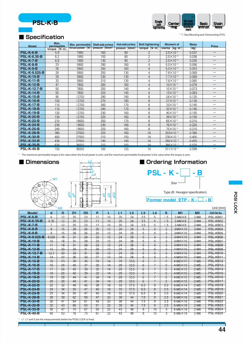
■ PSL-K-B (Hexagon bolt specification)Hexagon bolt is used for the clamping bolt. ThePSL-K-B can be assembled if there is not enoughspace in the thrust direction.
Outer sleeve material:equivalent of S45C thermal refiningSurface treatment: Electroless nickel plating
Inner sleeve material:
equivalent of S45C thermal refiningSurface treatment: Electroless nickel plating
Clamping bolt material: SCM435Surface treatment: Dcrotized treatment
Outer sleeve material: SUS304
Inner sleeve material: SUS304
Clamping bolt material: SUH660Surface treatment: Defric coating
■ PSL-K-C (Basic antirust specification)A basic antirust specification with electrolessnickel plating coated on the body.
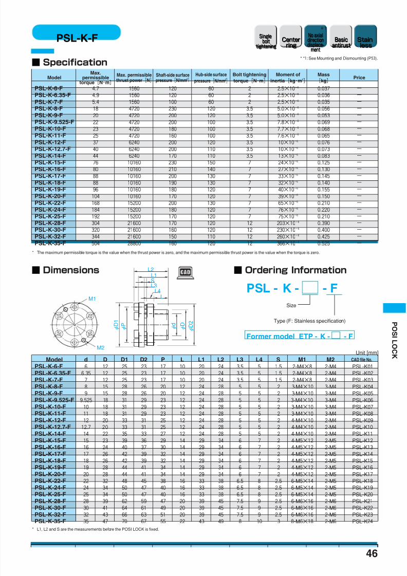
■ PSL-K-F (Stainless specification)Basic antirust specification with stainless materialused on the body.
Outer ring material:Equivalent of S45C thermal refiningInner ring material:Equivalent of S45C thermal refiningFront taper ring material:Equivalent of S45C thermal refining
Rear taper ring material:Equivalent of S45C thermal refiningClamping bolt material: SCM435Surface treatment: Black oxide finish
Outer ring material:Equivalent of S45C thermal refiningSurface treatment: Electroless nickel plating
Inner ring material:Equivalent of S45C thermal refiningSurface treatment: Electroless nickel plating
Front taper ring material:Equivalent of S45C thermal refiningSurface treatment: Electroless nickel platingRear taper ring material:Equivalent of S45C thermal refiningSurface treatment: Electroless nickel platingClamping bolt material: SCM45Surface treatment: Dcrotized treatment
PSL-G model
■ PSL-GHomogeneous transmission abi l ity can beobtained by the simple structure and strongcomponent. The PSL-G also corresponds to heavyloading. It is shorter to the axial direction thatspace can be saved.
■ PSL-G-C (Basic antirust specification)A basic antirust specification with electrolessnickel plating coated on the body.
Outer sleeve material:equivalent of S45C thermal refining
Inner sleeve material:equivalent of S45C thermal refining
Clamping bolt material: SCM435Surface treatment: Dcrotized treatment
Black oxide finish (Size 6 to 15)
Outer ring material:Equivalent of S45C thermal refiningSurface treatment: Electroless nickel plating
Inner ring material:Equivalent of S45C thermal refiningSurface treatment: Electroless nickel plating
Clamping bolt material: SCM435Surface treatment: Dcrotized treatment
PSL-D model
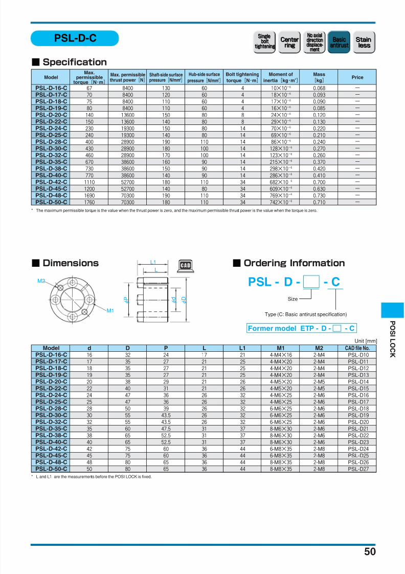
■PSL-DThe PSL-D is designed for middle loading. Because itssurface pressure is low, reduction in size and weightcan be performed. It is shorter to the axial directionthat space can be saved.
■ PSL-D-C (Basic antirust specification)A basic antirust specification with electrolessnickel plating coated on the body.
* Special coating is used for the clamping bolt to stabilize the axial force.P O S I L O C K

8/2/2019 Retpo001 Ct En
http://slidepdf.com/reader/full/retpo001-ct-en 3/16
43
P OS I L OC K
M1
M2
φ D 1
φ P
φ d
φ D
φ D 2
L3SL1
L2
LL4
■ Specification
■ Dimensions
* L1, L2 and S are the measurements before the POSI LOCK is fixed.
* The maximum permissible torque is the value when the thrust power is zero, and the maximum permissible thrust power is the value when the torque is zero.
PSL-K
Unit [mm]
Model
PSL-K-6 5.9 1950 160 80 2 2.5×10⁻⁶
0.037 −PSL-K-6.35 6.2 1950 150 80 2 2.5×10
−60.036 −
PSL-K-7 6.8 1950 130 80 2 2.5×10⁻⁶ 0.035 −PSL-K-8 23 5900 290 160 4 5.0×10
−60.056 −
PSL-K-9 26 5900 260 160 4 5.0×10⁻⁶
0.053 −PSL-K-9.525 28 5900 250 130 4 7.8×10
−60.069 −
PSL-K-10 29 5900 230 130 4 7.7×10⁻⁶
0.068 −PSL-K-11 32 5900 210 130 4 7.6×10
−60.065 −
PSL-K-12 47 7800 260 160 4 10×10−6
0.076 −PSL-K-12.7 50 7800 250 140 4 10×10
−60.073 −
PSL-K-14 55 7800 220 140 4 13×10−6
0.083 −PSL-K-15 95 12700 290 190 8 24×10
−60.125 −
PSL-K-16 100 12700 270 180 8 27×10−6
0.130 −PSL-K-17 110 12700 260 170 8 33×10
−60.145 −
PSL-K-18 110 12700 240 170 8 32×10−6
0.140 −PSL-K-19 120 12700 230 160 8 40×10
−60.155 −
PSL-K-20 130 12700 220 160 8 39×10−6
0.150 −
PSL-K-22 210 19000 250 170 8 65×10−6 0.210 −PSL-K-24 230 19000 230 160 8 76×10
−60.220 −
PSL-K-25 240 19000 220 160 8 75×10−6
0.210 −PSL-K-28 380 27000 220 160 14 203×10
−60.390 −
PSL-K-30 400 27000 210 150 14 230×10−6
0.400 −PSL-K-32 430 27000 190 140 14 260×10
−60.425 −
PSL-K-35 630 36000 210 150 14 366×10−6
0.525 −PSL-K-40 720 36000 160 120 14 511×10
−60.599 −
Max.permissible
torque[N・m]
Max. permissiblethrust power[N]
Shaft-side surfacepressure[N/mm2]
Hub-side surfacepressure[N/mm2]
Bolt tighteningtorque[N・m]
Moment ofinertia[kg・m2]
Mass[kg]
Price
Model d D D1 D2 P L L1 L2 L3 L4 S M1 M2 CAD file No.
PSL-K-6 6 12 25 23 17 10 20 24 3.5 5 1.5 2-M4×8 2-M4 PSL-K01
PSL-K-6.35 6.35 12 25 23 17 10 20 24 3.5 5 1.5 2-M4×8 2-M4 PSL-K02
PSL-K-7 7 12 25 23 17 10 20 24 3.5 5 1.5 2-M4×8 2-M4 PSL-K03
PSL-K-8 8 15 28 26 20 12 24 28 5 5 2 3-M4×10 3-M4 PSL-K04
PSL-K-9 9 15 28 26 20 12 24 28 5 5 2 3-M4×10 3-M4 PSL-K05
PSL-K-9.525 9.525 18 31 29 23 12 24 28 5 5 2 3-M4×10 3-M4 PSL-K06
PSL-K-10 10 18 31 29 23 12 24 28 5 5 2 3-M4×10 3-M4 PSL-K07
PSL-K-11 11 18 31 29 23 12 24 28 5 5 2 3-M4×10 3-M4 PSL-K08
PSL-K-12 12 20 33 31 25 12 24 28 5 5 2 4-M4×10 2-M4 PSL-K09
PSL-K-12.7 12.7 20 33 31 25 12 24 28 5 5 2 4-M4×10 2-M4 PSL-K10
PSL-K-14 14 22 35 33 27 12 24 28 5 5 2 4-M4×10 2-M4 PSL-K11
PSL-K-15 15 23 39 36 29 14 29 34 6 7 2 4-M5×12 2-M5 PSL-K12
PSL-K-16 16 24 40 37 30 14 29 34 6 7 2 4-M5×12 2-M5 PSL-K13
PSL-K-17 17 26 42 39 32 14 29 34 6 7 2 4-M5×12 2-M5 PSL-K14
PSL-K-18 18 26 42 39 32 14 29 34 6 7 2 4-M5×12 2-M5 PSL-K15
PSL-K-19 19 28 44 41 34 14 29 34 6 7 2 4-M5×12 2-M5 PSL-K16
PSL-K-20 20 28 44 41 34 14 29 34 6 7 2 4-M5×12 2-M5 PSL-K17
PSL-K-22 22 32 48 45 38 16 33 38 6.5 8 2.5 6-M5×14 2-M5 PSL-K18
PSL-K-24 24 34 50 47 40 16 33 38 6.5 8 2.5 6-M5×14 2-M5 PSL-K19
PSL-K-25 25 34 50 47 40 16 33 38 6.5 8 2.5 6-M5×14 2-M5 PSL-K20
PSL-K-28 28 39 62 59 47 20 39 45 7.5 9 2.5 6-M6×16 2-M6 PSL-K21
PSL-K-30 30 41 64 61 49 20 39 45 7.5 9 2.5 6-M6×16 2-M6 PSL-K22
PSL-K-32 32 43 66 63 51 20 39 45 7.5 9 2.5 6-M6×16 2-M6 PSL-K23
PSL-K-35 35 47 70 67 55 22 43 49 8 10 3 8-M6×18 2-M6 PSL-K24
PSL-K-40 40 53 76 73 61 22 43 49 8 10 3 8-M6×18 2-M6 PSL-K25
PSL - K -
Former model ETP - K -
Size
■ Ordering Information
Stainless
Stainless
Basicantirust
Basic
antirust
No axialdirectiondisplace-
ment
No axialdirectiondisplace-
ment
Centerring
Centerring
Singlebolt
tightening
Singlebolt
tightening
*1
* *1: See Mounting and Dismounting (P53).
8/2/2019 Retpo001 Ct En
http://slidepdf.com/reader/full/retpo001-ct-en 4/16
44
P O S I L O C K
M1
M2
φ D 1
φ P
φ d
φ D
φ D 2
L3SL1
L2
LL4
■ Specification
■ Dimensions
* L1, L2 and S are the measurements before the POSI LOCK is fixed.
* The maximum permissible torque is the value when the thrust power is zero, and the maximum permissible thrust power is the value when the torque is zero.
PSL-K-B
Unit [mm]
Model
PSL-K-6-B 5.9 1950 160 80 2 2.5×10⁻⁶
0.037 −PSL-K-6.35-B 6.2 1950 150 80 2 2.5×10
−60.036 −
PSL-K-7-B 6.8 1950 130 80 2 2.5×10⁻⁶ 0.035 −PSL-K-8-B 23 5900 290 160 4 5.0×10
−60.056 −
PSL-K-9-B 26 5900 260 160 4 5.0×10⁻⁶
0.053 −PSL-K-9.525-B 28 5900 250 130 4 7.8×10
−60.069 −
PSL-K-10-B 29 5900 230 130 4 7.7×10⁻⁶
0.068 −PSL-K-11-B 32 5900 210 130 4 7.6×10
−60.065 −
PSL-K-12-B 47 7800 260 160 4 10×10−6
0.076 −PSL-K-12.7-B 50 7800 250 140 4 10×10
−60.073 −
PSL-K-14-B 55 7800 220 140 4 13×10−6
0.083 −PSL-K-15-B 95 12700 290 190 8 24×10
−60.125 −
PSL-K-16-B 100 12700 270 180 8 27×10−6
0.130 −PSL-K-17-B 110 12700 260 170 8 33×10
−60.145 −
PSL-K-18-B 110 12700 240 170 8 32×10−6
0.140 −PSL-K-19-B 120 12700 230 160 8 40×10
−60.155 −
PSL-K-20-B 130 12700 220 160 8 39×10−6
0.150 −
PSL-K-22-B 210 19000 250 170 8 65×10−6 0.210 −PSL-K-24-B 230 19000 230 160 8 76×10
−60.220 −
PSL-K-25-B 240 19000 220 160 8 75×10−6
0.210 −PSL-K-28-B 380 27000 220 160 14 203×10
−60.390 −
PSL-K-30-B 400 27000 210 150 14 230×10−6
0.400 −PSL-K-32-B 430 27000 190 140 14 260×10
−60.425 −
PSL-K-35-B 630 36000 210 150 14 366×10−6
0.525 −PSL-K-40-B 720 36000 160 120 14 511×10
−60.599 −
Max.permissible
torque[N・m]
Max. permissiblethrust power[N]
Shaft-side surfacepressure[N/mm2]
Hub-side surfacepressure[N/mm2]
Bolt tighteningtorque[N・m]
Moment ofinertia[kg・m2]
Mass[kg]
Price
Stainless
Stainless
Basicantirust
Basic
antirust
No axialdirectiondisplace-
ment
No axialdirectiondisplace-
ment
Centerring
Centerring
Singlebolt
tightening
Singlebolt
tightening
PSL - K - - B
Former model ETP - K - - B
Type (B: Hexagon specification)
Size
■ Ordering Information
d D D1 D2 P L L1 L2 L3 L4 S M1 M2 CAD file No.
PSL-K-6-B 6 12 25 23 17 10 20 24 3.5 5 1.5 2-M4×8 2-M4 PSL-KB01
PSL-K-6.35-B 6.35 12 25 23 17 10 20 24 3.5 5 1.5 2-M4×8 2-M4 PSL-KB02
PSL-K-7-B 7 12 25 23 17 10 20 24 3.5 5 1.5 2-M4×8 2-M4 PSL-KB03
PSL-K-8-B 8 15 28 26 20 12 24 28 5 5 2 3-M4×10 3-M4 PSL-KB04
PSL-K-9-B 9 15 28 26 20 12 24 28 5 5 2 3-M4×10 3-M4 PSL-KB05
PSL-K-9.525-B 9.525 18 31 29 23 12 24 28 5 5 2 3-M4×10 3-M4 PSL-KB06
PSL-K-10-B 10 18 31 29 23 12 24 28 5 5 2 3-M4×10 3-M4 PSL-KB07
PSL-K-11-B 11 18 31 29 23 12 24 28 5 5 2 3-M4×10 3-M4 PSL-KB08
PSL-K-12-B 12 20 33 31 25 12 24 28 5 5 2 4-M4×10 2-M4 PSL-KB09
PSL-K-12.7-B 12.7 20 33 31 25 12 24 28 5 5 2 4-M4×10 2-M4 PSL-KB10PSL-K-14-B 14 22 35 33 27 12 24 28 5 5 2 4-M4×10 2-M4 PSL-KB11PSL-K-15-B 15 23 39 36 29 14 29 33.5 6 7 2 4-M5×12 2-M5 PSL-KB12PSL-K-16-B 16 24 40 37 30 14 29 33.5 6 7 2 4-M5×12 2-M5 PSL-KB13PSL-K-17-B 17 26 42 39 32 14 29 33.5 6 7 2 4-M5×12 2-M5 PSL-KB14PSL-K-18-B 18 26 42 39 32 14 29 33.5 6 7 2 4-M5×12 2-M5 PSL-KB15PSL-K-19-B 19 28 44 41 34 14 29 33.5 6 7 2 4-M5×12 2-M5 PSL-KB16PSL-K-20-B 20 28 44 41 34 14 29 33.5 6 7 2 4-M5×12 2-M5 PSL-KB17PSL-K-22-B 22 32 48 45 38 16 33 37.5 6.5 8 2.5 6-M5×14 2-M5 PSL-KB18PSL-K-24-B 24 34 50 47 40 16 33 37.5 6.5 8 2.5 6-M5×14 2-M5 PSL-KB19PSL-K-25-B 25 34 50 47 40 16 33 37.5 6.5 8 2.5 6-M5×14 2-M5 PSL-KB20PSL-K-28-B 28 39 62 59 47 20 39 44 7.5 9 2.5 6-M6×16 2-M6 PSL-KB21
PSL-K-30-B 30 41 64 61 49 20 39 44 7.5 9 2.5 6-M6×16 2-M6 PSL-KB22PSL-K-32-B 32 43 66 63 51 20 39 44 7.5 9 2.5 6-M6×16 2-M6 PSL-KB23PSL-K-35-B 35 47 70 67 55 22 43 48 8 10 3 8-M6×18 2-M6 PSL-KB24PSL-K-40-B 40 53 76 73 61 22 43 48 8 10 3 8-M6×18 2-M6 PSL-KB25
Model
*1
* *1: See Mounting and Dismounting (P53).

8/2/2019 Retpo001 Ct En
http://slidepdf.com/reader/full/retpo001-ct-en 5/16
45
P OS I L OC K
M1
M2
φ D 1
φ P
φ d
φ D
φ D 2
L3SL1
L2
LL4
■ Specification
■ Dimensions
* L1, L2 and S are the measurements before the POSI LOCK is fixed.
* The maximum permissible torque is the value when the thrust power is zero, and the maximum permissible thrust power is the value when the torque is zero.
PSL-K-C
Unit [mm]
Model
PSL-K-6-C 5.9 1950 160 80 2 2.5×10⁻⁶
0.037 −PSL-K-6.35-C 6.2 1950 150 80 2 2.5×10
−60.036 −
PSL-K-7-C 6.8 1950 130 80 2 2.5×10⁻⁶ 0.035 −PSL-K-8-C 23 5900 290 160 4 5.0×10
−60.056 −
PSL-K-9-C 26 5900 260 160 4 5.0×10⁻⁶
0.053 −PSL-K-9.525-C 28 5900 250 130 4 7.8×10
−60.069 −
PSL-K-10-C 29 5900 230 130 4 7.7×10⁻⁶
0.068 −PSL-K-11-C 32 5900 210 130 4 7.6×10
−60.065 −
PSL-K-12-C 47 7800 260 160 4 10×10−6
0.076 −PSL-K-12.7-C 50 7800 250 140 4 10×10
−60.073 −
PSL-K-14-C 55 7800 220 140 4 13×10−6
0.083 −PSL-K-15-C 95 12700 290 190 8 24×10
−60.125 −
PSL-K-16-C 100 12700 270 180 8 27×10−6
0.130 −PSL-K-17-C 110 12700 260 170 8 33×10
−60.145 −
PSL-K-18-C 110 12700 240 170 8 32×10−6
0.140 −PSL-K-19-C 120 12700 230 160 8 40×10
−60.155 −
PSL-K-20-C 130 12700 220 160 8 39×10−6
0.150 −
PSL-K-22-C 210 19000 250 170 8 65×10−6 0.210 −PSL-K-24-C 230 19000 230 160 8 76×10
−60.220 −
PSL-K-25-C 240 19000 220 160 8 75×10−6
0.210 −PSL-K-28-C 380 27000 220 160 14 203×10
−60.390 −
PSL-K-30-C 400 27000 210 150 14 230×10−6
0.400 −PSL-K-32-C 430 27000 190 140 14 260×10
−60.425 −
PSL-K-35-C 630 36000 210 150 14 366×10−6
0.525 −PSL-K-40-C 720 36000 160 120 14 511×10
−60.599 −
Max.permissible
torque[N・m]
Max. permissiblethrust power[N]
Shaft-side surfacepressure[N/mm2]
Hub-side surfacepressure[N/mm2]
Bolt tighteningtorque[N・m]
Moment ofinertia[kg・m2]
Mass[kg]
Price
Stainless
Stainless
Basicantirust
Basic
antirust
No axialdirectiondisplace-
ment
No axialdirectiondisplace-
ment
Centerring
Centerring
Singlebolt
tightening
Singlebolt
tightening
PSL - K - - C
Former model ETP - K - - C
Type (C: Basic antirust specification)
Size
■ Ordering Information
d D D1 D2 P L L1 L2 L3 L4 S M1 M2 CAD file No.
PSL-K-6-C 6 12 25 23 17 10 20 24 3.5 5 1.5 2-M4×8 2-M4 PSL-K01
PSL-K-6.35-C 6.35 12 25 23 17 10 20 24 3.5 5 1.5 2-M4×8 2-M4 PSL-K02
PSL-K-7-C 7 12 25 23 17 10 20 24 3.5 5 1.5 2-M4×8 2-M4 PSL-K03
PSL-K-8-C 8 15 28 26 20 12 24 28 5 5 2 3-M4×10 3-M4 PSL-K04
PSL-K-9-C 9 15 28 26 20 12 24 28 5 5 2 3-M4×10 3-M4 PSL-K05
PSL-K-9.525-C 9.525 18 31 29 23 12 24 28 5 5 2 3-M4×10 3-M4 PSL-K06
PSL-K-10-C 10 18 31 29 23 12 24 28 5 5 2 3-M4×10 3-M4 PSL-K07
PSL-K-11-C 11 18 31 29 23 12 24 28 5 5 2 3-M4×10 3-M4 PSL-K08
PSL-K-12-C 12 20 33 31 25 12 24 28 5 5 2 4-M4×10 2-M4 PSL-K09
PSL-K-12.7-C 12.7 20 33 31 25 12 24 28 5 5 2 4-M4×10 2-M4 PSL-K10
PSL-K-14-C 14 22 35 33 27 12 24 28 5 5 2 4-M4×10 2-M4 PSL-K11
PSL-K-15-C 15 23 39 36 29 14 29 34 6 7 2 4-M5×12 2-M5 PSL-K12
PSL-K-16-C 16 24 40 37 30 14 29 34 6 7 2 4-M5×12 2-M5 PSL-K13
PSL-K-17-C 17 26 42 39 32 14 29 34 6 7 2 4-M5×12 2-M5 PSL-K14
PSL-K-18-C 18 26 42 39 32 14 29 34 6 7 2 4-M5×12 2-M5 PSL-K15
PSL-K-19-C 19 28 44 41 34 14 29 34 6 7 2 4-M5×12 2-M5 PSL-K16
PSL-K-20-C 20 28 44 41 34 14 29 34 6 7 2 4-M5×12 2-M5 PSL-K17
PSL-K-22-C 22 32 48 45 38 16 33 38 6.5 8 2.5 6-M5×14 2-M5 PSL-K18
PSL-K-24-C 24 34 50 47 40 16 33 38 6.5 8 2.5 6-M5×14 2-M5 PSL-K19
PSL-K-25-C 25 34 50 47 40 16 33 38 6.5 8 2.5 6-M5×14 2-M5 PSL-K20
PSL-K-28-C 28 39 62 59 47 20 39 45 7.5 9 2.5 6-M6×16 2-M6 PSL-K21
PSL-K-30-C 30 41 64 61 49 20 39 45 7.5 9 2.5 6-M6×16 2-M6 PSL-K22
PSL-K-32-C 32 43 66 63 51 20 39 45 7.5 9 2.5 6-M6×16 2-M6 PSL-K23
PSL-K-35-C 35 47 70 67 55 22 43 49 8 10 3 8-M6×18 2-M6 PSL-K24
PSL-K-40-C 40 53 76 73 61 22 43 49 8 10 3 8-M6×18 2-M6 PSL-K25
Model
*1
* *1: See Mounting and Dismounting (P53).
8/2/2019 Retpo001 Ct En
http://slidepdf.com/reader/full/retpo001-ct-en 6/16
46
P O S I L O C K
M1
M2
φ D 1
φ P
φ d
φ D
φ D 2
L3SL1
L2
LL4
■ Specification
■ Dimensions
* The maximum permissible torque is the value when the thrust power is zero, and the maximum permissible thrust power is the value when the torque is zero.
* L1, L2 and S are the measurements before the POSI LOCK is fixed.
PSL-K-F
Model
PSL-K-6-F 4.7 1560 120 60 2 2.5×10⁻⁶
0.037 −PSL-K-6.35-F 4.9 1560 120 60 2 2.5×10
−60.036 −
PSL-K-7-F 5.4 1560 100 60 2 2.5×10⁻⁶ 0.035 −PSL-K-8-F 18 4720 230 120 3.5 5.0×10
−60.056 −
PSL-K-9-F 20 4720 200 120 3.5 5.0×10⁻⁶
0.053 −PSL-K-9.525-F 22 4720 200 100 3.5 7.8×10
−60.069 −
PSL-K-10-F 23 4720 180 100 3.5 7.7×10⁻⁶
0.068 −PSL-K-11-F 25 4720 160 100 3.5 7.6×10
−60.065 −
PSL-K-12-F 37 6240 200 120 3.5 10×10−6
0.076 −PSL-K-12.7-F 40 6240 200 110 3.5 10×10
−60.073 −
PSL-K-14-F 44 6240 170 110 3.5 13×10−6
0.083 −PSL-K-15-F 76 10160 230 150 7 24×10
−60.125 −
PSL-K-16-F 80 10160 210 140 7 27×10−6
0.130 −PSL-K-17-F 88 10160 200 130 7 33×10
−60.145 −
PSL-K-18-F 88 10160 190 130 7 32×10−6
0.140 −PSL-K-19-F 96 10160 180 120 7 40×10
−60.155 −
PSL-K-20-F 104 10160 170 120 7 39×10−6
0.150 −
PSL-K-22-F 168 15200 200 130 7 65×10−6 0.210 −PSL-K-24-F 184 15200 180 120 7 76×10
−60.220 −
PSL-K-25-F 192 15200 170 120 7 75×10−6
0.210 −PSL-K-28-F 304 21600 170 120 12 203×10
−60.390 −
PSL-K-30-F 320 21600 160 120 12 230×10−6
0.400 −PSL-K-32-F 344 21600 150 110 12 260×10
−60.425 −
PSL-K-35-F 504 28800 160 120 12 366×10−6
0.525 −
Max.permissible
torque[N・m]
Max. permissiblethrust power[N]
Shaft-side surfacepressure[N/mm2]
Hub-side surfacepressure[N/mm2]
Bolt tighteningtorque[N・m]
Moment ofinertia[kg・m2]
Mass[kg]
Price
Unit [mm]
Stainless
Stainless
Basicantirust
Basic
antirust
No axialdirectiondisplace-
ment
No axialdirectiondisplace-
ment
Centerring
Centerring
Singlebolt
tightening
Singlebolt
tightening
PSL - K - - F
Former model ETP - K - - F
Type (F: Stainless specification)
Size
■ Ordering Information
d D D1 D2 P L L1 L2 L3 L4 S M1 M2 CAD file No.
PSL-K-6-F 6 12 25 23 17 10 20 24 3.5 5 1.5 2-M4×8 2-M4 PSL-K01
PSL-K-6.35-F 6.35 12 25 23 17 10 20 24 3.5 5 1.5 2-M4×8 2-M4 PSL-K02
PSL-K-7-F 7 12 25 23 17 10 20 24 3.5 5 1.5 2-M4×8 2-M4 PSL-K03
PSL-K-8-F 8 15 28 26 20 12 24 28 5 5 2 3-M4×10 3-M4 PSL-K04
PSL-K-9-F 9 15 28 26 20 12 24 28 5 5 2 3-M4×10 3-M4 PSL-K05
PSL-K-9.525-F 9.525 18 31 29 23 12 24 28 5 5 2 3-M4×10 3-M4 PSL-K06
PSL-K-10-F 10 18 31 29 23 12 24 28 5 5 2 3-M4×10 3-M4 PSL-K07
PSL-K-11-F 11 18 31 29 23 12 24 28 5 5 2 3-M4×10 3-M4 PSL-K08
PSL-K-12-F 12 20 33 31 25 12 24 28 5 5 2 4-M4×10 2-M4 PSL-K09
PSL-K-12.7-F 12.7 20 33 31 25 12 24 28 5 5 2 4-M4×10 2-M4 PSL-K10
PSL-K-14-F 14 22 35 33 27 12 24 28 5 5 2 4-M4×10 2-M4 PSL-K11
PSL-K-15-F 15 23 39 36 29 14 29 34 6 7 2 4-M5×12 2-M5 PSL-K12
PSL-K-16-F 16 24 40 37 30 14 29 34 6 7 2 4-M5×12 2-M5 PSL-K13
PSL-K-17-F 17 26 42 39 32 14 29 34 6 7 2 4-M5×12 2-M5 PSL-K14
PSL-K-18-F 18 26 42 39 32 14 29 34 6 7 2 4-M5×12 2-M5 PSL-K15
PSL-K-19-F 19 28 44 41 34 14 29 34 6 7 2 4-M5×12 2-M5 PSL-K16
PSL-K-20-F 20 28 44 41 34 14 29 34 6 7 2 4-M5×12 2-M5 PSL-K17
PSL-K-22-F 22 32 48 45 38 16 33 38 6.5 8 2.5 6-M5×14 2-M5 PSL-K18
PSL-K-24-F 24 34 50 47 40 16 33 38 6.5 8 2.5 6-M5×14 2-M5 PSL-K19
PSL-K-25-F 25 34 50 47 40 16 33 38 6.5 8 2.5 6-M5×14 2-M5 PSL-K20
PSL-K-28-F 28 39 62 59 47 20 39 45 7.5 9 2.5 6-M6×16 2-M6 PSL-K21
PSL-K-30-F 30 41 64 61 49 20 39 45 7.5 9 2.5 6-M6×16 2-M6 PSL-K22
PSL-K-32-F 32 43 66 63 51 20 39 45 7.5 9 2.5 6-M6×16 2-M6 PSL-K23
PSL-K-35-F 35 47 70 67 55 22 43 49 8 10 3 8-M6×18 2-M6 PSL-K24
Model
*1
* *1: See Mounting and Dismounting (P53).

8/2/2019 Retpo001 Ct En
http://slidepdf.com/reader/full/retpo001-ct-en 7/16
47
P OS I L OC K
M1
φ d
φ D
R
LL1
M2
■ Specification
■ Dimensions
* The maximum permissible torque is the value when the thrust power is zero, and the maximum permissible thrust power is the value when the torque is zero.
* L and L1 are the measurements before the POSI LOCK is fixed.* M2 indicates a detaching screw hole.
Unit [mm]
PSL-G
Model
PSL-G-19 289 30500 250 101 17 0.70×10⁻⁴
0.22 −PSL-G-20 305 30500 238 101 17 0.70×10
−40.21 −
PSL-G-22 335 30500 216 101 17 0.69×10⁻⁴ 0.20 −PSL-G-24 411 34300 223 107 17 0.89×10
−40.23 −
PSL-G-25 428 34300 214 107 17 0.88×10⁻⁴
0.22 −PSL-G-28 533 38100 212 108 17 1.28×10
−40.26 −
PSL-G-30 571 38100 198 108 17 1.25×10⁻⁴
0.25 −PSL-G-32 731 45700 223 119 17 1.80×10
−40.30 −
PSL-G-35 800 45700 204 119 17 1.74×10⁻⁴
0.28 −PSL-G-38 1020 53500 220 129 17 2.43×10
−40.34 −
PSL-G-40 1070 53500 209 129 17 2.37×10⁻⁴
0.32 −PSL-G-42 1680 80200 253 142 41 5.26×10
−40.56 −
PSL-G-45 1800 80200 236 142 41 5.11×10⁻⁴
0.53 −PSL-G-48 1920 80200 222 133 41 6.51×10
−40.59 −
PSL-G-50 2010 80200 213 133 41 6.36×10⁻⁴
0.56 −PSL-G-55 2570 93600 226 146 41 8.01×10
−40.62 −
PSL-G-60 2810 93600 207 138 41 9.68×10⁻⁴
0.65 −
Max.permissible
torque[N・m]
Max. permissiblethrust power[N]
Shaft-side surfacepressure[N/mm2]
Hub-side surfacepressure[N/mm2]
Bolt tighteningtorque[N・m]
Moment ofinertia[kg・m2]
Mass[kg]
Price
ModelPSL-G-19 19 47 20 17 26 8-M6×18 2-M8 PSL-G01
PSL-G-20 20 47 20 17 26 8-M6×18 2-M8 PSL-G02
PSL-G-22 22 47 20 17 26 8-M6×18 2-M8 PSL-G03
PSL-G-24 24 50 20 17 26 8-M6×18 2-M8 PSL-G04
PSL-G-25 25 50 20 17 26 8-M6×18 2-M8 PSL-G05
PSL-G-28 28 55 20 17 26 10-M6×18 2-M8 PSL-G06
PSL-G-30 30 55 20 17 26 10-M6×18 2-M8 PSL-G07
PSL-G-32 32 60 20 17 26 12-M6×18 2-M8 PSL-G08
PSL-G-35 35 60 20 17 26 12-M6×18 2-M8 PSL-G09
PSL-G-38 38 65 20 17 26 14-M6×18 2-M8 PSL-G10
PSL-G-40 40 65 20 17 26 14-M6×18 2-M8 PSL-G11PSL-G-42 42 75 24 20 32 12-M8×22 2-M10 PSL-G12
PSL-G-45 45 75 24 20 32 12-M8×22 2-M10 PSL-G13
PSL-G-48 48 80 24 20 32 12-M8×22 2-M10 PSL-G14
PSL-G-50 50 80 24 20 32 12-M8×22 2-M10 PSL-G15
PSL-G-55 55 85 24 20 32 14-M8×22 2-M10 PSL-G16
PSL-G-60 60 90 24 20 32 14-M8×22 2-M10 PSL-G17
d D L L1 M1 M2 CAD file No.
Stainless
Stainless
Basicantirust
Basic
antirust
No axialdirectiondisplace-
ment
No axialdirectiondisplace-
ment
Centerring
Centerring
Singlebolt
tightening
Singlebolt
tightening
PSL - G -
Former model ETP - G -
Size
■ Ordering Information

8/2/2019 Retpo001 Ct En
http://slidepdf.com/reader/full/retpo001-ct-en 8/16
48
P O S I L O C K
M1
φ d
φ D
R
LL1
M2
■ Specification
■ Dimensions
* The maximum permissible torque is the value when the thrust power is zero, and the maximum permissible thrust power is the value when the torque is zero.
* L and L1 are the measurements before the POSI LOCK is fixed.* M2 indicates a detaching screw hole.
Unit [mm]
Model
PSL-G-19-C 289 30500 250 101 17 0.70×10⁻⁴
0.22 −PSL-G-20-C 305 30500 238 101 17 0.70×10
−40.21 −
PSL-G-22-C 335 30500 216 101 17 0.69×10⁻⁴ 0.20 −PSL-G-24-C 411 34300 223 107 17 0.89×10
−40.23 −
PSL-G-25-C 428 34300 214 107 17 0.88×10⁻⁴
0.22 −PSL-G-28-C 533 38100 212 108 17 1.28×10
−40.26 −
PSL-G-30-C 571 38100 198 108 17 1.25×10⁻⁴
0.25 −PSL-G-32-C 731 45700 223 119 17 1.80×10
−40.30 −
PSL-G-35-C 800 45700 204 119 17 1.74×10⁻⁴
0.28 −PSL-G-38-C 1020 53500 220 129 17 2.43×10
−40.34 −
PSL-G-40-C 1070 53500 209 129 17 2.37×10⁻⁴
0.32 −PSL-G-42-C 1680 80200 253 142 41 5.26×10
−40.56 −
PSL-G-45-C 1800 80200 236 142 41 5.11×10⁻⁴
0.53 −PSL-G-48-C 1920 80200 222 133 41 6.51×10
−40.59 −
PSL-G-50-C 2010 80200 213 133 41 6.36×10⁻⁴
0.56 −PSL-G-55-C 2570 93600 226 146 41 8.01×10
−40.62 −
PSL-G-60-C 2810 93600 207 138 41 9.68×10⁻⁴
0.65 −
Max.permissible
torque[N・m]
Max. permissiblethrust power[N]
Shaft-side surfacepressure[N/mm2]
Hub-side surfacepressure[N/mm2]
Bolt tighteningtorque[N・m]
Moment ofinertia[kg・m2]
Mass[kg]
Price
ModelPSL-G-19-C 19 47 20 17 26 8-M6×18 2-M8 PSL-G01
PSL-G-20-C 20 47 20 17 26 8-M6×18 2-M8 PSL-G02
PSL-G-22-C 22 47 20 17 26 8-M6×18 2-M8 PSL-G03
PSL-G-24-C 24 50 20 17 26 8-M6×18 2-M8 PSL-G04
PSL-G-25-C 25 50 20 17 26 8-M6×18 2-M8 PSL-G05
PSL-G-28-C 28 55 20 17 26 10-M6×18 2-M8 PSL-G06
PSL-G-30-C 30 55 20 17 26 10-M6×18 2-M8 PSL-G07
PSL-G-32-C 32 60 20 17 26 12-M6×18 2-M8 PSL-G08
PSL-G-35-C 35 60 20 17 26 12-M6×18 2-M8 PSL-G09
PSL-G-38-C 38 65 20 17 26 14-M6×18 2-M8 PSL-G10
PSL-G-40-C 40 65 20 17 26 14-M6×18 2-M8 PSL-G11PSL-G-42-C 42 75 24 20 32 12-M8×22 2-M10 PSL-G12
PSL-G-45-C 45 75 24 20 32 12-M8×22 2-M10 PSL-G13
PSL-G-48-C 48 80 24 20 32 12-M8×22 2-M10 PSL-G14
PSL-G-50-C 50 80 24 20 32 12-M8×22 2-M10 PSL-G15
PSL-G-55-C 55 85 24 20 32 14-M8×22 2-M10 PSL-G16
PSL-G-60-C 60 90 24 20 32 14-M8×22 2-M10 PSL-G17
d D L L1 M1 M2 CAD file No.
Stainless
Stainless
Basicantirust
Basic
antirust
No axialdirectiondisplace-
ment
No axialdirectiondisplace-
ment
Centerring
Centerring
Singlebolt
tightening
Singlebolt
tightening
PSL - G - - C
Former model ETP - G - - C
Type (C: Basic antirust specification)
Size
■ Ordering Information
PSL-G-C

8/2/2019 Retpo001 Ct En
http://slidepdf.com/reader/full/retpo001-ct-en 9/16
49
P OS I L OC K
PSL-D
■ Specification
Unit [mm]
Model
PSL-D-6 6 2100 150 60 1 0.48×10⁻⁶
0.012 −PSL-D-7 8 2100 140 60 1 0.52×10
−60.013 −
PSL-D-8 10 2600 110 50 1 0.77×10⁻⁶ 0.015 −PSL-D-9 15 3200 130 60 1 1.1×10
−60.020 −
PSL-D-10 16 3200 110 60 1 1.2×10⁻⁶
0.019 −PSL-D-11 17 3200 100 50 1 1.8×10
−60.024 −
PSL-D-12 19 3200 100 50 1 1.7×10⁻⁶
0.022 −PSL-D-14 34 4800 100 50 2 4.3×10
−60.039 −
PSL-D-15 36 4800 90 50 2 5.7×10⁻⁶
0.044 −PSL-D-16 67 8400 130 60 4 10×10
−60.068 −
PSL-D-17 70 8400 120 60 4 18×10−6
0.093 −PSL-D-18 75 8400 110 60 4 17×10
−60.090 −
PSL-D-19 80 8400 110 60 4 16×10−6
0.085 −PSL-D-20 140 13600 150 80 8 24×10
−60.120 −
PSL-D-22 150 13600 140 80 8 29×10−6
0.130 −PSL-D-24 230 19300 150 80 14 70×10
−60.220 −
PSL-D-25 240 19300 140 80 14 69×10−6
0.210 −
PSL-D-28 400 28900 190 110 14 86×10−6 0.240 −PSL-D-30 430 28900 180 100 14 128×10
−60.270 −
PSL-D-32 460 28900 170 100 14 123×10−6
0.260 −PSL-D-35 670 38600 160 90 14 215×10
−60.370 −
PSL-D-38 730 38600 150 90 14 298×10−6
0.420 −PSL-D-40 770 38600 140 90 14 286×10
−60.410 −
PSL-D-42 1110 52700 150 80 34 682×10−6
0.700 −PSL-D-45 1200 52700 140 80 34 609×10
−60.630 −
PSL-D-48 1690 70300 190 110 34 769×10−6
0.730 −PSL-D-50 1760 70300 180 110 34 742×10
−60.710 −
Max.permissible
torque[N・m]
Max. permissiblethrust power[N]
Shaft-side surfacepressure[N/mm2]
Hub-side surfacepressure[N/mm2]
Bolt tighteningtorque[N・m]
Moment ofinertia[kg・m2]
Mass[kg]
Price
ModelPSL-D-6 6 16 11 11 13.5 3-M2.5×10 2-M2.5 PSL-D01
PSL-D-7 7 17 12 11 13.5 3-M2.5×10 2-M2.5 PSL-D02
PSL-D-8 8 18 13 11 13.5 3-M2.5×10 2-M2.5 PSL-D03
PSL-D-9 9 20 15 13 15.5 4-M2.5×12 2-M2.5 PSL-D04
PSL-D-10 10 20 15 13 15.5 4-M2.5×12 2-M2.5 PSL-D05
PSL-D-11 11 22 17 13 15.5 4-M2.5×12 2-M2.5 PSL-D06
PSL-D-12 12 22 17 13 15.5 4-M2.5×12 2-M2.5 PSL-D07
PSL-D-14 14 26 20 17 20 4-M3×16 2-M3 PSL-D08PSL-D-15 15 28 21.5 17 20 4-M3×16 2-M3 PSL-D09
PSL-D-16 16 32 24 17 21 4-M4×16 2-M4 PSL-D10PSL-D-17 17 35 27 21 25 4-M4×20 2-M4 PSL-D11PSL-D-18 18 35 27 21 25 4-M4×20 2-M4 PSL-D12PSL-D-19 19 35 27 21 25 4-M4×20 2-M4 PSL-D13PSL-D-20 20 38 29 21 26 4-M5×20 2-M5 PSL-D14PSL-D-22 22 40 31 21 26 4-M5×20 2-M5 PSL-D15PSL-D-24 24 47 36 26 32 4-M6×25 2-M6 PSL-D16PSL-D-25 25 47 36 26 32 4-M6×25 2-M6 PSL-D17PSL-D-28 28 50 39 26 32 6-M6×25 2-M6 PSL-D18PSL-D-30 30 55 43.5 26 32 6-M6×25 2-M6 PSL-D19PSL-D-32 32 55 43.5 26 32 6-M6×25 2-M6 PSL-D20PSL-D-35 35 60 47.5 31 37 8-M6×30 2-M6 PSL-D21PSL-D-38 38 65 52.5 31 37 8-M6×30 2-M6 PSL-D22
PSL-D-40 40 65 52.5 31 37 8-M6×30 2-M6 PSL-D23PSL-D-42 42 75 60 36 44 6-M8×35 2-M8 PSL-D24PSL-D-45 45 75 60 36 44 6-M8×35 2-M8 PSL-D25PSL-D-48 48 80 65 36 44 8-M8×35 2-M8 PSL-D26PSL-D-50 50 80 65 36 44 8-M8×35 2-M8 PSL-D27
d D P L L1 M1 M2 CAD file No.
* L and L1 are the measurements before the POSI LOCK is fixed.
* The maximum permissible torque is the value when the thrust power is zero, and the maximum permissible thrust power is the value when the torque is zero.
φ P
φ d
φ D
M2
M1
L
L1■ Dimensions
Stainless
Stainless
Basicantirust
Basic
antirust
No axialdirectiondisplace-
ment
No axialdirectiondisplace-
ment
Centerring
Centerring
Singlebolt
tightening
Singlebolt
tightening
PSL - D -
Former model ETP - D -
Size
■ Ordering Information
8/2/2019 Retpo001 Ct En
http://slidepdf.com/reader/full/retpo001-ct-en 10/16
* The maximum permissible torque is the value when the thrust power is zero, and the maximum permissible thrust power is the value when the torque is zero.
* L and L1 are the measurements before the POSI LOCK is fixed.
50
P O S I L O C K
PSL-D-C
■ Specification
Unit [mm]
Model
PSL-D-16-C 67 8400 130 60 4 10×10−6
0.068 −PSL-D-17-C 70 8400 120 60 4 18×10
−60.093 −
PSL-D-18-C 75 8400 110 60 4 17×10−6 0.090 −PSL-D-19-C 80 8400 110 60 4 16×10
−60.085 −
PSL-D-20-C 140 13600 150 80 8 24×10−6
0.120 −PSL-D-22-C 150 13600 140 80 8 29×10
−60.130 −
PSL-D-24-C 230 19300 150 80 14 70×10−6
0.220 −PSL-D-25-C 240 19300 140 80 14 69×10
−60.210 −
PSL-D-28-C 400 28900 190 110 14 86×10−6
0.240 −PSL-D-30-C 430 28900 180 100 14 128×10
−60.270 −
PSL-D-32-C 460 28900 170 100 14 123×10−6
0.260 −PSL-D-35-C 670 38600 160 90 14 215×10
−60.370 −
PSL-D-38-C 730 38600 150 90 14 298×10−6
0.420 −PSL-D-40-C 770 38600 140 90 14 286×10
−60.410 −
PSL-D-42-C 1110 52700 180 110 34 682×10−6
0.700 −PSL-D-45-C 1200 52700 140 80 34 609×10
−60.630 −
PSL-D-48-C 1690 70300 190 110 34 769×10−6
0.730 −
PSL-D-50-C 1760 70300 180 110 34 742×10−6 0.710 −
Max.permissible
torque[N・m]
Max. permissiblethrust power[N]
Shaft-side surfacepressure[N/mm2]
Hub-side surfacepressure[N/mm2]
Bolt tighteningtorque[N・m]
Moment ofinertia[kg・m2]
Mass[kg]
Price
ModelPSL-D-16-C 16 32 24 17 21 4-M4×16 2-M4 PSL-D10
PSL-D-17-C 17 35 27 21 25 4-M4×20 2-M4 PSL-D11
PSL-D-18-C 18 35 27 21 25 4-M4×20 2-M4 PSL-D12
PSL-D-19-C 19 35 27 21 25 4-M4×20 2-M4 PSL-D13
PSL-D-20-C 20 38 29 21 26 4-M5×20 2-M5 PSL-D14
PSL-D-22-C 22 40 31 21 26 4-M5×20 2-M5 PSL-D15
PSL-D-24-C 24 47 36 26 32 4-M6×25 2-M6 PSL-D16
PSL-D-25-C 25 47 36 26 32 4-M6×25 2-M6 PSL-D17PSL-D-28-C 28 50 39 26 32 6-M6×25 2-M6 PSL-D18
PSL-D-30-C 30 55 43.5 26 32 6-M6×25 2-M6 PSL-D19
PSL-D-32-C 32 55 43.5 26 32 6-M6×25 2-M6 PSL-D20
PSL-D-35-C 35 60 47.5 31 37 8-M6×30 2-M6 PSL-D21
PSL-D-38-C 38 65 52.5 31 37 8-M6×30 2-M6 PSL-D22
PSL-D-40-C 40 65 52.5 31 37 8-M6×30 2-M6 PSL-D23
PSL-D-42-C 42 75 60 36 44 6-M8×35 2-M8 PSL-D24
PSL-D-45-C 45 75 60 36 44 6-M8×35 2-M8 PSL-D25
PSL-D-48-C 48 80 65 36 44 8-M8×35 2-M8 PSL-D26
PSL-D-50-C 50 80 65 36 44 8-M8×35 2-M8 PSL-D27
d D P L L1 M1 M2 CAD file No.
φ
P
φ
d
φ
D
M2
M1
L
L1■ Dimensions
Stainless
Stainless
Basicantirust
Basic
antirust
No axialdirectiondisplace-
ment
No axialdirectiondisplace-
ment
Centerring
Centerring
Singlebolt
tightening
Singlebolt
tightening
PSL - D - - C
Former model ETP - D - - C
Type (C: Basic antirust specification)
Size
■ Ordering Information

8/2/2019 Retpo001 Ct En
http://slidepdf.com/reader/full/retpo001-ct-en 11/16
51
P OS I L OC K
●Use factor of the loading characte: K1
■ Service factor
Loading character
Constant Variat ion: small Variation: medium Variation: large
1.0 1.25 1.75 2.25
q The torque Ta is determined by the shaft diameter to be used,however, evaluate the torque Ta basically from the output of thepower driver P and the revolution speed of the fastening elementn.
Ta[N・m]=
Ta: Torque added to the fastening element [N÷m]P: Output of the power driver [kW]n: Revolution speed of the fastening element [min-1]Fa: Thrust power added to the fastening element [N]
Evaluate the thrust power Fa.
w Determine the service factor K1 from the loading character, andevaluate the corrective torque Td and the corrective thrust powerFd that are added to the fastening element.
Td=Ta×K1
Fd=Fa×K1
e Perform the corrections by loading type.(1) In the case of torque onlyCompare the maximum permissible torque T of the fastening elementand the evaluated corrective torque Td, by the shaft diameter to beused.
T≧Td T: Max. permissible torque of fastening element[N・m]
(2) In the case of thrust power onlyCompare the maximum permissible thrust power F of the fasteningelement and the evaluated corrective thrust power Fd, by the shaftdiameter to be used.
F≧Fd F: Max. permissible thrust power of fastening element[N]
(3) In case that both torque and thrust power are applied.Evaluate the combined load Mr to compare with the maximumpermissible torque T.
Mr= Td2+(Fd×d
)2
T≧Mr
Mr: Combined load added to the fastening element[N・m]
d: shaft diameter[N]
r Evaluate the minimum outside diameter of the hub and themaximum inside diameter of the quill.(1) Evaluate the minimum outside diameter of the hub by the
material strength of the hub to be used.
DO≧D
DO : Min. hub outside dia.[mm] B: Hub length[mm]D : Hub inside dia.[mm] L: Effective contact length[mm]P2 : Hub side surface pressure[N/mm2] C: Coefficientδ0.2N: Yield point stress of the hub material[N/mm2]
If yield point stress of the hub material is high, the ratio of the min. huboutside dia. and the hub inside dia. must be 1.3 times bigger or more,concerning the deformation of hub.
(2) Evaluate the maximum inside diameter of the quill by thematerial strength of the quill to be used.
di≦d
di: Max. inside dia. of the quill[mm]δ0.2N: Yield point stress of the quill material[N/mm2]d : Shaft dia.[mm] C: CoefficientP1: Shaft side surface pressure[N/mm2]
■Selection Procedure
9550×P[kW]
n[min−1]
■ Selection
Td: Corrective torque added to the fastening element[N・m]
Fd: Corrective thrust power added to the fasteningelement[N]
K1: Service factor by loading character
ー2
C=1 B=LC=0.8 L<B<2LC=0.6 B≧2L
δ0.2N+CP2
δ0.2N−CP2
C=0.6 when singular number is used
C=0.8 When plural number is usedδ0.2N−2P1C
δ0.2N

8/2/2019 Retpo001 Ct En
http://slidepdf.com/reader/full/retpo001-ct-en 12/16
52
P O S I L O C K
■ Centering feature
There is no centering control for the POSI LOCK. Therefore, if
high accuracy of concentricity or runout is required, set up a
centering device which controls the concentricity and runout
amount by contacting a portion of the hub directly with the
shaft as shown in Figure A. The accuracy of centering is
defined by the centering length (contact length of the shaftand hub) and the fit tolerance. It is commonly considered that
the centering length (contact length of the shaft and hub)
should be longer than its shaft diameter. (Refer to the figure B)
The concentricity and the runout accuracy of a centering deviceare defined by the processing measurements of the shaft and hub.That is, the hub may incline by the gap between the shaftoutside diameter and the hub inside diameter of the centering part.Therefore, the shaft and hub should be processed by thetolerance within the desired concentricity and runout accuracy.
The concentricity and runout accuracy of a centering devicecan be evaluated by the formula below.
● The maximum value of the runout accuracy: Ea (measured atthe radius r position.)
Ea≒2×r×S/J
S= [(processing measurement of the hub)] −
[(processing measurement of the shaft)] /2● The maximum value of the runout amount for concent-
ricity: Eb
Eb≒H×S/J
■ Points to be checked in design
L
φ
D
φ
d
J≧φd
φ
D R ≒ 1
φ
d
JL+1∼5
H
J
rS
Fig. A: Centering device PSL dimension signs
Runout of a centering device
Fig. B: Processing measurements of hub
J: Centering length (Contacted part length of the hub and shaft)R: Measurement position for the runout accuracyH: Entire length of the hub
■Mating shaft tolerance, mating hub
tolerance and surface roughness
ModelPSL-KPSL-K-BPSL-K-C
PSL-K-FPSL-GPSL-G-CPSL-DPSL-D-C
Mating shaft tolerance
h9 H8
H9h9
Mating hub tolerance Surface roughness
■ Operating temperature limit
ModelPSL-KPSL-K-B
PSL-K-FPSL-GPSL-G-CPSL-DPSL-D-C
Operating temp. limit[℃]
■ The No. of mounting and dismounting
ModelPSL-KPSL-K-BPSL-K-CPSL-K-FPSL-GPSL-G-CPSL-DPSL-D-C
Mounting/dismounting[times]
50
100
100
A bending moment is not basical ly allowable for the POSI LOCK.
■ Bending moment
Although there is a keyway in the shaft such as a motor or
reducer, it can be used if the keyway width is about the JIS
standards. However, the permissible torque and thrust power
are reduced by 10~15 %.
■ Shaft with Keyway
h8 H712.5S (Ave.
roughness ofcenter line 3.2a)or less
PSL-K-C
−40∼+150
100

8/2/2019 Retpo001 Ct En
http://slidepdf.com/reader/full/retpo001-ct-en 13/16
z Cleaning the shaft and hubWipe off the rust and dust sit on the inside shaft and hubcompletely, and apply a thin coating of oil or grease.
x Cleaning the POSI LOCKDismount each clamping bolt from the POSI LOCK. Clean thecontacted surface of each part, and apply a thin coating of oilor grease including the screw and flange surface of theclamping bolt. When the above process is finished, perform atrial fitting of the POSI LOCK. Fasten each clamping boltlightly by hand for not to change the diameters of inner andouter rings.
c Mounting on the shaft and hubSet the POSI LOCK to the shaft and hub. Perform a
positioning after fastening each clamping bolt lightly tocontact respective parts.
v Fastening the clamping bolt■ For the PSL-K, PSL-K-B, PSL-K-C, PSL-K-F, PSL-D, and
PSL-D-C
Apply lock tight equally to each clamping bolt by tighteningthem diagonally from each other. Then, tighten all of theclumping bolts with the predefined torque by using a torquewrench.The material used for the clamping bolt of the PSL-K-F isstainless steel, which is easily scratched that it requirescareful handling, especially when fastening the bolt.■ For the PSL-G and PSL-G-C
Equally tighten the clamping bolts diagonally with 1/4 force ofthe specified torque.(Increase by 25% until it reaches the predetermined torque.)Fasten the clamping bolts again with the specified torque.As a measure for the initial slack of the bolt, reconfirm thetightening torque after running for a certain period ofoperation.
53
P OS I L OC K
■ Mounting and Dismounting
● Mounting
Notice
Do not fasten the clamping bolt until the POSI LOCK is
completely set to the shaft and hub.
● Points of concern when mounting
The performance of the POSI LOCK is defined when the
shaft and hub act over the entire length for the shaft-sidebasic dimension Ls and the hub-side basic dimension Lh.
Therefore, set out the shaft and hub to act over the entire
length for the basic dimension.
● Dismounting
z Confirming safe conditionsConfirm if no torque or thrust power is applied to the POSILOCK before to start dismounting. Also, make sure if there isany danger of fall due to the empty weight of the shaft and hub.There is no self-locking mechanism for the POSI LOCK. Byloosening the pressure screw, its fastening power is quicklyreleased.
x Dismounting■ For the PSL-K, PSL-K-B, PSL-K-C, PSL-K-F, PSL-D, and
PSL-D-C
Since they lock automatically under certain conditions, theymay not be able to be removed by loosening the clampingbolts. In this case, do not forcedly remove them. It maycause damage to the shaft・hub and body.First, loosen the clamping bolts to open a gap between theflange and the bearing surface of the clamping bolt. (2mm isenough.) Then, screw the bolt into the detaching screwhole. By this action, the fastening power is released. Onedetaching screw is enough in general. Otherwise, use twoscrews.
■ For the PSL-G / G-C
After confirming safe conditions, loosen the clamping bolts.Each part will automatically separate. They may not be able tobe removed by loosening the clamping bolts under certainconditions, however, do not forcedly remove them. It maycause damage to the shaft・hub and body. If the rear taperring doesn't come loose automatically by loosening theclamping bolt, tap the bolt head. By the spring action ofeach part, the rear taper ring will move to rearward.In case the front taper ring doesn't come loose, screw the boltinto the detaching screw hole (one size bigger than theclamping bolt). It should be released by tapping the bolthead with a hammer.
Notice
Do not use the molybdenum-containing oil. It effects a
change in the coefficient of friction.
Figure 1 Figure 2
■ For the PSL-K
If the hub is put as shown in the figure 1, it (outer sleeve) willslightly move to the axial direction when tightening. If thehub is put as shown in the figure 2, the outer sleeve doesn'tmove, however, the torque, thrust power and contactpressure will drop to approximately 70% of the valuesindicated in the catalog.
■ Basic dimension signs for the
POSI LOCK
Nominal basic dimension Dimensional signModelShaft-side basic dimension Ls L1
PSL-KHub-side basic dimension Lh L
Shaft-side basic dimension Ls RPSL-G
Hub-side basic dimension Lh R
Shaft-side basic dimension Ls LPSL-DHub-side basic dimension Lh L

8/2/2019 Retpo001 Ct En
http://slidepdf.com/reader/full/retpo001-ct-en 14/16
54
P O S I L O C K
■ A list of the minimum outside diameter for a hub
L
B
B≧2L
φ
D m i n
■ PSL-K
PSL-K-B
PSL-K-C
PSL-KPSL-K-BPSL-K-C
Size
6
Yield point stress of the material δ0.2[N/mm2]150 180 210 230 250 280 300 350 400 450
FC250 FC300SS330SC360
FCMB310
FC350SS400SC410
FCMB360SUS304
SC450
S15CSF440
FCD400SS490SC480
S20CSF490 S30CSF540SUS201
FCD450
S35CSF590
FCD500
S45C
SUS410
FCD600
S55C
SUS403
FCD700
SUS42017 16 16 16 16 16 16 16 16 16
Hub-sidesurface
pressure
[N/mm2
]
80
6.35 80
7 80
8 160
9 160
9.525 130
10 130
11 130
12 160
12.7 140
14 140
15 190
16 18017 170
18 170
19 160
20 160
22 170
24 160
25 160
17 16 16 16 16 16 16 16 16 16
17 16 16 16 16 16 16 16 16 16
32 27 25 23 22 21 21 20 20 20
32 27 25 23 22 21 21 20 20 20
32 29 27 26 25 24 24 24 24 24
32 29 27 26 25 24 24 24 24 24
32 29 27 26 25 24 24 24 24 24
43 36 33 31 30 29 28 27 26 26
38 33 31 29 28 27 27 26 26 26
41 36 34 32 31 30 29 29 29 29
62 49 42 40 38 35 34 32 31 30
59 48 42 40 38 36 35 33 32 3260 49 44 42 40 38 37 35 34 34
60 49 44 42 40 38 37 35 34 34
60 51 46 44 42 40 39 37 37 37
60 51 46 44 42 40 39 37 37 37
73 61 54 52 49 47 46 43 42 42
73 62 56 53 51 49 47 45 45 45
73 62 56 53 51 49 47 45 45 45
28 160 83 71 64 61 58 56 54 52 51 51
30 150 82 71 65 62 60 57 56 54 54 54
32 140 81 71 66 63 61 59 57 56 56 56
35 150 94 81 74 71 69 66 64 62 62 62
40 120 89 81 76 73 71 69 69 69 69 69
* The value of the minimum outside diameter is evaluated by C=0.6 of the selection procedure on page 51.* A list of the PSL-K-F is described on page 55.* The above SUS values indicate their bearing force [N/mm2] after thermal refining (quenched and tempered).
A hub may be deformed if the stress value applied to it is high.
Refer to the list below to find the appropriate outside diameter.
φDmin Unit [mm]

8/2/2019 Retpo001 Ct En
http://slidepdf.com/reader/full/retpo001-ct-en 15/16
55
P OS I L OC K
■ A list of the minimum outside diameter for a hub
L
B
B≧2L
φ
D m i n
■ PSL-K-F B
b
LL1
B≧2L b≧L1
φ
D m i n
■ PSL-G
PSL-G-C
PSL-K-F
Size
6
Yield point stress of the material δ0.2[N/mm2]150 180 210 230 250 280 300 350 400 450
FC250 FC300SS330SC360FCMB310
FC350SS400SC410FCMB360
SUS304
SC450S15CSF440
FCD400SS490SC480S20CSF490
S30CSF540
SUS201
FCD450
S35CSF590
FCD500
S45C
SUS410
FCD600
S55C
SUS403
FCD700
SUS42016 16 16 16 16 16 16 16 16 16
Hub-sidesurface
pressure[N/mm2]
60
6.35 60
7 60
8 120
9 120
9.525 100
10 100
11 100
12 120
12.7 110
14 110
15 150
16 140
17 130
18 130
19 120
20 120
22 130
24 120
25 120
16 16 16 16 16 16 16 16 16 16
16 16 16 16 16 16 16 16 16 16
25 23 21 21 20 20 20 20 20 20
25 23 21 21 20 20 20 20 20 20
27 25 24 24 24 24 24 24 24 24
27 25 24 24 24 24 24 24 24 24
27 25 24 24 24 24 24 24 24 24
34 31 29 28 27 26 26 26 26 26
32 29 28 27 26 26 26 26 26 26
35 32 30 30 29 29 29 29 29 29
46 40 36 35 34 32 31 30 30 30
45 40 37 35 34 33 32 32 32 32
46 41 38 37 36 35 34 34 34 34
46 41 38 37 36 35 34 34 34 34
47 43 40 39 38 37 37 37 37 37
47 43 40 39 38 37 37 37 37 37
57 51 47 46 44 43 42 42 42 42
57 52 49 47 46 45 45 45 45 45
57 52 49 47 46 45 45 45 45 45
28 120 66 60 56 54 52 51 51 51 51 51
30 120 69 63 59 57 55 54 54 54 54 54
32 110 69 63 60 58 56 56 56 56 56 56
35 120 79 72 67 65 63 62 62 62 62 62
* The value of the minimum outside diameter is evaluated by C=0.6 of the selection procedure on page 51.* The above SUS values indicate their bearing force [N/mm2] after thermal refining (quenched and tempered).
* The value of the minimum outside diameter is evaluated by C=0.6 of the selection procedure on page 51.* The above SUS values indicate their bearing force [N/mm2] after thermal refining (quenched and tempered).
19 72 67 63 62 62 62 62 62 62 62101
20 101
22 101
24 107
25 107
28 108
30 108
32 119
35 119
38 129
40 129
42 142
45 142
48 13350 133
55 146
60 138
72 67 63 62 62 62 62 62 62 62
72 67 63 62 62 62 62 62 62 62
79 73 69 67 65 65 65 65 65 65
79 73 69 67 65 65 65 65 65 65
87 80 76 73 72 72 72 72 72 72
87 80 76 73 72 72 72 72 72 72
101 91 85 83 80 78 78 78 78 78
101 91 85 83 80 78 78 78 78 78
115 103 96 92 90 86 85 85 85 85
115 103 96 92 90 86 85 85 85 85
143 125 115 111 107 103 100 98 98 98
143 125 115 111 107 103 100 98 98 98
145 129 119 115 111 107 105 104 104 104145 129 119 115 111 107 105 104 104 104
166 145 133 127 123 117 117 117 117 117
168 148 137 131 127 122 119 117 117 117
PSL-GPSL-G-C
Size
Yield point stress of the material δ0.2[N/mm2]150 180 210 230 250 280 300 350 400 450
FC250 FC300SS330SC360FCMB310
FC350SS400SC410FCMB360
SUS304
SC450S15C
SF440
FCD400SS490SC480S20C
SF490
S30C
SF540SUS201
FCD450
S35C
SF590
FCD500
S45C
SUS410
FCD600
S55C
SUS403
FCD700
SUS420
Hub-sidesurface
pressure[N/mm2]
A hub may be deformed if the stress
value applied to it is high. Refer to
the list below to find the appropriate
outside diameter.
φDmin Unit [mm]
φDmin Unit [mm]

8/2/2019 Retpo001 Ct En
http://slidepdf.com/reader/full/retpo001-ct-en 16/16
P O S I L O C K
b
B
LL1
B≧2L b≧L1
φ
D m i n
■ PSL-D
PSL-D-C
* The value of the minimum outside diameter is evaluated by C=0.6 of the selection procedure on page 51.* The above SUS values indicate their bearing force [N/mm2] after thermal refining (quenched and tempered).
PSL-DPSL-D-C
Size
6
Yield point stress of the material δ0.2[N/mm2]150 180 210 230 250 280 300 350 400 450
FC250 FC300SS330SC360FCMB310
FC350SS400SC410FCMB360
SUS304
SC450S15CSF440
FCD400SS490SC480S20CSF490
S30CSF540
SUS201
FCD450
S35CSF590
FCD500
S45C
SUS410
FCD600
S55C
SUS403
FCD700
SUS42021 21 21 21 21 21 21 21 21 21
Hub-sidesurface
pressure[N/mm2]
60
7 60
8 50
10 60
11 50
12 50
14 50
15 50
16 60
17 60
18 60
19 60
20 80
22 80
24 80
25 80
28 110
30 100
32 100
35 90
23 23 23 23 23 23 23 23 23 23
24 24 24 24 24 24 24 24 24 24
26 26 26 26 26 26 26 26 26 26
29 29 29 29 29 29 29 29 29 29
29 29 29 29 29 29 29 29 29 29
34 34 34 34 34 34 34 34 34 34
37 37 37 37 37 37 37 37 37 37
42 42 42 42 42 42 42 42 42 42
46 46 46 46 46 46 46 46 46 46
46 46 46 46 46 46 46 46 46 46
46 46 46 46 46 46 46 46 46 46
53 50 50 50 50 50 50 50 50 50
56 53 52 52 52 52 52 52 52 52
65 62 62 62 62 62 62 62 62 62
65 62 62 62 62 62 62 62 62 62
80 73 69 67 66 65 65 65 65 65
84 78 74 72 72 72 72 72 72 72
84 78 74 72 72 72 72 72 72 72
87 82 78 78 78 78 78 78 78 78
38 90 95 89 85 85 85 85 85 85 85 85
40 90 95 89 85 85 85 85 85 85 85 85
42 80 105 99 98 98 98 98 98 98 98 98
45 80 105 99 98 98 98 98 98 98 98 98
48 110 128 118 111 107 105 104 104 104 104 104
50 110 128 118 111 107 105 104 104 104 104 104
9 60 26 26 26 26 26 26 26 26 26 26
φDmin Unit [mm]