retrofitting 80% residential furnaces for high...
TRANSCRIPT

Retrofitting 80% Residential Furnaces for High Efficiency
Transport Membrane Humidifier (TMH) Technology Evaluation 12/07/2017
Contract # 85907
Conservation Applied Research and Development (CARD) FINAL Report
Prepared for: Minnesota Department of Commerce, Division of Energy Resources Prepared by: Center for Energy and Environment
Prepared by: Josh Quinnell | 612.244.2437 | [email protected]
Center for Energy and Environment 212 3rd Ave. North Suite 560 Minneapolis, MN, 55401 Phone: 612.335.5858 website: MNCEE’s home page (http://www.mncee.org) Project Contact: Josh Quinnell
© 2017 Center for Energy and Environment. All rights reserved.
Contract Number: 85907
Prepared for Minnesota Department of Commerce, Division of Energy Resources: Mike Rothman, Commissioner, Department of Commerce Bill Grant, Deputy Commissioner, Department of Commerce, Division of Energy Resources
Mark Garofano, Project Manager Phone: 12-539-1864 Email: [email protected]
ACKNOWLEGEMENTS
This project was supported in part (by a grant from the Minnesota Department of Commerce, Division of Energy Resources, through the Conservation Applied Research and Development (CARD) program, which is funded by Minnesota ratepayers.
DISCLAIMER
This report does not necessarily represent the view(s), opinion(s), or position(s) of the Minnesota Department of Commerce (Commerce), its employees or the State of Minnesota (State). When applicable, the State will evaluate the results of this research for inclusion in Conservation Improvement Program (CIP) portfolios and communicate its recommendations in separate document(s).
Commerce, the State, its employees, contractors, subcontractors, project participants, the organizations listed herein, or any person on behalf of any of the organizations mentioned herein make no warranty, express or implied, with respect to the use of any information, apparatus, method, or process disclosed in this document. Furthermore, the aforementioned parties assume no liability for the information in this report with respect to the use of, or damages resulting from the use of, any information, apparatus, method, or process disclosed in this document; nor does any party represent that the use of this information will not infringe upon privately owned rights.
Retrofitting 80% Residential Furnaces for High Efficiency – Transport Membrane Humidifier Technology Evaluation Center for Energy and Environment 1
Table of Contents
Table of Contents ...............................................................................................................................1
List of Figures .....................................................................................................................................3
List of Tables ......................................................................................................................................5
Executive Summary ............................................................................................................................7
Introduction ............................................................................................................................................... 7
Methodology ............................................................................................................................................. 7
Results ....................................................................................................................................................... 8
Space Heating ....................................................................................................................................... 8
Cost Effectiveness ................................................................................................................................. 9
Humidification Performance ................................................................................................................. 9
Conclusion ............................................................................................................................................... 11
Introduction .................................................................................................................................... 12
Background .............................................................................................................................................. 12
TMH Technology ................................................................................................................................. 12
Objectives ................................................................................................................................................ 16
Methodology ................................................................................................................................... 17
Site Selection ........................................................................................................................................... 17
Indoor Humidity Levels ....................................................................................................................... 17
Other Technical Considerations .......................................................................................................... 19
Screening ............................................................................................................................................. 20
Design ...................................................................................................................................................... 21
Experimental Procedure .......................................................................................................................... 21
Analysis .................................................................................................................................................... 22
Performance and Savings .................................................................................................................... 23
Humidifier Performance ..................................................................................................................... 24
Weather - Normalization .................................................................................................................... 24
Uncertainty Analysis ........................................................................................................................... 25
Retrofitting 80% Residential Furnaces for High Efficiency – Transport Membrane Humidifier Technology Evaluation 2 Center for Energy and Environment
Results ............................................................................................................................................. 26
Site Summary .......................................................................................................................................... 26
Field Performance ................................................................................................................................... 28
Space Heating Performance Summary ............................................................................................... 29
Humidifier Performance Summary ..................................................................................................... 32
Indoor Environment ................................................................................................................................ 33
Humidity .............................................................................................................................................. 33
Moisture Storage ................................................................................................................................ 37
Cost Effectiveness & Payback .................................................................................................................. 40
Capital Costs ........................................................................................................................................ 40
Installation Labor & Material Costs .................................................................................................... 41
Annualized Savings & Payback ............................................................................................................ 43
Discussion ........................................................................................................................................ 46
Market Risks ............................................................................................................................................ 46
Early Recognition of Energy Savings ........................................................................................................ 47
Non-Energy Benefits ................................................................................................................................ 48
Operations ............................................................................................................................................... 49
TMH Fouling ........................................................................................................................................ 49
Controls ............................................................................................................................................... 50
Manufacturing Defects ....................................................................................................................... 52
Project Barriers — Code Compliance ...................................................................................................... 54
Conclusions & Recommendations ..................................................................................................... 56
References ....................................................................................................................................... 58
Appendix A: TMH Design Documentation ......................................................................................... 59
Appendix B: TMH Installation & Startup Instructions ........................................................................ 63
Appendix C: Technical Report and Opinion ....................................................................................... 70

Retrofitting 80% Residential Furnaces for High Efficiency – Transport Membrane Humidifier Technology Evaluation 3 Center for Energy and Environment
List of Figures
Figure 1: Average furnace output and air side efficiency for baseline furnace operation (bypass) and TMH operation ................................................................................................................................... 8
Figure 2: Average sensible and latent energy outputs (Btu/hr) of the TMH. ................................... 9
Figure 3: Range of TMH humidifier outputs for each site ................................................................. 10
Figure 4: TMH humidity output increases with decreasing outside air temperature ................... 10
Figure 5: The TMH tubes selectively transfer water vapor via a capillary mechanism based on a sequence of pore sizes engineered into the ceramic surface. ............................................................. 14
Figure 6: Photographs of a prototype TMH unit (side and bottom views) ..................................... 15
Figure 7: The TMH is installed in the return drop of standard efficiency furnace and connected to the existing combustion vent. A new sealed exhaust removes combustion gases from the building envelope. ................................................................................................................................... 15
Figure 8: Absolute indoor humidity varies throughout the year and is typically much less than desired indoor humidity during heating season. ................................................................................ 18
Figure 9: Parameters and values for estimating indoor humidity environments to target ........... 19
Figure 10: The difference in conditions between the TMY3 dataset and the weather measured during the study. ...................................................................................................................................... 25
Figure 11: Selection parameters for sites in the study, blue were screened values, red were measured values, and grey were target zones for recruitment. ........................................................ 26
Figure 12: Baseline indoor relative humidity at each site as a function of outside air temperature. .................................................................................................................................................................... 27
Figure 13: Air-side energy output and system efficiency of heating system with and without the TMH. .......................................................................................................................................................... 29
Figure 14: Sensible and latent energy outputs of each TMH unit. .................................................... 31
Figure 15 : Sensible and latent energy ouptuts of furnace and TMH system at each site. ............ 31
Figure 16: TMH humidifier outputs (Pints/day) per cycle and day for each site. ......................... 32
Figure 17: Average common space relative humidity at site h3 in TMH and bypass mode. ....... 34
Figure 18: Average gain in common space relative humidity with TMH at site h3. ...................... 34
Figure 19: Average common space relative humidity at site h4 in TMH and bypass mode. ....... 35
Figure 20: Average gain in common space relative humidity with TMH at site h4. ...................... 35
Figure 21: Average common space relative humidity at site h5 in TMH and bypass mode. ....... 36
Figure 22: Average gain in common space relative humidity with TMH at site h5. ...................... 36
Retrofitting 80% Residential Furnaces for High Efficiency – Transport Membrane Humidifier Technology Evaluation 4 Center for Energy and Environment
Figure 23: Average outside absolute humidity during bypass and TMH periods for site h5. ..... 37
Figure 24: Wood moisture equivalent in attic floor joist and basement ceiling joist at site h3. .... 38
Figure 25: Wood moisture equivalent in basement ceiling joist at site h5. ...................................... 39
Figure 26: Wood moisture equivalent and local relative humidity attic rafter and basement ceiling joist at site h4. ............................................................................................................................... 40
Figure 27: Labor for TMH installations, ordered by installation date. ............................................. 42
Figure 28: Installation material costs, ordered by installation date. ................................................. 43
Figure 29: Forecast of the number of standard efficiency furnaces remaining in the state under a variety of scenarios .................................................................................................................................. 48
Figure 30: TMH fouling at sites (a) h2, (b) h3, (c), h4, and (d) h5 ...................................................... 49
Figure 31: TMH leaks on unit h3 (a) at the silicone manifold on the flue gas side (b) condensate leakage on the return air side, and (c) condensate leakage into the slip and drive joint ............... 53
Figure 32: TMH leaks in unit h2 (a) the accumulation of condensation droplets at the pinholes (air-side) and (b) the condensate staining left behind by falling droplets ....................................... 54
Figure 33: Inlet/outlet manifold and tube layout for TMH h3.......................................................... 59
Figure 34: Inlet chamber for TMH h3 .................................................................................................... 59
Figure 35: Outlet chamber for TMH h3 ................................................................................................. 60
Figure 36: Reinforcement bracket for TMH h3 .................................................................................... 60
Figure 37: Outlet reducer for TMH h3 .................................................................................................. 60
Figure 38: Module assembly part 1 for TMH h3 .................................................................................. 61
Figure 39: Module assembly part 2 TMH h3. ....................................................................................... 61
Figure 40: Wiring diagram to enable TMH and alternate mode testing controls ........................... 62
Figure 41: TMH Piping and Instrumentation Diagram ...................................................................... 66
Figure 42: Wiring Diagram for TMH Installation................................................................................ 66
Figure 43: S-cleat ...................................................................................................................................... 67
Figure 44: Example flue damper connection ........................................................................................ 67
Figure 45: TMH Installation P&ID ......................................................................................................... 73
Figure 46: Laboratory testing setup including data logger and instrumentation ........................... 80
Retrofitting 80% Residential Furnaces for High Efficiency – Transport Membrane Humidifier Technology Evaluation 5 Center for Energy and Environment
List of Tables
Table 1: Parameters and values for estimating indoor humidity environments to target............. 18
Table 2: Continuous measurements ...................................................................................................... 21
Table 3: Discrete measurements ............................................................................................................. 22
Table 4: Research site characteristics. .................................................................................................... 26
Table 5: Furnace details ........................................................................................................................... 28
Table 6: Study period characteristics ..................................................................................................... 28
Table 7: Furnace/TMH operating characteristics ................................................................................ 29
Table 8: Furnace performance figures for baseline and TMH operating modes. ........................... 30
Table 9: Humidifier performance summary. ....................................................................................... 32
Table 10: Capital cost and retail price of TMH units under nominal and high productive volume scenarios. ................................................................................................................................................... 41
Table 11: Summary of installation labor given in hours, ordered by installation date. ................. 42
Table 12: Summary of installation material costs, ordered by installation date. ............................ 43
Table 13: Weather normalized saving estimates for study participants. ......................................... 43
Table 14: Simple payback under low and high gas prices and incentive scenarios or low install cost ($1,367). .............................................................................................................................................. 44
Table 15: Simple payback under low and high gas prices and incentive scenarios for high install cost ($1,904) ............................................................................................................................................... 44
Table 16: Model parameters and their range ....................................................................................... 47
Table 17: Lab combustion gas carryover results .................................................................................. 76
Table 18: Lab heat transfer and humidification performance results ............................................... 76
Table 19: Lab functional test results ...................................................................................................... 76
Table 20: Lab measured gas components before and after the TMH ............................................... 77
Table 21: Lab measured temperature and humidity before and after the TMH ............................. 77

Retrofitting 80% Residential Furnaces for High Efficiency – Transport Membrane Humidifier Technology Evaluation 6 Center for Energy and Environment
This page intentionally left blank]
Retrofitting 80% Residential Furnaces for High Efficiency – Transport Membrane Humidifier Technology Evaluation 7 Center for Energy and Environment
Executive Summary
Introduction Space heating is the number one end use for energy in Minnesota buildings, and residential forced air furnaces consume more energy for space heating than any other type of heating device. To date, the only way to increase the efficiency of a natural gas forced air heating has been to replace it with a higher efficiency (90%+) model. This project explored an alternative to furnace replacement as a way to achieve high efficiency space heating — an upgrade to residential standard efficiency furnaces called the transport membrane humidifier (TMH). The TMH saves energy by increasing the efficiency of induced draft furnaces from 76%-82% to the 90%+ efficiency level typically associated with condensing furnaces. The TMH extracts additional energy from the combustion process by recovering water vapor and waste heat from the furnace flue gas to preheat and humidify the inside (return) air. This study explored the potential energy savings and comfort benefits while also characterizing the risks associated with increasing humidity levels and retrofitting existing equipment.
Methodology The study methodology can be divided into four main sections:
1. Identify site selection variables influencing TMH outcomes; 2. Design prototype TMH units for the research sites; 3. Measure TMH field performance and perform long-term monitoring of units and indoor air
conditions; and 4. Analyze performance, humidification benefits, and energy savings.
Proxy data (occupant density and envelope tightness) were used as the primary screening criteria to select sites that represent a range of humidity environments in Minnesota homes. Envelope tightness was assumed to represent the tendency of air leakage to dry out homes in the winter, while the rate of moisture generation was assumed to be proportional to occupant density. Sites were chosen to represent typical ranges of air tightness of Minnesota homes and higher than average occupant density. TMH units were sized according to each site’s rated furnace capacity, airflow rate, and the dimensions of the return drop.
TMH devices were installed and instrumented in four sites. Performance was continuously monitored to facilitate a comparison between baseline furnace operation and TMH operation. During bypass (baseline) mode, flue gases escaped via the regular induced draft vertical vent and the TMH unit and its controls were disabled. The ambient temperature and relative humidity were monitored at three locations per site to determine the effect of TMH operation on the indoor environment. Where possible these sensors also recorded wood moisture content of studs or joists.

Retrofitting 80% Residential Furnaces for High Efficiency – Transport Membrane Humidifier Technology Evaluation 8 Center for Energy and Environment
Results
Space Heating
TMH units extract additional sensible and latent energy out of the flue gas to pre heat and humidify the furnace return air. Space heating performance was determined by comparing the amount of energy added to the building air by the TMH-furnace system and the net system efficiency with respect to natural gas consumption. Across all four sites, the average furnace output increased by 10,500 Btu/hr, and steady state furnace efficiency improved from 79% to 93%, yielding an average improvement (or gas savings) of 18% as shown in Figure 1. Without humidification, the improvement in space heating was 9%. These figures translate directly into annual natural gas savings.
Figure 1: Average furnace output and air side efficiency for baseline furnace operation (bypass) and TMH operation
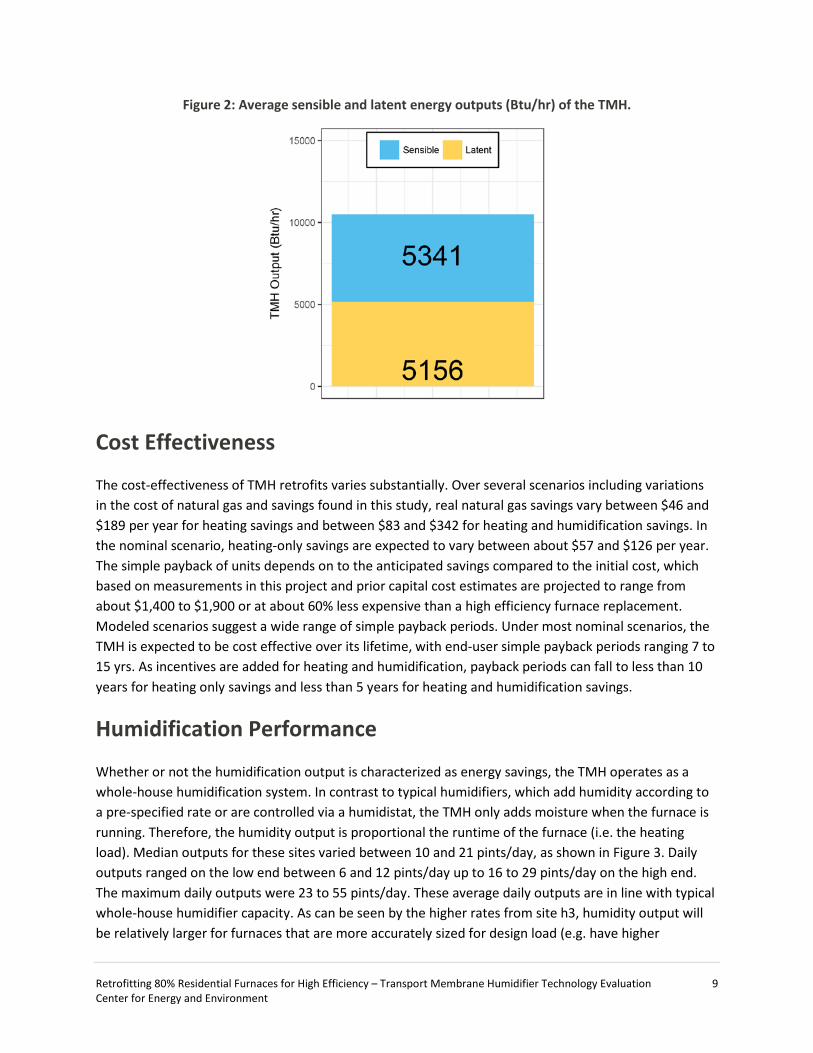
In Figure 2 the added furnace output is broken down into the average sensible and latent energy outputs of the furnace and TMH unit. The bulk of the energy (~80%) is added to the air flow via the furnace. An additional 5,300 Btu/hr is added by the TMH to increase the temperature of the return air delivered to the furnace heat exchanger. The TMH also adds 5,200 Btu/hr of energy by increasing the moisture (absolute humidity) of the return air flow delivered to the furnace heat exchanger.
Retrofitting 80% Residential Furnaces for High Efficiency – Transport Membrane Humidifier Technology Evaluation 9 Center for Energy and Environment
Figure 2: Average sensible and latent energy outputs (Btu/hr) of the TMH.
Cost Effectiveness
The cost-effectiveness of TMH retrofits varies substantially. Over several scenarios including variations in the cost of natural gas and savings found in this study, real natural gas savings vary between $46 and $189 per year for heating savings and between $83 and $342 for heating and humidification savings. In the nominal scenario, heating-only savings are expected to vary between about $57 and $126 per year. The simple payback of units depends on to the anticipated savings compared to the initial cost, which based on measurements in this project and prior capital cost estimates are projected to range from about $1,400 to $1,900 or at about 60% less expensive than a high efficiency furnace replacement. Modeled scenarios suggest a wide range of simple payback periods. Under most nominal scenarios, the TMH is expected to be cost effective over its lifetime, with end-user simple payback periods ranging 7 to 15 yrs. As incentives are added for heating and humidification, payback periods can fall to less than 10 years for heating only savings and less than 5 years for heating and humidification savings.
Humidification Performance
Whether or not the humidification output is characterized as energy savings, the TMH operates as a whole-house humidification system. In contrast to typical humidifiers, which add humidity according to a pre-specified rate or are controlled via a humidistat, the TMH only adds moisture when the furnace is running. Therefore, the humidity output is proportional the runtime of the furnace (i.e. the heating load). Median outputs for these sites varied between 10 and 21 pints/day, as shown in Figure 3. Daily outputs ranged on the low end between 6 and 12 pints/day up to 16 to 29 pints/day on the high end. The maximum daily outputs were 23 to 55 pints/day. These average daily outputs are in line with typical whole-house humidifier capacity. As can be seen by the higher rates from site h3, humidity output will be relatively larger for furnaces that are more accurately sized for design load (e.g. have higher

Retrofitting 80% Residential Furnaces for High Efficiency – Transport Membrane Humidifier Technology Evaluation 10 Center for Energy and Environment
runtime). The major difference is that the energy for vaporizing moisture comes from the flue gas in contrast to other whole house humidification systems, which take heat from the furnace air. In practice, humidity output is proportional to the humidification demand; meaning that the TMH outputs more humidity during cold, dry weather as shown in Figure 4. The TMH output is higher at the lowest outside air temperature and decreases with increasing outside air temperature.
Figure 3: Range of TMH humidifier outputs for each site
Figure 4: TMH humidity output increases with decreasing outside air temperature
The most significant task in this study after the validation of TMH performance was the assessment of the impact on the indoor environment. The potential for excess humidification from the introduction of an indirectly controlled humidifier system raised concerns about indoor air quality, the potential for

Retrofitting 80% Residential Furnaces for High Efficiency – Transport Membrane Humidifier Technology Evaluation 11 Center for Energy and Environment
microbial growth, and the long-term impacts of increasing wintertime humidity. However, excess humidification was not observed in sites experiencing a wide range of baseline relative humidity, from less than 20% to over 60%. During cold weather (below freezing), the TMH increased relative humidity by 5% to 10%. Above freezing, the TMH output was significantly reduced due low runtimes (output) compared to the rate of humidity exchange with the environment. Sensors placed in structural lumber also showed that the increased humidity levels from TMH operation did not impact the seasonal drying cycle of the homes.
Conclusion This study found that the TMH technology improved the furnace system efficiency while markedly improving indoor humidity levels during cold, dry weather. The TMH adds about 5,300 Btu/hr to the furnace output yielding 9% natural gas savings. The TMH also adds 5,200 Btu/hr through the humidification of return air, which is either an additional 9% of energy savings or simply a non-energy benefit of improved comfort.
This study included sites that had indoor humidity levels ranging from less than 20% to over 60%. On average, the TMH increased indoor humidity levels between 5% and 10% below outside air temperatures of 32ᵒF. Humidifier output during the coldest weather is typically 15 to 60 pints/day. Excess or runaway humidification was not observed and wood moisture monitoring showed that, even in a high humidity home, the increased levels of relative humidity were insufficient to interrupt the natural drying cycle.
Total projected installed costs are anticipated to be about 60% less than a high efficiency furnace upgrade (NREL, 2017) or about $1,400 to $1,900 or less with future optimization. Several savings and payback scenarios were modeled. Payback is highly variable (i.e. 2.8 to 53 years) and is most sensitive to: 1) space heating load, 2) inclusion of humidification savings, and 3) potential incentives. The nominal savings scenarios indicate that TMH units are cost effective over their lifetime (7- 15 yr), making the TMH a compelling alternative compared to a furnace replacement, especially for late-model furnaces and those units with a decade or more of remaining lifetime.
The TMH is a viable technology for achieving large natural gas savings for space heating in single-family homes. It is the only viable alternative to a condensing furnace upgrade and it is the cheaper option, particularly for the vast number of standard efficiency furnaces that will remain operational over the coming decades, which number in the hundreds of thousands. Still, the TMH is a pre-commercial technology that has not yet been taken up by a manufacturer for commercialization, and this current status remains the major barrier to adoption. Even under a fast transition to high-efficiency heating in the state, there remains a decade or more over which these barriers may be resolved and the TMH introduced for consequential energy savings and emissions reductions.

Retrofitting 80% Residential Furnaces for High Efficiency – Transport Membrane Humidifier Technology Evaluation 12 Center for Energy and Environment
Introduction
Space heating is the number one end use for energy in Minnesota buildings, and residential forced air furnaces consume more energy for space heating than any other type of heating device. Thus efficiency improvements for these furnaces have the potential for significant energy savings in Minnesota. However, to date the only way to increase the efficiency of a natural gas forced air furnace has been to replace it with a higher efficiency (i.e. 90 to 96%+) model, and there are several barriers to this approach. First, forced air furnaces have a long lifespan (often 20+ yr), reducing the opportunity for end of life replacement. Second, high-efficiency condensing units have high capital and installation costs due to different venting requirements than standard efficiency units. Third, given the high upfront costs, a condensing furnace upgrade comes with a long payback period at today’s low gas prices, affecting replacement decisions – particularly those prior to end of life. These barriers, along with the reduction of incentives for high efficiency furnaces, have caused market penetration to stall, leaving a substantial amount of potential gas savings on the table.
This project explored an alternative to furnace replacement as a way to achieve high efficiency space heating — an upgrade to residential standard efficiency furnaces called the transport membrane humidifier (TMH). The TMH saves energy by increasing the efficiency of induced draft furnaces from 76%-82% to the 90%+ efficiency level typically associated with condensing furnaces. The TMH extracts additional energy from the combustion process by recovering water vapor and waste heat from the furnace flue gas to preheat and humidify the inside (return) air during the heating season. It also acts as a whole house humidification appliance in addition to an energy efficiency technology. The TMH is constructed from a metal casing and ceramic membrane heat and mass exchange surfaces and is installed into the return air duct with a separate connection to the flue gas vent and wired into existing furnace controls.
TMH technology may offer the least intrusive, fastest way to save hundreds of millions of cubic feet of natural gas annually. By accessing the hundreds of thousands of standard efficiency furnaces that will remain operational until (and after) typical end of life, retrofitting existing furnaces with low-cost efficiency upgrades has the potential to achieve dramatic energy savings throughout Minnesota. In addition to energy savings, the TMH is a whole-house humidifier and may alleviate dryness typically associated cold weather, an important non-energy benefit to consider. This study investigated the potential energy savings and comfort benefits while also exploring the risks associated with increasing humidity levels and retrofitting existing equipment.
Background
TMH Technology
The TMH technology was developed by the Gas Technology Institute (GTI) as a novel humidification technology to overcome the problems typically associated with existing whole-house furnace-mounted
Retrofitting 80% Residential Furnaces for High Efficiency – Transport Membrane Humidifier Technology Evaluation 13 Center for Energy and Environment
humidifiers [1-4]. Humidification is often needed in cold climates due the very dry conditions that develop during winter months. It is generally accepted that moderate relative humidity (e.g. 30% to 60%) is beneficial to the comfort and health of building occupants. However, winter humidity in cold climates often falls below 20%, and can be as low as 10%, as buildings naturally lose moisture to extremely dry outside air. Despite these issues, humidification of homes is rare and existing technologies face several challenges.
Existing humidification technologies rely on forced air furnace-mounted bypass wetted media, spray mist, or steam humidifiers, which all require additional furnace heat or electricity to evaporate the water. Among the challenges these technologies face, portable units must be refilled often and whole-house units must be connected to fresh water supply. In addition, most of these technologies experience mineral deposition, white dust, and microbial growth problems. These humidifier technologies also require periodic maintenance, and operation is often subject to additional controls (humidistat) that must be properly configured and operated. Neglecting either of these can negatively impact performance or even basic functionality.
The TMH does not face any of the challenges with typical humidification technologies. It uses a nanoporous membrane to extract water vapor from furnace combustion flue gas. The mechanism that allows humidification — capillary condensation — yields sufficient water transport rates and blocks non-condensable combustion gases from entering building air. The added water is clean and mineral free, avoiding the need for regular maintenance or a clean source of water. The energy to evaporate the water is also directly extracted from remaining flue gas energy, which eliminates the energy cost associated with other humidifier technologies and provides an energy surplus, thus increasing furnace efficiency. The TMH also operates without additional controls, passively emitting humidity in proportion to the building’s humidification needs.
In the TMH, the driving force for transporting water vapor from the flue gas across the membrane surface is the difference in the water vapor partial pressure between the two gas streams. The moisture-rich flue gas stream typically has a very high dew point of 120°F to 136°F, especially compared to room air which usually has a dew point of 50˚F. This difference yields a high water vapor partial pressure difference on the order of 2 psi (13,800 Pa). This large driving force minimizes membrane surface area requirements, leading to a low-cost installation and improved prospects for commercial application. In addition, the high temperature flue gas (250˚F to 350˚F) allows the TMH to function as a secondary heat exchanger to preheat the building air and increase the system efficiency.
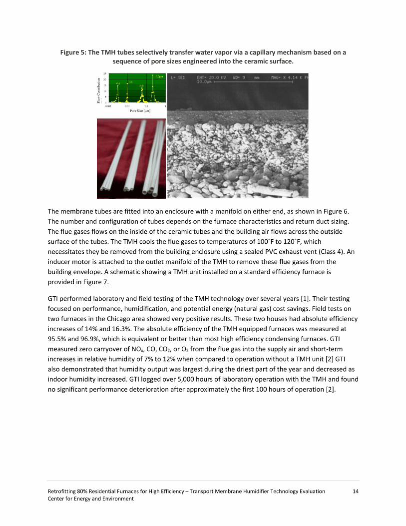
A TMH unit is made from many nanoporous membrane tubes. Figure 5 shows a photograph of the membrane tubes, a photomicrograph of a typical membrane tube cross section, and the distribution of pore sizes that facilitate the water transport. Each membrane tube consists of a top layer with a pore size of 60 to 80 Å (about 2 to 4 µm thick), an intermediate with layer 500 Å pore size (typically 20 to 50 µm thick), and a substrate layer with 0.4 µm pore size (about 1 mm thick). This sequence of pore sizes allows water from the flue gas to condense on the interior of the tube, move through the membrane structure as a liquid, and evaporate from the exterior of the tube into the building air. This structure is used to achieve high separation ratio with minimal transport resistance and very low pressure drop.
Retrofitting 80% Residential Furnaces for High Efficiency – Transport Membrane Humidifier Technology Evaluation 14 Center for Energy and Environment
Figure 5: The TMH tubes selectively transfer water vapor via a capillary mechanism based on a sequence of pore sizes engineered into the ceramic surface.
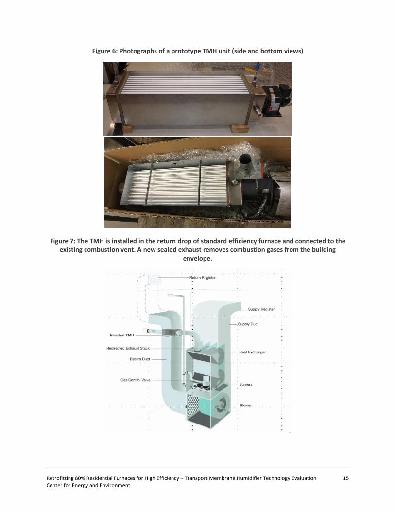
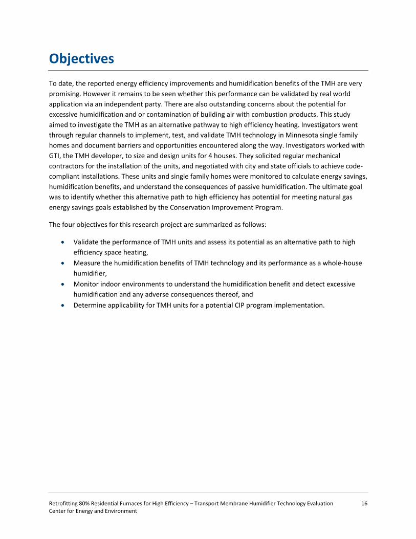
The membrane tubes are fitted into an enclosure with a manifold on either end, as shown in Figure 6. The number and configuration of tubes depends on the furnace characteristics and return duct sizing. The flue gases flows on the inside of the ceramic tubes and the building air flows across the outside surface of the tubes. The TMH cools the flue gases to temperatures of 100˚F to 120˚F, which necessitates they be removed from the building enclosure using a sealed PVC exhaust vent (Class 4). An inducer motor is attached to the outlet manifold of the TMH to remove these flue gases from the building envelope. A schematic showing a TMH unit installed on a standard efficiency furnace is provided in Figure 7.
GTI performed laboratory and field testing of the TMH technology over several years [1]. Their testing focused on performance, humidification, and potential energy (natural gas) cost savings. Field tests on two furnaces in the Chicago area showed very positive results. These two houses had absolute efficiency increases of 14% and 16.3%. The absolute efficiency of the TMH equipped furnaces was measured at 95.5% and 96.9%, which is equivalent or better than most high efficiency condensing furnaces. GTI measured zero carryover of NOx, CO, CO2, or O2 from the flue gas into the supply air and short-term increases in relative humidity of 7% to 12% when compared to operation without a TMH unit [2] GTI also demonstrated that humidity output was largest during the driest part of the year and decreased as indoor humidity increased. GTI logged over 5,000 hours of laboratory operation with the TMH and found no significant performance deterioration after approximately the first 100 hours of operation [2].
Retrofitting 80% Residential Furnaces for High Efficiency – Transport Membrane Humidifier Technology Evaluation 15 Center for Energy and Environment
Figure 6: Photographs of a prototype TMH unit (side and bottom views)
Figure 7: The TMH is installed in the return drop of standard efficiency furnace and connected to the existing combustion vent. A new sealed exhaust removes combustion gases from the building
envelope.
Retrofitting 80% Residential Furnaces for High Efficiency – Transport Membrane Humidifier Technology Evaluation 16 Center for Energy and Environment
Objectives To date, the reported energy efficiency improvements and humidification benefits of the TMH are very promising. However it remains to be seen whether this performance can be validated by real world application via an independent party. There are also outstanding concerns about the potential for excessive humidification and or contamination of building air with combustion products. This study aimed to investigate the TMH as an alternative pathway to high efficiency heating. Investigators went through regular channels to implement, test, and validate TMH technology in Minnesota single family homes and document barriers and opportunities encountered along the way. Investigators worked with GTI, the TMH developer, to size and design units for 4 houses. They solicited regular mechanical contractors for the installation of the units, and negotiated with city and state officials to achieve code-compliant installations. These units and single family homes were monitored to calculate energy savings, humidification benefits, and understand the consequences of passive humidification. The ultimate goal was to identify whether this alternative path to high efficiency has potential for meeting natural gas energy savings goals established by the Conservation Improvement Program.
The four objectives for this research project are summarized as follows:
• Validate the performance of TMH units and assess its potential as an alternative path to high efficiency space heating,
• Measure the humidification benefits of TMH technology and its performance as a whole-house humidifier,
• Monitor indoor environments to understand the humidification benefit and detect excessive humidification and any adverse consequences thereof, and
• Determine applicability for TMH units for a potential CIP program implementation.

Retrofitting 80% Residential Furnaces for High Efficiency – Transport Membrane Humidifier Technology Evaluation 17 Center for Energy and Environment
Methodology
This project is primarily a field study of the TMH technology. The study methodology can be divided into four main sections: (1) identify and select variables influencing TMH outcomes for site selection; (2) design prototype TMH units for the research sites; (3) develop experimental program to measure TMH field performance and perform long-term monitoring of units and indoor air conditions, and (4) develop analysis framework to estimate performance, humidification benefits, and energy savings.
Site Selection
Indoor Humidity Levels
The indoor humidity environment of single-family homes is complicated; it varies seasonally and depends on many occupant behaviors and building characteristics. Data for typical indoor humidity levels are unavailable and characterizing representative levels of humidity was beyond the scope of this study. Nonetheless, an attempt was made to characterize the expected humidity levels in single-family houses based on available data. The goal was to select sites that represent a range of humidity environments in Minnesota homes so that humidification needs and the risks associated with excessive humidification could be evaluated in the context of widespread TMH deployment.
Single-family homes were characterized from available data corresponding to important factors for indoor humidity during cold weather. Mechanical ventilation and infiltration/exfiltration replace indoor air with outdoor air. In cold weather, homes dry out because the moisture content of outdoor air is much less than that of the warm indoor air (Figure 8). Moisture is generated in buildings from its occupants. Moisture sources include the evaporation of hot water (e.g. showers, cooking, air-drying), respiration and transpiration (e.g. occupants, pets, and plants), and it can be added with portable and whole-house mechanical humidification systems. In the Minnesota heating season, when the rate of moisture generation is less than the rate of its exchange with the outside air, interior humidity increases. Interior humidity decreases when the rate of humidity exchange is higher than the rate of internal humidity generation.
In practice, generation and exchange rates are highly variable from house to house and depend on many factors. Thus, generation and exchange rates are unknowable without extensive measurements. In lieu of these data, other available data were used to capture these effects. Envelope tightness was assumed to be a reasonable proxy for the tendency of air leakage to dry out homes in the winter. The rate of moisture generation was assumed to be proportional to occupant density because moisture generation scales with the number occupants (e.g. respiration and hot water use.) Furthermore, datasets for both of these parameters exist enabling this project to draw upon a representative sample.

Retrofitting 80% Residential Furnaces for High Efficiency – Transport Membrane Humidifier Technology Evaluation 18 Center for Energy and Environment
Figure 8: Absolute indoor humidity varies throughout the year and is typically much less than desired indoor humidity during heating season.
Air tightness measurements from several thousand Minnesota homes provided the characterization data necessary to determine the range that could be anticipated in Minnesota homes [5]. Census data and Residential Energy Consumption Survey (RECS2009) data provided information on number of occupants and single-family home size, and these were used to characterize the range of occupant density in Minnesota [5-7]. Figures were updated with recent state-wide residential survey data [8].
Table 1: Parameters and values for estimating indoor humidity environments to target
Air Tightness Ratio (cfm50/ft2)
Occupant Density (people/1000 ft2) Description
0.86 (30th %) 1.14 (55th %) Tight envelope with median occupant density
0.86 (30th %) 2.04 (85th %) Tight envelope with high occupant density
1.25 (70th %) 1.14 (55th %) Drafty envelope with median occupant density
1.25 (70th %) 2.04 (85th %) Drafty envelope with high occupant density
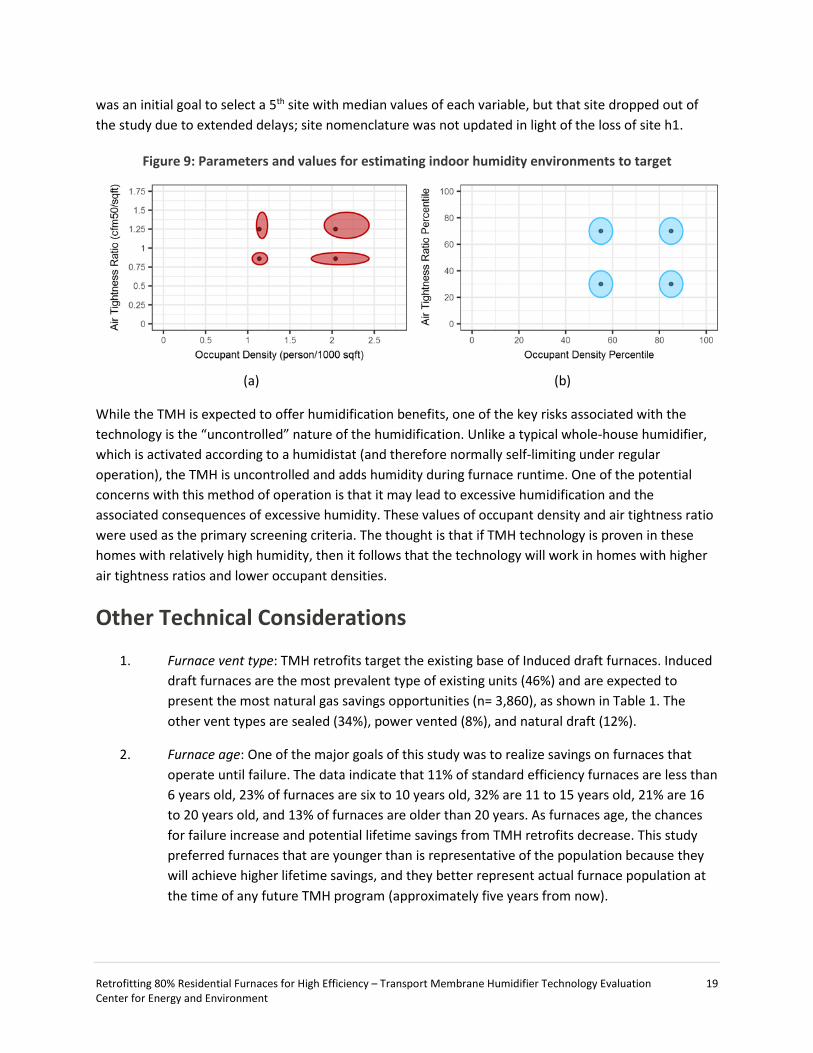
Air tightness ratio (cfm50/ft2) and occupant density (person/1000-ft2) established the parametric space for site selection. The 30th and 70th percentiles of the envelope tightness targets established for the study associated with typical homes, avoiding extremely leaky and extremely tight homes. The 55th and the 85th percentiles were selected as targets for the occupant density. These high values of occupant density were selected to focus on houses that may have relatively high humidity generation and thus more sensitivity to over humidification from humidifier operation. The values for these parameters were assigned the four qualitative descriptions in Table 1. These four targets are visualized in Figure 9 in terms of absolute values and the population percentiles. The shaded regions represent variations of ±10% on air tightness ratio and ±5% on occupant density to allow some flexibility in site selection. There
Retrofitting 80% Residential Furnaces for High Efficiency – Transport Membrane Humidifier Technology Evaluation 19 Center for Energy and Environment
was an initial goal to select a 5th site with median values of each variable, but that site dropped out of the study due to extended delays; site nomenclature was not updated in light of the loss of site h1.
Figure 9: Parameters and values for estimating indoor humidity environments to target
(a)
(b)
While the TMH is expected to offer humidification benefits, one of the key risks associated with the technology is the “uncontrolled” nature of the humidification. Unlike a typical whole-house humidifier, which is activated according to a humidistat (and therefore normally self-limiting under regular operation), the TMH is uncontrolled and adds humidity during furnace runtime. One of the potential concerns with this method of operation is that it may lead to excessive humidification and the associated consequences of excessive humidity. These values of occupant density and air tightness ratio were used as the primary screening criteria. The thought is that if TMH technology is proven in these homes with relatively high humidity, then it follows that the technology will work in homes with higher air tightness ratios and lower occupant densities.
Other Technical Considerations
1. Furnace vent type: TMH retrofits target the existing base of Induced draft furnaces. Induced draft furnaces are the most prevalent type of existing units (46%) and are expected to present the most natural gas savings opportunities (n= 3,860), as shown in Table 1. The other vent types are sealed (34%), power vented (8%), and natural draft (12%).
2. Furnace age: One of the major goals of this study was to realize savings on furnaces that operate until failure. The data indicate that 11% of standard efficiency furnaces are less than 6 years old, 23% of furnaces are six to 10 years old, 32% are 11 to 15 years old, 21% are 16 to 20 years old, and 13% of furnaces are older than 20 years. As furnaces age, the chances for failure increase and potential lifetime savings from TMH retrofits decrease. This study preferred furnaces that are younger than is representative of the population because they will achieve higher lifetime savings, and they better represent actual furnace population at the time of any future TMH program (approximately five years from now).
Retrofitting 80% Residential Furnaces for High Efficiency – Transport Membrane Humidifier Technology Evaluation 20 Center for Energy and Environment
3. Furnace make: As compatible with earlier requirements, TMH units were installed on a variety of different furnace manufacturers. Potential manufacturers included Amana, American Standard, Bryant, Carrier, Coleman, Goodman, Lennox, Nordyne, Rheem, and York.
4. Other factors:
a. Basic furnace evaluation and CO flue gas measurements: Furnace integrity was evaluated and CO measured in the flue gas at each site. Burners were checked for fouling, alignment, and impingement, and the heat exchanger was checked for warping and fouling. CO was measured in the flue gas at light off until levels stabilized. If CO levels exceeded 100ppm after light off or were increasing, furnace inspection and tune up were performed or the site was disqualified. No sites were disqualified due to furnace condition.
b. Furnace AFUE: Limited AFUE data for induced fan furnaces suggest AFUE range 76 to 82, and TMH performance is not expected to vary significantly within this range.
c. Furnace size: Although furnace size reportedly has little effect on TMH performance, it does influence TMH sizing and the amount of moisture generated by each TMH unit. It was anticipated that a variety of furnace sizes would be selected upon meeting the primary requirements.
d. House size: Normalizing the key parameters (occupancy and envelope tightness) by the floor area includes information about house size. While important variables scale with size (e.g. factors depending on surface area to volume ratio), such effects were deemed less consequential and are left to a future study.
Screening
Site selection proceeded according to the following process: 1. Identify candidate houses based on air tightness ratio (cfm50/ft2). 2. Calculate occupants necessary to meet targets (Table 1).
a. Use existing estimates of house size from data in step 1. 3. Call candidates to determine occupants.
a. Confirm house size. b. Determine whether basement is heated or otherwise substantially well connected to
the primary living space (i.e. included in size estimate). 4. Follow up with candidates.
a. Determine furnace type/age, and b. Gauge willingness to participate and schedule a follow-up visit.
5. Perform a house visit and follow screening form a. Note any unusual humidity related details. b. Measure air tightness. c. Secure participation.

Retrofitting 80% Residential Furnaces for High Efficiency – Transport Membrane Humidifier Technology Evaluation 21 Center for Energy and Environment
Design TMH units were sized according to rated furnace capacity, airflow rate, and the dimensions of the return drop. The TMH units were similar except for their dimensions and membrane surface area (the number and dimensions of the ceramic membrane tubes). Each TMH unit was equipped with the same induced draft blower and manufactured according to the same process. A sample design for TMH unit h3 is given in Appendix A.
Experimental Procedure TMH devices were installed in four sites. The units and sites were instrumented and performance was continuously monitored to facilitate a comparison between baseline furnace operation and TMH operation. While the units were primarily operated in TMH mode, they were alternated into bypass mode for 10 to 21 days once per season (i.e. fall, winter, and spring). During bypass mode, flue gases escaped via the regular induced draft vertical vent and the TMH unit and its controls were disabled.
The alternate mode testing was enabled by some additional controls to disable the TMH inducer fan and pressure switch when necessary. A set of dampers were manually adjusted to direct flue gases into the TMH or the conventional flue. Modes were alternated by investigators during routine visits or by participants themselves.
Table 2: Continuous measurements
Measurement Sensor Uncertainty Furnace supply air
temperature Type-T thermopile ±0.2 ᵒF
Furnace return air temperature
Type-T thermopile ±0.2 ᵒF
TMH inlet temperature Type-T thermocouple ±0.6 ᵒF TMH outlet temperature Type-T thermocouple ±0.6 ᵒF TMH flue inlet humidity OMEGA HX94C ±3 %
TMH flue outlet humidity OMEGA HX94C ±3 % Ambient temperature* Omnisense S1 ±0.7 ᵒF
Ambient humidity* Omnisense S1 ±3.5 % Wood moisture content*,** Omnisense S1 -
* Located in basement, thermostat, and second story or attic ** Not available at all locations
Each furnace system was outfitted with sensors to measure the energy of the air stream at key inlet and outlet locations in the furnace-TMH system. Data measured continuously are given in Table 2. Each TMH device was instrumented with thermocouples (Type-T ±1ᵒF) to measure the inlet and outlet air temperature on both sides (i.e. building air and flue gas). Relative humidity probes (OMEGA HX94C±3 %) were placed on the inlet and outlet of the air side of the TMH to measure change of latent energy. Triple-junction thermopiles (Type-T SLE ±0.3ᵒF) were placed in the supply and return air ducts to
Retrofitting 80% Residential Furnaces for High Efficiency – Transport Membrane Humidifier Technology Evaluation 22 Center for Energy and Environment
measure the overall change in temperature across the TMH-furnace system. Each of these sensor readings were recorded using Logic Beach IL-80 data logger with a cellular modem. The data were recorded at 10 second intervals and retrieved weekly.
A second, cloud-based wireless measurement platform called Omnisense (S1 ±0.7 ᵒF / 3.5% RH) was used to measure the ambient temperature and relative humidity at three locations per site. These locations were typically in the basement, near the thermostat, and in the second story or attic. Where possible these sensors also recorded wood moisture content of studs or joists. These data were recorded at five-minute intervals and saved to a cloud platform in real time. Data were retrieved on a weekly basis.
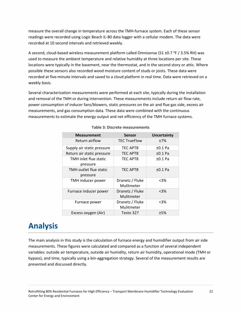
Several characterization measurements were performed at each site, typically during the installation and removal of the TMH or during intervention. These measurements include return air flow rate, power consumption of inducer fans/blowers, static pressures on the air and flue gas side, excess air measurements, and gas consumption data. These data were combined with the continuous measurements to estimate the energy output and net efficiency of the TMH furnace systems.
Table 3: Discrete measurements
Measurement Sensor Uncertainty Return airflow TEC TrueFlow ±7%
Supply air static pressure TEC APT8 ±0.1 Pa Return air static pressure TEC APT8 ±0.1 Pa
TMH inlet flue static pressure
TEC APT8 ±0.1 Pa
TMH outlet flue static pressure
TEC APT8 ±0.1 Pa
TMH inducer power Dranetz / Fluke Mulitmeter
<3%
Furnace inducer power Dranetz / Fluke Mulitmeter
<3%
Furnace power Dranetz / Fluke Mulitmeter
<3%
Excess oxygen (Air) Testo 327 ±5%
Analysis The main analysis in this study is the calculation of furnace energy and humidifier output from air side measurements. These figures were calculated and compared as a function of several independent variables: outside air temperature, outside air humidity, return air humidity, operational mode (TMH or bypass), and time, typically using a bin-aggregation strategy. Several of the measurement results are presented and discussed directly.

Retrofitting 80% Residential Furnaces for High Efficiency – Transport Membrane Humidifier Technology Evaluation 23 Center for Energy and Environment
Performance and Savings
The TMH and furnace performance were evaluated based on steady-state output rates (Btu/hr) and net furnace-system efficiency (%). Air side energy output 𝐸𝐸𝑜𝑜𝑜𝑜𝑜𝑜 (Btu/hr) is equivalent to the sensible (temperature) and latent (humidity) energy additions by the furnace system.
𝐸𝐸𝑜𝑜𝑜𝑜𝑜𝑜 = 𝐸𝐸𝑠𝑠𝑠𝑠𝑠𝑠𝑠𝑠𝑠𝑠𝑠𝑠𝑠𝑠𝑠𝑠 + 𝐸𝐸𝑠𝑠𝑙𝑙𝑜𝑜𝑠𝑠𝑠𝑠𝑜𝑜
The first term on the right hand side is the sensible energy component and the second term is the latent energy component.
𝐸𝐸𝑠𝑠𝑠𝑠𝑠𝑠𝑠𝑠𝑠𝑠𝑠𝑠𝑠𝑠𝑠𝑠 = 𝑄𝑄𝑙𝑙𝑠𝑠𝑎𝑎𝜌𝜌𝑙𝑙𝑠𝑠𝑎𝑎𝑐𝑐𝑝𝑝�𝑇𝑇𝑠𝑠𝑜𝑜𝑝𝑝𝑝𝑝𝑠𝑠𝑠𝑠 − 𝑇𝑇𝑎𝑎𝑠𝑠𝑜𝑜𝑜𝑜𝑎𝑎𝑠𝑠�
𝐸𝐸𝑠𝑠𝑙𝑙𝑜𝑜𝑠𝑠𝑠𝑠𝑜𝑜 = 𝑄𝑄𝑙𝑙𝑠𝑠𝑎𝑎𝜌𝜌𝑙𝑙𝑠𝑠𝑎𝑎𝑓𝑓ℎ𝑓𝑓𝑓𝑓(𝑤𝑤𝑜𝑜𝑜𝑜𝑜𝑜 − 𝑤𝑤𝑠𝑠𝑠𝑠)
Where 𝑄𝑄𝑙𝑙𝑠𝑠𝑎𝑎 is the volume flow rate of return air (ft3/hr), 𝜌𝜌 is the average air-side density (lbm-air/ft3), 𝑐𝑐𝑝𝑝 is the air-side specific heat (Btu/lbm-air-ᵒF), 𝑇𝑇𝑎𝑎𝑠𝑠𝑜𝑜𝑜𝑜𝑎𝑎𝑠𝑠 and 𝑇𝑇𝑠𝑠𝑜𝑜𝑝𝑝𝑝𝑝𝑠𝑠𝑠𝑠 are the temperatures in and out of the TMH-furnace system (ᵒF), ℎ𝑓𝑓𝑓𝑓 is the latent heat of vaporization (Btu/lbm-H2O), and 𝑤𝑤𝑠𝑠𝑠𝑠 and 𝑤𝑤𝑜𝑜𝑜𝑜𝑜𝑜 are the absolute humidity levels of the air in and out of the TMH (lbm-H2O/lbm-air).
The efficiency, 𝜂𝜂, is equivalent to the energy out divided by the flow rate of natural gas, 𝑄𝑄𝑠𝑠𝑓𝑓 (ft3/hr), and the heating value (HHV) of the delivered natural gas (Btu/ft3). Heating system efficiency is calculated under two assumptions, depending on the whether the TMH is displacing an existing humidification device. If no prior humidification takes place, the latent energy term is tallied separately from the sensible energy term and only included as a non-energy benefit. When the TMH displaces existing or anticipated humidification loads, the latent energy term is included.
𝜂𝜂𝑠𝑠𝑠𝑠𝑠𝑠𝑠𝑠 =𝐸𝐸𝑠𝑠𝑠𝑠𝑠𝑠𝑠𝑠
𝑄𝑄𝑠𝑠𝑓𝑓𝐻𝐻𝐻𝐻𝐻𝐻
𝜂𝜂𝑜𝑜𝑜𝑜𝑜𝑜 =𝐸𝐸𝑜𝑜𝑜𝑜𝑜𝑜
𝑄𝑄𝑠𝑠𝑓𝑓𝐻𝐻𝐻𝐻𝐻𝐻
Combustion side efficiency measurements are also used as a comparison to the air-side measurements following [2]. This efficiency is calculated based on the energy released via combustion minus the loss of sensible and latent energy in the flue gases.
𝜂𝜂𝑐𝑐𝑠𝑠 = 𝑄𝑄𝑠𝑠𝑓𝑓𝐻𝐻𝐻𝐻𝐻𝐻 − 𝑄𝑄𝑓𝑓𝑓𝑓𝜌𝜌𝑓𝑓𝑓𝑓𝑐𝑐𝑝𝑝𝑓𝑓𝑓𝑓�𝑇𝑇𝑓𝑓𝑓𝑓,𝑜𝑜𝑜𝑜𝑜𝑜 − 𝑇𝑇𝑓𝑓𝑓𝑓,𝑠𝑠𝑠𝑠� − 𝑄𝑄𝑓𝑓𝑓𝑓𝜌𝜌𝑓𝑓𝑓𝑓𝑤𝑤𝑓𝑓𝑓𝑓,𝑜𝑜𝑜𝑜𝑜𝑜ℎ𝑓𝑓𝑓𝑓
𝑄𝑄𝑠𝑠𝑓𝑓𝐻𝐻𝐻𝐻𝐻𝐻
Normalized (gas) energy savings (%) for space heating are the direct outcome of the change in furnace efficiency from bypass mode to TMH mode.
𝐺𝐺𝑠𝑠𝑙𝑙𝑠𝑠𝑠𝑠𝑠𝑠𝑓𝑓𝑠𝑠 =𝜂𝜂𝑠𝑠𝑠𝑠𝑠𝑠𝑠𝑠,𝑇𝑇𝑇𝑇𝑇𝑇 𝑜𝑜𝑜𝑜 𝜂𝜂𝑜𝑜𝑜𝑜𝑜𝑜,𝑇𝑇𝑇𝑇𝑇𝑇
𝜂𝜂𝑠𝑠𝑠𝑠𝑝𝑝𝑙𝑙𝑠𝑠𝑠𝑠
Retrofitting 80% Residential Furnaces for High Efficiency – Transport Membrane Humidifier Technology Evaluation 24 Center for Energy and Environment
Typical savings estimates are produced for each home based on the time they were installed, for each full year of the study and a typical meteorological year (TMY3). Normalized TMY3 results are used for calculating simple payback and cost-effectiveness estimates for broad savings projections.
Energy use is calculated from by integrating furnace output 𝐸𝐸𝑜𝑜𝑜𝑜𝑜𝑜, 𝐸𝐸𝑠𝑠𝑠𝑠𝑠𝑠𝑠𝑠, 𝑜𝑜𝑜𝑜 𝐸𝐸𝑠𝑠𝑙𝑙𝑜𝑜𝑠𝑠𝑠𝑠𝑜𝑜 over the variable of interest, i.e. cycle or outside air temperature.
Humidifier Performance
Humidity produced by the TMH during furnace operation (lbm-H2O/hr) depends on the air flow rate, the air density, and the absolute humidity added to the airstream by the TMH. These data are expressed as volume water output (i.e. Pints/day) consistent with conventional humidification systems.
𝐻𝐻𝑜𝑜𝑜𝑜𝑜𝑜 = 𝑄𝑄𝑙𝑙𝑠𝑠𝑎𝑎𝜌𝜌(𝑤𝑤𝑜𝑜𝑜𝑜𝑜𝑜 − 𝑤𝑤𝑠𝑠𝑠𝑠)
Weather - Normalization
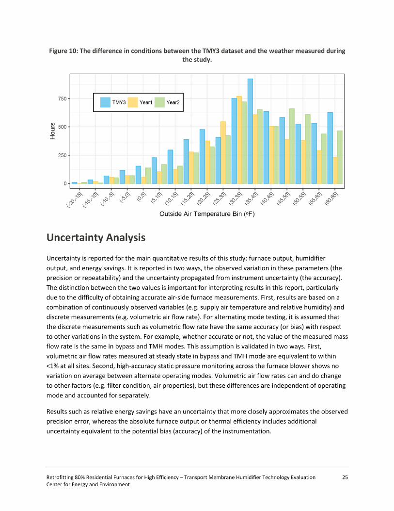
Performance data are normalized to the Typical Meteorological Year (TMY3) dataset to estimate a weather-normalized heating load and typical energy savings values [9]. The normalization is performed using a binning procedure, whereby the measurements are aggregated into 5 ᵒF bins from -25 ᵒF to 65 ᵒF using local NOAA outside air temperature values. The imputed bin values of the measurements are then used to calculate the normalized values based on the distribution of outside air temperature in the typical meteorological year data. In addition to correcting for differences in weather, the process also adjusts for missing data. In practice, measurements change very little between outside air temperature bins because the furnace operation is not temperature dependent. The main effect is to compute a normalized heating load, which is then used to calculate typical savings values. The difference between the tmy3 data used for normalization and the weather measured during this study is shown in Figure 10.
Retrofitting 80% Residential Furnaces for High Efficiency – Transport Membrane Humidifier Technology Evaluation 25 Center for Energy and Environment
Figure 10: The difference in conditions between the TMY3 dataset and the weather measured during the study.
Uncertainty Analysis
Uncertainty is reported for the main quantitative results of this study: furnace output, humidifier output, and energy savings. It is reported in two ways, the observed variation in these parameters (the precision or repeatability) and the uncertainty propagated from instrument uncertainty (the accuracy). The distinction between the two values is important for interpreting results in this report, particularly due to the difficulty of obtaining accurate air-side furnace measurements. First, results are based on a combination of continuously observed variables (e.g. supply air temperature and relative humidity) and discrete measurements (e.g. volumetric air flow rate). For alternating mode testing, it is assumed that the discrete measurements such as volumetric flow rate have the same accuracy (or bias) with respect to other variations in the system. For example, whether accurate or not, the value of the measured mass flow rate is the same in bypass and TMH modes. This assumption is validated in two ways. First, volumetric air flow rates measured at steady state in bypass and TMH mode are equivalent to within <1% at all sites. Second, high-accuracy static pressure monitoring across the furnace blower shows no variation on average between alternate operating modes. Volumetric air flow rates can and do change to other factors (e.g. filter condition, air properties), but these differences are independent of operating mode and accounted for separately.
Results such as relative energy savings have an uncertainty that more closely approximates the observed precision error, whereas the absolute furnace output or thermal efficiency includes additional uncertainty equivalent to the potential bias (accuracy) of the instrumentation.
Retrofitting 80% Residential Furnaces for High Efficiency – Transport Membrane Humidifier Technology Evaluation 26 Center for Energy and Environment
Results
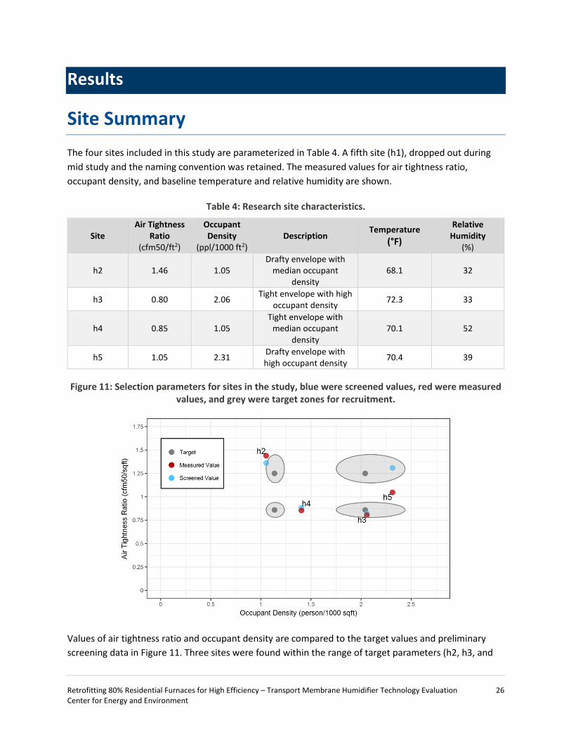
Site Summary The four sites included in this study are parameterized in Table 4. A fifth site (h1), dropped out during mid study and the naming convention was retained. The measured values for air tightness ratio, occupant density, and baseline temperature and relative humidity are shown.
Table 4: Research site characteristics.
Site Air Tightness
Ratio (cfm50/ft2)
Occupant Density
(ppl/1000 ft2) Description
Temperature (°F)
Relative Humidity
(%)
h2 1.46 1.05 Drafty envelope with
median occupant density
68.1 32
h3 0.80 2.06 Tight envelope with high occupant density 72.3 33
h4 0.85 1.05 Tight envelope with
median occupant density
70.1 52
h5 1.05 2.31 Drafty envelope with high occupant density 70.4 39
Figure 11: Selection parameters for sites in the study, blue were screened values, red were measured values, and grey were target zones for recruitment.
Values of air tightness ratio and occupant density are compared to the target values and preliminary screening data in Figure 11. Three sites were found within the range of target parameters (h2, h3, and

Retrofitting 80% Residential Furnaces for High Efficiency – Transport Membrane Humidifier Technology Evaluation 27 Center for Energy and Environment
h5); however, updated measurements pushed two sites (h2 and h5) outside this range. Despite non-target values, these sites were retained for the study due to difficulty recruiting sites with desired occupant density and air tightness parameters. Sites h4 and h5 tended toward higher existing humidity levels (deemed acceptable for this study’s goals) and h2 was not significantly outside the range. Air tightness ratio and occupant density show little correlation with baseline relative humidity levels (Figure 12). Sites h3 and h4 were anticipated to have higher levels than h2 and h5. In practice, the baseline relative humidity at site h4 was between 40% and 60%, significantly higher than the other sites in the study. Sites h2, h4, and h5 had nominally the same baseline humidity below 45°F, ranging between 20% and 40%. Above 45°F, the baseline relative humidity at h5was nominally similar to h4, between 55% and 60%, whereas relative humidity levels at h2 and h4 were consistently below 50%. Below about 25°F, sites h2, h3, and h5 had humidity levels typically associated with dryness and discomfort (<25%). On the other hand, h4 had a high humidity environment. No sites used humidification systems during the study, although prior to the study h5 occupants occasionally operated portable humidifiers at night. These varying baseline conditions are deemed sufficiently diverse to give context to the existing environments in which TMH units may be installed.
Figure 12: Baseline indoor relative humidity at each site as a function of outside air temperature.
Despite a variety of thermostat types and settings, average common space temperatures were similar across all sites (68ᵒF to 72ᵒF). Site h4 used a non-programmable thermostat set at 70ᵒF with no adjustment. Site h5 used a programmable thermostat that was not programmed, but was periodically manually adjusted between 70ᵒF and 72ᵒF. Site h2 used a programmable thermostat that included both daytime and nighttime setbacks and saw frequent manual adjustment. Site h3 used a learning thermostat and was periodically manually adjusted. Except for a short period of troubleshooting at site h5, thermostat settings and behaviors were the same during both TMH and bypass modes.

Retrofitting 80% Residential Furnaces for High Efficiency – Transport Membrane Humidifier Technology Evaluation 28 Center for Energy and Environment
The difficulty in finding adequate combinations of air tightness ratio and occupant density drove the selection process. The other remaining criteria regarding furnace details are listed in Table 5. At the four selected sites, all had induced draft furnaces with 80% AFUE ratings from four different manufacturers. Their rated sizes varied between 75 kBtu/hr and 88 kBtu/hr, and they were older than desired, between 16 and 27 years. Nonetheless, the units were found in proper working order and passed inspection by a master furnace technician.
Table 5: Furnace details
Site Furnace Make Model
Vent Type Age* (yr)
Size (BTU/hr)
Output (BTU/hr)
AFUE (%)
Airflow** (cfm)
h2 Bryant 383KAV Induced draft 16 88,000 71,000 80.6 915 h3 Rudd UGPH07EAVER Induced draft 19 75,000 60,450 80.6 960 h4 ArcoAire GUA080A012AIN Induced draft 27 80,000 64,000 80 870 h5 Goodman GMPV075-1.5/3 Induced draft 21 75,000 60,000 80 821
*Age at time of TMH install **Initial measurement
All four sites were monitored for at least a full heating season (about six to seven months), and site h4 was monitored for two seasons (12 months over two years). Maximum and minimum temperatures and relative humidity levels are shown for each site in Table 6. All sites experienced a full range of outside conditions typical of Minneapolis, from below design temperature all the way through balance point temperature. In general, there is less bypass data at lower outside air temperatures and less TMH data near the balance point. This is a consequence of the manual adjustment between modes and pre-determined bypass and TMH mode schedules.
Table 6: Study period characteristics
Site Monitoring Period (d)
Heating Season
(d)
Min. OAT (ᵒF)
Max. OAT (ᵒF)
Median Heating OAT (ᵒF)
Min. OAW
(lbm/lbm)
Max. OAW
(lbm/lbm)
Med. OAW
(lbm/lbm) h2 185 163 -19.5 65.0 36.0 2.7E-4 1.1E-2 3.0E-3 h3 228 207 -19.6 64.9 39.4 2.7E-4 1.2E-2 3.5E-3 h4 542 367 -19.5 65.0 37.5 2.7E-4 1.2E-2 3.3E-3 h5 222 183 -19.4 64.7 37.0 2.7E-4 1.1E-2 3.2E-3
Field Performance The TMH field performance was estimated for each of the four sites based on data summarized in Table 7. With the exception of site h2, results summarize average performance of thousands of furnace cycles over all Minneapolis space heating conditions. Site h4 had two seasons of alternate mode testing for a total of 2,474 cycles and 194 days. Sites h3 and h5 each had one full season of operation yielding 1,550 and 1,174 cycles over 139 and 118 days, respectively. Due to a TMH manufacturing defect, site h2 primarily operated in bypass mode and 40 furnace cycles were completed in TMH mode over seven days throughout the heating season. Typical bypass furnace cycles in the study ranged between about 780 and 1,200 seconds long and were 5% to 12% shorter in TMH mode than in bypass mode. The time for
Retrofitting 80% Residential Furnaces for High Efficiency – Transport Membrane Humidifier Technology Evaluation 29 Center for Energy and Environment
the furnace system to achieve steady state was either the same to slightly longer in TMH mode compared to bypass mode.
Table 7: Furnace/TMH operating characteristics
TMH Bypass
Site Days Furnace cycles
Average Steady
state time (s)
Average Cycle time
(s) Days Furnace
cycles
Average Steady
state time (s)
Average Cycle time
(s)
h2 7 40 489 965 126 1594 442 1099 h3 139 1550 489 1133 68 604 448 1187 h4 194 2474 138 830 173 1248 134 872 h5 118 1174 382 733 65 856 389 781
Space Heating Performance Summary
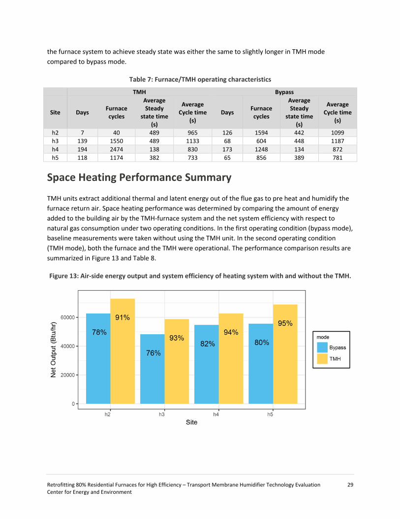
TMH units extract additional thermal and latent energy out of the flue gas to pre heat and humidify the furnace return air. Space heating performance was determined by comparing the amount of energy added to the building air by the TMH-furnace system and the net system efficiency with respect to natural gas consumption under two operating conditions. In the first operating condition (bypass mode), baseline measurements were taken without using the TMH unit. In the second operating condition (TMH mode), both the furnace and the TMH were operational. The performance comparison results are summarized in Figure 13 and Table 8.
Figure 13: Air-side energy output and system efficiency of heating system with and without the TMH.
Retrofitting 80% Residential Furnaces for High Efficiency – Transport Membrane Humidifier Technology Evaluation 30 Center for Energy and Environment
Table 8: Furnace performance figures for baseline and TMH operating modes.
Bypass TMH Improvement
Site Sensible Output (Btu/hr)
η (%)
Sensible Output (Btu/hr)
Latent Output (Btu/hr)
η (%)
Gas Savings
(%)
Gas Savings w/ Humidification
(%) h2 62,600 78.0±2 70,500 2,400 90.7±3.7 12.5 16.4 h3 48,400 76.1±1.7 52,800 6,100 92.9±3 9.1 21.4 h4 54,700 82.1±3.9 57,500 5,200 94.1±5.8 5.0 14.5 h5 57,700 80.0±2.6 64,100 6,900 95.4±4.3 11.0 19.5
In bypass mode, these standard efficiency furnaces had average energy outputs ranging from 48,400 Btu/hr to 62,600 Btu/hr during steady-state operation, which is equivalent to 76% to 82% average net air-side efficiency. These air-side figures match the combustion efficiency spot measurements (81% to 83%) well within the margin of error. In TMH operation, the output was increased and humidity (latent enthalpy) was added, yielding average output energy from 58,800 Btu/hr to 73,000 Btu/hr. This additional energy increased the average net furnace efficiency to between 91% and 95%, commensurate with figures previously published by GTI [2] and typical of high-efficiency condensing furnace performance. The average relative increase in furnace output with the TMH in operation was between 5% and 12.5% for space heating only and between 14.5% and 21.4% when including humidification energy. These figures translate directly into natural gas savings. Despite differences between each site and each TMH unit, the performance figures are very similar across all four sites. Overall, average furnace output increased by 10,500 Btu/hr and furnace efficiency improved from 79% to 93.3%, yielding an average improvement (or gas savings) of 18%. Without humidification energy savings, the improvement in space heating only was 9%.
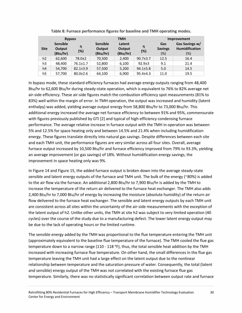
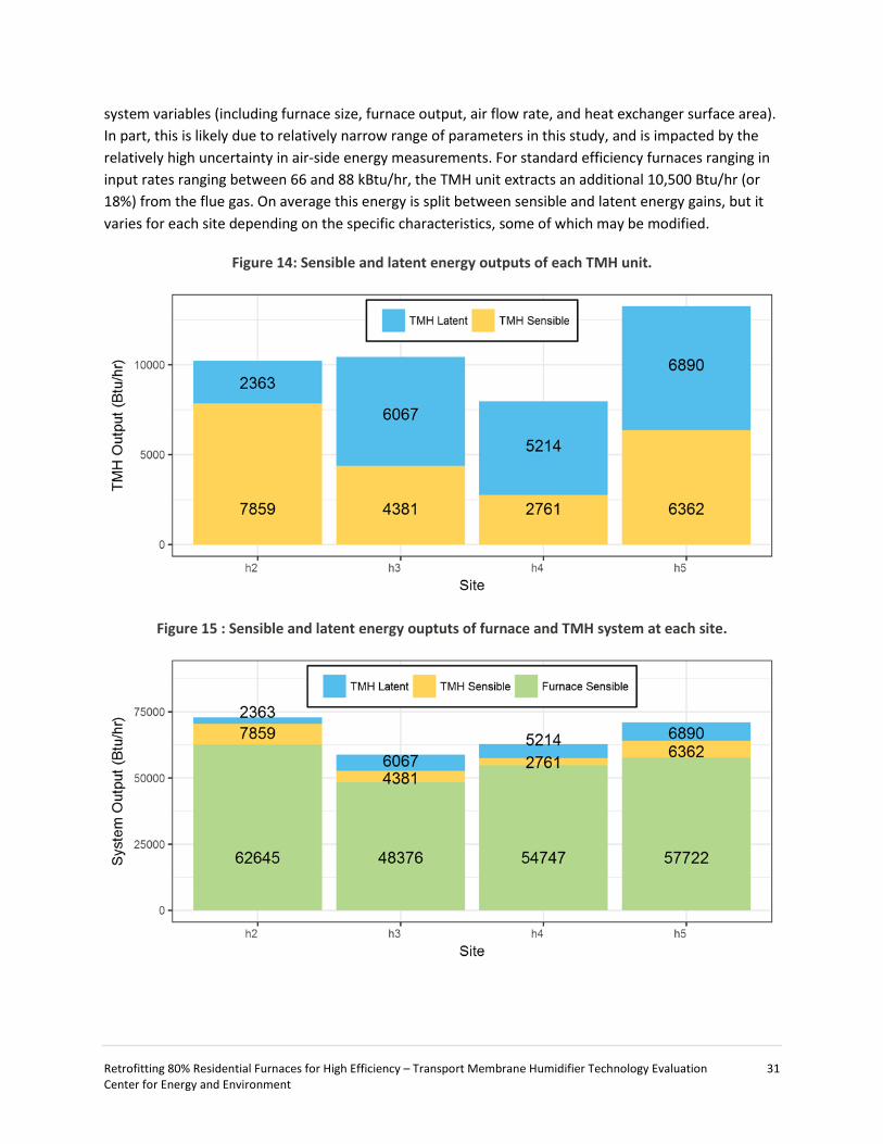
In Figure 14 and Figure 15, the added furnace output is broken down into the average steady-state sensible and latent energy outputs of the furnace and TMH unit. The bulk of the energy (~80%) is added to the air flow via the furnace. An additional 2,800 Btu/hr to 7,900 Btu/hr is added by the TMH to increase the temperature of the return air delivered to the furnace heat exchanger. The TMH also adds 2,400 Btu/hr to 7,000 Btu/hr of energy by increasing the moisture (absolute humidity) of the return air flow delivered to the furnace heat exchanger. The sensible and latent energy outputs by each TMH unit are consistent across all sites within the uncertainty of the air-side measurements with the exception of the latent output of h2. Unlike other units, the TMH at site h2 was subject to very limited operation (40 cycles) over the course of the study due to a manufacturing defect. The lower latent energy output may be due to the lack of operating hours or the limited runtime.
The sensible energy added by the TMH was proportional to the flue temperature entering the TMH unit (approximately equivalent to the baseline flue temperature of the furnace). The TMH cooled the flue gas temperature down to a narrow range (110 - 118 ᵒF), thus, the total sensible heat addition by the TMH increased with increasing furnace flue temperature. On other hand, the small differences in the flue gas temperature leaving the TMH unit had a large effect on the latent output due to the nonlinear relationship between temperature and the saturation pressure of water. Consequently, the total (latent and sensible) energy output of the TMH was not correlated with the existing furnace flue gas temperature. Similarly, there was no statistically significant correlation between output rate and furnace
Retrofitting 80% Residential Furnaces for High Efficiency – Transport Membrane Humidifier Technology Evaluation 31 Center for Energy and Environment
system variables (including furnace size, furnace output, air flow rate, and heat exchanger surface area). In part, this is likely due to relatively narrow range of parameters in this study, and is impacted by the relatively high uncertainty in air-side energy measurements. For standard efficiency furnaces ranging in input rates ranging between 66 and 88 kBtu/hr, the TMH unit extracts an additional 10,500 Btu/hr (or 18%) from the flue gas. On average this energy is split between sensible and latent energy gains, but it varies for each site depending on the specific characteristics, some of which may be modified.
Figure 14: Sensible and latent energy outputs of each TMH unit.
Figure 15 : Sensible and latent energy ouptuts of furnace and TMH system at each site.
Retrofitting 80% Residential Furnaces for High Efficiency – Transport Membrane Humidifier Technology Evaluation 32 Center for Energy and Environment
Humidifier Performance Summary
TMH units transfer some of the moisture from the flue gas into the building return air to increase humidity levels. The rate of moisture transfer depends on the existing humidity level in the house and the furnace runtime. Hence the humidity output is expected to vary throughout the heating season as indoor humidity levels and furnace run time fluctuate.
There are two ways to describe humidifier output — the instantaneous output and the observed output over time. The instantaneous output describes the amount of moisture added during TMH and furnace operation. However, the TMH only adds moisture when the furnace is running due to a call for heat, and real or observed output must be determined by including non-operational periods. One way to describe this observed output is the daily average. Both outputs are summarized in Figure 16 and Table 9.
Figure 16: TMH humidifier outputs (Pints/day) per cycle and day for each site.
Table 9: Humidifier performance summary.
h2 h3 h4 h5 Cycle Output (Pints/day)
25th % 82 137 82 77 Median 114 164 112 106 75th % 128 178 132 137 Max 168 288 209 281
Daily Output (Pints/day) 25th % - 12 9 6 Median - 21 14 13 75th % - 29 16 29 Max - 55 23 30
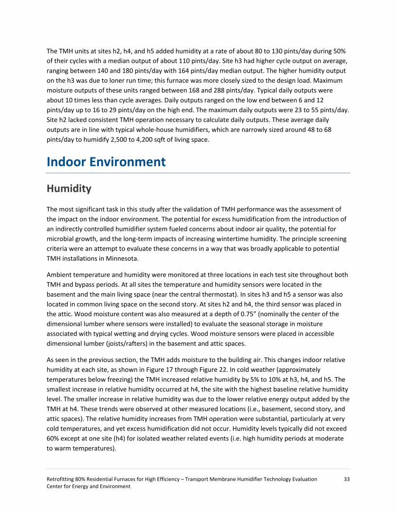
Retrofitting 80% Residential Furnaces for High Efficiency – Transport Membrane Humidifier Technology Evaluation 33 Center for Energy and Environment
The TMH units at sites h2, h4, and h5 added humidity at a rate of about 80 to 130 pints/day during 50% of their cycles with a median output of about 110 pints/day. Site h3 had higher cycle output on average, ranging between 140 and 180 pints/day with 164 pints/day median output. The higher humidity output on the h3 was due to loner run time; this furnace was more closely sized to the design load. Maximum moisture outputs of these units ranged between 168 and 288 pints/day. Typical daily outputs were about 10 times less than cycle averages. Daily outputs ranged on the low end between 6 and 12 pints/day up to 16 to 29 pints/day on the high end. The maximum daily outputs were 23 to 55 pints/day. Site h2 lacked consistent TMH operation necessary to calculate daily outputs. These average daily outputs are in line with typical whole-house humidifiers, which are narrowly sized around 48 to 68 pints/day to humidify 2,500 to 4,200 sqft of living space.
Indoor Environment
Humidity
The most significant task in this study after the validation of TMH performance was the assessment of the impact on the indoor environment. The potential for excess humidification from the introduction of an indirectly controlled humidifier system fueled concerns about indoor air quality, the potential for microbial growth, and the long-term impacts of increasing wintertime humidity. The principle screening criteria were an attempt to evaluate these concerns in a way that was broadly applicable to potential TMH installations in Minnesota.
Ambient temperature and humidity were monitored at three locations in each test site throughout both TMH and bypass periods. At all sites the temperature and humidity sensors were located in the basement and the main living space (near the central thermostat). In sites h3 and h5 a sensor was also located in common living space on the second story. At sites h2 and h4, the third sensor was placed in the attic. Wood moisture content was also measured at a depth of 0.75” (nominally the center of the dimensional lumber where sensors were installed) to evaluate the seasonal storage in moisture associated with typical wetting and drying cycles. Wood moisture sensors were placed in accessible dimensional lumber (joists/rafters) in the basement and attic spaces.
As seen in the previous section, the TMH adds moisture to the building air. This changes indoor relative humidity at each site, as shown in Figure 17 through Figure 22. In cold weather (approximately temperatures below freezing) the TMH increased relative humidity by 5% to 10% at h3, h4, and h5. The smallest increase in relative humidity occurred at h4, the site with the highest baseline relative humidity level. The smaller increase in relative humidity was due to the lower relative energy output added by the TMH at h4. These trends were observed at other measured locations (i.e., basement, second story, and attic spaces). The relative humidity increases from TMH operation were substantial, particularly at very cold temperatures, and yet excess humidification did not occur. Humidity levels typically did not exceed 60% except at one site (h4) for isolated weather related events (i.e. high humidity periods at moderate to warm temperatures).
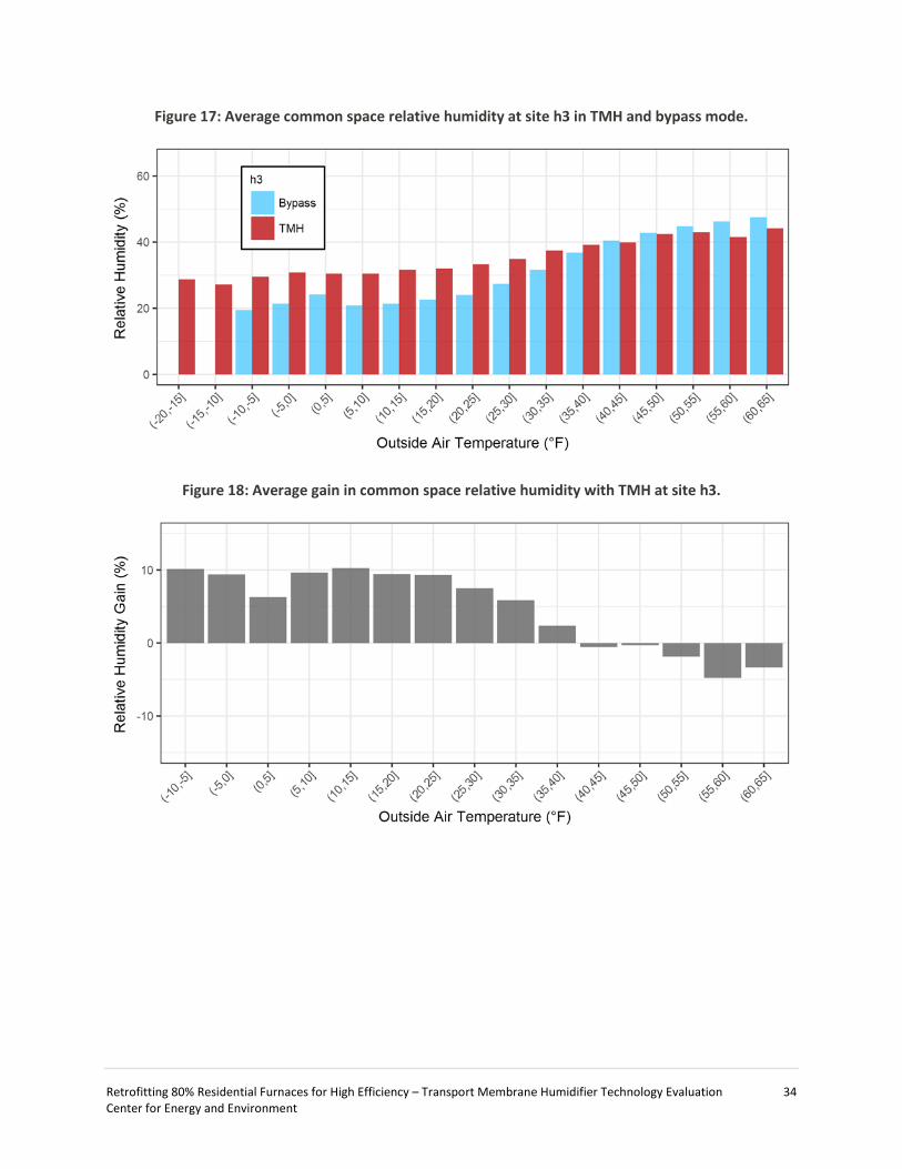
Retrofitting 80% Residential Furnaces for High Efficiency – Transport Membrane Humidifier Technology Evaluation 34 Center for Energy and Environment
Figure 17: Average common space relative humidity at site h3 in TMH and bypass mode.
Figure 18: Average gain in common space relative humidity with TMH at site h3.
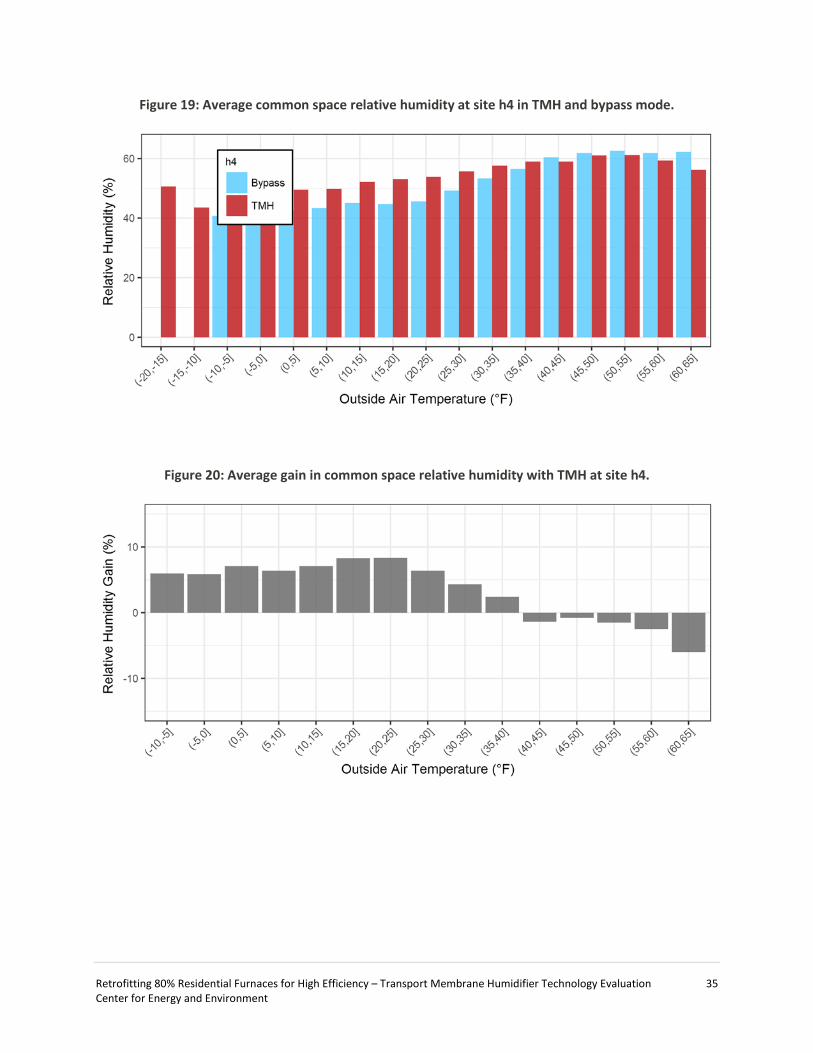
Retrofitting 80% Residential Furnaces for High Efficiency – Transport Membrane Humidifier Technology Evaluation 35 Center for Energy and Environment
Figure 19: Average common space relative humidity at site h4 in TMH and bypass mode.
Figure 20: Average gain in common space relative humidity with TMH at site h4.
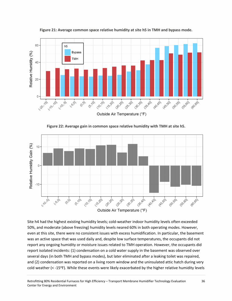
Retrofitting 80% Residential Furnaces for High Efficiency – Transport Membrane Humidifier Technology Evaluation 36 Center for Energy and Environment
Figure 21: Average common space relative humidity at site h5 in TMH and bypass mode.
Figure 22: Average gain in common space relative humidity with TMH at site h5.
Site h4 had the highest existing humidity levels; cold-weather indoor humidity levels often exceeded 50%, and moderate (above freezing) humidity levels neared 60% in both operating modes. However, even at this site, there were no consistent issues with excess humidification. In particular, the basement was an active space that was used daily and, despite low surface temperatures, the occupants did not report any ongoing humidity or moisture issues related to TMH operation. However, the occupants did report isolated incidents: (1) condensation on a cold water supply in the basement was observed over several days (in both TMH and bypass modes), but later eliminated after a leaking toilet was repaired, and (2) condensation was reported on a living room window and the uninsulated attic hatch during very cold weather (< -15ᵒF). While these events were likely exacerbated by the higher relative humidity levels

Retrofitting 80% Residential Furnaces for High Efficiency – Transport Membrane Humidifier Technology Evaluation 37 Center for Energy and Environment
of TMH mode, they were ultimately short lived, inconsequential, and very typical of single-family home performance in very cold weather.
The other notable feature of the relative humidity output as a function of outside air temperature is the existence of a consistent “switchover” temperature where the indoor relative humidity in bypass mode is higher than TMH mode (40ᵒF to 45ᵒF). There are two contributing factors to this observation. The main factor was that outdoor absolute humidity values were higher in bypass mode than TMH mode during these tests, particularly site h5, as shown in Figure 23. This discrepancy was mainly due to the baseline period in December 2016, which was exceptionally warm and humid. Sites h3 and h4 were less affected due to additional baseline data outside this period. This also exposes the challenge of an alternate mode test to control for both differences in multiple variables.
All three cases highlight the diminishing influence of humidification at high temperatures where air exchange with the environment can wet or dry, unlike the universal drying that occurs below freezing temperatures. The second contributing factor is runtime. TMH units were run less at warmer temperatures and therefore their humidity output was less significant compared to both other humidity generation sources and rates of exchange with the environment. In other words, indoor humidity is strongly correlated with outdoor humidity and the moisture output due to low furnace runtime is small in comparison.
Figure 23: Average outside absolute humidity during bypass and TMH periods for site h5.
Moisture Storage
One potential consequence of increased levels of relative humidity during the winter is the interruption of the seasonal drying/wetting cycle of the building. Excessive humidification in the winter may prevent the drying of the structure, which could potentially lead to moisture accumulation that would result in

Retrofitting 80% Residential Furnaces for High Efficiency – Transport Membrane Humidifier Technology Evaluation 38 Center for Energy and Environment
microbial growth or rot, thus compromising the structural integrity of the building or adverse health effects. Wood moisture sensors that monitored the center of dimensional lumber in the houses demonstrate no interruption to the natural building cycle, as shown in Figure 24 through Figure 26. At sites h3 and h5, the seasonal drying cycle is uninterrupted by changes in furnace mode (TMH/bypass). That is to say, the TMH does not increase relative humidity to levels that would drive moisture into the wood during the winter and the material continues to dry during winter months. The attic space at site h4 is an interesting space in that it does not follow the conventional winter drying cycle. Moisture levels within the particular rafter are high enough to raise concerns; however, the TMH is not a driving factor for this seasonal cycle.
Figure 24: Wood moisture equivalent in attic floor joist and basement ceiling joist at site h3.
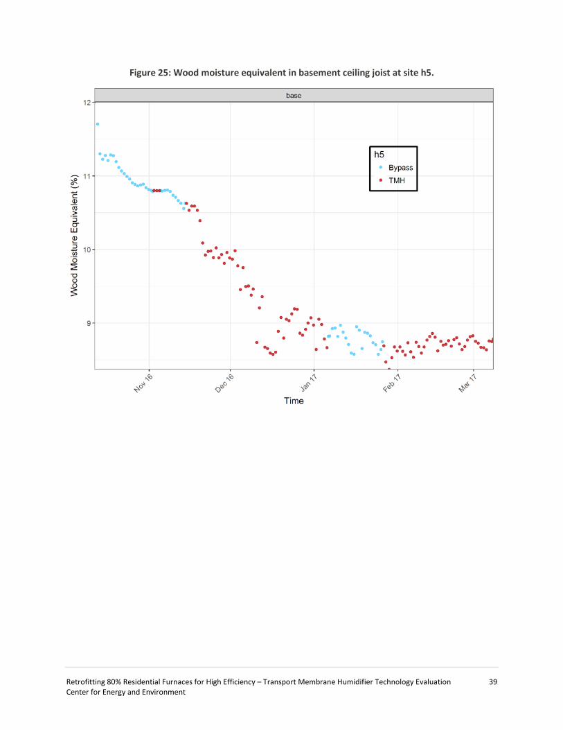
Retrofitting 80% Residential Furnaces for High Efficiency – Transport Membrane Humidifier Technology Evaluation 39 Center for Energy and Environment
Figure 25: Wood moisture equivalent in basement ceiling joist at site h5.

Retrofitting 80% Residential Furnaces for High Efficiency – Transport Membrane Humidifier Technology Evaluation 40 Center for Energy and Environment
Figure 26: Wood moisture equivalent and local relative humidity attic rafter and basement ceiling joist at site h4.
Cost Effectiveness & Payback
Capital Costs
GTI reported capital cost estimates for two different scenarios in a prior research report [2]. Those estimates are reproduced in Table 10 with one change: the membrane tube cost was reduced in this study due to the fewer number of tubes used in the current units compared to the higher capacity GTI reference designs. The costs of production are estimated at $625 in the nominal case and $402 under high volume production. The estimated retail price of a TMH unit ranges between $603 and $938, assuming a 50% markup to handle intermediate costs such as distribution and profits. The upper end of this estimate approaches the wholesale cost of a new 80 kBtu condensing furnace, although with markup and ancillary hardware the capital costs are substantially cheaper for TMH units compared to

Retrofitting 80% Residential Furnaces for High Efficiency – Transport Membrane Humidifier Technology Evaluation 41 Center for Energy and Environment
furnace replacement in all cases. The two biggest drivers of cost are the membrane tubes and the installation labor. Other material and commodity costs are largely fixed in comparison.
Table 10: Capital cost and retail price of TMH units under nominal and high productive volume scenarios.
Direct Production Cost High Volume Case
Nominal Case
Membrane Tubes $150 $200 Tubesheet $30 $40 Adhesive $15 $20 Side plates $7 $10 TMH inlet/out transition $15 $20 ID fan $45 $65 Control-pressure switch $15 $20 Assembly Labor $125 $250
Total Production Cost $402 $625 Retail Price (50% markup) $603 $938
Installation Labor & Material Costs
A well-known, large contractor was recruited to install the TMH units, inspect furnaces, and perform any needed service. The contractor selected one crew of two mechanical technicians and one electrical technician to install all the units. In preparation for the first installation, the contractors were given five pages of instructions. CEE staff were on site to document each installation, clarify the installation procedure, authorize any unexpected requirements, and facilitate communication between participants and the contractor. The four installations were scheduled at the first appointment slot (7:00 am), with the intention that they be completed in a day even in the event of unforeseen installation challenges.
The time spent installing each TMH unit is given in Figure 27. Labor hours were divided into several categories. The critical installation tasks are represented in blue, and these represent a reasonable lower limit for the labor necessary for these four installs. The categories highlighted in red represent the time the contractors were on site, though not necessarily engaged in the TMH installation. The sums of the blue and red categories represent an upper limit for installation labor. These minimum and maximum installation times are given in Table 11. The minimum estimated installation time varied between seven and 11 hours across all sites while the maximum estimated installation time varied between eight and 16 hours. The main difference between these estimates is the coordination time, or the amount of time contractors were waiting to begin work. In most cases it was the early arrival of the electrician who waited until the completion of the mechanical work to begin. Site h4 had insufficient and somewhat dilapidated return ductwork that needed to be repaired and brought up to specification before the TMH unit was installed. This added time may be representative of the additional labor hours necessary to upgrade existing installations that do not meet specification (or possibly current code).
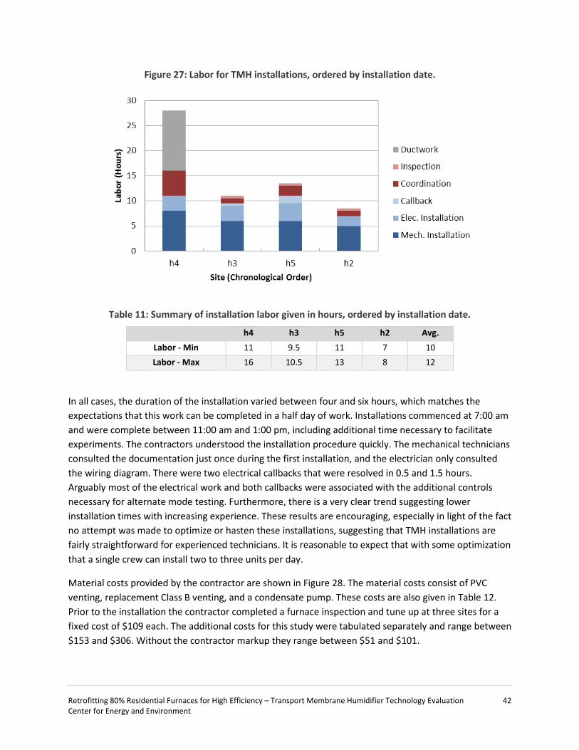
Retrofitting 80% Residential Furnaces for High Efficiency – Transport Membrane Humidifier Technology Evaluation 42 Center for Energy and Environment
Figure 27: Labor for TMH installations, ordered by installation date.
Table 11: Summary of installation labor given in hours, ordered by installation date.
h4 h3 h5 h2 Avg. Labor - Min 11 9.5 11 7 10 Labor - Max 16 10.5 13 8 12
In all cases, the duration of the installation varied between four and six hours, which matches the expectations that this work can be completed in a half day of work. Installations commenced at 7:00 am and were complete between 11:00 am and 1:00 pm, including additional time necessary to facilitate experiments. The contractors understood the installation procedure quickly. The mechanical technicians consulted the documentation just once during the first installation, and the electrician only consulted the wiring diagram. There were two electrical callbacks that were resolved in 0.5 and 1.5 hours. Arguably most of the electrical work and both callbacks were associated with the additional controls necessary for alternate mode testing. Furthermore, there is a very clear trend suggesting lower installation times with increasing experience. These results are encouraging, especially in light of the fact no attempt was made to optimize or hasten these installations, suggesting that TMH installations are fairly straightforward for experienced technicians. It is reasonable to expect that with some optimization that a single crew can install two to three units per day.
Material costs provided by the contractor are shown in Figure 28. The material costs consist of PVC venting, replacement Class B venting, and a condensate pump. These costs are also given in Table 12. Prior to the installation the contractor completed a furnace inspection and tune up at three sites for a fixed cost of $109 each. The additional costs for this study were tabulated separately and range between $153 and $306. Without the contractor markup they range between $51 and $101.
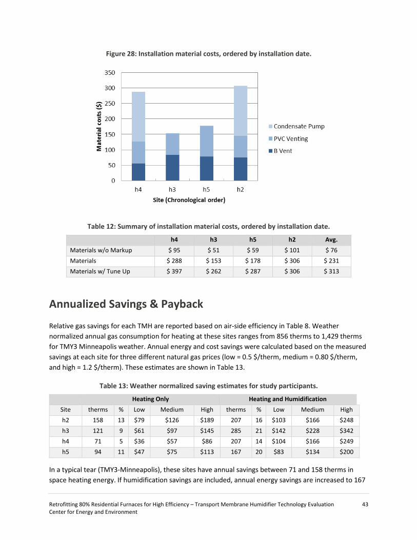
Retrofitting 80% Residential Furnaces for High Efficiency – Transport Membrane Humidifier Technology Evaluation 43 Center for Energy and Environment
Figure 28: Installation material costs, ordered by installation date.
Table 12: Summary of installation material costs, ordered by installation date.
h4 h3 h5 h2 Avg. Materials w/o Markup $ 95 $ 51 $ 59 $ 101 $ 76 Materials $ 288 $ 153 $ 178 $ 306 $ 231 Materials w/ Tune Up $ 397 $ 262 $ 287 $ 306 $ 313
Annualized Savings & Payback
Relative gas savings for each TMH are reported based on air-side efficiency in Table 8. Weather normalized annual gas consumption for heating at these sites ranges from 856 therms to 1,429 therms for TMY3 Minneapolis weather. Annual energy and cost savings were calculated based on the measured savings at each site for three different natural gas prices (low = 0.5 $/therm, medium = 0.80 $/therm, and high = 1.2 $/therm). These estimates are shown in Table 13.
Table 13: Weather normalized saving estimates for study participants.
Heating Only Heating and Humidification Site therms % Low Medium High therms % Low Medium High h2 158 13 $79 $126 $189 207 16 $103 $166 $248 h3 121 9 $61 $97 $145 285 21 $142 $228 $342 h4 71 5 $36 $57 $86 207 14 $104 $166 $249 h5 94 11 $47 $75 $113 167 20 $83 $134 $200
In a typical tear (TMY3-Minneapolis), these sites have annual savings between 71 and 158 therms in space heating energy. If humidification savings are included, annual energy savings are increased to 167

Retrofitting 80% Residential Furnaces for High Efficiency – Transport Membrane Humidifier Technology Evaluation 44 Center for Energy and Environment
therms to 285 therms; however, none of the sites in this study consistently operated humidifiers. Cost savings vary in proportion to the size of the heating load, the heating savings, and the cost of natural gas. For space heating only, annual cost savings are expected range between $36/year and $189/year. When humidification savings are included, the cost savings increase to between $83/year and $342/year.
Cost and energy savings estimates have been combined to create several different scenarios to evaluate the cost-effective potential of TMH technology in Minnesota single-family homes. Low and high gas prices are retained from the energy and cost savings estimates in Table 13. The cost of two fully-loaded installed TMH are explored based on the low and high end of capital and installation costs, and two savings credit scenarios are explored. The first savings credit scenario includes a $200 humidifier credit, assuming the TMH can displace a new whole-house humidifier or several portable humidifiers. The second assumes a nominal $200 energy efficiency rebate for the installation of a TMH. The simple paybacks are given for the low and high fully-loaded TMH costs in Table 14 and Table 15, respectively. The results are color coded on a sliding scale from green to red. Paybacks of less than five years are dark green; paybacks between five and 15 years are yellow/orange, and paybacks greater than 15 years are in red.
Table 14: Simple payback under low and high gas prices and incentive scenarios or low install cost ($1,367).
Heating only Heating and Humidification
Heating and Humidification w/
$200 humidifier credit
Heating and Humidification w/ humidifier credit &
$200 rebate
Site Low High Low High Low High Low High Scenario 1 17.3 7.2 13.2 5.5 11.3 4.7 9.4 3.9
Scenario 2 22.6 9.4 9.6 4.0 8.2 3.4 6.8 2.8
Scenario 3 38.3 16.0 13.2 5.5 11.3 4.7 9.3 3.9
Scenario 4 29.1 12.1 16.4 6.8 14.0 5.8 11.6 4.8
Table 15: Simple payback under low and high gas prices and incentive scenarios for high install cost ($1,904)
Heating only Heating and Humidification
Heating and Humidification w/
$200 humidifier credit
Heating and Humidification w/ humidifier credit &
$200 rebate
Site Low High Low High Low High Low High Scenario 5 24.1 10.1 18.4 7.7 16.5 6.9 14.5 6.1
Scenario 6 31.5 13.1 13.4 5.6 12.0 5.0 10.6 4.4
Scenario 7 53.3 22.2 18.4 7.7 16.4 6.9 14.5 6.0
Scenario 8 40.4 16.9 22.8 9.5 20.4 8.5 18.0 7.5

Retrofitting 80% Residential Furnaces for High Efficiency – Transport Membrane Humidifier Technology Evaluation 45 Center for Energy and Environment
TMH has a unique requirement for payback since they are nominally installed on older furnaces. The lifespan of the TMH is likely limited to the lifetime of the underlying furnace. While standard efficiency furnaces are long-lived devices, a TMH installed on a 10- or 15-year old furnace may only have a five to 15 year lifetime, rather than the full 15 to 30 year where it may otherwise operate. Hence, from a cost-effectiveness perspective, the requirements are more demanding — TMH units must pay back in less than 15 years to be considered cost effective.
Payback periods range dramatically (over a factor of 10), depending on the underlying assumptions. For heating-only savings, only two payback periods are less than 10 years, and these require high gas prices to achieve. Even in the case of high gas prices, there are only few scenarios where a TMH can payback before end of life (less than 15 years), based only on heating savings. Paybacks become acceptable if humidification savings are included. For the two TMH cost scenarios, payback periods are between four and 10 years for all scenarios. Attractive payback periods (under five years) are only really possible by claiming full savings in scenarios with high gas prices as well as some kind of credit or subsidy.
The assumptions here are considered somewhat conservative with respect to TMH costs. One can imagine a set of circumstances where both capital costs and installation costs come down due to economies of scale, lower unit markup, and installation efficiency. Unfortunately even in the case where TMH units cost 30% to 50% less, the underlying trend in cost effectiveness doesn’t change. Both heating and humidification savings as well as medium to high gas prices are required to make TMH units attractive on a cost effective basis. While the math can be shifted by incentives and credits, cost effectiveness is probably not the right framework to justify the mass-deployment of TMH units. Rather, the TMH is an opportunity to provide energy savings at costs that are justified when considering its lifetime.
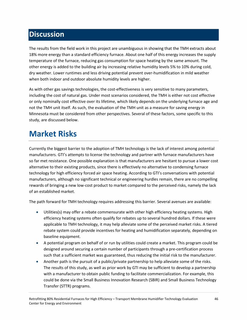
Retrofitting 80% Residential Furnaces for High Efficiency – Transport Membrane Humidifier Technology Evaluation 46 Center for Energy and Environment
Discussion
The results from the field work in this project are unambiguous in showing that the TMH extracts about 18% more energy than a standard efficiency furnace. About one half of this energy increases the supply temperature of the furnace, reducing gas consumption for space heating by the same amount. The other energy is added to the building air by increasing relative humidity levels 5% to 10% during cold, dry weather. Lower runtimes and less driving potential prevent over-humidification in mild weather when both indoor and outdoor absolute humidity levels are higher.
As with other gas savings technologies, the cost-effectiveness is very sensitive to many parameters, including the cost of natural gas. Under most scenarios considered, the TMH is either not cost effective or only nominally cost effective over its lifetime, which likely depends on the underlying furnace age and not the TMH unit itself. As such, the evaluation of the TMH unit as a measure for saving energy in Minnesota must be considered from other perspectives. Several of these factors, some specific to this study, are discussed below.
Market Risks Currently the biggest barrier to the adoption of TMH technology is the lack of interest among potential manufacturers. GTI’s attempts to license the technology and partner with furnace manufacturers have so far met resistance. One possible explanation is that manufacturers are hesitant to pursue a lower cost alternative to their existing products, since there is effectively no alternative to condensing furnace technology for high efficiency forced air space heating. According to GTI’s conversations with potential manufacturers, although no significant technical or engineering hurdles remain, there are no compelling rewards of bringing a new low-cost product to market compared to the perceived risks, namely the lack of an established market.
The path forward for TMH technology requires addressing this barrier. Several avenues are available:
• Utilities(s) may offer a rebate commensurate with other high efficiency heating systems. High efficiency heating systems often qualify for rebates up to several hundred dollars. If these were applicable to TMH technology, it may help alleviate some of the perceived market risks. A tiered rebate system could provide incentives for heating and humidification separately, depending on baseline equipment.
• A potential program on behalf of or run by utilities could create a market. This program could be designed around securing a certain number of participants through a pre-certification process such that a sufficient market was guaranteed, thus reducing the initial risk to the manufacturer.
• Another path is the pursuit of a public/private partnership to help alleviate some of the risks. The results of this study, as well as prior work by GTI may be sufficient to develop a partnership with a manufacturer to obtain public funding to facilitate commercialization. For example, this could be done via the Small Business Innovation Research (SBIR) and Small Business Technology Transfer (STTR) programs.

Retrofitting 80% Residential Furnaces for High Efficiency – Transport Membrane Humidifier Technology Evaluation 47 Center for Energy and Environment
Early Recognition of Energy Savings Over a longer time horizon (i.e. 30-50 years), forced-air residential air space heating may transition completely to high efficiency heating systems and eliminate opportunity for TMH technology. The TMH is a cheaper and faster route to high-efficiency heating compared to condensing furnace upgrades, but the lifetime savings are tied to existing furnace longevity, and in some cases the limited lifetime may prevent cost recovery. The opportunity offered by the TMH is an alternative to furnace replacement that may allow the early recognition of these savings. While the current lack of commercial interest is a major barrier, the case can be made that the opportunity for these savings will remain for some time.
Despite the introduction of high efficiency (condensing) forced air heating systems several decades ago, standard efficiency units still dominate the forced-air furnace install base in Minnesota. Today high efficiency furnaces command a majority of the market (~70%), but this proportion has plateaued and even declined recently. Consequently nearly 900,000 standard efficiency furnaces remain in the state and 15,000 to 25,000 units are still installed annually. The transition to high efficiency heating has stalled somewhat and will likely take decades to complete, which leaves a tremendous amount of potential natural gas savings on the table.
A simple model was created to forecast the number of standard efficiency furnaces in Minnesota under a variety of scenarios. The purpose of testing several scenarios was to estimate the total potential addressable market of the TMH and how it may change over time during the transition to high efficiency heating systems. The parameters and their variations for this calculation are given in Table 16. They are the average furnace lifetime, the furnace replacement rate, and the year a possible 90%+ minimum efficiency standard may come into effect.
Table 16: Model parameters and their range
Parameter Range Average life (yr) 12 – 25 New install rate 38 – 52 % Install rate trend Constant or decline to zero Adoption of 90% efficiency standard (yr) 2020 – 2035
These parameter variations produced a range of forecasts for the number of standard efficiency furnaces remaining in Minnesota over the next several decades, allowing the estimation of the potential addressable market for the TMH over time. The scenarios describing the lowest and highest persistence of standard efficiency furnaces over time are shown in in Figure 29. All modeled scenarios lie within the shaded region. The lower savings bound is created by assuming a 2020 policy-directed transition to high efficiency heating and a standard efficiency install rate of 38% of new units. The upper bound represents a scenario where no high-efficiency policy is established until 2035 and a natural transition occurs at the current replacement rate. As shown in Figure 1, these scenarios suggest hundreds of thousands standard efficiency furnaces will be installed and remain for between 18 to 46 more years. Over that time, these units will cumulatively use between 12 – 105 trillion Btu more than high efficiency furnaces. These scenarios represent a maximum addressable natural gas savings for TMH technology of between

Retrofitting 80% Residential Furnaces for High Efficiency – Transport Membrane Humidifier Technology Evaluation 48 Center for Energy and Environment
7 to 63 trillion Btu. Averaged over these time periods, the opportunity is 0.45 to 1.38 trillion Btu per year or about $2.5 to $7 million per year at today’s gas prices.
Figure 29: Forecast of the number of standard efficiency furnaces remaining in the state under a variety of scenarios
These maximum savings are not achievable due to practical limitations. However, if one assumes that TMH units can be installed at similar rates as standard efficiency furnaces, the potential savings remain very large, about 6% to 20% on average of the annual CIP natural gas savings goal. This analysis suggests that while potential TMH savings diminishes greatly overtime, there remains a very large time horizon (a decade or more) over which current barriers to TMH technology can be overcome to still affect important energy savings and emissions reductions.
Non-Energy Benefits While the humidification may or may not be counted in the energy savings of the TMH unit, the increased humidification is in most cases (i.e. dry houses) a non-energy benefit, albeit one that is difficult to qualify. It is widely recognized that relative humidity levels below 20% are uncomfortable, yet these levels of humidity are common for single-family homes in Minnesota. As seen in this study, the TMH unit increases relative humidity by 5% to 10%, which may alleviate certain occupant sensitivities to very low relative humidity. That said, participants in this study offered no comments about relative humidity levels. Only one comment was made regarding the issue in hindsight. At the conclusion of the study one occupant asked the researchers whether the TMH was responsible for their decision to not use portable dehumidifiers in their bedrooms during midwinter. At best, one might construe this as weak evidence as to humidification benefit of the TMH.

Retrofitting 80% Residential Furnaces for High Efficiency – Transport Membrane Humidifier Technology Evaluation 49 Center for Energy and Environment
Operations
TMH Fouling
TMH units installed in the return drop see unfiltered return air. The fouling from this placement is shown in photographs taken after the removal of each unit. In Figure 30, the surface facing the return air is shown for each unit. All units show some degree of fouling due to impingement by the unfiltered return air, principally dust, pet hair, and tobacco residue. Sites with pets (h2, h3, and h4) show considerably more fouling with that the site without (h5). With the exception of the tobacco residue (h4), the surfaces wipe clean with a damp rag. Absent direct impingement by return air, the remaining 3/4 of TMH surface area show no visible fouling after 163 to 376 days of furnace operation.
Figure 30: TMH fouling at sites (a) h2, (b) h3, (c), h4, and (d) h5
(a) h2
(b) h3
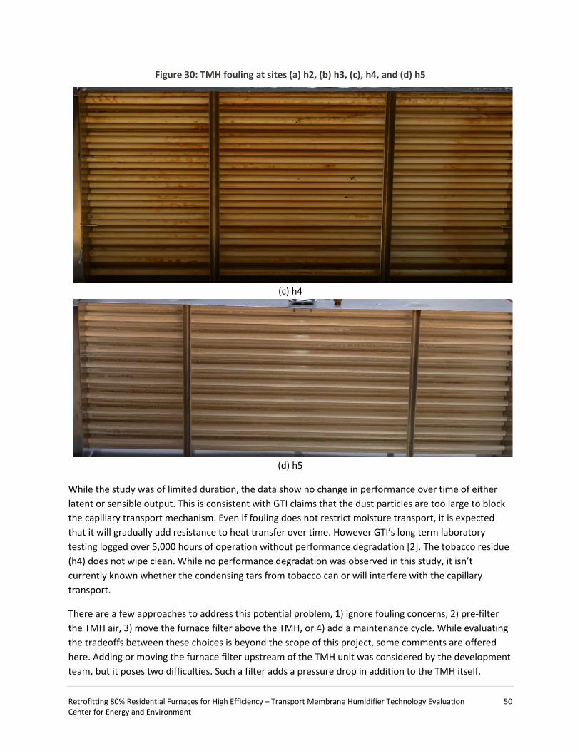
Retrofitting 80% Residential Furnaces for High Efficiency – Transport Membrane Humidifier Technology Evaluation 50 Center for Energy and Environment
Figure 30: TMH fouling at sites (a) h2, (b) h3, (c), h4, and (d) h5
(c) h4
(d) h5
While the study was of limited duration, the data show no change in performance over time of either latent or sensible output. This is consistent with GTI claims that the dust particles are too large to block the capillary transport mechanism. Even if fouling does not restrict moisture transport, it is expected that it will gradually add resistance to heat transfer over time. However GTI’s long term laboratory testing logged over 5,000 hours of operation without performance degradation [2]. The tobacco residue (h4) does not wipe clean. While no performance degradation was observed in this study, it isn’t currently known whether the condensing tars from tobacco can or will interfere with the capillary transport.
There are a few approaches to address this potential problem, 1) ignore fouling concerns, 2) pre-filter the TMH air, 3) move the furnace filter above the TMH, or 4) add a maintenance cycle. While evaluating the tradeoffs between these choices is beyond the scope of this project, some comments are offered here. Adding or moving the furnace filter upstream of the TMH unit was considered by the development team, but it poses two difficulties. Such a filter adds a pressure drop in addition to the TMH itself.

Retrofitting 80% Residential Furnaces for High Efficiency – Transport Membrane Humidifier Technology Evaluation 51 Center for Energy and Environment
Compared to a furnace mounted filter, this new filter pressure drop will be relatively larger because the cross-sectional area of the return drop is much less than a typical return air filter slot. Thus, moving the filter or adding a pre-filter will increase the air-side pressure drop and must be evaluated against airflow requirements. It is also conceivable that the TMH unit be modified to enable cleaning. As mentioned previously, the encountered fouling was easy to remove and with sufficient access to the surfaces facing the return flow. This step could be a periodic maintenance routine or incorporated into regular tune-up activities.
Controls
Two TMH controls were wired into the existing furnace controls as part of this study. In the first circuit the TMH inducer fan was wired in parallel with the existing combustion inducer fan so the fans run together under the main furnace control. A separate auxiliary safety control was also added so that blockage in the flue downstream of the TMH unit prevents the furnace from proving (and subsequently opening the gas valve). This control was a pressure switch wired in series with the existing pressure switch. Additional controls were necessary (and the existing pressure switch preserved) to enable the alternate mode testing of bypass and TMH modes. The added controls were switches that disabled the TMH inducer fan and the TMH pressure switch when the system operated in bypass mode.
In sites h2, h3, and h4, these controls worked as anticipated. Ate site h5 these controls did not function properly in TMH mode. With TMH mode enabled, the furnace control board would periodically read the pressure circuit open or closed in contrast to its actual status. Consequently, the furnace periodically cut out during operation or it did not prove during pre-combustion. Upon failing these events, the furnace fell into a fail-safe mode and attempted to fire on an hourly schedule. It took from one to six attempts (meaning one to six hours) for the furnace to prove and fire, and it required a hard reset to leave fail-safe mode. The random nature of the problem made it difficult to troubleshoot. In some cases it occurred for several cycles in a row, and at other times it didn’t occur for dozens of cycles (i.e. days at a time). About one quarter of the TMH cycles at site h5 were afflicted with this problem. The main consequence was the loss of temperature control. In mild weather this wasn’t noticed by the occupants due to the high thermal inertia of their house. However, at very cold temperatures, these malfunctions would cause the house to cool 4 to 6 degrees below set point (~64ᵒF to 66ᵒF), as the fail-safe schedule prevented the furnace from keeping up with the heating load.
The problem was narrowed down to the operation of two pressure switches in series. While several potential problems were ruled out, a conclusive explanation for this issue was never discovered. The problem was solved by eliminating the secondary pressure switch and verifying the single pressure switch was sufficient to prevent light-off with flue blockage. The leading hypothesis is that the two pressure switches were responding to the vent pressures at two time constants (complicated by the two combustion fans and two vent configurations) and in some cases a close/open circuit was registered early or late. The HVAC electrician who proposed this hypothesis had seen similar issues with the integration of auxiliary venting systems to gas appliances. While the issue was resolved for this study, it does suggest that some furnace controls may be sensitive to alternations in unanticipated ways.

Retrofitting 80% Residential Furnaces for High Efficiency – Transport Membrane Humidifier Technology Evaluation 52 Center for Energy and Environment
Manufacturing Defects
The sealant that was used to seal the entry of the ceramic tubes into the manifold was a pourable silicone. After the poured silicone cured to seal the tubes in place, its perimeter was cut to fit the manifold gasket in place. In two of four units (h2 and h3), this silicone was cut too close to some tubes, which effectively created pinhole peaks. This is an easy issue to fix in manufacturing, but it does give some information about potential TMH failure modes.
In both units, these pinhole leaks from the cut silicone appeared on three tubes at their interface with the exhaust manifold, as shown in Figure 31a. On the flue gas side, the air temperature is about ~110ᵒF and the gases are saturated (~100 %RH). Flue gas condensation on the inside of the exhaust manifold is likely the source of a very small, but consistent source of condensed water. At h3 this condensation was not evident to the participants or researchers during the study. Tear down of the unit at the end of the study revealed that this condensation collected in the slip and drive connection a few inches below the tube array (Figure 31b, Figure 31c).
At site h2, this condensation didn’t collect in the slip and drive, but instead ran down a corner of the return drop and leaked out onto the floor below the furnace. Several attempts were made to identify the source of the condensation before a borescope was inserted into the unit during a TMH cycle. The borescope clearly showed the slow growth of water droplets on two of the tubes at the pinhole leak (Figure 32a). At some point gravity overwhelmed the surface tension of the droplet and it would break off and run down the inside of the return drop (Figure 32b). The first droplets wetted a path for all droplets to follow down to the final slip and drive connector on the return drop where it leaked out onto the floor. The amounts of condensate were small (a few drops per minute), but after several hours of operation it did result in tens of millimeters of condensate on the floor. The participant was uncomfortable with the condensation so this TMH operation was limited to validate performance only.

Retrofitting 80% Residential Furnaces for High Efficiency – Transport Membrane Humidifier Technology Evaluation 53 Center for Energy and Environment
Figure 31: TMH leaks on unit h3 (a) at the silicone manifold on the flue gas side (b) condensate leakage on the return air side, and (c) condensate leakage into the slip and drive joint
(a)
(b)
(c)

Retrofitting 80% Residential Furnaces for High Efficiency – Transport Membrane Humidifier Technology Evaluation 54 Center for Energy and Environment
Figure 32: TMH leaks in unit h2 (a) the accumulation of condensation droplets at the pinholes (air-side) and (b) the condensate staining left behind by falling droplets
(a)
(b)
Project Barriers — Code Compliance TMH units were installed in two jurisdictions with very different permitting and code compliance paths. These two processes are summarized below such that they may inform future attempts to install unlisted devices through a conventional building permitting process.
Code compliance was complicated in this study because TMH units were not certified by a safety testing organization (i.e. Underwriters Laboratories). In one jurisdiction, the code official outlined some added requirements to obtain a temporary permit for the study. The research team provided design documentation about the TMH device and laboratory testing documentation from GTI confirming that manufactured units operated within specification. Researchers agreed to conduct the same tests on the installed unit to validate operating specification in the field. Meeting these requirements, a permit was issued to install the TMH for two operating seasons.
Compliance in the other jurisdiction proved more difficult. The code official initially requested a technical report and professional opinion by a certified professional engineer that the TMH devices complied with the intent of the Minnesota Mechanical and Fuel Gas Code (1346) Minnesota Rule 1300.0100 Subp. 14. The report specifically addressed: 1) the life safety of occupants, 2) firefighter safety, 3) property protection, 4) continuity of operations, and 5) safeguarding of the environment. The technical opinion was submitted alongside design documentation, laboratory testing results, installation instruction, and wiring and P&ID diagrams. The report is included as Appendix C. The code official also requested documentation from furnace manufacturers that the TMH unit would not interfere with the furnace warranty. All furnaces in this jurisdiction were already out of warranty and an insurance policy was in place to replace or repair any issues in equipment or sites that arose from the study.
The building official rejected the permit request, deeming the technical opinion and material insufficient to overcome his concerns. The reason for the rejection was a strong discomfort with installing unlisted
Retrofitting 80% Residential Furnaces for High Efficiency – Transport Membrane Humidifier Technology Evaluation 55 Center for Energy and Environment
devices and experimenting on residential furnaces. A path toward compliance was identified in negotiations; TMH devices would be permitted for installation if they were field certified by Underwriters Laboratories (UL).
The scope of the UL field investigation was negotiated between the research team, the building official, and the UL project manager. With the agreement and work scope in place, one unit was permitted, installed, and tested by UL. The first installation passed the UL inspection and was field certified without any modification. After the first installation, an agreement was reached with the code official that subsequent temporary field installations did not require UL field certification if installation and post-installation testing mirrored the UL field certification procedure.
Ultimately, concerns by code officials boiled down to the use of an uncertified device that operated on flue gases and modified residential furnaces, and the fact that there was no third party to deem these devices safe. Individual city inspectors who signed off on the installations didn’t express any safety or code concerns beyond those evidently considered by a certification organization. As shown above, officials’ differences of opinion on code may result in different paths to code compliance. Addressing these concerns adds additional time, energy, and costs that should be accounted for in similar projects. In this case, it caused a one year delay in installations and about $6,000 of testing costs in addition to added labor for the development of the added documentation, testing, and work scope.

Retrofitting 80% Residential Furnaces for High Efficiency – Transport Membrane Humidifier Technology Evaluation 56 Center for Energy and Environment
Conclusions & Recommendations
This study found that the TMH technology improved the furnace system efficiency while markedly improving indoor humidity levels during cold, dry weather. For standard efficiency furnaces ranging in input rates ranging between 66 and 88 kBtu/hr, the TMH unit extracts an additional 10,500 Btu/hr (or 18%) from the flue gas. On average this energy is split between sensible and latent energy gains, but it varies for each site depending on the specific characteristics. This translates directly into decreased natural gas consumption for space heating by an average of 9% compared to baseline furnace operation. An additional 9% of gas savings are achieved, for a total of 18% natural gas savings, when the humidity output of the TMH displaces conventional humidification equipment. The energy savings from humidification requires that the TMH displace existing humidifiers, otherwise the improved indoor humidity level remains a non-energy benefit.
This study included sites that had indoor humidity levels ranging from less than 20% to over 60%. On average, the TMH increased indoor humidity levels between 5% and 10% below outside air temperatures of 32ᵒF. Above 32ᵒF, the TMH had a marginal effect on indoor humidity, often resulting in lower humidity than baseline conditions by between 0% and 5%. As a humidifier, the TMH output is similar to other whole-house furnace mounted humidifier systems. While capable of very high instantaneous output (250-300 pints/day), typical outputs are 15 to 30 pints/day. Excess or runaway humidification was not observed, and wood moisture monitoring showed that the increased levels of relative humidity were insufficient to interrupt the natural winter drying cycle of the participant homes.
Capital and installation costs were estimated in this project to produce total installed cost estimates that range between $1,367 and $1,904. These costs are about 60% less than a high-efficiency furnace upgrade (NREL, 2017). Several savings and payback scenarios were modeled resulting in payback periods that range between about 2.8 years and 53 years. Payback is most sensitive several factors: 1) space heating load, 2) inclusion of humidification savings, and 3) potential incentives. The nominal savings scenarios produce payback periods in the range of 7 to 15, years indicating that TMH units are cost effective over their lifetime at today’s gas prices. The TMH remains a compelling alternative compared to a furnace replacement, especially for late-model furnaces and those units with a decade or more of remaining lifetime.
The TMH is a viable technology for achieving large natural gas savings for space heating in single family homes and will likely remain so for some time as it will take decades to erode today’s large standard efficiency market share. It is the only viable alternative to a condensing furnace upgrade and it is the cheaper option, particularly for the vast number of standard efficiency furnaces that will remain operational over the coming decades. Still, the TMH is a pre-commercial technology which has not yet been taken up by a manufacturer for commercialization, and this current status remains the major barrier to adoption. Even under a fast transition to high-efficiency heating in the state, there remains a decade or more over which these barriers may be resolved and the TMH introduced for consequential energy savings and emissions reductions.

Retrofitting 80% Residential Furnaces for High Efficiency – Transport Membrane Humidifier Technology Evaluation 57 Center for Energy and Environment
CIP Recommendations
• The major concern expressed by potential manufacturers is the lack of a market for the device. Overcoming this barrier through incentives or installation guarantees to kick start TMH commercialization should be the primary focus of any potential CIP programming. Potential options include:
– Direct rebate offerings that are commensurate with other high efficiency heating system upgrades. High efficiency heating systems often qualify for rebates up to several hundred dollars. Similar equipment installation rebates, promised prior to commercialization, may help alleviate some of the perceived market risks. The rebate structure should be tiered to account for those systems with space heating energy savings as well as humidification savings.
– A potential program, even a pilot program of sufficient size, could help kick-start a market. A program could be designed around securing a certain number of participants through a pre-certification process guaranteeing a sufficient quantity of TMH sales to a potential manufacturer, thus reducing the initial risk of commercialization.
– Lastly, the pursuit of a public/private partnership may sufficiently alleviate the risk of commercialization. The results of this study as well as prior work by GTI, may be sufficient to develop a partnership with a manufacturer to obtain public funding that facilitate commercialization. For example via the Small Business Innovation Research (SBIR) and Small Business Technology Transfer (STTR) programs.
Retrofitting 80% Residential Furnaces for High Efficiency – Transport Membrane Humidifier Technology Evaluation 58 Center for Energy and Environment
References
[1] Wang, D, Bao A, and Liss W. (2012). “An Innovative Technology Development for Building Humidification and Energy Efficiency.” ASME. ASME International Mechanical Engineering Congress and Exposition, V10: Emerging Technologies and Topics; Public Policy. pp: 117-124. doi:10.1115/IMECE2012-86301.
[2] Wang, D and Bao, A, (2012)“Field Trials of the Transport Membrane Humidifier: Final Report.” Technical Report. Gas Technology Institute”
[3] Wang, D, Bao, A, and Liss, W. (2012). “Development of high efficiency home heating and humidification technology.” ASHRAE Transactions. V118. pp: 523-530.
[4] Wang, D, Scott, S, Bao, A, and Liss, W. (2012). “Field trials of a waterless home heating and humidification technology.” ASHRAE Transactions. V118. Pp: 42-49.
[5] Center for Energy and Environment, (2017). “Home Energy Squad Public Dataset compiled for Department of Commerce, Division of Energy Resources.
[6] U.S. Energy Information Administration,(2017) 2015 Residential Energy Consumption Survey Microdata.
[7] United States Census Bureau, (2012), 2010 Census Data.
[8] Center for Energy and Environment, (2018). “Minnesota Potential Study.” Technical Report for Department of Commerce, Division of Energy Resources. (To be completed & published 2018)
[9] Wilcox, S. and W. Marion. 2008. User's Manual for TMY3 Data Sets, NREL/TP-581-43156. April 2008. Golden, Colorado: National Renewable Energy Laboratory.

Retrofitting 80% Residential Furnaces for High Efficiency – Transport Membrane Humidifier Technology Evaluation Center for Energy and Environment 59
Appendix A: TMH Design Documentation
The TMH design drawings for unit h3 are included for reference as Figure 33 through Figure 39. The full set of these drawings were required for the UL Field certification. TMH are differentiated from each other by outside dimensions to accommodate the return drop) and the number and configuration of membrane tubes.
Figure 33: Inlet/outlet manifold and tube layout for TMH h3
Figure 34: Inlet chamber for TMH h3

Appendix A - TMH Design Documentation
Retrofitting 80% Residential Furnaces for High Efficiency – Transport Membrane Humidifier Technology Evaluation 60 Center for Energy and Environment
Figure 35: Outlet chamber for TMH h3
Figure 36: Reinforcement bracket for TMH h3
Figure 37: Outlet reducer for TMH h3
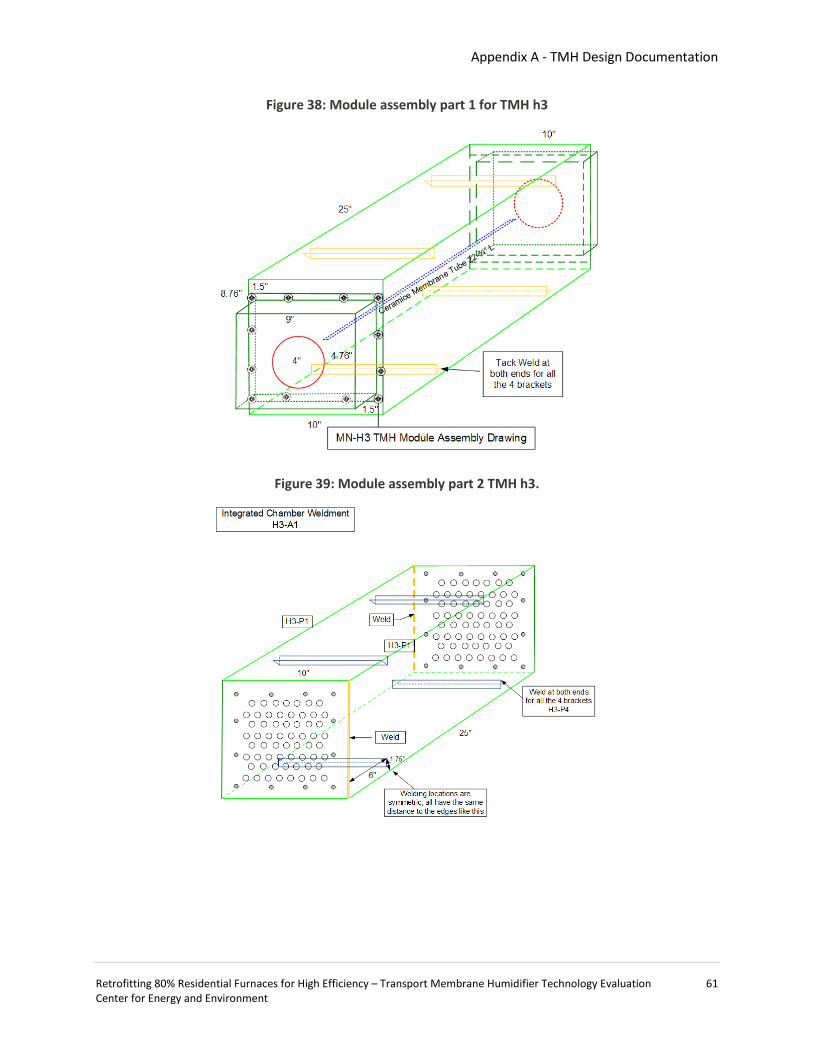
Appendix A - TMH Design Documentation
Retrofitting 80% Residential Furnaces for High Efficiency – Transport Membrane Humidifier Technology Evaluation 61 Center for Energy and Environment
Figure 38: Module assembly part 1 for TMH h3
Figure 39: Module assembly part 2 TMH h3.

Appendix A - TMH Design Documentation
Retrofitting 80% Residential Furnaces for High Efficiency – Transport Membrane Humidifier Technology Evaluation 62 Center for Energy and Environment
Figure 40: Wiring diagram to enable TMH and alternate mode testing controls
Retrofitting 80% Residential Furnaces for High Efficiency – Transport Membrane Humidifier Technology Evaluation Center for Energy and Environment 63
Appendix B: TMH Installation & Startup Instructions
Transport Membrane Humidifier (TMH) Installation and Startup Instructions
Product Description: The TMH heat recovery and humidification system is a pre-assembled package, which includes the TMH unit with an attached and prewired ID fan, a manual switch for ID fan control, a pressure switch safety interlock, and a manual bypass switch as a safety control feature. For field testing and monitoring purposes, a data acquisition box with temperature and humidity instrumentation has been pre-wired and provided. The main component of the TMH unit is an array of ceramic membrane tubes, which allow both heat and moisture from the furnace flue gas to be transferred to the furnace return air, while simultaneously blocking hazardous gas components (CO2, CO, NOX, etc.) from entering the return air stream. A secondary component is an inline inducer fan to depressurize the vent between the TMH and the furnace and to push the flue gas out of a new, sealed exhaust. The TMH unit was designed to be installed into the furnace return air ductwork using conventional sheet metal connectors (slip and drive cleat). Each unit was fabricated with dimensions that match the return air duct work such that it is installed as any other ductwork component.
The attachment to the existing duct work and furnace vent are detailed in a P&ID in Figure 1. The detailed wiring diagram in Figure 2 outlines the electrical connections to the furnace power, control loop and data acquisition box.
Expected installation time: 8 person-hours.
Shipping and Packing List:
1. (1) Transport membrane humidifier unit with preinstalled ID fan, manual bypass switch, and pressure switch
2. (1) 4” Type B Tee vent pipe
3. (2) 4” flue gas bypass dampers
4. Condensate tubing suitable for Category IV vent condensate drain and TMH condensate drain.
Installation Instructions
1. Shutdown and de-energize furnace per furnace manufacturer’s instructions. 2. Remove the TMH unit from the shipping box, and measure its height. Cut out a section of the
return-drop ductwork of equivalent height at a location 1 to 2 feet above the furnace exhaust vent, ensuring a sufficient (1 foot) vertical rise from the furnace exhaust to the TMH inlet.
3. Substitute the TMH for the cut out section of duct work. S-cleats (1 in. width) (Figure 3) should be used to attach the TMH to the existing duct work for a rigid connection. Depending on the existing level of support for the return drop, additional duct hangers may be added to the return drop to support the added weight of the TMH.
4. Seal the transverse joints using aluminum foil tape to prevent any unnecessary air leakage . This completes the TMH air side connection.

Appendix B – TMH Installation & Startup Instructions
Retrofitting 80% Residential Furnaces for High Efficiency – Transport Membrane Humidifier Technology Evaluation 64 Center for Energy and Environment
5. Connect the furnace flue vent to the TMH flue gas inlet with the supplied Tee and two dampers to allow the furnace flue gas to either pass through the TMH unit or directly bypass the TMH and pass through the existing flue stack by adjusting the two dampers. Make connections using standard 4” Type-B double steel wall pipe. Figure 4 shows an example installation with the two dampers. Other damper arrangements are acceptable as long as the dampers open/close horizontally (as shown). Label dampers as “TMH Inlet” and “TMH Bypass.”
6. Site an exterior side-wall vent termination location for the new 2” sealed PVC category IV vent pipe. Measure the total length of the required pipe run and tally the number and type of pipe fittings (90° and 45°) necessary to reach the TMH outlet. Multiply the number of 90° by 5 feet and the number of 45° fittings by 2.5 feet to get the effective pipe length of the added fittings. Add these effective lengths to the total measured length to get the total effective vent pipe length. Verify that this length is less than 60 feet.
7. Install category IV vent components according to specifications outlined in ASTM D 2855. Ensure vent slopes back to TMH at ¼” per 1 foot length. Connect the TMH flue gas outlet to the new 2” sealed PVC category IV vent pipe. Ref: IRC Ch24 (Fuel Gas) G2427 (503) Venting of appliances.
8. The condensate drain and trap should be downstream of the TMH ID fan, an example is shown in Figure 5 in PVC pipe. The TMH outlet chamber also has an internal drain port (upstream of the TMH ID fan) at its bottom. Connect a ¼” plastic tubing connected to the compression fitting to serve as the condensate drain and route it to the house drainage, also shown in Figure 5. A condensate trap is not needed for this second drain connection, since the TMH flue gas outlet chamber is under slightly negative pressure, so flue gas will not leak out. Condensate may occur during TMH cold startup and during normal operations, but a minimal amount of condensate is expected. This completes the TMH unit flue gas side connection.
9. The TMH ID fan (115V, 1/30 HP) will be powered and controlled by the furnace. The TMH ID fan will be connected to the furnace internal ID fan power supply with a manual switch. This will allow the TMH ID fan to be ON when the furnace is ON, and OFF when the furnace is OFF. The TMH ID fan can be manually turned off when the furnace is running in TMH bypass mode. The TMH ID fan and the manual switch have already been prewired according to the provided wiring diagram. To complete the setup, connect the two available leading wires from the TMH unit to the furnace ID fan power supply according to the provided wiring diagram (Figure 2) and the existing furnace wiring schematic.
10. The pressure switch connected to the TMH flue gas outlet chamber (Figure 6) will remove furnace power if a positive pressure is detected. The pressure switch wire leads are labeled for connecting to the furnace in the field according to the provided wiring diagram. The pressure switch wiring is to be connected to the furnace control loop in series with the furnace internal pressure switch, so either of the switches will independently shutdown the furnace if triggered. The additional pressure switch will not affect the furnace internal pressure switch function. Figure 7 shows the pressure switch and TMH ID fan power supply connections. This completes the TMH control connection.
Operating instructions Operation in TMH mode:
1. Shutdown the furnace. 2. Open the TMH inlet flue gas damper, and close the bypass damper.

Appendix B – TMH Installation & Startup Instructions
Retrofitting 80% Residential Furnaces for High Efficiency – Transport Membrane Humidifier Technology Evaluation 65 Center for Energy and Environment
3. Turn the TMH ID fan manual switch to ON and the TMH pressure switch bypass switch to OFF positions (both switches will be in UP position). (Figure 8)
4. Turn on the furnace. The furnace will now operate in TMH mode, and will start or shutdown normally based on the home thermostat signal.
Operation in TMH bypass mode: this mode is only needed when a malfunction occurs with the TMH unit or for testing purposes.
1. Shutdown the furnace. 2. Close the TMH inlet flue gas damper and open the bypass damper. 3. Turn the ID fan manual switch to OFF position and the TMH pressure switch bypass switch to
ON positions (both switches will be in DOWN position). (Figure 9) 4. Turn on the furnace. The furnace will now operate in TMH bypass mode. The furnace will start
and shutdown normally based on the home thermostat signal. All manual switch positions are clearly marked on the switch box.

Appendix B – TMH Installation & Startup Instructions
Retrofitting 80% Residential Furnaces for High Efficiency – Transport Membrane Humidifier Technology Evaluation 66 Center for Energy and Environment
Figure 41: TMH Piping and Instrumentation Diagram
Figure 42: Wiring Diagram for TMH Installation
IDM
TMH-IDM
PS
TMH-PS Other Switches
Wiring Diagram for TMH InstallationLegend: IDM, furnace existing ID fan motor; PS, furnace existing pressure switch; TMH-
IDM, TMH ID fan motor; TMH-PS, TMH pressure switch; MS, manual switch
MS
MSNew for TMH
Control
NC
NO
To Data logger DI-A for furnace ON time
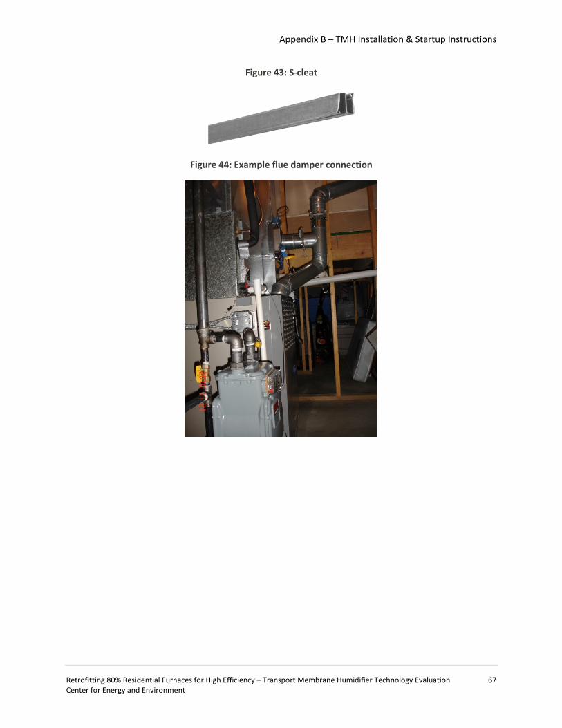
Appendix B – TMH Installation & Startup Instructions
Retrofitting 80% Residential Furnaces for High Efficiency – Transport Membrane Humidifier Technology Evaluation 67 Center for Energy and Environment
Figure 43: S-cleat
Figure 44: Example flue damper connection
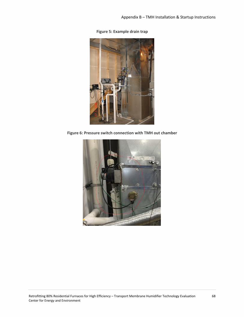
Appendix B – TMH Installation & Startup Instructions
Retrofitting 80% Residential Furnaces for High Efficiency – Transport Membrane Humidifier Technology Evaluation 68 Center for Energy and Environment
Figure 5: Example drain trap
Figure 6: Pressure switch connection with TMH out chamber

Appendix B – TMH Installation & Startup Instructions
Retrofitting 80% Residential Furnaces for High Efficiency – Transport Membrane Humidifier Technology Evaluation 69 Center for Energy and Environment
Figure 7: Pressure switch and TMH ID fan power supply connections
Figure 8: Switches in (a) TMH mode and (b) bypass mode (baseline)
(a)
(b)

Retrofitting 80% Residential Furnaces for High Efficiency – Transport Membrane Humidifier Technology Evaluation Center for Energy and Environment 70
Appendix C: Technical Report and Opinion
Technical Report and Opinion for Transport Membrane Humidifier Residential Installation The report herein shall constitute a technical opinion and report prepared by and bearing the stamp of a Minnesota-licensed Professional Engineer, as requested XXXXXXXXX on 9/18/2015 for consideration of permitting the installation of (4) Transport Membrane Humidifier units (TMH) in single-family residences in XXXXXXXXX as part of a Minnesota Department of Commerce – Division of Energy Resources CARD pilot study #85907. This document evaluates the TMH unit and installation procedure for evidence of compliance with the intent of the Minnesota Mechanical and Fuel Gas Code (1346) Chapter 8: Chimney’s and Vents according to Minnesota Rule 1300.0100 Subp. 14 (ATTACHMENT A). The report specifically addresses as outlined in Supb. 14,
(1) life safety of occupants; (2) firefighter safety; (3) property protection; (4) continuity of operations; and (5) safeguarding of the environment.
It is my professional opinion that the design and the installation of the transport membrane humidifier as described are consistent with the intent of Minnesota Mechanical and Fuel Gas Code (1346). AMENDED CONTENT Two TMH installations have taken place in Minnesota; one currently operating within specification since October 2015. More recently a second installation was completed in July 2016 and subject to an independent field evaluation by Underwriters Laboratories (UL) at the request of the XXXXXXXXX. No corrective actions or evaluation discrepancies were discovered by UL and the installation received UL Field Certification. The field evaluation report is given as ATTACHMENT E. That field evaluation corroborated extensive laboratory testing conducted by the Gas Technology Institute (product developer) and field measurements conducted by Center for Energy and Environment (CEE). Given that the remaining two installations are laboratory tested and field tested according to the same methodology and instrumentation, Center for Energy and Environment feels that the additional steps and costs associated with a third testing agency are unnecessary.
Dave Bohac, P.E. License # 23388 10/1/2015
212 3rd Avenue North, Suite 560 Minneapolis, MN 55401 www.mncee.org main 612.335.5858 fax 612.335.5888
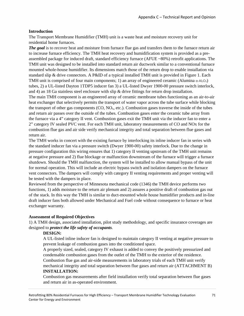
Appendix C – Technical Report and Opinion
Retrofitting 80% Residential Furnaces for High Efficiency – Transport Membrane Humidifier Technology Evaluation 71 Center for Energy and Environment
Introduction The Transport Membrane Humidifier (TMH) unit is a waste heat and moisture recovery unit for residential home furnaces. The goal is to recover heat and moisture from furnace flue gas and transfers them to the furnace return air to increase furnace efficiency. The TMH heat recovery and humidification system is provided as a pre-assembled package for induced draft, standard efficiency furnace (AFUE ~80%) retrofit applications. The TMH unit was designed to be installed into standard return air ductwork similar to a conventional furnace mounted whole-house humidifier. Its dimensions match those of the return drop to enable installation via standard slip & drive connectors. A P&ID of a typical installed TMH unit is provided in Figure 1. Each TMH unit is comprised of four main components; 1) an array of engineered ceramic (Alumina α-Al2O3) tubes, 2) a UL-listed Dayton 1TDP5 inducer fan 3) a UL-listed Dwyer 1900-00 pressure switch interlock, and 4) an 18 Ga stainless steel enclosure with slip & drive fittings for return drop installation. The main TMH component is an engineered array of ceramic membrane tubes functioning as an air-to-air heat exchanger that selectively permits the transport of water vapor across the tube surface while blocking the transport of other gas components (CO, NOx, etc.). Combustion gases traverse the inside of the tubes and return air passes over the outside of the tubes. Combustion gases enter the ceramic tube array from the furnace via a 4” category II vent. Combustion gases exit the TMH unit via the inducer fan to enter a 2” category IV sealed PVC vent. For each TMH unit, laboratory measurements of CO and NOx for the combustion flue gas and air side verify mechanical integrity and total separation between flue gases and return air. The TMH works in concert with the existing furnace by interlocking its inline inducer fan in series with the standard inducer fan via a pressure switch (Dwyer 1900-00) safety interlock. Due to the change in pressure configuration this wiring ensures that 1) category II venting upstream of the TMH unit remains at negative pressure and 2) flue blockage or malfunction downstream of the furnace will trigger a furnace shutdown. Should the TMH malfunction, the system will be installed to allow manual bypass of the unit for normal operation. This will include an electric bypass switch and isolation dampers on the furnace vent connectors. The dampers will comply with category II venting requirements and proper venting will be tested with the dampers in place. Reviewed from the perspective of Minnesota mechanical code (1346) the TMH device performs two functions, 1) adds moisture to the return air plenum and 2) assures a positive draft of combustion gas out of the stack. In this way the TMH is similar to duct-mounted whole house humidifier products and in-line draft inducer fans both allowed under Mechanical and Fuel code without consequence to furnace or heat exchanger warranty. Assessment of Required Objectives 1) A TMH design, associated installation, pilot study methodology, and specific insurance coverages are designed to protect the life safety of occupants.
DESIGN: A UL-listed inline inducer fan is designed to maintain category II venting at negative pressure to prevent leakage of combustion gases into the conditioned space. A properly sized, sealed, category IV exhaust is added to convey the positively pressurized and condensable combustion gases from the outlet of the TMH to the exterior of the residence. Combustion flue gas and air-side measurements in laboratory trials of each TMH unit verify mechanical integrity and total separation between flue gases and return air (ATTACHMENT B) INSTALLATION: Combustion gas measurements after field installation verify total separation between flue gases and return air in as-operated environment.

Appendix C – Technical Report and Opinion
Retrofitting 80% Residential Furnaces for High Efficiency – Transport Membrane Humidifier Technology Evaluation 72 Center for Energy and Environment
Correct operation of existing household carbon monoxide detectors is verified. Install CO detector to directly monitor the carbon monoxide concentration of the return air exiting the TMH and alert of any combustion gas leakage inside the TMH (e.g. a cracked heat exchanger). Long term temperature, humidity, and wood moisture sensors monitor and identify excessive humidity conditions that may support biological growth. INSURANCE COVERAGE: An insurance policy specific to each TMH unit protects home owner from loss of life or property from defects in manufacturing or installation errors (ATTACHMENT D)
2) TMH and associated installation materials and connections do not impact Firefighter safety DESIGN: The TMH is comprised of non-combustible materials (ceramic, stainless steel, and high temperature silicone). The TMH unit has no connections to gas pipes. The TMH will be fully de-energized following a residential furnace lock out procedure.
3) The TMH, pilot study methodology, and specific insurance coverage are designed to afford property protection to participating home owners.
DESIGN: TMH moisture output is consistent with indoor air quality goals of maintaining comfortable indoor temperature and humidity.
MOISTURE OUTPUT (Performance Criteria #1): Published measurements demonstrate a TMH unit adds moisture at a rate of 0.2 GPH for cold, dry conditions from a standard efficiency furnace with 90,000 BTU/hr input rate, (Wang, 2012). Lower input rates furnaces in this study (66,000 to 88,000 BTU/hr) are designed to have moisture outputs of 0.15 to 0.19 GPH. These values are consistent with the laboratory test results (ATTACHMENT B). In comparison this moisture output is considerably less than comparable duct-mounted whole house humidifiers with capacities ranging from 0.5 to 0.75 GPH of moisture into return air (Aprilaire 500). TMH moisture output is driven by a vapor pressure gradient between the return air and the flue gas. At high levels of indoor humidity this gradient is reduced and moisture transport slows. The moisture output of the TMH is self-limiting. HEAT OUTPUT (Performance Criteria #2): TMH units have demonstrated 12% to 14% net efficiency gains on residential standard efficiency furnaces with input rates ranging from 90,000 to 110,000 BTU/hr (Wang, 2012). Lower input rates of furnaces in this study (66,000 to 88,000 BTU/hr) are designed to increase temperature by less than 10 °F for a nominal flow rate of 1000 cfm. These values are consistent with the laboratory test results (ATTACHMENT B).
INSTALLATION: The TMH can be disabled and bypassed in the event that excessive humidity is measured. Temperature, humidity, and wood moisture at basement, attic, and central locations are monitored remotely
INSURANCE COVERAGE: An insurance policy specific to each TMH unit protects home owner property from defects in manufacturing or installation errors. (ATTACHMENT C). Regardless of TMH or bypass operation, all necessary furnace repairs throughout the project will be paid for by CEE. Additional responsibilities and expectations of CEE and participant (home owners) are delineated in Participant Agreement (ATTACHMENT C).
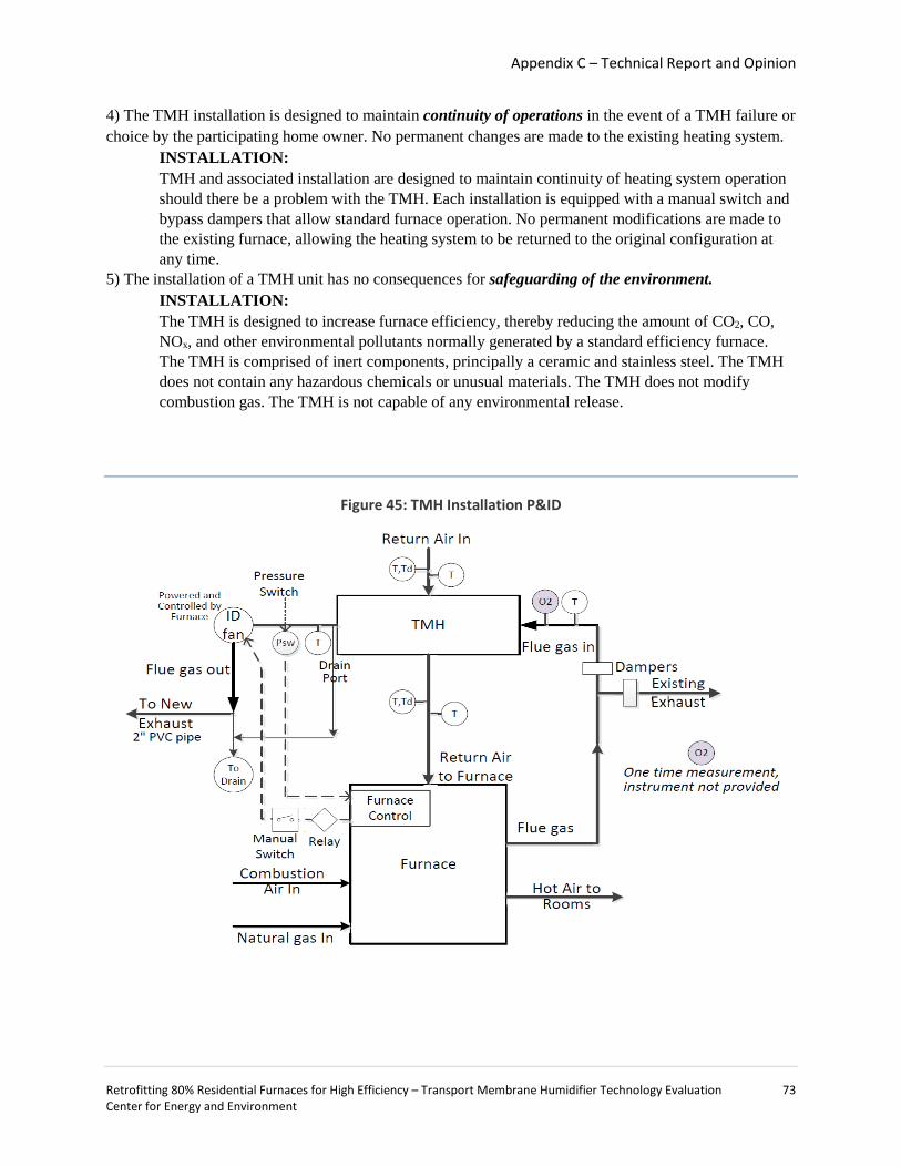
Appendix C – Technical Report and Opinion
Retrofitting 80% Residential Furnaces for High Efficiency – Transport Membrane Humidifier Technology Evaluation 73 Center for Energy and Environment
4) The TMH installation is designed to maintain continuity of operations in the event of a TMH failure or choice by the participating home owner. No permanent changes are made to the existing heating system.
INSTALLATION: TMH and associated installation are designed to maintain continuity of heating system operation should there be a problem with the TMH. Each installation is equipped with a manual switch and bypass dampers that allow standard furnace operation. No permanent modifications are made to the existing furnace, allowing the heating system to be returned to the original configuration at any time.
5) The installation of a TMH unit has no consequences for safeguarding of the environment. INSTALLATION: The TMH is designed to increase furnace efficiency, thereby reducing the amount of CO2, CO, NOx, and other environmental pollutants normally generated by a standard efficiency furnace. The TMH is comprised of inert components, principally a ceramic and stainless steel. The TMH does not contain any hazardous chemicals or unusual materials. The TMH does not modify combustion gas. The TMH is not capable of any environmental release.
Figure 45: TMH Installation P&ID
Appendix C – Technical Report and Opinion
Retrofitting 80% Residential Furnaces for High Efficiency – Transport Membrane Humidifier Technology Evaluation 74 Center for Energy and Environment
COMPARABLE PRODUCTS
Tjerland Auto-draft inducer Tjerland Auto-Draft Inducer Installation Instructions (http://www.tjernlund.com/Tjernlund_8504003.pdf) Tjerland In-Line Draft Inducers Reference Guide (http://www.tjernlund.com/Tjernlund_8500590.pdf)
AprilAire Series 500, 600, 700 return duct mounted whole house humidifier (http://www.aprilairepartners.com/products/category/humidifiers/83266.pdf)
REFERENCES
Wang, D., Bao, A., and Liss, W., “An Innovative Technology Development for Building Humidification and Energy Efficiency,” J. Sol. Energy Eng. 135(4),; doi: 10.1115/1.4025426
ATACHMENT A: Minnesota Administrative Rule 1300.0110
DUTIES AND POWERS OF BUILDING OFFICIAL.
Subp. 14. Performance-based fire and life safety design.
The code official may approve performance-based fire and life safety designs if the code official finds that the proposed design has been conducted by an approved method. Approved performance-based designs are evidence of compliance with the intent of the code. Approvals under this subpart are subject to the approval of the building code official whenever the design involves matters regulated by the building code.
A. Design goals, objectives, and performance criteria shall be approved by the code official before submission of a performance-based design report, calculations, or analysis results. As a minimum, an approved performance-based design shall address the following objectives:
(1) life safety of occupants; (2) firefighter safety; (3) property protection; (4) continuity of operations; and (5) safeguarding of the environment.
B. To determine the acceptability of a performance-based design, the code official may require the owner or agent to provide, without charge to the jurisdiction, a technical opinion and report. The code official may require the technical opinion and report to be prepared by, and bear the stamp of, a licensed design professional.
C. Performance-based designs shall be prepared by, and bear the stamp of, a licensed design professional competent in the area of work. The design professional shall provide written confirmation to the code official before a certificate of occupancy is issued that the performance-based design has been properly implemented, the operation or use of the building

Appendix C – Technical Report and Opinion
Retrofitting 80% Residential Furnaces for High Efficiency – Transport Membrane Humidifier Technology Evaluation 75 Center for Energy and Environment
is within the limitations of the design, and adequate controls are in place to maintain compliance with the conditions of the design throughout the life of the building.

Appendix C – Technical Report and Opinion
Retrofitting 80% Residential Furnaces for High Efficiency – Transport Membrane Humidifier Technology Evaluation 76 Center for Energy and Environment
ATTACHMENT B: SAMPLE LABORATORY TEST REPORT
ANALYSIS REPORT Transport membrane humidifier (TMH) unit listed above has passed performance, safety, and functional testing and the unit was found to meet GTI design specifications. The results in this report apply only to the unit listed above. Additional data are given in Appendix A. The test apparatus, instrumentation, and testing methodology are given in Appendix B.
TMH Combustion Gas Carryover Combustion gas concentrations were measuremed on the air side and flue gas side of the TMH unit during normal operation, and the measured gas component differences are shown in Table 1. All the values are within the instrument accuracy ranges. Therefore, this unit has no carry over of non-H2O combustion products from flue gas to return air. Individual return air and flue gas combustion gas component measurments are given in Table 4 in Appendix A.
Table 17: Lab combustion gas carryover results
Gas Measurement difference between flue gas and return air sides
Unit
O2 0.01 % CO2 -0.01 % CO 0 ppm NOx -0.14 ppm
TMH Performance Testing Preheating and humidification of return air is consistent with GTI performance expectations, Table 2 shows both air temperature and dew point increases. Individual return air and flue gas temperature and humidity measurements are given in Table 5 in Appendix A.
Table 18: Lab heat transfer and humidification performance results
Measurement Value Unit Air side temperature rise 3.9 ˚F
Air side dew point rise 2.0 ˚F Flue side temperature rise -146.7 ˚F
TMH Functional Testing Functional tests were performed to validate TMH and furnace operation. The flue gas bypass, safety pressure swtich, and inline inducer fan are operating correctly.
Table 19: Lab functional test results
Test Description Status Bypass Mode Standard furnace operation while in bypass mode PASS Heating Call TMH ID Fan enabled with call for heat PASS
Pressure Switch Furnace shutdown when negative pressure is lost PASS
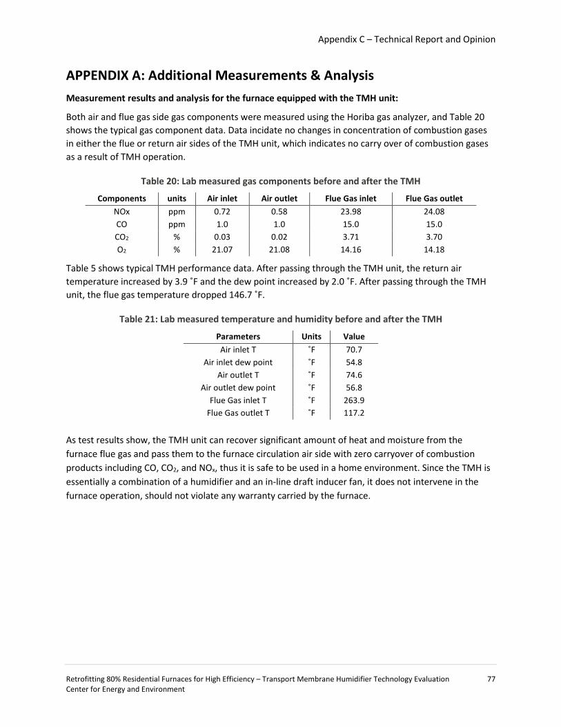
Appendix C – Technical Report and Opinion
Retrofitting 80% Residential Furnaces for High Efficiency – Transport Membrane Humidifier Technology Evaluation 77 Center for Energy and Environment
APPENDIX A: Additional Measurements & Analysis Measurement results and analysis for the furnace equipped with the TMH unit:
Both air and flue gas side gas components were measured using the Horiba gas analyzer, and Table 20 shows the typical gas component data. Data incidate no changes in concentration of combustion gases in either the flue or return air sides of the TMH unit, which indicates no carry over of combustion gases as a result of TMH operation.
Table 20: Lab measured gas components before and after the TMH
Components units Air inlet Air outlet Flue Gas inlet Flue Gas outlet NOx ppm 0.72 0.58 23.98 24.08 CO ppm 1.0 1.0 15.0 15.0 CO2 % 0.03 0.02 3.71 3.70 O2 % 21.07 21.08 14.16 14.18
Table 5 shows typical TMH performance data. After passing through the TMH unit, the return air temperature increased by 3.9 ˚F and the dew point increased by 2.0 ˚F. After passing through the TMH unit, the flue gas temperature dropped 146.7 ˚F.
Table 21: Lab measured temperature and humidity before and after the TMH
Parameters Units Value Air inlet T ˚F 70.7
Air inlet dew point ˚F 54.8 Air outlet T ˚F 74.6
Air outlet dew point ˚F 56.8 Flue Gas inlet T ˚F 263.9
Flue Gas outlet T ˚F 117.2 As test results show, the TMH unit can recover significant amount of heat and moisture from the furnace flue gas and pass them to the furnace circulation air side with zero carryover of combustion products including CO, CO2, and NOx, thus it is safe to be used in a home environment. Since the TMH is essentially a combination of a humidifier and an in-line draft inducer fan, it does not intervene in the furnace operation, should not violate any warranty carried by the furnace.
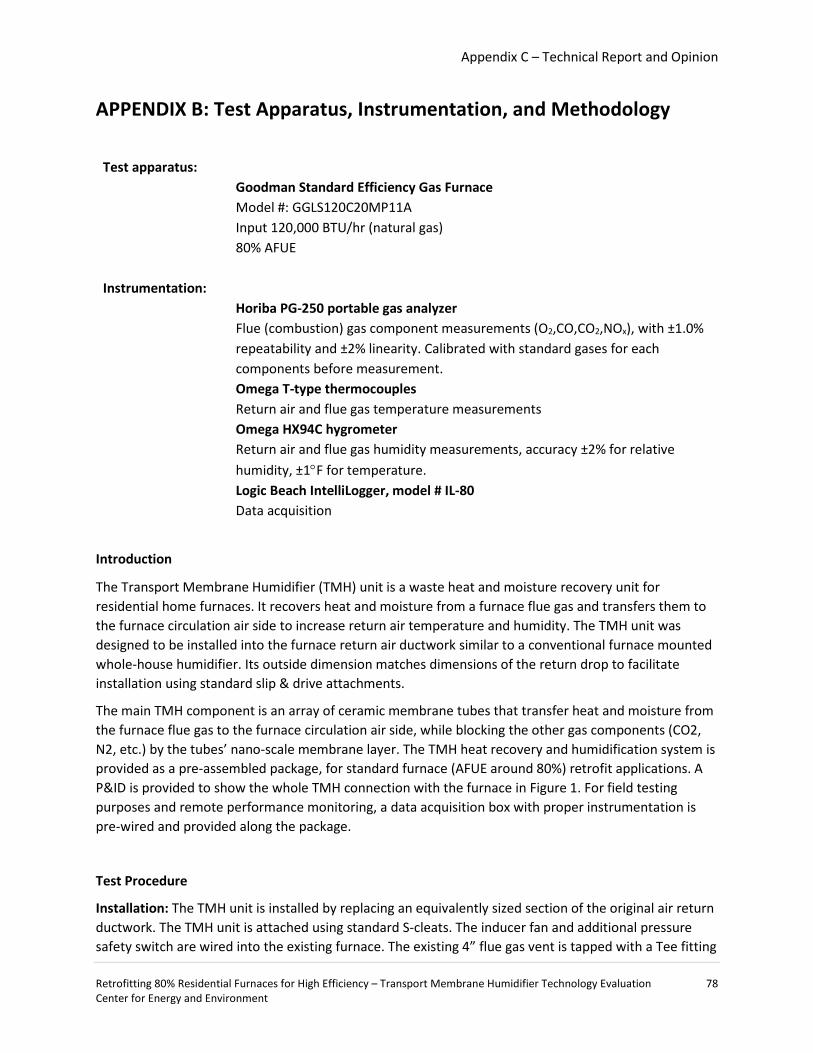
Appendix C – Technical Report and Opinion
Retrofitting 80% Residential Furnaces for High Efficiency – Transport Membrane Humidifier Technology Evaluation 78 Center for Energy and Environment
APPENDIX B: Test Apparatus, Instrumentation, and Methodology
Test apparatus: Goodman Standard Efficiency Gas Furnace
Model #: GGLS120C20MP11A Input 120,000 BTU/hr (natural gas) 80% AFUE
Instrumentation: Horiba PG-250 portable gas analyzer
Flue (combustion) gas component measurements (O2,CO,CO2,NOx), with ±1.0% repeatability and ±2% linearity. Calibrated with standard gases for each components before measurement.
Omega T-type thermocouples Return air and flue gas temperature measurements
Omega HX94C hygrometer Return air and flue gas humidity measurements, accuracy ±2% for relative humidity, ±1°F for temperature.
Logic Beach IntelliLogger, model # IL-80 Data acquisition
Introduction
The Transport Membrane Humidifier (TMH) unit is a waste heat and moisture recovery unit for residential home furnaces. It recovers heat and moisture from a furnace flue gas and transfers them to the furnace circulation air side to increase return air temperature and humidity. The TMH unit was designed to be installed into the furnace return air ductwork similar to a conventional furnace mounted whole-house humidifier. Its outside dimension matches dimensions of the return drop to facilitate installation using standard slip & drive attachments.
The main TMH component is an array of ceramic membrane tubes that transfer heat and moisture from the furnace flue gas to the furnace circulation air side, while blocking the other gas components (CO2, N2, etc.) by the tubes’ nano-scale membrane layer. The TMH heat recovery and humidification system is provided as a pre-assembled package, for standard furnace (AFUE around 80%) retrofit applications. A P&ID is provided to show the whole TMH connection with the furnace in Figure 1. For field testing purposes and remote performance monitoring, a data acquisition box with proper instrumentation is pre-wired and provided along the package.
Test Procedure
Installation: The TMH unit is installed by replacing an equivalently sized section of the original air return ductwork. The TMH unit is attached using standard S-cleats. The inducer fan and additional pressure safety switch are wired into the existing furnace. The existing 4” flue gas vent is tapped with a Tee fitting
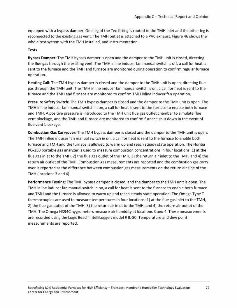
Appendix C – Technical Report and Opinion
Retrofitting 80% Residential Furnaces for High Efficiency – Transport Membrane Humidifier Technology Evaluation 79 Center for Energy and Environment
equipped with a bypass damper. One leg of the Tee fitting is routed to the TMH inlet and the other leg is reconnected to the existing gas vent. The TMH outlet is attached to a PVC exhaust. Figure 46 shows the whole test system with the TMH installed, and instrumentation.
Tests
Bypass Damper: The TMH bypass damper is open and the damper to the TMH unit is closed, directing the flue gas through the existing vent. The TMH inline inducer fan manual switch is off, a call for heat is sent to the furnace and the TMH and furnace are monitored during operation to confirm regular furnace operation.
Heating Call: The TMH bypass damper is closed and the damper to the TMH unit is open, directing flue gas through the TMH unit. The TMH inline inducer fan manual switch is on, a call for heat is sent to the furnace and the TMH and furnace are monitored to confirm TMH inline inducer fan operation.
Pressure Safety Switch: The TMH bypass damper is closed and the damper to the TMH unit is open. The TMH inline inducer fan manual switch in on, a call for heat is sent to the furnace to enable both furnace and TMH. A positive pressure is introduced to the TMH unit flue gas outlet chamber to simulate flue vent blockage, and the TMH and furnace are monitored to confirm furnace shut down in the event of flue vent blockage.
Combustion Gas Carryover: The TMH bypass damper is closed and the damper to the TMH unit is open. The TMH inline inducer fan manual switch in on, a call for heat is sent to the furnace to enable both furnace and TMH and the furnace is allowed to warm up and reach steady state operation. The Horiba PG-250 portable gas analyzer is used to measure combustion concentrations in four locations: 1) at the flue gas inlet to the TMH, 2) the flue gas outlet of the TMH, 3) the return air inlet to the TMH, and 4) the return air outlet of the TMH. Combustion gas measurements are reported and the combustion gas carry over is reported as the difference between combustion gas measurements on the return air side of the TMH (locations 3 and 4).
Performance Testing: The TMH bypass damper is closed, and the damper to the TMH unit is open. The TMH inline inducer fan manual switch in on, a call for heat is sent to the furnace to enable both furnace and TMH and the furnace is allowed to warm up and reach steady state operation. The Omega Type T thermocouples are used to measure temperatures in four locations: 1) at the flue gas inlet to the TMH, 2) the flue gas outlet of the TMH, 3) the return air inlet to the TMH, and 4) the return air outlet of the TMH. The Omega HX94C hygrometers measure air humidity at locations 3 and 4. These measurements are recorded using the Logic Beach IntelliLogger, model # IL-80. Temperature and dew point measurements are reported.

Appendix C – Technical Report and Opinion
Retrofitting 80% Residential Furnaces for High Efficiency – Transport Membrane Humidifier Technology Evaluation 80 Center for Energy and Environment
Figure 46: Laboratory testing setup including data logger and instrumentation
Appendix C – Technical Report and Opinion
Retrofitting 80% Residential Furnaces for High Efficiency – Transport Membrane Humidifier Technology Evaluation 81 Center for Energy and Environment
ATTACHMENT D: PARTICIPATION AGREEMENT EXHIBIT C
Center for Energy and Environment Transport Membrane Humidification Research
Homeowner Agreement The purpose of this Agreement is to set forth an understanding between the Center for Energy and Environment (“CEE”) and the homeowner identified below (“HOMEOWNER”) for purposes of transport membrane humidification research at the property located at:
HOMEOWNER Name Address City, State, Zip
HOMEOWNER represents that HOMEOWNER is the rightful owner of the property and, as such, has agreed to participate in a research project to test the energy efficiency of transport membrane humidification (“TMH”) units (“Field Demonstration Project”). Except as expressly set forth herein, HOMEOWNER agrees to participate in the Project without compensation. In exchange for the mutual representations and commitments set forth herein and other good and valuable consideration, the receipt and adequacy of which is hereby acknowledged, CEE and HOMEOWNER agree to the following terms and conditions. HOMEOWNER agrees to:
1. Allow CEE and its contractors reasonable access to the property for the purpose of installing, maintaining, calibrating or adjusting, and removing the TMH and associated test equipment for a period of not less than 18 months from the date of installation. HOMEOWNER understands that a licensed HVAC contractor will install the TMH device on the property, which may require alterations or modifications to the furnace, ductwork and exhaust flue required for the installation of the TMH device.
2. Allow CEE employees to install temperature sensors and data logging equipment to monitor furnace performance, gas usage and other variables relating to the Project. HOMEOWNER understands that monitoring will be conducted for a period of approximately 18 months.
3. Not move, unplug, obstruct or otherwise disturb or interfere with the proper operation of the furnace, TMH device or associated test equipment.
4. Allow CEE employees access to the property approximately once a month to inspect the test equipment. 5. Log any changes in performance of the heating system on a daily log provided by CEE. CEE will instruct
HOMEOWNER on use of the daily log at the time of installation. 6. Complete and return to CEE as many as 4 short questionnaires during the study. These questionnaires
will address the performance of the TMH and the heating and comfort quality delivered. 7. Allow data to be collected over HOMEOWNER’S local internet connection, if possible. If this is not
possible, another collection method will be jointly agreed upon by CEE and HOMEOWNER. 8. Use and operate the TMH device in accordance with instructions, warnings and specifications received
from CEE. HOMEOWNER assumes any and all risks associated with the TMH. HOMEOWNER understands

Appendix C – Technical Report and Opinion
Retrofitting 80% Residential Furnaces for High Efficiency – Transport Membrane Humidifier Technology Evaluation 82 Center for Energy and Environment
that the TMH is an experimental device, and while it is intended to save energy, it is possible that energy use will not decrease and may even increase. In addition, the TMH may reduce the summer cooling efficiency of a central air conditioning unit which shares the same air handler as the furnace.
9. Notify CEE immediately if carbon monoxide (CO) detector placed near the TMH produces an alarm or warning of any kind.
At the conclusion of the Project, the TMH device and monitoring equipment will be removed by or at the direction of CEE and all duct work will be returned to its original condition. HOMEOWNER understands that, after the monitoring period has ended and the test equipment is removed, HOMEOWNER will assume full and complete responsibility for any maintenance, replacement, or repair of the existing furnace that remains on the property. CEE agrees to provide HOMEOWNER with a summary of the test results at no cost or charge. HOMEOWNER understands that the test results are provided “as is” and that CEE does not warrant the accuracy or reliability of the testing methodology or results, or any conclusions that may be drawn from such test results. ALL WARRANTIES OF ANY KIND, EXPRESS OR IMPLIED, INCLUDING BUT NOT LIMITED TO THE IMPLIED WARRANTIES OF MERCHANTABILITY AND FITNESS FOR A PARTICULAR PURPOSE, ARE EXPRESSLY DISCLAIMED. HOMEOWNER further understands that CEE will compile the test results into a database containing other TMH device test results and may make the test results and/or database available to the State of Minnesota, the public or others. The test results will reflect the city and state where the samples were taken and when, but will not disclose HOMEOWNER’s name. HOMEOWNER hereby grants CEE express permission to use the test results and/or database containing the test results as it sees fit.
HOMEOWNER ACKNOWLEDGEMENT HOMEOWNER ACKNOWLEDGES THAT HE OR SHE HAS READ THIS AGREEMENT THOROUGHLY AND UNDERSTANDS AND ACCEPTS THE TERMS CONTAINED HEREIN AND THAT NO ORAL REPRESENTATIONS OR STATEMENTS OR INDUCEMENTS HAVE BEEN MADE TO HIM OR HER THAT CHANGE, ALTER OR MODIFY ANYTHING WITHIN THIS WRITTEN AGREEMENT. HOMEONWER HEREBY REPRESENTS AND WARRANTS THAT HE OR SHE HAS THE AUTHORITY TO AGREE TO THE TERMS CONTAINED HEREIN ON BEHALF OF ALL HOMEOWNERS OR OTHER OCCUPANTS OF THE PROPERTY IDENTIFIED HEREIN, INCLUDING HOMEOWNER’S SPOUSE, CHILDREN, HEIRS, NEXT OF KIN, ASSIGNS, PERSONAL REPRESENTATIVES, GUESTS OR OTHER OCCUPANTS. IN THE EVENT ANY PORTION OF THIS AGREEMENT IS HELD INVALID, IT IS AGREED THAT THE BALANCE SHALL, NOTWITHSTANDING, CONTINUE IN FULL FORCE AND EFFECT. HOMEOWNER UNDERSTANDS AND ACKNOWLEDGES THAT THE TMH UNIT (“EQUIPMENT”), AND THE DATA ACQUISITION SYSTEM RELATED THERETO (THE “DAS”), IS A TEST UNIT AND THIS FIELD DEMONSTRATION PROJECT IS EXPERIMENTAL IN NATURE. AS SUCH, IT IS PROVIDED TO HOMEOWNER “AS IS” AND “WITH ALL FAULTS.” CEE AND GAS TECHNOLOGY INSTITUTE (“GTI”) MAKE NO REPRESENTATIONS, WARRANTIES OR GUARANTEES, EITHER EXPRESSED OR IMPLIED (INCLUDING, BUT NOT LIMITED TO, WARRANTIES OF FITNESS FOR A PARTICULAR PURPOSE, MERCHANTABILITY OR NON-INFRINGEMENT), AND EXPRESSLY DISCLAIM ANY LIABILITY ARISING FROM, ASSOCIATED WITH OR RELATED TO: (I) HOMEONWER’S PARTICIPATION IN THIS FIELD DEMONSTRATION PROJECT; OR (II) THE EQUIPMENT, THE DAS OR ANY APPLIANCE OR EQUIPMENT OF HOMEOWNER USED IN CONNECTION WITH THIS FIELD DEMONSTRATION PROJECT (INCLUDING, BUT NOT LIMITED TO, USE, INSTALLATION, QUALITY, SAFETY, DESIGN, PERFORMANCE, ENERGY OR COST SAVINGS OR ANY OTHER ASPECT RELATED THERETO).
Appendix C – Technical Report and Opinion
Retrofitting 80% Residential Furnaces for High Efficiency – Transport Membrane Humidifier Technology Evaluation 83 Center for Energy and Environment
HOMEOWNER HEREBY RELEASES AND DISCHARGES CEE, THE STATE OF MINNESOTA, GTI AND THEIR RESPECTIVE SUBSIDIARIES, AFFILIATES, OFFICERS, DIRECTORS, EMPLOYEES, AGENTS AND CONTRACTORS, INDIVIDUALLY AND COLLECTIVELY (COLLECTIVELY, “AFFILIATES”) FROM ANY AND ALL CLAIMS, DEMANDS, LAWSUITS, JUDGMENTS, LOSSES, DAMAGES, EXPENSES (INCLUDING TAXES), FEES (INCLUDING LEGAL FEES), COSTS AND LIABILITIES (COLLECTIVELY, “LOSSES”) ARISING FROM, ASSOCIATED WITH OR RELATED TO (I) HOMEOWNER’S PARTICIPATION IN THIS FIELD DEMONSTRATION PROJECT; OR (II) THE EQUIPMENT, THE DAS OR ANY APPLIANCE OR EQUIPMENT OF HOMEOWNER USED IN CONNECTION WITH THIS FIELD DEMONSTRATION PROJECT (INCLUDING, BUT NOT LIMITED TO, USE, INSTALLATION, QUALITY, SAFETY, DESIGN, PERFORMANCE, ENERGY OR COST SAVINGS OR ANY OTHER ASPECT RELATED THERETO). HOMEOWNER AGREES THAT SUCH RELEASE AND DISCHARGE INCLUDES, BUT IS NOT LIMITED TO, ANY AND ALL DIRECT, INDIRECT, SPECIAL, INCIDENTAL OR CONSEQUENTIAL DAMAGES WHETHER BASED ON CONTRACT, TORT, NEGLIGENCE, STRICT LIABILITY, WARRANTY, INDEMNITY OR ANY OTHER LEGAL THEORY. HOMEOWNER SHALL INDEMNIFY, DEFEND AND HOLD HARMLESS CEE, THE STATE OF MINNESOTA, GTI AND THEIR RESPECTIVE AFFILIATES FROM AND AGAINST ANY AND ALL LOSSES ARISING FROM, ASSOCIATED WITH OR RELATED TO (I) HOMEOWNER’S PARTICIPATION IN THIS FIELD DEMONSTRATION PROJECT; OR (II) THE EQUIPMENT, THE DAS OR ANY APPLIANCE OR EQUIPMENT OF HOMEOWNER USED IN CONNECTION WITH THIS FIELD DEMONSTRATION PROJECT (INCLUDING, BUT NOT LIMITED TO, USE, INSTALLATION, QUALITY, SAFETY, DESIGN, PERFORMANCE, ENERGY OR COST SAVINGS OR ANY OTHER ASPECT RELATED THERETO). HOMEOWNER ACKNOWLEDGES AND AGREES THAT THE PROJECT IS NOT A “CONSUMER SALE” OR “CONSUMER TRANSACTION” OF ANY SORT. HOMEOWNER UNDERSTANDS AND ACKNOWLEDGES THAT THE STATE OF MINNESOTA, GTI AND THEIR RESPECTIVE AFFILIATES ARE THIRD-PARTY BENEFICIARIES OF THE “HOMEOWNER ACKNOWLEDGEMENT” OF THIS AGREEMENT AND THAT THE AGREEMENTS AND COVENANTS INCLUDED THEREIN ARE FOR THE BENEFIT OF THE STATE OF MINNESOTA, GTI AND THEIR RESPECTIVE AFFILIATES.
CEE Representative
Print Name
Date
HOMEOWNER
Print Name
Date