return torque micro-bearing refit scott kruse jared smith jacob reese john anderson cherrod williams
TRANSCRIPT

Return Torque Micro-Bearing Refit
Scott Kruse
Jared Smith
Jacob Reese
John Anderson
Cherrod Williams

Overview• Project Introduction
• Design Requirements
• Concept Generation/Selection
• Design Progression
• Material/Magnetic Selection
• Large-Scale Prototype Construction
– FDM (Rapid Prototyping)
– Magnetic Construction
– Assembly
• Results
• Future Work

Project Introduction
• Design Statement: •Design of a micro return torque bearing for actuation purposes through the use of permanent magnets
• Design Specifics:•When an external torque is applied to the bearing, the bearing reacts by producing an opposing torque.•Once the external torque is removed, the bearing returns to its initial position.•Traditionally accomplished with springs.
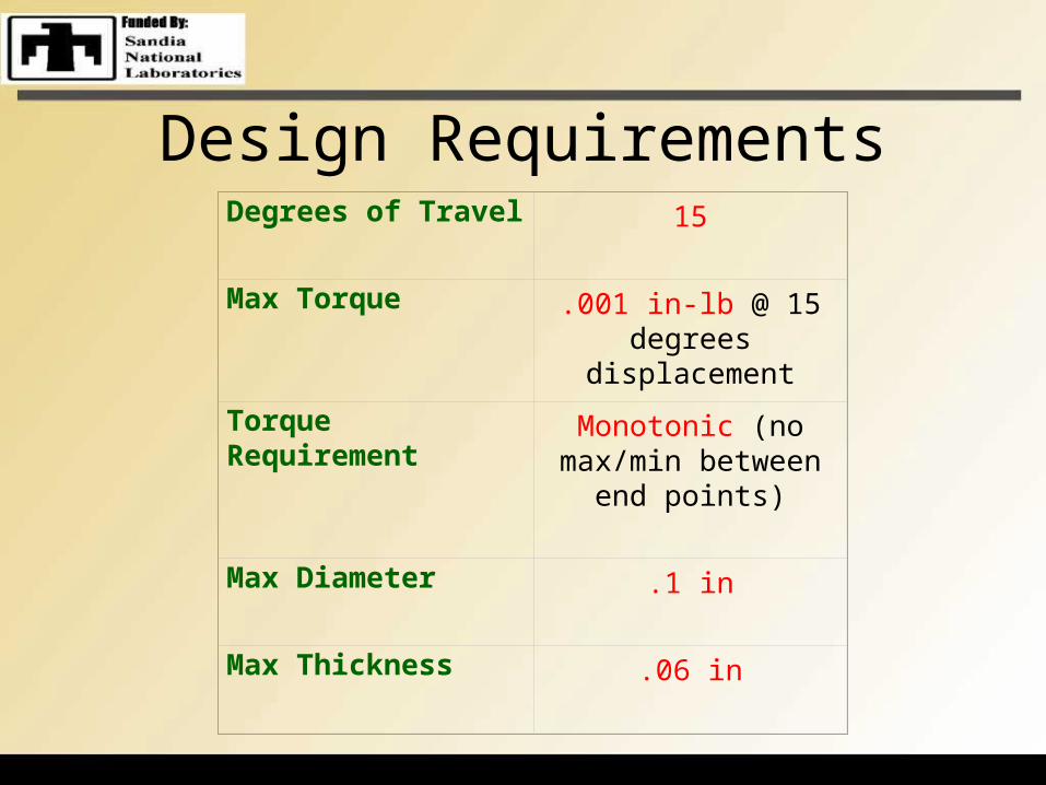
Design RequirementsDegrees of Travel 15
Max Torque .001 in-lb @ 15 degrees displacement
Torque Requirement Monotonic (no max/min between end
points)
Max Diameter .1 in
Max Thickness .06 in

Proposed Concepts
Shaft/pin
Rotational Magnetic Pair
Axial Magnetic PairAxial Magnetic Pair
Grounded Outer Bearing Surface
Inner Bearing(attached to pin)

Initial Chosen Concept
• Variant of Concept 3• Allows multiple
moment arms• Repeatable/expandable
geometry• Travel limiter inherent
in design• Simple, balanced and
symmetric

Design Progression
• More robust design
• Added magnetic material to produce necessary torque
• Uses only repulsive forces to generate return torque
– Better model of a spring

Chosen Material: Polysilicon• Stronger than steel• Low coefficient of friction• Extremely flexible• Directly compatible with modern IC fabrication• Used extensively in micro-machining

Magnetic Selection
*Sintered NeFeB 48 was chosen for our application.

Torque Results
Torque vs. Angular Displacement
0
0.0002
0.0004
0.0006
0.0008
0.001
0.0012
0 2 4 6 8 10 12 14 16
Angular Displacement (degrees)
To
rqu
e (i
n-l
b)

Field Visualization

Geometry Results (inches)

Results SummaryDegrees of Travel 15
Max Torque .001 in-lb @ 15 degrees displacement
Monotonic Torque? Yes
Diameter .08 in
Thickness .06 in

Construction of Large-Scale Prototype

Fused Deposition Modeling (FDM)
Rapid Prototyping Process
– Adds layers of material instead of subtracting
– Can construct complicated geometries
– Fast turn around from CAD files to working prototypes
– Utilizes ABS plastic

Prototyping Process

Magnet Construction
• Purchased small Neodymium magnets• Set magnets in blocks of resin of the necessary
geometry

Assembly
•Cut Plexiglas to required diameter •Epoxied magnetic blocks in the appropriate locations•Completed the assembly by adding the parts created through FDM

Prototype Results

Future Work
• Research attachment details for the micro-scale
• Run cost/benefit analysis for the replacement of springs with permanent magnets
• Apply design on the micro-scale

Acknowledgements
• Dr. Masson• Dr. Gielisse• Dr. Luongo• Gary the Prototype
Guy• Ron Wild and Dr.
Greenwood