reusing waste heat from cryptocurrency mining to heat
TRANSCRIPT

Tri Nguyen Anh Hoang
Reusing Waste Heat from Cryptocurrency Mining to Heat Multi-Family House
Metropolia University of Applied Sciences
Bachelor of Engineering
Sustainable Building Engineer
Thesis
15 April 2018

Abstract
Author Title Number of Pages Date
Tri Nguyen, Anh Hoang Reusing Waste Heat from Cryptocurrency Mining to Heat Multi-Family House 81 pages + 8 appendices 15 April 2018
Degree Bachelor of Engineering
Degree Programme Civil Engineering
Professional Major Sustainable Building Engineering
Instructors
Sergio Rossi, Lecturer Jorma Säteri, Head of Department
The objective of this thesis was to find solutions for reusing waste heat from cryptocurrency mining process to supply the heating demand in Finnish detached house. The focus of the study was on identifying and proposing suitable and optimal technologies to integrate sys-tems. The proposed technologies were tested in practical case to strengthen its capabilities and possibilities. Since mining cryptocurrency creates a lot of waste heat and Finland re-quires a lot of heating supply in cold period, this study provided useful information and opti-mal solutions for this problem. To achieve its objective, this study reviewed the Finnish heating system and market, and provided information about heating and cooling technologies. Then, the concept of crypto-currency and its mining process were introduced to give a brief understanding of the problem. Later, integrating solutions were analyzed from existing strategies and innovative suggestions. The practical case was the Hyrsylä Co-housing project in Lohja. The targets were to calculate the building heating demand by IDA ICE and identify the possible number of mining rigs to supply the heating demand of the project. Some practical solutions were suggested to avoid the overheating problem in the summer. As a result of this project, three possible solutions were presented for using the waste heat from cryptocurrency mining process and sufficient information related to heating and cooling technologies, cryptocurrency concept and mining technologies. It was possible to reuse heat from two mining rigs to supply the domestic hot water consumption in the project.
Keywords cryptocurrency mining, waste heat, data center, domestic hot water, heating demand, recycling waste heat

Contents
1 Introduction 1
1.1 The Objective and Research Question 2
1.2 The Structure and Research Team 2
2 Domestic Heating Market in Finland 4
2.1 Heating Energy in Finland 4
2.2 Heating Technologies in Finland 8
2.2.1 District Heating 8
2.2.2 Heat Pump 10
2.2.3 Biomass – Wooden Pellet 16
2.2.4 Mechanical Heat Recovery Ventilation 17
2.3 Combined Technologies 19
3 Cryptocurrency and Its Mining Process 22
3.1 Concept of Currency 22
3.2 Cryptocurrency 25
3.2.1 Definition 25
3.2.2 Blockchain Technology 26
3.2.3 Future of Cryptocurrency 29
3.3 Cryptocurrency Mining Process 31
3.3.1 Definition 31
3.3.2 Modes of Mining Processes 32
3.4 Mining Processors 34
3.5 Problems in Cryptocurrency Mining 38
4 Exploitation of Waste Heat from Processor 40
4.1 Cooling of Mining Processors 40
4.1.1 Chilled Water System Cooling 43
4.1.2 Pumped Refrigerant for Chilled Water Systems 44
4.1.3 Computer Room Air Conditioning 45
4.1.4 Self-Contained Cooling System 47
4.1.5 Direct Fresh Air Evaporative System 47
4.1.6 Indirect Air Evaporative System 48

4.2 Reusing Waste Heat Solutions 49
4.2.1 Stand-Alone System 50
4.2.2 Combined to Another system 51
4.3 Innovative Integrating Strategies 52
4.3.1 Combined with Air-to-Water Heat Pump 52
4.3.2 Combined with Exhaust-Air Heat Pump 53
4.3.3 Combined with a Compact Heat Pump Unit 55
5 Practical Case Introduction 58
5.1 The Hyrsylä Co-Housing Project 58
5.2 Building Structure and Thermal Envelop Detail 60
5.3 The Existing HVAC System 61
6 Research Approach and Method for Testing 63
6.1 Building Energy Simulation 63
6.2 Data Input in IDA ICE 64
6.3 Method of Testing the HVAC System and Feasibility of Mining Rig 66
7 Results and Discussion 69
7.1 The Heating Demand of Hyrsylä School 69
7.2 Heating Supply from Mining Rig 71
7.3 The Final Result and Discussion 72
8 Conclusion 75
References 77
Appendices
Appendix 1. Architectural Drawing of Hyrsylä Co-Housing Project
Appendix 2. Heating and Energy Report for Hyrsylä Co-Housing Project

List of Abbreviations
ICOs Initial coin offering. Start-up cryptocurrencies that is to be released in the
future once the call for initial investment completed.
HDD Hard disk drive. A data storage device, allows storing or transferring data.
USB drive Universal Serial bus drive. A device for storing data with a smaller capacity
than HDD.
CPU Central Processing Unit. Computer component, handles basic IT tasks.
GPU Graphics Processing Unit. Computer component, handles advanced
graphics tasks.
HVAC Heating, ventilation, and air conditioning. Building services system.
COP Coefficient of Performance. A measurement to calculate the efficiency of a
heat pump.
MVHR Mechanical ventilation heat recovery

1
1 Introduction
The increasing popularity of cryptocurrency creates an increasing amount of interest in
people. Cryptocurrency can bring a tremendous profit in a short time. Therefore, more
and more money is invested in this business. There are two ways to make a profit on
cryptocurrency: one is from trading, the other is from the mining activities. The value of
cryptocurrency is still a question mark, it is unstable and unpredictable. Therefore,
trading in cryptocurrency is considered a risky investment. Thus, the mining process is
believed to be the safer way to make a profit. However, this process produces a massive
amount of thermal energy. It creates an overheating problem and can cause facilities
breakdown during the mining process. A cooling solution needs to be applied to deal with
this high thermal energy, and extra energy is consumed. (Khemarattana 2017: 3-9.)
A Finnish multi-family house also consumes a vast amount of energy for heating due to
the extended cold period in the country. The energy used for heating comprises 70 % to
80 % of the total energy consumption of the house and the lifetime of a building is usually
around 50 years to 70 years (Statistic Finland 2017). That makes the total consumption
for heating demand a major question to be solved. To be sustainable, a reduction in
heating demand is desirable, and better HVAC systems need to be developed.
The heating energy problems from the mining process and a Finnish multi-family house
may be linked to be an interesting study. Pedro Aibeo who is an architect and Mikko
Loukola who is a cryptocurrency investor, are contemplating a combined solution to ap-
ply to their Hyrsylä project. It is a renovation project of a hundred years old school to a
co-housing dwelling located in Lohja. Its aims are to create new living spaces and sharing
spaces for local people and business. Finding solutions to integrate the waste heat from
mining production to the HVAC system of the building can bring a double benefit to house
owners. The extra heat from the mining process can be used to supply a home’s heating
demand. The profit from cryptocurrency mining can also bring extra benefits for the
owner. However, there is no primary research on this issue since cryptocurrency is still
an unknown topic and no one can be sure about its future. This study can fill this gap
and, perhaps, can encourage future research.

2
1.1 The Objective and Research Question
This thesis aims to investigate the possibility of reusing waste heat from a mining system
by integrating it to the HVAC system in a Finnish multi-family house. The primary focus
is on finding optimal options to increase the energy efficiency of the building. The options
are tested at a project in Hyrsylä to establish the best-integrated one. Energy simulation
software IDA ICE is used to simulate the options and evaluate the energy performance
and feasibility of the system.
The output of this thesis brings benefits to the involved parties. First, the architects and
engineers of the project in Hyrsylä receive the energy report of the heat recycling solution
in their house. Second, the feasibility of the project can be evaluated. The study also
introduces a handful of information related to cooling and heating technologies.
Cryptocurrency mining system is similar with small data centre system. Decentralize data
center to home scale may be an option in the future. Thus, it can benefit for future
research to propose better solutions and systems
1.2 The Structure and Research Team
This research looks into cryptocurrency mining technology and cooling/heating
technology. Primary data were collected from an interview with Mister Pedro Aibeo and
Mister Mikko Loukola.
The first chapter of this thesis introduces the general goals and subjects. The back-
ground and motivation of the research are presented; the objectives and research ques-
tion are found in chapter 1.1; the basic structure of this thesis is introduced in chapter
1.2. The second chapter, written mostly by Tri Nguyen, introduces the heating system,
heating sources, and heating market in Finland. It also provides information on the op-
eration of various heating systems. The technical concepts behind each heating source
are explained briefly. The third chapter introduces cryptocurrency, a novel concept. The
definition, technologies, future and technical problems of cryptocurrency facilities and its
mining process are explained principally by Anh Hoang. The fourth chapter, also by Anh
Hoang, discusses the combination between a cryptocurrency mining system and building
services systems. This chapter provides a general concept of how to deal with the heat

3
problem of mining facilities. Furthermore, innovative ideas for the recycling methods are
listed in this chapter.
The fifth chapter by Tri Nguyen is a brief introduction to the practical case. The infor-
mation is provided by the architect and engineers of the Hyrsylä project. Technical draw-
ings and the current condition of the house are introduced in this chapter. The sixth
chapter, by Anh Hoang discusses the testing method of the solutions proposed in chapter
four. IDA ICE is used as energy simulation software. Also, the process of data collection
and inputting is presented. Finally, the results of the final year project are presented in
chapter seven, and a concluding discussion is the topic of chapter eight.

4
2 Domestic Heating Market in Finland
In chapter 2, the Finnish heating consumption is explained briefly to provide general en-
ergy situation in Finland. After that, different heating sources and technologies available
for Finnish detached houses are researched and defined to identify integrating methods.
Chapter 2.1 describes the energy sources and consumption market for Finnish house-
holds. Chapter 2.2 introduces different familiar heating sources and technologies avail-
able in Finland. Finally, chapter 2.3 lists all possible current technologies to accumulate
and recover the unused heat.
2.1 Heating Energy in Finland
Heating energy is necessary and essential for Finnish climate which has an extended
cold period during the year. The yearly average ambient temperature was around from
1 to 6 degrees Celsius in 2016. The cold period commonly lasts for about five to six
months (Statistic Finland 2017). Thus, the heating demand for space heating and do-
mestic hot water is evident and significant throughout the year. There are several energy
sources for heating production in Finland. The most common one is from the Combined
Heat and Power plant (CHP) which generates a massive amount of hot water and elec-
tricity. Thus, district heating plays a vital role as an energy source. Besides that, heat
can also be produces in a small scale for a multi-family house by fuel combustion. The
fuel used for burning can be peat, biomass or oil, depending on the combustion system.
Electrical heating energy source also cannot be ignored since there are so many tech-
nologies developed with a high coefficient of performance such as heat pump, mechan-
ical ventilation, and condensing boiler. Also, electricity comprises a significant share in
the total energy sources for heating demand in Finland. (Statistic Finland 2017.)
According to Statistics of Finland, there are three sources of energy for space heating:
district heating, wood, and electricity. Figure 1 briefly presents the energy consumption
in Finnish households by energy source in 2016. (Statistic Finland 2017.)

5
Figure 1. Energy Consumption in households by energy source in 2016 (Statistic Finland 2017).
Figure 1 indicates the total share of heating sources. Electricity took 34 % of the share.
In that portion, 64 % was used for heating of residential buildings and only 36 % was
used for household appliances. The conventional energy sources, wood burning and
light fuel oil are still in the market. Light fuel oil covered 6 % of the total energy in 2016,
and it was decreasing due to building renovations and upgrading to more energy efficient
heating systems. District heat and electricity consumed most energy. Followed by wood
with 23 % of the total energy consumption. (Statistic Finland 2017.)
Depending on type and size of the building, the share of heating sources is also different.
Based on Statistic Finland, figure 2 shows heating sources for different common types
of residential building. (Statistic Finland 2017.)

6
Figure 2. Energy sources for space heating by building types (Statistic Finland 2017).
As depicted in figure 2, a single-family house mostly uses from wood or peat and elec-
tricity for space heating. The amount of heat pump usage keeps increasing due to the
improved technology and its efficiency. Multi-family houses use mostly energy from dis-
trict heating, although some use oil and direct electricity. District heating system is not
used a lot for single-family houses because of lack infrastructure and high initial cost.
Finally, the commercial and public building also use mainly district heating system and
oil for supplying heating. However, some heat pumps are used for space heating in
office-buildings. Moreover, this amount increases every year from the year of 2000.
Thus, the electricity consumption for heating also increased because the electricity used
for heat pumps is considered as heating electricity consumption. In new buildings, a heat
pump is often used to replace fuel oil. (Statistic Finland 2017.)
Heating energy is mainly used for space heating and domestic hot water production.
Many factors affect the heating demand of the building. The most significant one is the
building size. A bigger building always consumes more energy. Furthermore, the climate,
thermal envelope, building orientation, occupant behavior and heating system also con-
tribute to the differences in building heating consumption. (Santin, Olivia, Guerra, Itard,
Laure and Visscher, Henk 2009.) The energy consumption in Finnish households change
from year to year due to the changing in outdoor temperature. The total Finnish housing
energy consumption in 2016 was 67 terawatt hours (TWh), an increase of 12 % in space
heating and 5 % in household appliances compared to the previous year. The weather

7
in 2016 was colder than in 2015, leading people to use more electricity to heat up their
houses and cars. The energy consumption in households 2016 was introduced in figure
3 (Statistic Finland 2017).
Figure 3. Energy consumption in households 2010-2016 (Statistic Finland 2017).
Figure 3 shows that space heating covers 68 % of the total consumption. The heating of
domestic hot water is 15 %. The percentage is fairly constant since the population of
Finland does not increase dramatically. In 2016, the heating of space and water of resi-
dential buildings consumed 46 TWh of energy. Another category of energy usage is
electrical equipment, lighting, and cooking which cover 13 %. Finally, the last category,
sauna is 5 %. The electricity consumption for housing appliances take around 20 % of
the final energy consumption. There was also some indication of improvement in energy
efficiency from 2010 to 2016. The energy consumption rises fairly slow although the
heating area increases one percent per year. (Statistic Finland 2017.)

8
2.2 Heating Technologies in Finland
An overview of standard technologies provides a general understanding of the heating
sources for residential building in Finland. This chapter discuses four common and sus-
tainable heating technologies, district heating, heat pump, biomass, and heat recovery
ventilation, to understand the primary function of the system.
2.2.1 District Heating
District heating is the most common heating source in Finland. It was introduced to the
market in the 1950s. It is getting more and more popular, and it is available in almost
every Finnish town. According to Finnish Energy Industries, about 2.5 million Finns who
use a district heating system for their heating source in 2007. Also, more than 60 % of
public buildings and offices, around 95 % of apartments, and 50 % of terraced houses
also use district heating as a heating source. The consumption of district heating in-
creases, and more detached houses considers it as a sustainable and economical op-
tion. The district heating system is getting more sustainable as renewable sources such
as biomass, biogas, and residential wastes are used as fuel. District heating can be
considered as a renewable and reliable future energy source. (Finnish Energy Industries
2007.)
According to Danfoss, a leading company who provides district heating system equip-
ment and design and consultant services, district heating is a thermal energy network
which provides hot water to a building through pre-insulated pipes. The hot water acts
as a heat transfer liquid and can be connected directly or indirectly, i.e., with or without
heat exchanger from the production site to the end user. District heating conveniently
can provide space heating together with domestic hot water. Therefore, in summer the
district heating can be operated to supply domestic hot water. The district heating system
can be divided into three parts: production site, distribution system, and consumption
system. Figure 4 shows a primary district heating system with substations from the pro-
duction site to a consumption visa the distribution channel. (Danfoss 2018.)

9
Figure 4. District heating system. (Danfoss 2018.)
As seen in the figure 4, the hot water can be generated by heating plants, pure heat
producers or from wastewater in combined heat and power plants (CHP) at the produc-
tion site. In Finland, the district heating is mostly coming from CHP plants which are
energy efficient and sustainable. The distribution system includes the pre-insulated pip-
ing network which connects the production site to the consumption system. Usually, the
pipping supplies the hot water with the temperature around 120 0C and temperature of
water in return pipe is around 60 0C. Circulation pump maintains the circulation of hot
water at the production site. When the distribution distance is long, boosting sub-station
with a heat exchanger can be installed to maintain the pressure and temperature. In
Finland, there is additional heat exchanger at the consumption place to separate the
water and control the heat input to the building. (Danfoss 2018.)
A district heating system is the best for dense areas with high energy demand. The fuel
used in CHP or boosting station can be flexible and come from renewable sources. Thus,
the security of supply is improved and enhanced. With a district heating system, the
HVAC system at the end user can be simplified and easy to install. The system needs
minimal maintenance fee, required less space, and is very safe compared to other
technologies such as a combustion boiler. Finnish district heating provides not only hot
water but also cooling water as well. Thus, the system facility can be used all the time.
However, there are some limitations to the system such as the availability of the facility.
The initial cost can be higher than that of another system if the district heating system
cannot available nearby. It is not suitable for small buildings less than 160 m2 and re-
quires an emitter to transfer the heat by floor heating or radiator. Where available, district
heating always is the best option as a heating source, and it is an economic and sustain-
able source.

10
2.2.2 Heat Pump
Number of heat pumps in Finland has been increasing and become the most common
heat source in new detached houses. According to Sulpu, the Finnish heat pump asso-
ciation, more than 70 % of new detached houses have chooses to use heat pump as
heating sources. In 2017, more than 60,000 heat pump units were sold, and the market
sale was up to half a billion euro a year in Finland. Thus, the heat pump plays a significant
role, and it could be considered a renewable heating source with various technologies
such as air source heat pump, ground source heat pump, and air-to-water heat pump.
The most common one in the single-family house is an air-to-air heat pump. Followed by
a geothermal heat pump or an exhaust-air heat pump. Furthermore, the heat pump is
replacing oil-fired boilers, but they still cover small portion of the total market. (Sulpu
2018.)
The heat pump has become more popular because its coefficient of performance (COP)
is higher than other heating source technologies. It means that heat pump can save
electricity and is an optimal option to replace boiler or event district heating. According
to the Finnish heat pump association, heat pumps reduces 50 % of district heating or
other energy consumption in apartment buildings (Sulpu 2018). Heat pumps can be a
suitable alternative for scarcely populated areas or if there are no district heating system
available. With a high COP (up to COP 6), a heat pump can save more electricity, and
could be supplied by renewable electricity, such as power voltage or wind turbine.
In general, a heat pump extracts heat from one place and transfers it to another place
by evaporation and condensation. This basic technique is not new and has been used
for decades in air conditioners, and refrigerators for example. The energy for running a
heat pump is electricity since it needs an operating circulation pump inside the device.
However, the electricity consumption of a heat pump is considered low, and it can gen-
erate a lot of heat through the process. Figure 5 from the Natural Resources Canada’s
office of energy efficiency explains the general concept of heat pump comprehensibly.
(Natural Resource Canada 2004.)

11
Figure 5. Basic Heat Pump Cycle. (Natural Resource Canada 2004.)
In figure 5, the concept of the heat pumps system is easy to understand because it is the
concept of a refrigerator reversed. The system consists of a compressor, an expansion
valve, an evaporator, and a condenser. In the evaporator and condenser, there are heat
exchanger coils to maximize the surface area that help to absorb or release more heat.
A liquid substance called refrigerant is circulated through the condenser and evaporator.
In the evaporator, the refrigerant is in an evaporated stage and absorbs heat. Then it
goes through the compressor and is pressurised and condenses into a liquid in the
condenser. At this point, the heat is released, and the cycle starts again. The whole cycle
runs with a small circulation pump and only consumes a little electricity. The COP of a
heat pump depends also on the temperature on the cooling side. If the temperature is
below -15 degrees Celcius, the COP of a heat pump drops dramatically, and the heat
pumps become inefficient. In addition, there are many developed technologies that the
heat pump could utilize as a heat sources for example from ambient air or ground source.
(Natural Resource Canada 2004.)
Coefficient of Performance
As mentioned above, COP describes how efficient the heat pump works. The COP must
be considered carefully to design a heat pump system properly. There are formulas to
calculate the COP as shown below.

12
𝐶𝑂𝑃𝐶𝑎𝑟𝑛𝑜𝑡 = T cond [K]
T cond−T evap=
P cond
P cond− P evap=
Q
W (1)
𝐶𝑎𝑟𝑛𝑜𝑡 𝑒𝑓𝑓𝑖𝑐𝑖𝑒𝑛𝑐𝑦 =COP real
COP carnot (2)
Where:
T cond is the temperature of the condenser
T evap is the temperature of the evaporator
P cond is the power of the condenser
P evap is the power of the evaporator
Q is the output energy production
W is the input energy required used by the heat pump
The data for formula one and formula two were gathered from (Collie 1979; Powers 2013:
2; Zottl, Nordman & Miara 2012: 10). Formula one shows the method to calculate the
theoretical COP of the heat pump. The temperature used in the formula one is given in
Kelvin. There are many alternative ways to calculate the theoretical COP, such as using
the power between condenser and evaporator. A heat pump used for cooling purpose is
called a refrigerator or air conditioner. In this case, the COP is equal to the cooling effect
divided by the work input (Powers 2013: 2).
Formula two is used to calculate the actual efficiency of the heat pump. The COP Carnot
calculated by formula one is a theoretical performance that can be reached only in ideal
condition. In practice, many factors affect the COP of the heat pump, such as heat loss,
the efficiency of components, pressure drops or deforestation of working fluid. To
calculate the real COP, the Carnot COP can be multiplied to the efficiency percentage
of the system. The average value for the Carnot efficiency is from 50 % to 70 %
depending on heat pump system. (Collie 1979; Powers 2013: 2; Zottl, Nordman & Miara
2012: 10.)
Air-Source Heat Pumps
The air-source heat pump draws heat from surrounding air and transfers it to another
place. There are three types of air-source heat pumps. The most common one in Finland
was an air-to-air heat pump. The others are an air-to-water heat pump, and an exhaust-
air heat pump. The air-source heat pump has low investment capital, and it is a suitable
13
alternative for a new detached house in Finland. In 2017, there were more than 47,000
air-to-air heat pumps; 4,000 air-to-water heat pumps; and only 3,000 exhaust-air heat
pumps were sold (Sulpu 2018). On average, an air-source heat pump can save up to 40
% to 60 % of the total heating demand annually. The difference among the three types
is the output. An air-to-air heat pump takes heat from the outdoor air and transfers it to
indoor. An air-to-water heat pump is slightly different. It uses heat from the air and trans-
fers it to water. The hot water is distributed inside and can be store in a water tank or
connects to the hydronic systems such as a radiator or floor heating. Some of the recent
technology can provide domestic hot water as well. The exhaust-air heat pump is con-
nected to the ventilation system and uses heat from the exhaust air to heat up the supply
air or to produce hot water. (Sulpu 2018.)
In Finnish climate, the air-to-air heat pump is inadequate to supply the heating source
for the standard building in Finland because the COP of the heat pump relies on the
ambient air temperature. If the outdoor air temperature drops below -20 0C, the COP can
be around 1. It means that the heat pump acts as an electric resistor to heat up the air
or liquid. The lower the outdoor temperature, the less heat energy the heat pump can
supply. Thus, for a low energy house, the air-source heat pump can be the only primary
heating source. In fact, the air-to-air heat pump can be added to the system and work
together with another heating source such as a boiler or district heating in old house or
retrofit building. The temperature of the supply air in a heat pump unit can vary from 0
0C to 45 0C, and it can operate more efficiency in that range of temperature. The cost of
air-to-air heat pump vary from €1,500 to €2,500. (Sulpu 2018.)
The air-to-water heat pump operates with the same concept except the output is hot
water. It has better efficiency and can save more electricity because water stores heat
better than air and the heat energy can be stored at a cylinder. An air-to-water can be
functioned in lower temperature such as -26 0C compared to an air-to-air heat pump. The
hot water can be connected to hydronic system (floor heating and radiator). Usually, floor
heating operates with maximum 35 0C hot water to circulate in the system. Therefore,
the air-to-water heat pump can produce the heat with less electricity consumption. How-
ever, an air-to-water heat pump is cost more than an air-to-air heat pump. The normal
price varies from €8,000 to €12,000 include the cylinder. In new buildings, an air-to-water
heat pump can be the primary heating source. (Sulpu 2018.)

14
The exhaust-air heat pump system is developed to solve the problem of low outdoor
temperature in the winter. It is the most energy efficient heat pump right now. The ex-
haust air temperature in most of the buildings is a constant 20 0C – 25 0C around a year
in Finland. Thus, the COP of the heat pump is getting better, and the overall energy
efficiency is improving. The cost of an exhaust-air heat pump system is from €6,000 to
€10,000. It is cheaper than an air-water heat pump. The exhaust-air heat pump system
package includes ventilation device but excluding channel installations. (Sulpu 2018.)
Up to 40 % of the heating energy compared to district heating can be saved (Pippuri
2012). Figure 6 shows the scheme of an exhaust-air heat pump system.
Figure 6. Exhaust air heat pump. (Nibe 2018.)
Figure 6 shows the flow system of an exhaust-air heat pump. The warm exhaust air goes
through the heat exchanger transferring the heat to the refrigerant and circulating in the
heat pump system. The exhaust air temperature can be around 0 0C and goes out of the
house. The efficiency is better than that of an air-to-air heat pump because the heat
source, the exhaust air is always around 20 0C. The compressor raises up the heat to 80
0C by increasing the pressure of the refrigerant. The heat energy can be stored in a

15
cylinder or connected directly to a hydronic emitter to heat a house. At the condenser,
the refrigerant is condensed into a liquid and goes through the expansion valve to turn
into gas. At the evaporator, it continues to collect the heat from the exhaust air and cir-
culates again. (Nibe 2018.)
The average COP of an exhaust-air heat pump is around 2.2, which is lower than that of
a geothermal heat pump. During the coldest season, there is not sufficient heating ca-
pacity, and the house needs to be heated by an auxiliary heat source such as electric
resistors or wood boiler. The situation is the same with an air-to-air heat pump, but with
a better COP. For smaller single-family house or low energy house, it is sufficient since
the heating demand of the house is quite low compared to a regular house. (Nibe 2018.)
Ground Sources Heat Pump
A ground source heat pump extracts the constant heat from the ground, usually soil or
water. The radiation from the sun heats up soil and water, and the ground stores the heat
in its large thermal mass. The temperature is around 10 0C around the year. The depth
of bore hole is around 2 m to 10 m depending on the ambient temperature and location.
A ground source heat pump’s water piping can be installed either vertically and horizon-
tally. Therefore, this is an excellent heat source that can generate heat in the winter or
cooling in the summer. The technology has been studied and utilized since the 1970’s,
and a number of usage keeps growing steadily although the high investment at the be-
ginning. A geothermal heat pump is the most energy efficient heat pump. Its average
COP is 3 throughout a year. However, due to its high investment cost, a house with a
large treated floor area over 150 m2 is suggested to install a geothermal heat pump.
Furthermore, the depth can be deeper in Finland, and it is difficult to dig down because
of the bedrock foundation. (Pippuri 2012.)
A ground source heat pump is easy to use and require minimal maintenance. The heat
energy from a ground source is constant and can reduce the electric consumption for
the circulation pump. When the price of electricity increases, the return of investment
time of ground source heat pump is shorter. And more people is going to use it. The
ground source heat pump can also be installed to the old house if there is a hydraulic
emitter heating system available. A ground source system can be used with forced air
also and can be designed and connected to the cylinder to provide hot water as well.
(Pippuri 2012.)

16
A ground source heat pump can save more than 40 % compared to air-source heat
pump. A ground source heat pump can be the only heating source and still function well.
The saving varies depending on the climate, the efficiency of the system and other fac-
tors. The disadvantage of this technology is the refrigerant. The refrigerant can be
harmful to the ozone level and caused greenhouse gas emission. Right now, there is
better refrigerant available in the market, and the heat pump will become more and more
popular in the future. (Pippuri 2012.)
2.2.3 Biomass – Wooden Pellet
Biomass is organic matter material produced by photosynthesis on the earth’s surface.
It can be vegetation, trees, bio-waste from humans and animals, or even forestry and
agricultural residues and some types of industrial (Klass 2004). Finland has more than
75 % of country area cover by forest, and about 86 % of land area is forestry land (Finnish
Forest Association 2014). It is a vast potential renewable resource for heating as bio-
mass. To convert energy from biomass to heat energy, the biomass is burned by different
technologies. The most basic and ancient way is using the fireplace, then other modern
technologies are furnace or boiler. When heating a single-family house is often using
wood log and pellets as energy sources. (Statistic Finland 2017.)
The fireplace is a traditional heating system. It had been used for centuries all over the
world. The system is simple and straightforward. The fuel is burned, and the formed hot
combustion gases are captured by the vast thermal mass structure of the fire place dur-
ing the burning process. The fireplace transferred heat into building through convection
or radiation. A new modern fireplace can also generate hot water and transferred it to
the water tank to supply the domestic hot water demand in the building. In fact, the con-
ventional wood burning fireplace is not energy efficient because of the substantial portion
of heat lost through the chimney while an only small portion of the heat warms the space.
There are also many problems related to fire safety, air pollution, massive air consump-
tion, and reduced combustion. A modern fireplace system is more efficient and can avoid
all the problems. The most prominent advantage is that wood is a renewable fuel well
available in Finland. (Alakangas 2008.)
A furnace is similar to a fireplace but more compact and with higher efficiency. The sys-
tem generates heat from combustion and transfers heat via air to a designed space by
distribution ducts. However, this technology is not efficient in Finland, and the air is not

17
a perfect heat transfer material. The fuel is used in the furnace can be biomass, gas or
oil. Another technology similar to furnace is a boiler. A boiler uses the same technology
except it uses water to transfer heat. The boiler can be connected to the hydraulic emitter
system of the house or to a hot water storage. Therefore, boiler gives more controllable
to the design temperature of the room. Instead of a fan and duct system like with a
furnace, a boiler uses a small pump to circulate the water through the system. Similarity
to a furnace, a boiler can also use other fuels such as gas or oil. An advanced piece of
boiler technology is a condensing boiler with gas that can produce heat with a maximum
thermal efficiency up to 109 %. (Kou, et al. 2003.)
The advantage of using wood or pellet as fuel is cost-effectiveness. The wood pellet is a
recycled product from forestry, and its price is often stable compared to fossil fuel. Wood
and pellet are also environmentally friendly materials and renewable energy. In addition,
when using a wood pellet boiler, the waste from forestry can be recycled which helps the
local economy to grow. However, there are also some disadvantages when using wood
pellets. The system requires frequent cleaning and maintaining for heat exchanger to
work effectively. Furthermore, ash needs to be emptied often. Fuel storage can also be
a problem since space is valuable in an urban area. The significant initial costs are also
a challenge. There are many advanced technologies with lower cost but better efficiency
than the boiler. (National Energy Foundation, 2009.)
2.2.4 Mechanical Heat Recovery Ventilation
Ventilation is a process of controlling the air of the building to maintain a comfortable
living condition without contaminants, and humidity, while providing good temperature,
and oxygen level. There are three approaches to ventilate building: natural ventilation,
simple extract/ supply air system, balance system with heat recovery. Natural ventilation
buildings are often not air tight because the supply air comes from windows and leakages
of the wall. Therefore, in Finnish cold climate, the natural ventilation system can cause
drafts, uncomfortable and consume much heating energy than other types of ventilations.
With an uncontrol supply air, the indoor air’s quality and temperature is difficult to main-
tain. Therefore, the concept of building air tight and control indoor air by mechanical
ventilation with heat recovery is becoming popular. Mechanical ventilation with heat re-
covery can reduce up to 50 % of the heating demand and offer better energy efficient to
a building. (Feist 2003.)

18
Heat recovery from ventilation exhaust air was invented and developed in Sweden in the
late seventies (Mats Fehrm, Wilhelm Reiners and Matthias Ungemach 2002). Mechani-
cal ventilation heat recovery (MVHR) with post-heating can be the primary heating
source in extremely energy efficient building such as Passive House. With low heating
demand (heating demand is 90 % less than the regular house), Passive House can be
heated by the only MVHR with post-heating. (Passipedia, 2008.) They are also a good
option for new standard building or even old building to save energy when combined with
other heating technologies. Thus, the indoor air quality can be maintained at the highest
level with lowest energy consumption.
The MVHR is designed to use heat from exhaust air for heating up the supply air via the
recovery unit. There are many types of recovery units such as fixed-plate, heat pin, rotary
wheel, or run-around coil units. (Office 2015.) Figure 7 illustrates the operation of the
HRMV from Homeowner Protection Office Canada.
Figure 7. Mechanical ventilation with heat recovery unit. (Office 2015.)
As seen in the figure 7, the outdoor air (1) goes through the ventilation unit via the outdoor
air pipe and passes the heat recovery unit (2). Then the air is heated up by the exhaust
air (4) to a specific temperature and leaves the ventilation unit through the outdoor supply
air ducts (3). At this point, the supply air can have a temperature up to 18 0C, or 21 0C
with a post-electric heater. In a passive house or a very energy efficient house, the air
supply to a room can be heated up to 50 0C to provide space heating. The exhaust air
(4) that comes from the room is around 20 0C to 21 0C. It passes the heat recovery unit

19
(2) and exchanges heat with outdoor air (1) and leaves the house through an exhaust air
(5) pipe. In the coldest season, some frost protection, run by electricity must be installed
to prevent damage. Typically, the frost protection is activated when the temperature
drops below -3 0C. The condensation that occurs during the heat exchange process is
collected through the drainage pipe (6). The process is running simultaneously and cre-
ate a balanced system of ventilation. The recovery rate can be varied from 60 % to 95
%. (Mardiana & Riffat 2013.) The benefit of MVHR is undeniable. It provides continuous,
balanced ventilation with high energy efficiency and enhances indoor air quality, thermal
comfort. In contrast, the significant disadvantage is that MVHR requires a duct system
and higher initial investment than that of natural ventilation. (Office 2015.)
2.3 Combined Technologies
In chapter 2.2, various heating-source technologies were introduced. On the other hand,
not all of them can accumulate or recover heat from another source. There are two ca-
pable technologies which are heat pump and recovery ventilation. These technologies
can be applied separately or in combination. This small chapter discussed the combine
option of heat recovery unit and exhaust air heat pump to generate heating supply for
the multi-family house.
There is technology to combine all the building service (heating, ventilation, hot water
and cooling) of the house into one single unit. It is called a compact heat pump unit and
it has been widely used in low energy demand buildings such as Passive House building.
According to European Standard, various technologies are shown in figure 8.

20
Figure 8. Development of compact unit. (EN 12792:2003 2011.)
Figure 8 shows the first system which is heat recovery ventilation. The heat recovery
ventilation unit recovers heat from the exhaust air pipe and delivers it to the supply air
pipe (1). The heat recovery efficiency can be up to 92 %. The next systems is replacing
the heat exchanger by an air-to-air heat pump (2). The heat pump can extract the heat
from the exhaust air pipe and transfers it to the supply air pipe with a higher COP than a
regular heat pump. The exhaust air still contains some heat energy after heat exchanging
and its temperature is around 5 0C to 10 0C. Therefore, the combined heat pump and
heat exchanger are developed to overcome the limitation of the heat pump and MVHR
(3). At a combined heat pump and MVHR, the exhaust air at a stable 21 0C to 25 0C
degree temperature exchanges heat energy to the intake air via heat exchanger. Then,
the exhaust air continues passing the air-to-air heat pump again. The heat pump extracts
the remained heat to increase temperature of the supply air to the design temperature.
Commonly, in the MVHR, the electric coil is often used to de-frost of post-heating. The
electricity consumption is only used for ventilation fan and circulation pump. And the heat
pump is running with COP around 2 to 3. In this type of development technology, the
electric consumption can be saved due to the two time reusing heat energy from exhaust
air. This development unit supplies only heat via air. (EN 12792:2003 2011.)

21
To extend the usability of this type of technologies the fourth generation is developed
(4). It gives the technology more option to provide the space heating. By simply replace
an air-to-air heat pump by an air-to-water heat pump, the system now can provide hot
water for heating space and domestic water. The hot water can be stored in a cylinder
or connect to the hydronic heating system as well. With this type of compact unit, all the
building services can be provided by only one unit with high efficiency. This unit comes
with high initial investment. Therefore, it is not used commonly in the market. Another
limit for this system is not suitable for high heating demand house. The heat energy of
this system is taken from the exhaust air. In the coldest season, there is not much heat
for the heat pump to recover if the demand is too high. Therefore, it is not enough heat
energy to supply the high heating demand. Then the compact unit uses electricity to heat
up the desired demand and consume more electricity. This compact unit is suitable for
low energy efficient houses. The system may perform better if there are an extra heat
source supply to the unit. The additional heat source can come from air source, ground
source or indirect heat source system. (Passive House 2009.)

22
3 Cryptocurrency and Its Mining Process
Cryptocurrency and its mining process have developed expeditiously in recent years.
Cryptocurrency trading and mining are still illegal in some countries, and their potential
is still a big question mark. Hence, this chapter explains what cryptocurrency is and how
it functions, and discusses its mining process and technologies behind it. Chapter 3.1
presents the concept of currency. Then, the concept of cryptocurrency is briefly intro-
duced in chapter 3.2. The available technologies for mining are discussed in chapter 3.3.
3.1 Concept of Currency
A currency is a tool for barter. As the society develops, the demand for value exchange
between people increases; therefore, a currency was born as a representation of value
so that goods and service could be traded by converting to it. In other words, the currency
plays a role as a medium in trading, and standard measurement of value. (Davies 2002:
9-11.)
The demand for barter arose with the history of the society. Currency appeared in many
forms. Before the advent of money, commodities were considered as a preferred item
used to trade. Because they had a high usable value, they were easy to change or move
and lasted long. Items with more of the mentioned qualities had a higher preference in
trading. (Davies 2002: 10.) It was, however, the evident that classic goods to goods
barter had some disadvantages. For example, it was very hard to find any standard value
to be compared to commodities’ value. Furthermore, it was more likely to conflict
between purposes of the traders (Davies 2002: 14-15). For example, it was difficult to
find traders needing to exchange a bag of coffee for a bag of apples. Additionally, even
if a person who wanted a bag of apples were found, the rate of exchange between an
apple and coffee could be a problem. The more commodities were traded in the market,
the more complicated exchange rate was required between commodities (Davies 2002:
14-15). For instance, if three items were traded, only three exchange rates were needed
but with four commodities, the number of necessory rates was six.
Because of the many disadvantages of the first currency, metallic currency began to be
used. Metallic currency is linked to more advanced communities as from the Stone Age.
People learned that metasl are rare and usable in many applications. (Davies 2002: 45.)

23
In particular, since the development of metallurgy, metals were categorized based on
their characteristics and scarcity. Gold, silver, bronze, and copper are well known as
materials for money before the appearance of iron and aluminum. In the early days,
metallic tools, such as knives, or even necklaces were used as money. Metals gradually
surpassed other primitive money and became the primary currency. Metallic money was
more likely to be the sign of a more advanced civilization before digital era because of
their apparent characteristics, such as popularity, benefits, convenience in storing,
divisibility, durability, the stability of value and unity in society. Furthermore, the speed of
transaction was enhanced because it is clear that metals could be separated into pieces.
In other words, Metallic currency’s pieces were easier to be counted than weighting.
Hence, the metallic coinage concept was born. (Jevons 1910: 31.)
Along with printing, paper currency was first born in China. The paper currency was born
to resolve the shortage of metals used to make coinage. Additionally, paper currency
also dealt with the massive weight of metal which was inconvenient. Despite the
advantages of paper currency, it quickly lost its credibility. In 1020, there was a
tremendous amount of cash, equivalent to 2,830,000 ounces of silver. This cash was
sent to the Northern enemies for the exchange of peace with China, causing a domestic
shortage of cash. The Chinese authorities attempted to supply the shortage by printing
new paper notes, causing an inflation which devalued the paper currency. Afterward, the
Western countries combined its simple alphabets letters with Chinese experiences in
printing to issue banknote afterward and apparently it was successful. Using alphabets
made the cost for printing banknote is much lower and the speed of transaction was
enhanced. (Davies 2002: 181-184.)
Inheriting from the legacy of Chinese in money printing, Western countries started to find
a solution to deal with the disadvantages of the paper money. Britain was the pioneer in
making a gold standard system to secure the paper money. Previously, although paper
money had appeared a long time before and its trading methods based on paper had
been used in Europe for 400 years, there were still no methods to limit the uncontrollable
money printing. In other words, there was no approach or idea to deal with the inflation.
Finally, to deal with the depreciation of the national paper currency of Britain, caused by
a long war, an innovative concept of cash was suggested. Gold replaced silver to be the
standard of value, and the flexible supply of money was able to be covered and guaran-
teed. The history has shown the success of this method, the banks successfully handled
the drain of gold reserves by intentionally controlling the money supply printed, and with

24
the links between paper and gold, the price of the paper money or the value that the
paper represented was kept steady. With this compromise between gold and cash, Brit-
ain was cable of taking full advantage of the new gold supply taken from its colonies to
fund and develop the economy. (Davies 2002: 284 - 286.)
After the era of traditional money, the era of digital began so that the money did not
necessarily have to exist in tangible, or fiat currency, forms. One of the intangible forms
of money is virtual currency. The virtual currency is a concept with no central bank to
neither print the currency nor authorize its public agency. Additionally, virtual currency is
used by a legal person and can be stored electronically. In other words, it is stored in-
tangibly on computers and does not represent any value of fiat currency. Although it is
used for human purposes, it is not guaranteed legally. For example, a discount point
earned with a super market's discount cards is virtual currency. The supermarket owner
is the person issuing the discount points with an unlimited supply. However, its
transaction volume is low because it is only valid within tiny scales, such as the
supermarket or its branches. Also, virtual currency is not secured by law. The person
holding virtual currency is not protected by law that granting him the right to use his virtual
currency to pay for his legal monetary debt or convert virtual currency to fiat currency.
(European Banking Authority 2014: 11-13.)
Digital currency is the next category of electronic currencies. The definition of electronic
currencies is general and unspecific because the concept of digital currency implies any
currencies operated and stored digitally. It is not only decentralized currency stored in
the personal computer, but also centralized currency regulated by legislation (Committee
On Payments and Market Infrastructures November 2015: 4-5). The decentralized
currency is discussed in the next section. Centralized currency is the currency that
regulated by legislation. For example, the digital money in the balances from a bank
account that are given by the central bank or the commercial banks. This kind of money
grants a person rights to use for any types of payment.
Considering the variety of the digital currencies, there are two main characteristics of
digital currencies which are centralization and decentralization. The centralized digital
money is equivalent to the actual fiat currency that a person can deposit in a bank. With
digital money, it is possible to withdraw physical cash or swipe for online payment.
Because of digital currencies’ application and protection by the legislation, liquidity of
digital currencies is much higher than that of the virtual currency. Nevertheless, as

25
opposed to decentralized digital currency, the disadvantages of centralized digital
currency is its centralized storage which means that controlling, printing and storing
activities are centralized in a single source, such as banks or trading platforms.
Therefore, the source can be exposed to damage if the money are stolen by hackers
(Committee On Payments and Market Infrastructures 2015: 9).
3.2 Cryptocurrency
Cryptocurrency has developed rapidly in the recent years. In this section, its definition,
origin, and the blockchain technology that is used to mine it is discussed to demonstrate.
3.2.1 Definition
Besides, the traditional digital currency which is backed by governments, there is a type
of currency called cryptocurrency. Cryptocurrencies are currencies which are encoded
electronically with scripts. These currencies were invented with the intention to give an
alternative to the official, government-backed currencies. As seen in its name,
cryptocurrency is the combination of cryptography and currency. Cryptography is used
to encode the data of the transaction with this currency. The use of blockchain technol-
ogy guarantees high confidentiality. Furthermore, cryptocurrency has the characteristics
of any other normal currencies when it can potentially change traditional currency in term
of finance and commercial. (UBS AG and UBS Financial Services Inc. 2017: 2.)
Cryptocurrency is commonly mistakenly considered to be the same as Bitcoin. Bitcoin is
cryptocurrency, but cryptocurrencies do not include only Bitcoin. Bitcoin was the first
famous cryptocurrency which was created by Satoshi Nakamoto in 2009 (UBS AG and
UBS Financial Services Inc. 2017: 2; Khemarattana 2017: 3). Table 1 below shows the
current situation of the cryptocurrencies market on the 10th of March 2018.

26
Table 1. Cryptocurrency market cap on the 10th of March 2018 (Coinmarketcap 2013).
Table 1 is the home page of the most famous website for cryptocurrency market (Alexa,
2014). According to this website, 1,552 cryptocurrencies released and operated until the
10th of March 2018. In addition, there were also thousands of (Initial coin offering) ICO
projects were calling for the fund and created by thousands of startup companies day by
day (ICObench 2017). There were 9,268 trading flatforms were operating.The other
information gathered from the table 1 was about Bitcoin, it was illustrated as the most
dominant cryptocurrency with market capital funded occupied about 41.4 % total market
capitalizations which were about $154,656,942,194 and was more than double the
second position cryptocurrency named Ethereum. (Coinmarketcap 2013.)
3.2.2 Blockchain Technology
The backbone technology used for cryptocurrencies is known as blockchain. Blockchain,
in general, is decentralized or distributed system, as opposed to the traditional
centralized system. The traditional centralized system is used in database management,
as servers (UBS AG and UBS Financial Services Inc. 2017: 6-7). Figure 9 below
describes these two systems.

27
Figure 9. Centralized system (left) and Decentralized system (right) (UBS AG and UBS Financial Services Inc. 2017: 6-7).
The system on the left in figure 9 is a centralized system. Only the central party has the
right to update information. The updated information is shared with the other parties
(UBS AG and UBS Financial Services Inc. 2017: 6). For example, a bank is a centralized
system. When money transfer is made between people, the bank plays a vital role as a
middleman to supervise, validate and confirm the order. Then the money transfer is
approved. In contrast, there is a distributed networks called decentralized system. This
system attempts to erase the middleman to reduce the transaction cost. Furthermore,
data transaction is stored digitally by all individuals across the blockchain network.
Therefore, any potential modification or update to the data must be accepted and verified
by the majority. The majority are individuals who are in the networks and used the
cryptography to encode the data (UBS AG and UBS Financial Services Inc. 2017: 7).
With this system, intermediation is no longer needed to validate a transaction; this
method relies on peer-to-peer transactions.
A blockchain is composed of three parts. Each part contributes to the operation of the
system. The first part are the hash values, or the cryptography methods or algorithms for
the encryption of a transaction. The second part is the content, such as a transaction,
account address, balance for exchange or smart contract. The content depends on the
blockchain technology. Blockchain 1.0 can handle data transfers, for instance, Bitcoin.
Blockchain 2.0 can process data transfers and smart contracts. The newest version,
blockchain 3.0, can handle many functions from trading, and payments to cloud or inter-
net of things. Lastly, the final part of blockchain is the ledger. It has the same function as
a HDD or USB drive, it is used to store data on a physical device. However, the data

28
recorded to the ledger is digital, stored and managed in a synchronized manner by all
individuals across the blockchain networks. Additionally, a ledger records many consec-
utive blocks chronologically, and each block contains data of many transactions (UBS
AG and UBS Financial Services Inc. 2017: 7; Rosic 2017.)
With the support from the blockchain technology, cryptocurrency works in a stable
process. Figure 10 below depicts the process of cryptocurrency operation.
Figure 10. The process of cryptocurrency (Rosic 2017).
Figure 10 demonstrates how a peer-to-peer transaction system works. First, a transac-
tion is requested between people, and that transaction order appears on the blockchain
network so that all individuals in the network must check and confirm if the transaction is
possible, for example, checking the previous balance to confirm there is enough money
remaining to execute the transferring order. The transaction plays the role of the content
part mentioned in the structure of blockchain above. Once this content part is verified,
hash value is attached to the content part to encode and write it on a new block. The
hash value is the first part of the blockchain as mentioned above; it is a unique random
string of characters and numbers which improved the security by transforming data to
mathematical data. After encryption, the transaction goes together with multiple other
transactions around the network, in order to be recorded and stored on the blocks in the
ledger. For each ten minutes, the block is closed and a new block is created and ready
for the next transactions. Once the previous blocks are recorded on the ledger, it is nearly

29
impossible to change any previous data; because if the data is altered, the hash string
would be different. Additionally, the network is supervised, and data on the ledger is
stored in a synchronized way by all individuals across the networks. If one individuals
refused the change, the modification would not be approved. Therefore, any data using
the blockchain technology is strictly confidential and cannot be manipulated or hacked
into a single entity. (UBS AG and UBS Financial Services Inc. 2017: 7-8.)
3.2.3 Future of Cryptocurrency
Cryptocurrencies uses blockchain as core technology so it has the same appications as
blockchain technology applications. Blockchains keep evolving their content part, they
have many potential applications. The financial application described above is one of the
first featured applications as it guarantees to remove the intermediation. Thus, the costs
can be reduced. Additionally, the confidentiality is guaranteed with a cryptographic and
decentralized concept. Therefore, trading can be executed faster with lower cost and
less hacking risk. Legal compliance is the next application. Because of the transparency
of the blockchain, banks or authorities can attach digital identities to clients. Any laun-
dering transaction can be tracked easier. Manufacturing can be faster and time would be
saved as the blockchain allows confidential and quick communication between a manu-
facturer and a retailer. The database and identities of a blockchain can also be used in
healthcare service to track down medical history of patients. Public services can use
blockchain technology to manage the population or public elections. Finally, the smart
contract is one of the features of blockchain which enables a healthy economy by playing
its role as a trusty middleman. It helps to avoid fraud and breach of contract. (UBS AG
and UBS Financial Services Inc. 2017: 11-13.)
Historical data of cryptocurrency is used to forecast its potential in finance. Bitcoin has
been the most dominant cryptocurrency so that its growth has affected the whole market.
Hence, an analysis of its price shows the volatility of the market, as can be seen in figure
11 below. (Coinmarketcap 2013.)

30
Figure 11. Price and market capitalization of Bitcoin (Coinmarketcap 2013).
Figure 11 shows the volatility of the price and market capitalization of the Bitcoin, also
known as the king coin of the cryptocurrencies market. Its price fluctuated from an
unknown position when 10,000 bitcoins were traded for only two pizzas in 2010. The
highest value of Bitcoin was about $20,000 per coin on the 17th of December 2017.
(Price 2017; Coinmarketcap 2013.) In 2016, the price was only about 800$, exactly one
year before the peak value. In other words, the value had grown 2,500 % since Bitcoin
was introduced to the market. Moreover, on 10th of March 2018, it had decreased to
about half of the highest price. (Coinmarketcap 2013.) It is evident that an investment in
cryptocurrency is a high risk one, but may give a high reward.
Cryptocurrencies still face many challenges. One of them is an attempt to be a wide-
known medium of exchange. Because no cryptocurrency is backed by official
governments, taxes or gold, it is not accepted as an official payment method. Not many
governments have legalized cryptocurrencies or allow free trading and mining.
Consequently, it has not been accepted as an official currency. Therefore, a person who
holds cryptocurrencies has to convert it to fiat currencies if a purchase is to be made.
The risk of exchange is transferred to the traders, except for some limited or underground
exchange. For example, cryptocurrencies are used primarily on the Deepweb for the
exchange of illegal goods, slaves, guns or drugs. Furthermore, the value is a challenge.
It is big idea when cryptocurrency was created in order to transfers the financial power
from the central bank or official authorities to all people. Additionally, cryptocurrency
helps to avoid the inflation caused by money printing from the banks. However, it is

31
impossible to decrease the supply of some cryptocurrencies so that it is hard to balance
the price in the same way as the fiat currencies in case of a fall in demand. (UBS AG
and UBS Financial Services Inc. 2017: 3-5.)
3.3 Cryptocurrency Mining Process
As mentioned in subsection 3.1 above, fiat currencies are backed with gold and
cryptocurrencies share the characteristics between virtual currencies and digital curren-
cies. Therefore, they also share the concept of mining gold. On the one hand, traditional
mining requires human labor and mining tools, such as shovel or pickaxe. Computational
power or hash rate and energy resources are required by the cryptocurrency mining
process.
3.3.1 Definition
Mining process is the process that new blocks are added to the ledger of a blockchain
by computational power (Hileman and Rauchs 2017: 88). As mentioned in the subsection
3.2.2 above, a transaction is processed by millions of individuals on the blockchain net-
work with the aid of mining equipment with high efficient computing power. The individ-
uals are computer nodes or, more commonly, miners. Sophisticated algorithms are
analyzed and solved by the miners so that data is processed and stored on the ledger in
exchange of cryptocurrencies as a reward.
The cryptocurrency mining process has many methods. One of the first methods is solo
mining. It is a simple idea that a single individual runs his/her mining system. Because
the blockchain selects individuals from its networks randomly, therefore, probability is
divided among users to be selected for each block in the ledger. Hobby miners with can
stick with this method because it requires a low initial budget. However, this method
gives a low probability to win a block in exchange. The personal miners can also raise
their initial budget to buy more mining machines. The more mining equipment is run, the
higher efficiency and chance to find a block. (Sterry 2012: 21.)
As opposed to self-mining, pooled mining is the next activity. The mining pool is kept
running by the pool operators who are usually mining hardware manufacturers. Instead
of a single individual or organization running multiple mining machines, miners can join

32
mining pools or communities to cooperate with other miners around the globe to win and
mine the blocks. The computational resources are gathered together to boost the
probability of winning blocks. The profit is going to be divided to each contributor
depending on their mining system's operating time and hash-rate. Hash-rate is the
efficiency of how many hashes a mining machine can find within a given period. Because
of the increase of the complexity of the algorithm and the enhancement of mining
efficiency, small and big miners can participate in the mining pool methods.(Sterry 2012:
22; Hileman and Rauchs 2017: 88-89.)
Besides these two activities, there are also cloud mining services and remote hosting
services. These two activities are merely extension services for mining activities. Cloud
mining services lend their hash rate to other miners while remote hosting services
operate, manage and maintain mining equipment for their clients. These services are
evident for the miners who lack initial funds, facilities and time. (Hileman and Rauchs
2017: 88.)
3.3.2 Modes of Mining Processes
The cryptocurrency developers regulates the mode of a mining process of a specific
cryptocurrency. Proof of work is one the first and most known mode of the mining pro-
cess. It requires expensive computational resources to process the bundle of transaction
on each block of the blockchain. There are two main tasks in this method. The first task
is verification. It is a random selection among all miners on the network so that the se-
lected miner verified the legitimacy of the transaction on the block. The second task is
decryption or creating new digital currencies step. New digital coins are the prize requires
miners to solve the asymmetrical mathematical puzzle that verifies transaction, executes
it and saves it on the block on the ledger. The disadvantages of this method are low
efficiency and harming the environment. Because the system selects randomly among
miners, the higher number of miners in the system, the less chance to get selected, the
less profit divided to all the miners. Furthermore, as this method requires a vast compu-
tational resource to increase the chance to get selected and the speed to solve the math-
ematical puzzle. The mining equipment consumes a massive amount of electricity.
(BitFury Group 2015: 5; Rosic 2017.)
Bitcoin, the king coin of cryptocurrency, is an excellent example of the proof of work
method. Multiple transactions between Bitcoin users are stored in each block available

33
for each 10 minutes on the blockchain network (Rosic 2017). Furthermore, the process
of verifying transactions is highly transparent and can be tracked globally by all Internet
user, as can be seen in table 2 below (Blockchain Luxembourg 2017).
Table 2. Bitcoin's blocks on the blockchain (Blockchain Luxembourg 2017).
Table 2 shows the mining process of Bitcoin in real time. Many transactions are bundled
together into blocks in the ledger so that miners can verify the reasonability of the
transaction. With each transaction verified and a mathematical puzzle solved, miners are
rewarded by a cryptocurrency prize, in this case, Bitcoin. Finally, the transaction can be
executed and its data can be recorded to the ledger. For example, the remaining balance
of involving parties will be recorded and saved by all the miners in the system. Therefore,
a blockchain is very secured and hard to hack. (UBS AG and UBS Financial Services
Inc. 2017: 7-8.)
The next invention was the proof of stake (POS), to cover the shortage of proof of work
(POW). While POW gives a reward to the miner who solves the mathematical puzzle to
validate the block. POS gives the prize to its stakeholders (BitFury Group 2015: 6; Rosic
2017). Explicitly, in a POS mode, the rewards, and new digital currencies are given
proportionally according to the amount of the digital currencies that the miners are
holding. Therefore, the reward is given by each transaction fee instead of each block.
There are also risks in the POS mode. The most wealthy stakeholder has the most
advantage. They can manipulate the blockchain and its mining process. This problem
conflicts the main idea of cryptocurrencies and blockchain technology which is
decentralization, as mentioned in subsection 3.2.2. (UBS AG and UBS Financial
Services Inc. 2017: 7-8.)

34
The next mode to be invented was the master node, to deal with the risks mentioned in
POS. A the third party can be hired, or a personal computer can be set up to run a master
node. The master node serves as a normal node or miner in the system. There is a
requirement on the number of stakes a master node needs to hold or create.
Furthermore, there is always a capacity limit of the stake for each master node. If the
limit is exceeded, a new master node has to be created so that it is less likely for anyone
to have the most significant stake in the system. This mode is also suitable for small
miners who can join in order to operate a single master node. However, in case of hiring
trustworthy third party, there is a risk of fraud. Hence, the approach suggestes that a
third party running a master node has to deposit funds into the system. (Khatwani 2018.)
Finally, delegated proof of stake (DPOS) is the supplement of the POS and master node.
A delegated person known as the validator will be elected and serves adequately as a
normal node to valid blocks in the ledger. Funds given to validator will be deposited into
a time-locked security account which will compensate to contributors in case of fraud.
Validators can be elected based on their wealth or the number of stakeholders. Addition-
ally, it is possible for other investors to vote for a validator; validators with high votes can
be selected and validators breaching their commitment can lose their right as delegates.
(BitFury Group 2015: 7.)
3.4 Mining Processors
In general, with the booming of cryptocurrency market, there are not only increasing
concerns about its applications, but also an increase in the number of people taking
benefit of it. (Khemarattana 2017: 1.) As mentioned in subsection 3.3, mining activity is
one of the activities that creates benefit from the cryptocurrency market without making
an effort on the exchange and business. Hence, the technologies used for a mining pro-
cess develop quickly, as shown in figure 12 below.

35
Figure 12. The development of mining technology of cryptocurrency market (Khemarattana 2017).
As described in figure 12, there are three main milestones in the mining technology de-
velopment. The first and the second ones can be grouped into one group as they are
two popular available components from personal computers. The third technology is an
application-specific integrated circuit (ASIC) with devices that are designed primarily for
specific purposes, such as mining activities or data center. (Khemarattana 2017.)
Mining with a personal computer's hardware, as mentioned in the paragraph above, is a
standard method for the majority of miners. It uses the fundamental parts of a personal
computer or laptop to mine cryptocurrencies. Because of the wide variety of personal
devices, a wide range of efficiency could be achieved. Because of the second step of
mining process mentioned in subsection 3.3.2, a stronger and faster computer device
which is good at repetitive tasks can obtain the higher mining efficiency. From the birth
of the first popular cryptocurrency Bitcoin, the CPU has been the fundamental way to
mine. A CPU which is a standard part of computer designed for necessary performance,
such as task switching. A GPU was the next evolution of the mining process. Its function
and constitution were more complicated than those of a CPU. The computer can work
without a GPU but not without a CPU. The processing speed of a GPU can be faster
than it of a CPU about more than 100 times as it is designed for geometry and graphic
tasks. (Sterry 2012: 13-14.)

36
ASIC is the newest technology in mining hardware. ASIC was designed with a special-
ized chip created for only mining purposes. It can out-perform the standard hardware
mining in speed and efficiency. For example, one of the first pieces of ASIC hardware
was designed by Butterfly Labs inspired from its experience in developing Field Program-
mable Gate Array (FPGA) which was also highly efficient processors was stronger than
both CPU and GPU (Sterry 2012: 14). That Butterfly Labs' ASIC miner design was a
robust equivalent to 16 FPGA. (Langland & Skordal 2015: 12-13.)
Because of the enhancement of efficiency, the technology of ASIC continues to develop
rapidly. There is an increasing number of miners using ASIC based hardware. Therefore,
more and more types and brands of mining hardware also appears on the market to
satisfy wide diverse of demand of miners, as can be seen in table 3 below. (Bitman 2013;
Bitcoin Mining 2017; Tuwiner 2018; Bitshopper.de 2017.)
Table 3. Some featured cryptocurrency mining hardware (Bitman 2013; Bitcoin Mining 2017; Tuwiner 2018; Bitshopper.de 2017)
Table 3 illustrates some prominent cryptocurrency mining processors. The data in table
3 is collected from many sources of the manufacturers and online market on the Internet.
The price has most likely changed after the time of this report. The hardware chosen are
mainly from the same manufacturer, Bitman. In order to make a comparison between the
given miner Antminer D3 in practical case and the other mining hardwares, the reference
list includes Antminer S9, Antminer R4, and Antminer S5 coming from the same factory.

37
Otherwise, there are also Avalon 6 coming from different manufacturer and GekkoSci-
ence which is USB hardware. All the Antminer hardware is coming from the same brand.
This brand has the mining pool which names as Antpool and it is occupying 18 % of the
market share of the pool on the world (Khemarattana 2017: 15). Based on the information
in table 3, the most suitable mining hardware can be recommended for the practical case
study in section 6 below.
In the table 3, the hash rate is the efficiency of the mining hardware. The higher hash
rate per second, the faster mining hardware can process data on the blockchain per
second.
The next important indicator is the maximum power consumption which describes the
amount of electricity the hardware consumed. Power efficiency indicates the amount of
electricity needed heat emitted by the mining hardware to process an amount of hash.
As stated by the principle of conservation of energy, the electrical energy consumed is
converts into heat energy. Table 3, power efficiency shows the amount of electricity in
Watt and heat emitted in Joules for processing one million of hash, giga-hash (GH), on
the blockchain. This indicator depends on the efficiency of the power supply unit and
ambient temperature. (Bitcoin Mining 2017.)
Work temperature is the next statistic used to consider the suitable miner. It is optimal
range of temperature for hardware to work. Almost hardware from the table 3 stops to
work at temperature above 40 degrees Celsius. To be on safe side, the mining rigs shall
be kept around at 35 degrees Celsius so that the mining chip can be operate fully.
(Bitcoin Mining 2017.)
The list of the processors in table 3 shows the general comparison between processors.
For example, Antminer S9 is the most expensive and the highest mining efficiency with
$1,864 and 14 Terahash per second (TH/s) respectively. The given Antminer D3 has a
lower efficiency and cost with 17 Gigahash per second (GH/s) and $550, as can be seen
in the table 3 (Bitman 2013; Bitcoin Mining 2017; Tuwiner 2018; Bitshopper.de 2017).
The data comparison is used to predict the feasibility of the practical project in the section
6 below.

38
3.5 Problems in Cryptocurrency Mining
One of the first problems of cryptocurrency mining is the noise. The reason for noise is
that the design of mining processors includes an integrated fan so that the system is
going to be kept at an appropriated working temperature. The Antminer S5 and Antminer
S7 have a noise level at 75 decibels (dB) and 62 dB, respectively (Tuwiner 2018). The
noise is quite a severe problem in the residential area as seen in figure 13 below.
Figure 13. Sound source and noise level (Goelzer et al. 2001: 33).
In figure 13, the Antminer S7's noise is equivalent to light traffic. The Antminer S5, on
the other hand, has the noise level of a vacuum cleaner. The primary noise solution is
just to change the fans or using other cooling methods. (Goelzer et al. 2001: 33.)
The next challenge of mining process is the electricity consumption. As mentioned in
subsection 3.3, the cryptocurrency mining activities are thirsty for energy. Specifically,
the POW mode requires a massive amount of computational resources operating all the
time, as well as, a cooling system to serve those computers, to get the optimal profit.
Therefore, the electricity bill should be decreased as much as possible. A practical ex-
ample is Iceland, the country where the amount of electricity used for Bitcoin mining is

39
more than the amount of electricity used in households 840-gigawatt hours compared to
700-gigawatt hours, respectively (Perper 2018).
Last but not least, the waste heat is also on of the disadvantages of the mining process.
Recycling waste heat into useful energy in a building is also the topic of this thesis.
Because the mining hardware requires appropriate temperature to work correctly, the
low-temperature areas and countries have more advantages because the cost of cooling
can be kept optimally (Hileman & Rauchs 2017: 94). As seen in table 3, all hardware
emitted some thermal energy while operating. This problem is going to break the heat
balance of the building between seasons. For example, a building is more likely to
overheat in the summer when there is no demand for space heating. Each input of
electric energy produces a heat output. The solution is discussed in details in the
practical project in the section 6 below to recycle the waste heat of mining system so that
the cost of energy for the whole building can be minimized.

40
4 Exploitation of Waste Heat from Processor
In this chapter, exploitation of waste heat from processor is only discussed from a small-
scale mining point of view. The purpose is to study existing strategies and propose some
ideas on how to reuse heat from the mining process. There are several existing studies
on the concept of air distribution and hardware cooling methods for big scale mining. The
studies suggest how to remove and recycle waste heat from mining activities as a backup
heating source. In a small data center, the waste heat can be reused by a heat pump,
be connected to a district heating system or provide a heat source for nearby houses.
However, there are not many studies on family scale mining, therefore, it is challenging
to be one of the pioneer in family scale mining. The first subchapter introduces the cool-
ing strategy for a mining rig. Later, chapter 4.2 introduces an existing strategy for reused
waste heat in a family-scale opertation. Chapter 4.3 lists some of the innovative technol-
ogies which can be applied in the future. Some of the advantages and disadvantages of
the strategies are also mentioned about each strategy.
4.1 Cooling of Mining Processors
In this subsection, the various cooling methods for a typical data centre are illustrated.
As mentioned in subsection 3.3 above, cryptocurrency mining centre can be considered
as same as other typical data centres (Hileman and Rauchs 2017: 88.). Therefore, the
listed cooling methods below are expected to also work in cyptocurrency mining centres.
These cooling methods listed below are compared in terms of process and components
so that the most suitable cooling method can be recommended for the practical case in
section 6 below.
As mentioned in subsection 3.5, heat has always been a central problem in data centers
or mining rigs (Hileman & Rauchs 2017: 94). Hence, cooling is one of the essential parts
when building and operating a mining center. In this chapter, various methods of cooling
a mining center are suggested, and two central concepts of cooling, based on refrigera-
tion cycle and air distribution, are introduced.
Air distribution means controlling the airflow through controlling the supply and exhaust
air to reach the targeted indoor air quality and thermal comfort of a space (Rasmussen
2017: 3). The primary approaches to air distribution are illustrated in table 4 below.

41
Table 4. Air distribution types (Rasmussen 2017: 4).
As can be seen in table 4, there are three basic types of air distribution and, thus, nine
combinations of supply and exhaust air. The first type of air distribution is flooded distri-
bution. The supply and exhausted air flows are enclosed inside the building envelope of
the room, such as walls, ceiling, and floors and distributed through single route. This type
of distribution allows the temperature of both airflows mix. The second type of distribution
is targeted distribution. The supply and return air flows are directed within 3 meters of
the intake and outtake of the mining processors by the mechanical equipment, such as
a duct, perforated tiles or air handler. The third type of distribution is contained distribu-
tion. The supply and exhaust air flows are isolated, and directed entirely by a specific

42
envelope in a specific direction so that the supply and exhaust air flows do not mix. De-
pending on the case, a different combination of these types of distribution is used. The
cooling methods base on this concept is also described in the last two rows in figure 14
below. (Rasmussen 2017: 4.)
Refrigeration cycle is the concept mentioned in subsection 2.2.2 above; the cycle works
in the same way as the cycle used in a heat pump. The methods of cooling used in this
cycle are also described in figure 14
Figure 14. Heat removal methods (Evans 2012: 3).
Figure 14 shows how the overheated indoor air is transported out. The heat is trans-
ported by various refrigerants and types of air distribution to be emitted outside. Further-
more, there is a heat exchanger, usually located outdoors, to cool down the refrigerant
fluids to be reused in a loop so that the indoor temperature can be cooled down.

43
4.1.1 Chilled Water System Cooling
The first alternative to cool a cryptocurrency mining equipment is to use computer room
air handler (CRAH) connected to a chiller which produces cooling water. Figure 15 below
describes how the system works.
Figure 15. Chilled water system (Evans 2012: 4).
As can be seen in figure 15, the system consists of three main parts which are the CRAH
in the data center room, the chiller from the mechanical room and the cooling tower from
outdoors. The chilled water is pumped into the chilled water coil inside the CRAH at a
temperature of 8 0C – 15 0C. The coil absorbs the heat from the environment around,
and the heat is taken by the return water in chilled water return (CWR) pipe to the water
chiller. In the chiller, the heat is taken from the return chilled water and transferred to the
condenser water. Additionally, the condenser water with the heat flows through the cool-
ing tower outdoors. The heat is rejected to the outdoor environment in the cooling tower
with spray jets and a fan. Warm condenser water is sprayed onto a sponge material so
that the water spreads out to be ready for evaporation. The fan speeds up the evapora-
tion process. The evaporation process cools the remaining water in the same manner
that the sweat cools the human body. Finally, the cooled water is collected and pumped
back to the chiller to re-supply the chilled water coil for the next cycle. (Evans 2012: 4.)

44
There are also other alternatives than a cooling tower to cool the return chilled water.
The options are glycol cooled chillers and air-cooled chillers. They work in the same way
as the cooling tower, but the difference is the type of fluid and the connecting devices
that are used. A glycol cooled chiller is connected to a dry cooler instead of a cooling
tower and uses glycol fluid in the condenser as a container of heat, while air-cooled
chillers uses a refrigerant and the heat is rejected by an air-cooled condenser. (Evans
2012: 5.)
4.1.2 Pumped Refrigerant for Chilled Water Systems
The next method is a combination of a pumped refrigerant heat exchanger and a chiller.
The cooling unit used a refrigerant to absorb heat in a mining center in the same way as
in the previous case. The pumps are used instead of compressor because of the high
density of the refrigerant (Evans 2012: 6). The system is described in figure 16 below.
Figure 16. Pumped refrigerant for chilled water systems (Evans 2012: 6).
Figure 16 illustrates how a pumped refrigerant for chilled water systems works. The
chiller uses water to cool the refrigerant and this chiller is located outside the data centre
so that the risk of water leakage inside the data center environment is lower. The cooling
unit uses a non-conductive fluid as a refrigerant to reject heat. The warm refrigerant is
pumped out of the cooling unit to the heat exchanger. Simultaneously, the chilled water
from the chiller flows into the heat exchanger. Then, the heat from the refrigerant is trans-
ferred to the chilled water and this return water flows back to the chiller. The cooling

45
refrigerant can finally be pumped back to the cooling unit to start a new cycle. (Evans
2012: 6.)
4.1.3 Computer Room Air Conditioning
The third method of cooling a cryptocurrency mining equipment is a computer room air
conditioner (CRAC) and condenser. This is the most used system in small and medium
scale mining because of the convenient installation. The air-cooled system is shown in
figure 17 below.
Figure 17. Air-cooled system (Evans 2012: 7).
Figure 17 demonstrates the scheme of the system. The CRAC, located indoors, contains
most parts of the refrigeration cycle, such as expansion valve, evaporator coils, and com-
pressor. The other part or a condensing coil is located outdoor. The system works in the
same way as the refrigeration cycle of the heat pump which is mentioned in subsection
2.2.2. The circulation of the refrigerant rejects the heat. Heat is obsorbed by the refriger-
ant at the evaporator coils and runs through the compressor to go to the condensing coil.
At the condensing coil, the heat is emitted to the outside environment. Then the cooling
refrigerant continues to run through an expansion valve to flow back to the evaporator
coils. (Evans 2012: 7.)
A combination of a glycol-cooled CRAC and a dry cooler is the alternative way of
computer room air conditioning method mentioned in above paragraph. As stated in the
name, glycol, a mixture of water and ethylene glycol, is used in this system, as described
in figure 18. (Evans 2012: 8.)

46
Figure 18. Glycol-cooled system (Evans 2012: 8).
Figure 18 shows the process of the glycol-cooled system. The condenser is replaced by
a smaller heat exchanger, while the other parts of refrigeration cycle are integrated into
a single CRAC. The refrigerant is to absorb heat. Glycol which has a high efficiency in
heat containment and conductivity is used to take the heat from the refrigerant in a heat
exchanger to a dry cooler coil for heat rejection to the outdoor environment. After being
processed at the dry cooler, the refrigerant can be pumped back the heat exchanger for
a new cycle. (Evans 2012: 8.)
The last CRAC solution is the combination of a CRAC and a cooling tower. The CRAC
is located indoors while the cooling tower is located outdoors, as can be seen in figure
19 below.
Figure 19. Water-cooled system (Evans 2012: 9).
Figure 19 shows the process of a water-cooled system. This method worked in the same
way as the previous methods, except for the glycol being replaced by water as a cooling
fluid. Moreover, the dry cooler is replaced by a cooling tower to reject heat. (Evans 2012:
9.) The cooling tower process is explained above in subsection 4.1.1.

47
4.1.4 Self-Contained Cooling System
The sixth method to cool a cryptocurrency mining equipment is the combination of airs
cooled self-contained and air ducts. This method uses both the refrigeration cycle con-
cept and the air distribution concept, as can be seen in figure 20 below.
Figure 20. Air-cooled, self-contained system (Evans 2012: 10)
Figure 20 shows the scheme of an air-cooled, self-contained system. The refrigeration
cycle components including the evaporator coil are isolated completely. The exhausted
air is hot and it is routes out through the duct to ensure cooling. It is also possible for the
exhaust air to be rejected above a false ceiling as long as the building's air conditioning
system can handle the emitted heat load. (Evans 2012: 10.)
The next alternative to cool a cryptocurrency mining equipment is a self-contained roof-
top system. It works in the same way as the air-cooled, self-contained system mentioned
in figure 20 above. The difference between the methods is the location of the isolated
unit. In this case, the location of the roof-top unit is on the roof which usually offers a
larger space. (Evans 2012: 11.)
4.1.5 Direct Fresh Air Evaporative System
The seventh method to cool a cryptocurrency mining equipment is the connection be-
tween the air duct and the direct fresh air evaporative cooler. Fans and louvers are used
to draw the supply and exhausted air flow directly, as can be seen in figure 21

48
Figure 21. Direct fresh air evaporative cooling system (Evans 2012: 12).
Figure 21 shows the process of direct fresh air evaporative cooling system. Exhausted
air emitted by the processors is drawn outdoors by the ducts while the supply air is drawn
directly back indoors through filters. The supply air is not usually cool enough. Hence, it
is combined with evaporative cooling which cools down the across air flow by spraying
water onto a surface or into the airstream, the same way as the cooling tower concept
mentioned in subsection 4.1.1. The humidity usually raises by this cooler. Thus, it is not
recommended for humid climates. (Evans 2012: 11.)
4.1.6 Indirect Air Evaporative System
The eighth method to cool a cryptocurrency mining equipment is the same as the
previous case except for an indirect air evaporative cooler is used. The exhaust air from
processors is cools by the outdoor air when the outdoor temperature is lower than the
temperature of the inlet air of the processors. This method led to high efficiency in energy
performance, as can be seen in figure 22. (Evans 2012: 12.)

49
Figure 22. Indirect air evaporative cooling system (Evans 2012: 13).
Figure 22 shows the process of secondary air evaporative cooling system. The exhaust
air from processors is directed through the louver to the heat exchanger outdoor and
simultaneously, the cold outdoor air is blown by the fan to the heat exchanger so that the
outdoor air cools the exhaust air at the heat exchanger. The cooled exhaust air flows
back to the data center to cool the mining rigs. The evaporative cooling system can be
used to assist the process to lower the temperature further. (Evans 2012: 13.)
4.2 Reusing Waste Heat Solutions
When a mining processor is running, heat is released from the chipset. With that waste
heat, it could be easy to heat the house by directly locating the mining rig in the designed
place. It would be an entirely free heat gain in the winter, and saving can be made during
the mining production. There are several strategies to reuse waste heat. They can be
divided into two groups: a stand-alone strategy which is used as an individual heater and
a combined strategy which is connected to another heating system in the detached
house.

50
4.2.1 Stand-Alone System
The most common strategy to exploit the waste heat caused by cryptocurrency mining
is to use the mining processor as a direct electric heater. The processor acts as an elec-
tric heater and users can place it in designed heating space. Places such as a garage,
warehouse, or tiny house can be used. In such a place, an indoor comfort is not strictly
required. There are many example of DIY projects that use this strategy such as Rahdi
Fakhoury who runs the bitcoin mining machine in the basement to heat a space in North
Carolina. The figure 23 shows how his system works. Moreover, it is a real DIY project
without any knowledge of HVAC design. (Hu 2017.)
Figure 23. The stand-alone heater from mining processor. (Hu 2017.)
In figure 23, the heat is blown out from the processor to the room by rig fans. Then a
small fan is used to recirculate the surrounding air to keep it below 40 0C degrees. There
are several problems with overheat in the summer. Fakhoury must use an air conditioner
to cool down the basement during hot days, or the system must be stopped when the
room temperature goes over 40 0C. (Hu 2017.) The noise from the rig fans also is a big
problem. The rig fans can generate up to 70 Db sound level, and it could hazard to the
indoor living space (Goelzer et al. 2001: 33).
Figure 23 also shows a commercial unit. The unit can mine cryptocurrency and works as
a radiator. It is called bitcoin heater produced by Quarnot. The company has upgraded
this system to a new level. The product QC.1, shows in figure 23, is the first modern,
beautiful and flexible crypto heater. The user can locate it anywhere in the house. The
QC.1 has 0 dB noise level and up to 500 W power to generate heat. (Quarnot 2018.)
However, this stand-alone strategy is not optimal if there can be an overheat problem in
the summer, and the noise level from the fan may be high. Therefore, the strategy could
not be a solution applied to a bigger scale.

51
4.2.2 Combined to Another system
Another strategy to exploit the heat from a mining processor is to combine the system
with another HVAC system. The first invention uses some water pipes running around
the processor to collect the heat then transfers it to hydraulic systems such as floor heat-
ing or radiators. It can be done, but such a system cannot reach the highest efficiency
since some heat is lost during the distribution. This strategy could only work in a very
small house where the heat lost through distribution heats a space. In addition, the heat-
ing demand of a tiny house is not significant, so it only requires a low temperature floor
heating system. Thus, when a heating system connects with mining processors, there
may not be a need for heating supply for the house. This strategy was applied by a
couple of Russians who live in the 20 m2 house in the Siberian town of Irkutsk. Figure 24
below indicates their simple combined system. (Eldredge 2017.)
Figure 24. A Russian system in Siberia. (Eldredge 2017.)
As shown in figure 24, the system consists of only two bitcoin rigs. The hydraulic piping
system runs around the holding case and connects to the floor heating system. The heat
transfers from air to liquid and goes to floor heating. They owners of the system state
that the demand for space heating is zero. At the same time, they can make around $430
profit from mining bitcoin. However, this strategy could not be used for large systems.
The noise and overheating in summer may break the mining system. (Eldredge 2017.)

52
Another alternative for combined system is one that connect to the ventilation system.
The mining system can preheat the ventilation supply air before it came to the ventilation
unit. The heat generated by the mining processor can assist in heating the supply air and
contributes to the space heating demand. However, with this strategy, dust could dam-
age the processor, and the temperature of the supply air is not constant around the year.
In the summer the waste heat can cause over heat in living spaces. In the winter, the
freezing air can damage the mining processor as well. Therefore, this combined system
is not suitable for the Finnish weather.
4.3 Innovative Integrating Strategies
Despite the problems there are with previous strategies, the three innovative solutions
proposed in this chapter could exploit the maximum amount of waste heat and avoide
overheating in the summer, as well as reduce the noise during the operation. The first
option is simply using air-to-water heat pump to exploit the waste heat from the system.
The second option is connected mining system to exhaust air duct and use exhaust-air
heat pump to exploit the waste heat. The last option is connected the mining system to
a compact unit.
4.3.1 Combined with Air-to-Water Heat Pump
Some miners use a heat pump to collect waste heat from mining to produce domestic
hot water. Heat pump technology is very suitable for collecting heat from the mining pro-
cess, and at the same time, it can cool the mining room. Figure 25 introduces a system
with this combination (Besttank 2018).

53
Figure 25. Using air-to-water heat pump to extract heat from mining center and generate hot wa-ter. Modified from Besttank (Besttank 2018).
As indicated in figure 25, the collected heat from the mining room can heat water to the
design temperature. Then the heated water can be stored in a cylinder with the temper-
ature of water around 60 0C to 65 0C. The size of the water tank is chosen according to
the consumption. Thus, the waste heat can be reused during the entire year without
interruption. The advantage of this system is that the cool air from the evaporator can
cool the mining room. Therefore, the user does not need to worry about the cooling prob-
lem in the mining process. The location of the mining system is a challenge, and the
return on investment need to be calculated carefully. The mining processor is costly, as
is the heat pump itself. The user needs to also consider the consumption of for the heat
pump to generate domestic hot water. This concept can be profitable compared to an
instant electric hot water device. Another problem is the hot water storage. If the produc-
tion is more than the consumption of hot water, the heat pump does not operate, and the
overheating can occur in the mining room. The system would then not be energy efficient,
and the extra energy would be waste energy.
4.3.2 Combined with Exhaust-Air Heat Pump
As described in chapter 2, an exhaust-air heat pump system uses the exhaust air to heat
a space and domestic hot water. If the exhaust air can pass through the mining processor
before it goes through the heat pump, the temperature of exhaust air can be raised to 40
0C degrees. With this temperature, the efficiency of the heat pump would be increased.
The exhaust air always has a constant temperature from 21 0C to 25 0C. Thus, it can
cool the mining processor and function all year round. In summer, the heat can bypass

54
to the outdoor if enough hot water generated. Therefore, the designer needs to calculate
an optimal ratio of the number of processors and the volume of the water tank to supply
the space heating and domestic hot water. This type of combination can be applied to
an old or renovated house. These types of the houses frequently use natural ventilation
or a simple extract-air ventilation system. It is easy to install the heat pump unit as they
are quite compact. The processor can also be installed inside an insulation box to avoid
heat loss and noise problem, as illustrated in figure 26, created by Tri Nguyen.
Figure 26. The combined system with air-to-water heat pump.
Figure 26 above illustrates how the mining room connected to the exhaust air system.
The temperature of the exhaust air varies from 21 0C degrees to 25 0C degrees during
the year. The maximum temperature of the mining room can be up to 35 0C. With this
temperature, the heat pump COP can be around 5 or 6 during its operation. Thus, elec-
tricity consumption of the heat pump can be decreased, and more hot water can be
produced with same electricity as by the system without a mining room. The extra waste
heat energy can also help heat pump to heat up the intake air up to 18 0C with less
electricity consumption. As result, hot water can be stored in the cylinder and supply to
the domestic hot water.
55
The advantage of this type of a system is that waste heat can be collected by the heat
pump. The system could run 24/7 the entire year. If the capacity of the cylinder is large
enough, the extra heat can bypass the system and be discharged to outdoor. However,
it can ensure that the mining process is running 24/7 and the mining rigs are kept at the
designed temperature. Extra storage can be installed to avoid waste heat, or the right
quantity of rigs need to be calculated carefully. The mining rigs are installed in a separate
box or room with high thermal insulation and noise break. Thus, the noise level can be
controlled, and the user can upgrade or change mining rigs without any problems. The
exhaust air should be filtered by the filter to avoid dust which can affect the efficiency of
the processor. The possible problem could be the ventilation flow rate. It should be cal-
culated carefully to ensure the flowrate of ventilation system matches the flowrate
needed to remove the heat energy in the mining room.
With more advanced and combined technology, the mechanical ventilation heat recovery
unit can be combined with the mining rig together with a heat pump to create a perfect
compact unit. The waste heat can be reused with a higher efficiency, and the exhaust air
temperature can be down to 0 0C. This combination is discussed in the next chapter.
4.3.3 Combined with a Compact Heat Pump Unit
A compact heat pump unit was discussed in chapter 2. It can provide all building services
such as space heating, ventilation, and domestic hot water. The compact unit also pos-
sibly connects to the hydronic heating system and integrate with the solar thermal panel
such as Stiebel Eltron LWZ SOL model. However, it is quite expensive and is only useful
for Passive House or low heating demand house. It is not suitable for multi-family house
with the average energy efficient standard in Finland. In fact, a compact unit can improve
its efficiency if there are some extra heat supply to the system. In this case, the waste
heat from mining professors is an excellent candidate. (Passive House 2009)
As describe in chapter 2, a compact unit recovered the heat from exhaust air to supply
air via a heat exchanger. Then a heat pump takes all the left-over heat from the exhaust
air to heat the supply air up to 18 0C. At the same time, the unit can also heat up hot
water. The efficiency can be improved if the waste heat from the processor can be at-
tached to the system. The exhaust air can be heated up to 35 0C by the mining rigs
before it enters the system. That can give extra thermal energy to the compact unit. The
compact unit provides ventilation and hot water for space heating and domestic hot water

56
with a higher efficiency. Therefore, the new combination of a mining room and a compact
heat pump unit can be a solution for HVAC system of multi-family house. Figure 27 below
indicates the system of combining a compact heat pump unit and a mining rig.
Figure 27. The combination system with a compact heat pump unit. Modified by researcher.
As indicates in figure 27, the feasible option connects the mining processor to the ex-
haust air before it went to ventilation unit. At first, the exhaust air from each room can go
through the mining data center and then continues to the ventilation unit. In the ventilation
unit, having been heated to a certain degree by the mining rigs, the heat in exhaust air
is transferred to the supply air in a heat exchanger. The supply air can be heated up to
the designed temperature without any extra energy consumption. After that, the remain-
ing heat from the exhaust air is still reused by a heat pump to produce hot water for
space heating and domestic hot water. In the summer, the heat exchanger can activate
a bypass to avoid overheating the house. The exhaust air can cool down the mining
processor. In this case, the waste heat is exploited at a high energy efficiency level. An
isolated mining room can prevent the noise problem and a heat pump can function with
a high COP and save more electricity during its operation.

57
Despite its advantages, a significant disadvantage of this system is the initial cost and
airtightness of the building since compact unit is suitable for air-tight buildings. It is chal-
lenging to achieve the required airtightness value with renovated buildings or old build-
ings. However, with the current building practice, the new house can easily get a good
air tightness value. Thus, the integrated strategy with compact unit could be an appro-
priate solution. Moreover, the integration can allow the compact unit work with the stand-
ard multi-family house. In the long run, the money from bitcoin can shorten the return on
investment time and may become a good practice to apply.

58
5 Practical Case Introduction
In this chapter, the practical case is introduced, and its current thermal structure detail
and HVAC system are analysed. The case study is Hyrsylä Co-housing project in Lohja.
An old primary school that is going to be renovated into Co-housing place (multi-family
house). The owner wants to know if it is possible to exploit the waste heat from a cryp-
tocurrency mining rig to heat up the house while the mining cryptocurrency can generate
money during its operation. This chapter is divided into three parts. The first part intro-
duces the Hyrsylä project. The details of the project are gone through in part two. Finally,
the current HVAC system of the school is presented in the last part. Chapter 5 give an
overall understanding of the Hyrsylä project to act as foundation to the simulation part in
the next chapter.
5.1 The Hyrsylä Co-Housing Project
The Hyrsylä Co-housing project is a renovation project which turns an old primary school
into multi-family houses. The school is in Lohja, an area 60 km to the west from Helsinki.
The school was built in 1905. The school consists of three parts; the first building was
completed in 1910, extension building was constructed in 1923 and there is a small
sauna building nearby. The extension was connected to the old building to create a tra-
ditional L-shaped. A detailed architectural drawing can be found in appendix 1. (Aibeo
2017.)
The town of Lohja decided to sell the school building in Hyrsylä through public tender.
The school building is a protected building. Repair and alteration work on the layout of
the building as well as any supplementary construction must be carried out so that the
building's cultural and historical values are preserved. Requests for an opinion on the
layout of the building should be accepted from the Finnish Heritage Agency. The site
was considered a cultural heritage area. The school has been empty since 2016 because
of poor indoor air quality. A renovation was needed, and the cost may be high due to the
building condition. (Hyrsylä 2018.) In figure 28 (Aibeo 2017), the design plan is explained
and the architect’s concept for renovating the place is introduced.

59
Figure 28. The initial plan for Hyrsylä Co-Housing project. (Aibeo 2017.)
According to architect Pedro Aibeo’s plan the design principles are sharing space, cre-
ating a high-quality lofty place, and equipping high accessibility. The initial idea was to
use 50 % of the space for education facilities, an international research hub, small local
business, and guest house. The other 50 % of the space was divided into four to seven
private apartments for mixed habitation. Figure 28 presents the design plan. The shared
spaces locates in artic areas and a small portion in the first floor. The sharing spaces
could be rented out for local business. The total area for shared space is around 452 m2.
The apartments are from 50 m2 to 100 m2. The number of tenants for each apartment is
flexible. It was estimated around one to three people in each apartment. (Aibeo 2017.)
Mining cryptocurrency can bring tremendous profits, and there are more and more peo-
ple involved in this business. Therefore, the mining of cryptocurrency in Hyrsylä is pos-
sible. It could generate money during building’s lifetime and get a better energy efficiency
by reusing waste heat from the production. The integration may not only reduce the re-
turn on investment time, but also increase the budget to improve the quality of the build-
ing. Therefore, optimal solutions to reuse waste heat from mining rigs need to be tested
and analysed. Also, the mining processor was not only meant for mining purpose. It could
be used as a small decentralized data center. A decentralized family scale data center
may be developed in the future where every house needs one artificial intelligence to
function. The proposed solutions are considered and may be implemented to the project
in the future.

60
5.2 Building Structure and Thermal Envelop Detail
According to the micro-bacteria surveys, the building was built over the bedrock on the
hillside of Hyrsylätie street. The school has a wooden structure and consistes of two
parts. One part is a two-floors building, and the other part is a one-floor wooden log
building. The basement is ventilated crawl space, and unheated artic areas are in both
parts of the school. The older part has T-windows with thin glazing and overhangs shad-
ing. The newer part consists mostly of standard 0.6mx1m windows. (Insinööritoimisto
Airkos 2015.)
The building has been renovated several times during its lifetime. The gable roof was
renovated in 2001 with a tin cover, and the façade was covered with partly vertical and
partly horizontal wooden façade. The floors of the classroom were replaced in 2007. The
building has been cleaned, and a ventilation system was added in 2014. However, the
top of the building must be investigated and repaired separately according to the survey.
The thermal insulation of the buildings must be expanded by opening the vertical façade
of the exterior wall and the horizontal facade of the lower part. Thus, the energy efficiency
can be improved. The wooden log structure condition is uncertain and needs more in-
vestigation. Some of the wooden logs are rotten and need to be replaced. The general
condition of the school is satisfactory. Due to the condition, there is much work and re-
quired more resources to renovate this building. (Insinööritoimisto Airkos 2015.)
It is challenging to investigate the wall and foundation structure of the building since there
was only one site visit. The structure and component’s u-value of wooden log houses in
the 1900s were pretty much the same. According to Professor Juha Jokisalo from Aalto
University, who conducted HELTH-project in 2013. The project investigated fifteen con-
struction houses from 1700-1938. The typical structures were similar to log frame and
board cladding for an external wall. Plank floor was used with a ventilated crawl space.
The ventilation system was natural ventilation with a stack effect. Table 5 below shows
some of the thermal conductivity values of the typical components and universal airtight-
ness value for building from the 1900s from the HELTH-project. (Jokisalo 2013.)

61
Table 5. Typical values for building in the 1900s. (Jokisalo 2013.)
In table 5, the HELTH project presents some typical value which can be used to repre-
sent the Hyrsylä project. The external wall was logwood with dimension from 180mm of
log frame and some external board cladding and internal board finishing. The total di-
mension was around 200mm-250mm gives the u-value around 0.5 W/m2K. The attic
space was unheated, and there was thin insulation layer on top of the wooden floor.
Typical u-value for artic in the 1900s was 0.38 W/m2K. The windows are common two
pane windows and wooden door with u-value around 2.8 W/m2K. The air leakage rate
with q50 equalled to 12 h-1.
5.3 The Existing HVAC System
According to a site visit to Hyrsylä school on the 14th of March 2018, the original heating
system of the school was wood-fired stoves which connected to four chimneys on the
roof. Due to renovation, the fireplaces were no longer used, and were replaced by an
electric heater installed directly at the bottom of the fire stove. Electric radiators were
installed later due to the uncomfortable indoor temperature and located below the win-
dows. There are some temperature sensors in the school, which activate the electrical
radiators when the temperature drops below the design value. The hot water supply is
from an electrical boiler, and there is no cylinder in the building. The heating is mainly
run with electricity. District heating is not available in the area.
The ventilation system of the school is a mixed-use one with natural ventilation and sim-
ple extract-air system. In fact, the building's ventilation does not work. The supply air
valves are installed on top of the windows. They were closed or blocked. The only func-
tional supply air valve is in the dining room. In other part of the house, some of the de-
commissioned brick furnaces are used as exhaust airducts. In fact, the impurities flow

62
back to the indoor environment through the furnace because the pressure of the air flow
was not maintained correctly. When the supply air valves were blocked, the backup air
becomes indoor-air without excessive ventilation via the airways of an impure air area.
Therefore, the whole indoor area has bad air quality. Installing heat recovery ventilation
unit in the building is necessary to achieve better energy efficiency. (Insinööritoimisto
Airkos 2015.)
Another challenge is the airtightness of the building. The building is poorly airtight. A
smoke test and air pressure were conducted in the survey in 2015 (Insinööritoimisto
Airkos 2015.). Air leakages were found on the floor and the wall area in the study space
and another place in the building. Air leakage points were also found in the enclosure
structures as well as on the floor of the house. Various and doubtful points were common
in the whole building. It was necessary to repair the air leakage with careful sealing cor-
rection and by replacing of the inlet valve with air valves. It was difficult and challenging
work in a hundred-year-old wooden log house.

63
6 Research Approach and Method for Testing
The solution to integrate the waste heat from cryptocurrency mining rigs to the HVAC
system of a multi-family house in Finland is suggested. The solution is also simulated to
get the annual result. The purpose is to establish how much of the heating demand of
the building that the system could cover, as well as to forecast the feasibility of the mining
rig. In this chapter, the method of testing and heating calculation is reported.
6.1 Building Energy Simulation
The quality of the indoor environment and the energy consumption of the entire building
can be designed with IDA Indoor Climate and Energy (IDA ICE) which simulates dynamic
multi-zone energy. Using IDA ICE, the energy demand is categorized into different
zones. Therefore, the energy performance of specific areas of a building can be simu-
lated precisely, and the decision making can be made more accurate. It is also possible
to connect IDA ICE to other modeling and design-software by exporting and using a
standard format file called Industry foundation classes (IFC). With the help of IFC, the
process of simulation can be enhanced quickly with a smooth collaboration between
teams of construction. (EQUA Simulation Technology Group 2016: 3.)
IDA ICE is chosen as the software to use in the simulation for the Hyrsylä school. The
first apparent reason is that IDA ICE can quickly identify the heating demand of a project
and process a dynamic energy simulation. The next reason is the age of the building. As
mentioned in subsection 5.2, the building was built more than one hundred years ago,
so the thermal envelope of the building is less likely to be changed in the case of reuse
as a residential building because of the large scale of alternatives and high price. There-
fore, the thermal envelope is not the primary focus in this report and thermal envelope
can be easily made virtually by IDA ICE. The basic shape of the building has been sim-
ulated by the other students attending a master course with Revit software. By cooper-
ating with the other students from master programme, the time used for considering the
thermal envelope and making building bodies in IDA ICE is reduced. The final reason for
IDA ICE to be chosen is that IDA ICE shows the heating demand and energy for various
areas of a building during a specific time period which could be useful in feasibility con-
sideration. Therefore, it is evident that IDA ICE is a better choice than other software,

64
such as Passive House Planning Package (PHPP) which is an excel-file without IFC
support, focusing mainly on the thermal envelope and with no real-time simulation.
6.2 Data Input in IDA ICE
The simulation starts with the IFC file with the virtual model of the Hyrsylä School created
by postgraduate students. The model can be seen in figure 29 below.
Figure 29. Site picture (top), IFC model (middle) and IDA ICE model (bottom).

65
Figure 29 shows the real building and its virtual model. The IFC picture is from the IFC
file made by master students while the IDA ICE picture is an imported IFC file to IDA
ICE. The basic shape of the virtual model is described precisely to the actual building.
The IFC version was made with the measurements taken at site. Therefore, with the
support from IFC file, the results from IDA ICE are guaranteed to be precise as much as
possible.
The initial information is then established for the simulation. The location and climate are
in Vantaa, Finland the nearest location available to the school. Hence, the result of the
simulation is expected to have a small error.
Then the energy zones are built for the model. The building is divided into zones as can
be seen in the last picture in figure 29. Each virtual zone represents for each available
area defined in figure 28. This arrangement is more natural when considering and
recognizing the heating demand of the specific rooms.
The U-value of the thermal envelopes reveals the thermal transmittance of materials.
The higher the U-value is, the worse the insulation characteristics are. All thermal enve-
lopes are simulated according to the date in table 5 so that the U-value of the Hyrsylä
school is corrected following the standard survey in the years of 1900s. Except for the
attic structure, because the attic had not been used for the living space in the past.
Therefore, the U-value of the attic was the assumption of the researchers where the
insulation was put on the attic to make it usable as living space thus its U-value was 0.17
W/m2K. Furthermore, the windows and doors must be rebuilt in the simulation to be at-
tached to the zones in IDA ICE. Moreover, the infiltration is the airtight of the building
indicating how fast the indoor air is leaking out. This value had been surveyed in the
1900s, and the standard value for infiltration was about 8 1/h.

66
Finally, the HVAC system is included in the energy analysis of IDA ICE. The site visit
shows that the building is degraded. There is no mechanical air handling unit other than
pure exhaust air with natural ventilation through windows. Because of the method for
heat recycling, an air to water heat pump system is added in IDA ICE, as well as a hot
water storage tank. The amount of heating water used is inserted according to the Pas-
sive House Institute and D3, Finnish Energy Efficiency of Buildings – regulations, and
guidelines 2012. It is 25 litters per person per day and 35 kWh per floor area annually,
respectively. These parameters are applied to the position of the apartments instead of
the sharing space because people were more likely to use the domestic hot water in their
apartments than in shared spaces.
6.3 Method of Testing the HVAC System and Feasibility of Mining Rig
The mining hardware chosen for the simulation is Antminer S9. As can be seen in table
3, Antminer D3 is more effective but because of its low efficiency only 17 GH/s, it is not
chosen. The Antminer S9 has a higher efficiency in mining with 14 TH/s and higher max-
imum power consumption with 1340 W. The higher the power consumption, the higher
heat production, following the principle of conservation of energy mentioned in subsec-
tion 3.5. The power consumption of the Antminer S9 is not much different from the power
consumption of the Antminer D3 with 1340 W and with 1080 W irrespectively. However,
the S9 produces more profit in cryptocurrency than the D3. Apparently, the S9 is more
efficient in the long term when the profit from cryptocurrency can support the cost of the
mining operation and of heating demand which the recycled heat cannot cover.
The heat removal and heat recycling method is based on an air to water heat pump. The
air distribution cooling method of the mining rigs is assumed to be the contained method
for supply and extract air, as can be seen in subsection 4.1. In other words, the mining
hardware was put in a well-insulated box to prevent noise and heat affecting the sur-
rounding indoor climate. The heat pump serves as a cooling system and heat is recycled
in the building in the same way as explained in subsection 4.1.4. The evaporator of the
heat pump is inside the exhaust air system for the mining rig to cool the hardware and
collect the heat emitted from the processors. The heat is transferred to the condenser
after removal from the mining box. From the condenser which is near the water tank, the
heat is recycled to heat the water tank for domestic hot water usage of the building. The
virtual model is simulated to calculate domestic hot water because the heating demand

67
for domestic hot water is kept constant through the year. If simulating space heating
coverage, overheating during the summer would occur because the heating demand for
the space heating varies between seasons.
The IDA ICE simulatation of the energy demand of the building shows two results for the
energy needed to cover the heating demand of the building for one year in terms of space
heating and domestic hot water. The first result is based on domestic hot water demand
are according to Passive House Institute and the second on D3, Finnish Energy Effi-
ciency of Buildings regulations and guidelines 2012. The higher heating is chosen for the
following calculation to be on the safe side.
Next, the COP of the heat pump is calculated. As explained in the COP part in the sub-
section 2.2.2, the formula (1) was used to calculate the theoretical COP of the heat pump
based on the working temperature at the evaporator and condenser. As mentioned
above, the evaporator is in the mining box. Hence, the evaporator serves as a cooling
device and keeps the temperature in the working range as mentioned in table 3. The
temperature in the mining room is 35 0C at most. The temperature at the condenser is
60 0C because following the regulation, the temperature of the domestic hot water was
at 60 degrees Celsius to ensure the quality. The theoretical COP of the heat pump is
calculated to achieve the input and output temperatures at the evaporator and condenser
respectively. Afterwards, the actual COP of the heat pump can be calculated with formula
2. The result is half of the theoretical COP because the actual COP which is 50 % is
considered as an efficient heat pump, as explained in subsection 2.2.2.
Next, the heat production at the condenser is tested. To forecast the feasibility of
recycling, the amount of heat produced must be calculated. As stated in the initial as-
sumption, the evaporator is inside the mining box. Thus, the power input or heat input at
the evaporator was is the same as the power consumption and heat emitted from the
mining device shown in table 3. In this case, it is 1,340 W for each mining device handled
by the evaporator. Using the formula 1 in subsection 2.2.2, the power of the condenser
can be traced back and calculated from the known COP. With the result, heat production
at the condenser is known and can be converted to kWh per annum. This parameter is
the heat removed from the mining hardware and processed by the heat pump so that it
is ready to be recycled.

68
Finally, the feasibility is judged on the basis of the result. A comparison between the
heating demand of the two options for domestic hot water and the heat production of the
mining rigs is to made. The data are collected and imported into an Excel file to plot a
chart for comparison. The chart showes how much heat a specific numbers of mining
processors would produce and how much of the domestic heating demand could be
covered as well as how much more heat is required to cover the remaining heating de-
mand for space heating, as well as the time of overheating. Also, the amount of electricity
used and saved can be briefly concluded based on the COP when subtracting the power
output at the condenser from the power input at the evaporator.

69
7 Results and Discussion
In this chapter, the heating demand of school and the heat production by the mining rig
are calculated. Later, a suggestion of how many mining rigs should be installed to cover
the heating demand of the project is proposed. Chapter 7.1 presents the heating de-
mand of Hyrsylä school. It includes space heating and domestic hot water demand.
Chapter 7.2 shows the result of the mining rig calculation and indicates how much heat
energy could be generated from the mining production. Finally, chapter 7.3 concludes
the possible solution and offers some suggestions of how to optimize the systems.
7.1 The Heating Demand of Hyrsylä School
The heating demand of Hyrsylä school was calculated with IDA ICE simulation software.
This chapter presents the results of the simulation for space heating demand, followed
by the two possible results for domestic hot water demand. The assumptions used for
the domestic hot water are from Passive House Institute and D3 Finnish Energy Effi-
ciency of Buildings regulations and guidelines 2012.
Once the energy model was created in IDA ICE, the software gave some primary energy
information about the building. The treated floor area of the school is 1,105.2 m2, and
total volume 3,495.1 m3. The area of the envelope, including the roof, wall, and founda-
tion area is 1,747.1 m2. The window and door over envelope ratio is 6.2 %, a quite good
value. As suggested by D3 Finnish Energy Efficiency of Building, the maximum ratio is
15 % so that the heat loss from windows and doors can be minimized. The wooden
structure has a different U-value for roof, wall, and foundation. The average U-value is
around 0.52 W/(m2K). This U-value could be improved in the future in order to decrease
the heating demand of the project. Another essential ratio to look at is the compactness
ratio. It is about 0.5 m2/m3. This value was used for the energy efficiency calculations of
the project.
The IDA ICE simulation provided a lot of useful information. However, in this research,
only the heating demand was looked into. Table 6 below shows the results of the
simulation.
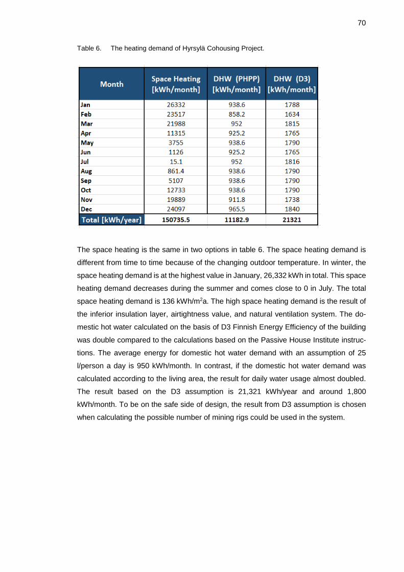
70
Table 6. The heating demand of Hyrsylä Cohousing Project.
The space heating is the same in two options in table 6. The space heating demand is
different from time to time because of the changing outdoor temperature. In winter, the
space heating demand is at the highest value in January, 26,332 kWh in total. This space
heating demand decreases during the summer and comes close to 0 in July. The total
space heating demand is 136 kWh/m2a. The high space heating demand is the result of
the inferior insulation layer, airtightness value, and natural ventilation system. The do-
mestic hot water calculated on the basis of D3 Finnish Energy Efficiency of the building
was double compared to the calculations based on the Passive House Institute instruc-
tions. The average energy for domestic hot water demand with an assumption of 25
l/person a day is 950 kWh/month. In contrast, if the domestic hot water demand was
calculated according to the living area, the result for daily water usage almost doubled.
The result based on the D3 assumption is 21,321 kWh/year and around 1,800
kWh/month. To be on the safe side of design, the result from D3 assumption is chosen
when calculating the possible number of mining rigs could be used in the system.

71
7.2 Heating Supply from Mining Rig
In this chapter, the heating production of a mining rig is investigated, and heat energy
output from a heat pump which takes the heat from the mining rig is calculated. At first,
the real COP of the heat pump needs to be calculated according to Carnot theory. Then,
the energy output can be calculated according to the COP value. The heat energy output
then increases according to the quantities of the rig used in the system. After that, the
result can be compared to the demand. Figure 30 below indicates the COP of the heat
pump, working in a room temperature of 35 degrees Celsius.
Figure 30. Heat pump COP
Figure 30 shows the changing COP value when the indoor temperature of the mining
room changes. The maximum temperature for the mining room is 40 degrees Celsius.
However, with this temperature, overheating can occur in the mining rig and this may
lead to system breakout. To be on the safe side, the temperature of 35 degrees Celsius
is used to calculate the COP of the heat pump and to find the heat energy output. As
mentioned in figure 30, the COP of 35 degrees Celsius is 6.6, the highest COP of any
heat pump in the market. With the COP result, the energy output of the heat pump can
be calculated, it is indicated in figure 31 below.

72
Figure 31. Heat Energy production from mining rigs.
In figure 31, the production of one mining rig is 1,135.26 kWh/month. If the size of the
mining rig is increased, the heat production increases also according to the number of
rigs. With this information, the heat energy supply and demand can be met. Also, with
the heating demand of the project, the number of mining rigs can be calculated so that
there is no waste heat energy, thus creating an energy efficient system. The next chapter
presents the results and discusses if the project should be dedicated to mining produc-
tion and be allowed to create more waste heat energy than its needed.
7.3 The Final Result and Discussion
After finding the supply and demand, the last step is to match them together and com-
plete the system for this project. The heat energy from the mining production is constant
and available at the same level all year around. The space heating demand changes
according to the ambient temperature outside. There is no demand in the summer, and
a huge demand in the winter. The domestic hot water demand is constant and depends
on the habits of the resident. However, it can be considered a constant value throughout
the year. The table 7 below shows three values for heating energy production in this
project and figure 32 shows the heating demand of domestic hot water and space heat-
ing, and the heat production of mining rigs.

73
Table 7. The heating demand and heat production of mining rigs.
As described in table 7, to cover the domestic hot water demand of the project, only two
mining rigs (Antminer S9) could be used, and they are enough to generate heat and
money at the same time. If the mining system use only one Antminer S9 device, the heat
production can be around 1043 kWh/month. The electric usage here indicates the elec-
tric consumption of heat pump. For one unit Antminer S9, to generate 1043kWh heat
energy in one month, the heat pump consumes 2.61 kWh/day. Figure 32 shows the
heating demand of Hyrsylän project during a year. The demand for domestic hot water,
calculated on the basis of D3, is 1,800 kWh/month, and the heat energy supply for two
mining rigs is 2,270 kWh/month. There is a little extra energy from the production which
could be considered to be heat loss through the distribution and cylinder. To cover the
peak demand of the space heating, the number of mining rigs can be up to 20 mining
rigs. However, there would be a massive problem with extra heat energy from the mining
process in the summer.
Figure 32. The Heating Demand of project and the production of mining cryptocurrency.

74
If the Hyrsylä project wants to use more mining rigs to also cover the space heating
demand in the winter, there is a possible solution to solve the problems. First, the pro-
duction could be reduced in the summer and increased to a 100 % capacity in the winter.
Secondly, the extra heat energy could be used for another purpose in the summer, for
example, for the dry laundry room, for heating the swimming pool, or the basement to
remove mold, etc. The substantial amount of heat from the mining rig creates always
problems and the system needs to be designed carefully and wisely to be energy effi-
cient.

75
8 Conclusion
In conclusion, the use of waste heat from cryptocurrency mining integrated into building
service system was clarified based on theoretical research and simulation. This thesis
provides primary knowledge about the mining process, heating systems, and about how
to combine them in a practical case. The heat from mining rigs was tested and proved to
be usable in building services systems, making the building more sustainable while guar-
anteeing passive income for the owners.
The thesis contains many unfamiliar concepts for typical businessman to invest in. The
first is the current status of the Finnish heating market. Various energy sources that pro-
duces heat are listed. Furthermore, it is also demonstrated that heating energy is mostly
used almost for space heating and domestic hot water. Moreover, the featured methods
of heating are discussed were illustrated. Especially heat pumps, mainly because they
were considered the most suitable way to collect and reuse waste heat.
Secondly, the cryptocurrency concept was explained in detail. In addiontion, its mining
process was shown to be a process where hardware could not only generate digital cur-
rencies but also waste heat. Additionally, its challenges and future were analyzed to
show the worth of recycling waste heat. Cryptocurrency mining is an excellent chance to
get rich quickly. However, at the same time, cryptocurrency included high financial risks,
high cost, and environmental impacts. If waste heat from the mining process is recycled
to the HVAC system of a building, the cost and environment of harm would be minimized.
Thirdly, the cooling methods and heat recycling idea were studied. The same cooling
technology could be applied to mining rigs as to traditional data centers because they
use the same computer technology, operate the whole time and emit enormous amounts
of waste heat. Additionally, the authors of this thesis were not the pioneers in the idea of
recycling waste heat, mining radiators and mining waste heat removal by hydraulics.
However, innovative ideas were presented in the thesis, such as combining waste heat
with a heat pump and a compact unit for domestic hot water, space heating for the whole
building and cooling for the mining rigs. The idea to combine mining rigs with a heat
pump with the containment method to heat the domestic water was chosen because the
heating demand was constant so that there was no period of overheating.

76
Fourthly, the results of the heating demand of and production for a real building were
simulated. The comparison between the heating demand and heating production was
demonstrated by a chart that considered the number of mining rigs feasible to cover the
heating demand for domestic hot water and space heating. The simulation gave the re-
sult that two pieces of mining hardware Antminer S9 would be enough to meet the heat-
ing demand of the domestic hot water of the building for one year. To apply the waste
heat for space heating, twenty mining devices were required, but then, overheating would
happen in the summer. The approaches suggested to handle this problem were either
to heat other sources, such as a basement, laundry, swimming pool or just directly blow-
ing the heat out to the environment when the condenser was heating the water tank on
the roof.
Several applications could be based on this thesis. The architect and miners of the
Hyrsylä project could use this thesis for their mining center installation and for making a
final decision on pursuing their mining purpose. The cooling methods, heat pump meth-
ods and a variety of mining rigs have been analyzed in this thesis. Furthermore, the
amount of heat production and electricity consumption by the heat pump were also
calculated so that the return on investment or the financial plan could be established.
The life cycle cost of the whole project was not calculated in this thesis because it would
involve to the cryptocurrency revenue which is very unstable and fluctuates; it is clear
that even financial experts cannot predict the trend of the market precisely these days.
However, the data about energy and mining hardware calculation in this thesis could be
used combined with the assumption to make a full financial plan for a mining center with
price in details.

77
References
Aibeo Pedro. Svartsa Skola Cohousing [Online]; 2017. URL: http://svartsaskola.com/2017/10/29/looking-for-a-new-team-for-cohousing/ Accessed 10 March 2018.
Alexa. Traffic Statistics [Online]. Alexa; 2014. URL: https://www.alexa.com/siteinfo/coinmarketcap.com Accessed 10 March 2018.
Bitcoin Mining. Bitcoin Mining Hardware Guide [Online]. Bitcoin Mining; 2017. URL: https://www.bitcoinmining.com/bitcoin-mining-hardware/ Accessed 23 March 2018.
Bitcoin Mining. Frequently Asked Question: Bitcoin Mining [Online]. Bitcoin Mining; 2017. URL: https://www.bitcoinmining.com/faq/ Accessed 23 March 2018.
BitFury Group. Proof of Stake versus Proof of Work. Washington DC, Bitfury Group Limited; 2015.
Bitman. Shop of Bitman [Online]. Bitman; 2013. URL: http://shop.bitmain.com/product/main?lang=en Accessed 23 March 2018.
Bitshopper.de. High performance USB Stick Miner GekkoScience Compac 8-16 GH/s (23 GH/s max.) [Online]. Bitshopper.de; 2017. URL: http://www.bitshopper.de/shop/sha-256-miner-en/gekkoscience-compac/?lang=en Accessed 23 March 2018.
Blockchain Luxembourg. Blockchain [Online]. Blockchain Luxembourg; 2017. URL: https://blockchain.info/ Accessed 11 March 2018.
Coinmarketcap. Cryptocurrency Market Capitalizations. [Online]. Coinmarketcap; 2013. URL: https://coinmarketcap.com/all/views/all/ Accessed 10 March 2018.
Collie, M. J. Heat pump technology for saving energy. Noyes Data Corporation; 1979.
Committee On Payments and Market Infrastructures. Digital currencies. Bank For International Settlements; November 2015.

78
Danfoss, 2018. 8 Steps - Control of heating system [Online]. Danfoss; 2018. URL: http://heating.danfoss.com/pcmfiles/1/master/other_files/library/heating_book/ chapter1.pdf Accessed 10 March 2018.
Davies, G. A History of Money - From Ancient Times to the Present Day. 3rd edition. Cardiff: University of Wales Press; 2002.
Alakangas, E., Heinimö, J., Ranta, T. and Karhunen, A. Efficient and environmentally friendly biomass heating. Helsinki, Technical Research Centre of Finland; 2008.
Eldredge, B. This tiny house is heated by bitcoin mining [Online]. Curbed; 2017. URL: https://www.curbed.com/2017/11/9/16619032/bitcoin-mining-heat-homes-siberia-russia Accessed 21 March 2018.
EN 13141-7. Ventilation for buildings. Performance testing of components/products for residential ventilation. Performance testing of a mechanical supply and exhaust ventilation units (including heat recovery) for mechanical ventilation systems intended for single fa. BSI; 2011.
EQUA Simulation Technology Group. IDA ICE Retting Started. [Online]. EQUA; 2016. URL: http://www.equaonline.com/iceuser/pdf/ICE47GettingStartedEng.pdf Accessed 12 April 2018.
European Banking Authority. EBA Opinion on 'virtual currencies'. [Online]. EBA; 2014. URL: http://www.eba.europa.eu/documents/10180/657547/EBA-Op-2014-08+Opinion+on+Virtual+Currencies.pdf Accessed 9th March 2018.
Evans, T. The Different Technologies for Cooling Data Centres. Schneider Electric; 2012.
Feist Wolfgang. Empfehlungen zur Lüftungsstrategie, in Protokollband 23 des Ar-beitskreises kostengünstige Passivhäuser, Passivhaus Institut, 2003
Finnish Energy Industries. Correct Use of District Heat. Helsinki. Printing Libris Oy; 2007.
Finnish Forest Association. Finnish Forest Resources [Online]. 2016. URL: https://www.smy.fi/en/forest-fi/forest-facts/finnish-forests-resources/ Accessed 9th March 2018.
Goelzer, B. Hansen, C. H. and Sehrndt, G. A. Occupational exposure to noise: evaluation, prevention, and control [report]. Geneva. World Health Organization; 2001.
Hansen Morten, Jein Anna, Hayes Sandra, and Bateman Patrick. English Handbook for Wood Pellet Combustion [Online]. 2009

79
URL: https://pelletsatlas.info/wp-content/uploads/2015/09/Handbook_English_dis-claimer.pdf Accessed 10 March 2018.
Hileman, G. & Rauchs, M. Global Crytocurrency Benchmarking Study. Cambridge, Cambridge Centre for Alternative Finance; 2017.
Hu, K. Bitcoin miner: 'I haven't paid for heat in three years' [Online]. Yahoo; 2017. URL: https://finance.yahoo.com/news/bitcoin-miner-havent-paid-heat-three-years-143714695.html Accessed 21 March 2018.
Hyrsylä. (2018). Taustat [Online]. Hyrsylä; 2018. URL: http://www.hyrsyla.fi/taustat/ Accessed March 15, 2018.
ICObench. ICO bench [Online]. ICObench; 2017. URL: https://icobench.com/icos/crypto currency Accessed 10 March 2018.
Insinööritoimisto Airkos. Hyrsylä koulu rakenteiden mikrobinäytteet. Lohja, Insinööritoimisto AIRKOS Oy; 2015.
Jevons, W. Money and the Mechanism of Exchange. London; 1910.
Jokisalo, J. Technical improvement of energy performance of Finnish houses. Helsinki, Aalto University; 2013.
Khatwani, S. What Is A Masternode And How Is It Useful For Cryptocoin Investors [Online]. Coinsutra; 2018. URL: https://coinsutra.com/masternodes/ Accessed 11 March 2018.
Khemarattana, C. Cryptocurrency Mining. Bangkok, Fintech; 2017.
Klass, D. L. Biomass for Renewable Energy and Fuels. Encyclopedia of Energy 2004; 1: 193-204.
Kou Guangxiao, Wang Hanqing, and Zhou Jiemin. Maximum thermal efficiency of con-
densing boiler [Online]. 2018.
URL: http://www.inive.org/members_area/medias/pdf/Inive %5CIAQVEC2007 %5CKou_2.pdf Accessed 9th March 2018.
Langland, T. & Skordal, K. K. Mining Bitcoins using a Heterogeneous. Trondheim, Norwegian University of Science and Technology; 2015.

80
Mardiana A., Riffat S.B. Review on Physical and Performance Parameters of Heat. Renew. a. Sust. Energy Rev 2013; (28): 74–190.
Fehrm Mats, Reiners Wilhelm and Ungemach Matthias. Exhaust air heat recovery in buildings. International Journal of Refrigeration 2002; 25: 439–449.
Natural Resource Canada. Heating and Cooling with a Heat Pump. Gatineau QC; 2004.
Nibe. NIBE Exhaust air A new generation of heat pumps. Nibeonline; 2018 [Online] URL: http://www.nibeonline.com/pdf/439028-11.pdf Accessed 11 March 2018.
Heat recovery ventilation guide for houses 2015. Burnaby, British Columbia and Canada, Homeowner Protection Office and Branch of BC Housing; 2015.
Passipedia. What is Passive House [Online]. 2018 URL: https://passipedia.org/basics/what_is_a_passive_house Accessed 11 March 2018.
Passive House Institute. This will only work in a Passive House: Heating with nothing other than fresh air [Online]. 2018. URL: https://passiv.de/former_conferences/Passive_House_E/compact_system_pas-sive_house.htm Accessed 11 March 2018.
Perper, R. Iceland may use more electricity to mine bitcoins than it does to power all of its houses this year [Online]. Business Insider; 2018. URL: http://nordic.businessinsider.com/iceland-bitcoin-mines-are-booming-2018-2 Accessed 23 March 2018.
Pippuri, P. Heating mode choices of Finnish households and the Energy Paradox. Helsinki, Aalto University; 2012
Powers, J. M. Lecture Notes on Thermodynamics: Chapter 10: Cycles. University of Notre Dame; 2013.
Price, R. Someone in 2010 bought 2 pizzas with 10,000 bitcoins — which today would be worth $100 million. [Online]. Businessinsider; 2017. URL: http://www.businessinsider.com/bitcoin-pizza-10000-100-million-2017-11?r=UK&IR=T&IR=T Accessed 11 March 2018.
Quarnot. QC.1 The first crypto heater [Online]. 2018 URL: https://www.qarnot.com/crypto-heater_qc1/ Accessed 11 March 2018.

81
Rasmussen, N. The Different Types of Air Distribution for IT Environments. Schneider Electric; 2017.
Rosic, A. Proof of Work vs Proof of Stake: Basic Mining Guide [Online]. Blockgeeks; 2017. URL: https://blockgeeks.com/guides/proof-of-work-vs-proof-of-stake/ Accessed 11 March 2018.
Rosic, A. What is Blockchain Technology? A Step-by-Step Guide For Beginners. [Online]. 2017. URL: https://blockgeeks.com/guides/what-is-blockchain-technology/ Accessed 11th March 2018.
Guerra Santin, Olivia; Itard, Laure and Visscher, Henk. The effect of occupancy and building characteristic on energy use for space and water heating in Dutch residential stock. Energy and Building. Volume 41, Issue 11, November 2009. p. 1223-1232.
Statistic Finland. Energy consumption in households 2016. Helsinki, Official Statistic of Finland; 2017.
Statistic Finland. Finland in Figures 2017. Helsinki, Statistic Finland; 2017.
Sterry, D. R. Introduction to Bitcoin Mining - A Guide For Gamers, Geeks, and Everyone Else [Online]. CoinDL.com; 2012. URL: http://euro.ecom.cmu.edu/resources/elibrary/epay/IntroductiontoBitcoinMining Sterry.pdf Accessed 11 March 2018.
Sulpu. Heat Pump Investments up to Half a Billion a year in Finland. Helsinki, Sulpu; 2018.
Tuwiner, J. Bitcoin Mining Hardware ASICs [Online]. Buybitcoinworldwide; 2018 URL: https://www.buybitcoinworldwide.com/mining/hardware/ Accessed 23 March 2018.
UBS AG and UBS Financial Services Inc. Cryptocurrencies - Beneath the bubble [report]. The United States, Chief Investment Office Americas, Wealth Management; 2017.
Zottl, A., Nordman, R. & Miara, M. Benchmarking method of seasonal performance [report]. SEPEMO; 2012.

Appendix 1
1 (6)
Appendix 1. Architectural Drawing of Hyrsylä Co-Housing Project

Appendix 1
2 (6)

Appendix 1
3 (6)

Appendix 1
4 (6)

Appendix 1
5 (6)

Appendix 1
6 (6)

Appendix 2
1 (2)
Appendix 2. Heating and Energy Report for Hyrsylä Co-Housing Project

Appendix 2
2 (2)