reverse engineering based methodology for redesigning...
TRANSCRIPT

World Journal of Engineering and Technology, 2016, 4, 206-212 http://www.scirp.org/journal/wjet
ISSN Online: 2331-4249 ISSN Print: 2331-4222
DOI: 10.4236/wjet.2016.43D025 October 20, 2016
Reverse Engineering Based Methodology for Redesigning Contour Milling Tools
A. P. Valerga*, M. Batista, J. Salguero, A. Gomez-Parra, M. Marcos
Mechanical Engineering and Industrial Design Department, Faculty of Engineering, University of Cadiz, Puerto Real, Cádiz, Spain
Abstract Reverse Engineering (RE) involves the use of techniques aimed to retrieve informa-tion about manufactured products, not only regarding geometries, but also materials and functionality. Today, even if several RE techniques are known, many of them still leave the object unusable to analyze. Nevertheless, other alternatives to this problem allows for obtaining a Digital or Virtual Model (VM) via the three-dimen- sional scanning. Getting the VM of an item, via scanning or not, can offer many pos-sibilities to digital analysis (FEM). Furthermore, starting from VM, it is possible to achieve the physical reproduction of an element, part or workpiece—in the same or different materials—using Additive Manufacturing (AM) technologies. This enables to improve the product through a redesign process. In this paper, a RE based me-thodology is proposed for redesigning a tool for contour milling, after comparing different microscopy based techniques, 3D-Scanner tools and CAD-CAGD utilities for generating a Virtual Model of the newly designed mill.
Keywords Reverse Engineering, Cutting Tools, Simulation, 3D Scanning, Modelling
1. Introduction
Machining processes are the most commonly used manufacturing process in the cur-rent aerospace industry.
Machining processes are central in the manufacture of parts and increasing the effi-ciency of these processes would be achieved higher profitability of the manufacturing process thereof. These processes are also critical in the manufacture of certain compo-nents as required certifications for aerospace industry. This makes the manufacturing process of these components cannot be modified freely which leads to conduct a con-tinuous process improvement is difficult and profitability may stall. However, there are
How to cite this paper: Valerga, A.P., Ba- tista, M., Salguero, J., Gomez-Parra, A. and Marcos, M. (2016) Reverse Engineering Based Methodology for Redesigning Contour Mil- ling Tools. World Journal of Engineering and Technology, 4, 206-212. http://dx.doi.org/10.4236/wjet.2016.43D025 Received: September 24, 2016 Accepted: October 13, 2016 Published: October 20, 2016

A. P. Valerga et al.
207
certain elements that can be modified to improve the process such as tools or cutting parameters used. In this context, an improved tool and a correct selection of cutting parameters could have a decisive impact on the profitability of the process [1].
However, it is usually necessary to perform a large number of experimental tests to find the optimal tool geometry and process conditions. Using simulations can signifi-cantly reduce the number of experimental tests, causing a reduction in cost and time [1]-[3].
With these simulations it is possible to do tests to check how certain geometric factors of the tools affect their behavior and then select the best. Also it is possible to study how the parameters affect cutting efficiency of the tool and select the ideal pa-rameters.
However it is necessary to have a virtual model of the tool to perform these studies, and this requires working with geometric accurate tool but many manufacturers do not provide this information easily, so it is necessary to establish a methodology to obtain this data from a given tool.
Today, even if several RE techniques are known, many of them still leave the object unusable to analyze. Nevertheless, other alternatives to this problem allows for obtain-ing a Digital or Virtual Model (VM) via the three-dimensional scanning [4]-[6].
This paper presents a comparison between various redesign methodologies for ob-taining a Virtual Model of peripheral machining tools using Reverse Engineering. One of them involves the digitizing by three-dimensional scanning obtaining a 3D point cloud. The other exposed methodology is based on obtaining a 3D model from an or-thogonal cutting section which awards a 2D point cloud.
2. Methodological Procedure
This study is based on the comparison of two experimental methods in order to obtain the virtual model of a cutting tool. The first one is related with a traditional metallo-graphic method. The second is using new scanning techniques. The final result of both methods is a VM that can be processed.
The phases carried out until obtaining the virtual model are shown in Figure 1. A common flowchart is developed in both methodologies.
2.1. Geometry Data Acquisition
A KENDU tool for contour milling has been taken as reference tool. It is necessary to know geometric parameters for modeling the original tool.
Figure 1. Methodological procedure.
SimplifygeometryMethod 1
Metallographic procedureCross section measurement
Starting element
Datatreatment
VirtualModel
3D scanAligning pointsMethod 2
Meshtreatment
Digitizing

A. P. Valerga et al.
208
The first method performs two-stage data acquisition tool: metallographic procedure and cross section measurement.The metallographic procedure mainly consists of ob-taining a representative cross section of the tool through a transversal cutting of the tool. WEDM technology has been used for obtaining the section of the tool causing minimal deformations on it.
Tool sectioned sample is prepared according to the metallographic protocol. The sample is embedded within a polymer in pellet form and subsequently a grinding proc-ess and polished is carried out to obtain a specular surface. Then the measurement of the cross section of the sample is developed. With a 3D optical measurement equip-ment, a point cloud contour section of the tool it is generated, Figure 2. This point cloud is stored in .IGS format to post-process the information by a specific design soft-ware.
In the second method, a more direct way is developed to the data acquisition. In this case, the scanning is performed by a peripheral 3D scanner. The data set obtained from scanning is called 3D cloud points and describes the physical object in a three dimen-sional space. The conversion of data acquired by a scanning system to a CAD model is a complex but direct system, unlike the previous metallographic procedure performed or a model created from scratch, which often requires numerous revisions. This con-version can be performed using a specific digitization program of each scanner or with numerous CAD software. However, there are different kinds of scanning and not all of them offer the same results [7].
It has been used three techniques to capture the geometric information of the tool: structured light, laser triangulation and laser phase difference. Although all these me-thods are different in many features and the results obtained, the concept and scanning stages are similar and involves three major steps prior to data processing: exploration (acquisition points), alignment (manual or automatic) and fusion (convert into a solid), Figure 3. Nevertheless, the structured light system has been selected inasmuch as it of-fers the best quality-cost ratio of the 3 proposals. This method consists of projecting a light pattern on an object and analyze the pattern deformation produced by the scene geometry (scanning).
(a) (b) (c)
Figure 2. (a) Transversal tool sections obtained by WEDM cutting. (b) Section sample after be-ing prepared for metallographical inspection. (c) Optical 3D measurement of section sample.

A. P. Valerga et al.
209
(a) (b) (c)
Figure 3. CAD operations: (a) Exploration; (b) Alignment; (c) Fusion.
2.2. Data Treatment
From the point cloud, the object must be modelled. In the first case the point cloud is projected onto an XY plane created. It is containing geometric information of the cross section of the tool. From it, a perpendicular line is defined embodying the height of the solid. With some geometric data provided by the manufacturer as the diameter and pitch, the tool can be defined. The virtual model obtained from a section of the tool al-lows the possibility of being configured, because it is done with minimal design enti-ties. Possessing a parameterized model facilitates the ability to make changes in the geometry of the tool. Thus, it is possible to achieve an optimized tool changing the he-lix, incidence, and detachment angles, tip radius, etc.
This procedure could be performed similarly in the second method. However, there is lesser point density in a section, since the scan capture a limited number of them. This originates dark areas in certain parts. For this reason, it is preferable to perform a mesh treatment. This treatment consists basically to convert those points into polygons and perform a closure of the surface. This procedure is quite complex and tedious to be applied in industrial environments. The mesh must be closed to become the virtual model.
3. Results
The main difference between the methodologies described is the conservation of the tool. A cross section is needed in the methodology 1 to obtain a section, so the tool be-comes unusable. However, the methodology 2 uses a conservative procedure. The tool is not damaged, so that it can be subsequently used to perform various experimental tests. Furthermore, from the methodology 1 it is only possible to obtain a point cloud of a given cross section, unlike in the second case, where a point cloud of the entire tool is obtained, so that the virtual model obtained is three-dimensional, Figure 4.
However, if the density of points in this studied section is analysed, it will be very different in each method. On one hand, in the method 1, an easily configurable homo-geneous section is obtained. A theoretical model is obtained because the analysed sec-tion is extruded in a perpendicular to the plane direction. In this case, it is possible to

A. P. Valerga et al.
210
(a) (b)
Figure 4. Example of a figure caption. parameterize geometry to perform a theoretical model of the section, built with mini-mal design entities. To parameterize geometry. Therefore, the redesign of the tool is easier.
However, in the other process, although more points you get, they are not distributed homogeneously due to the dark areas that the camera scanner does not reach so easily. Thus the overall definition of the tools in the cutting angle and evacuation channels are limited by this technique [8].
To solve this problem it is necessary to arrange a second equipment oriented such that the image acquisition was similar to that provided in the other equipment but from a different angle. In addition, tools with less than 8 mm nominal diameter, provide more inaccurate results by 3D scanner. This problem can be solved by coating the sur-face, or with the use of a higher-resolution equipment.
Finally, these methodologies are extrapolated to other cutting tools geometries in different machining processes. However, for tools with tip complex geometry, it is eas-ier to obtain the Virtual Model by the methodology 2. To apply the methodology 1, would be also necessary to carry out a study of all the geometric parameters of the tip tool arranged in different planes in space.
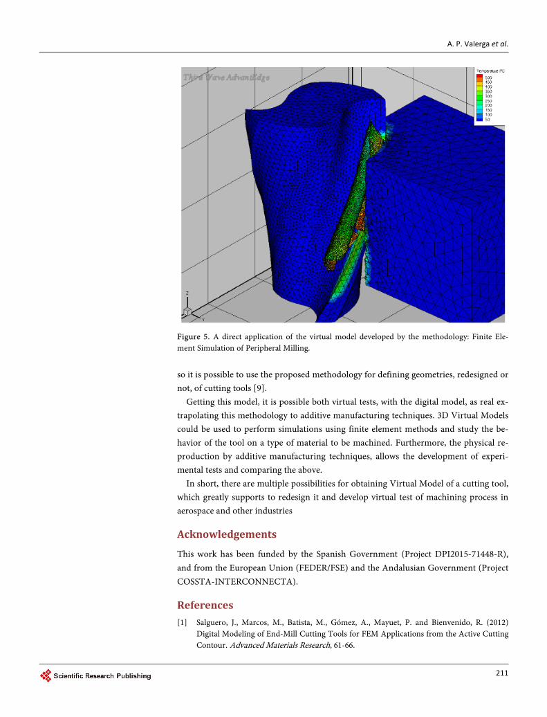
FEM simulations for the most suitable machining parameters can be performed with either model, Figure 5.
4. Conclusions
The methods described in this paper provides many applications for redesigning and manufacturing items. Depending on the type of piece to analyse, the available budget and the target for this model, it will be necessary to invest some time prior to the de-velopment of a methodology. In this case, two very different methodologies for obtain-ing Virtual Model of a cutting tool, in particular a contour tool, have been proposed.
These methodologies have been compared in various aspects and the advantages and disadvantages of each one have been studied.
The multiple possibilities offered by obtaining a Virtual Model for redesigning cut-ting tools have been mentioned. Including cost reduction and more efficient improve-ment in less time. Thus, some measurements have been performed in the digital model,
A. P. Valerga et al.
211
Figure 5. A direct application of the virtual model developed by the methodology: Finite Ele-ment Simulation of Peripheral Milling. so it is possible to use the proposed methodology for defining geometries, redesigned or not, of cutting tools [9].
Getting this model, it is possible both virtual tests, with the digital model, as real ex-trapolating this methodology to additive manufacturing techniques. 3D Virtual Models could be used to perform simulations using finite element methods and study the be-havior of the tool on a type of material to be machined. Furthermore, the physical re-production by additive manufacturing techniques, allows the development of experi-mental tests and comparing the above.
In short, there are multiple possibilities for obtaining Virtual Model of a cutting tool, which greatly supports to redesign it and develop virtual test of machining process in aerospace and other industries
Acknowledgements
This work has been funded by the Spanish Government (Project DPI2015-71448-R), and from the European Union (FEDER/FSE) and the Andalusian Government (Project COSSTA-INTERCONNECTA).
References [1] Salguero, J., Marcos, M., Batista, M., Gómez, A., Mayuet, P. and Bienvenido, R. (2012)
Digital Modeling of End-Mill Cutting Tools for FEM Applications from the Active Cutting Contour. Advanced Materials Research, 61-66.

A. P. Valerga et al.
212
http://dx.doi.org/10.4028/www.scientific.net/AMR.498.61
[2] das Neves, G.P.S. (2010) Simulaçao Numérica por Elementos Finitos da Maquina gem de Titanio e Suas Ligas. Thesis, Universidad de Aveiro, Portugal.
[3] Ozel, T. and Zeren, E. (2004) Determination of Work Material Flow Stress and Friction for FEA of Machining Using Orthogonal Cutting Tests. Journal of Material Processing Tech-nology, 153, 1019-1025. http://dx.doi.org/10.1016/j.jmatprotec.2004.04.162
[4] Váradya, T., Martin, R.R. and Cox, J. (1997) Reverse Engineering of Geometric Models— An Introduction. Computer Aided Design, 29, 255-268. http://dx.doi.org/10.1016/S0010-4485(96)00054-1
[5] Yea, X., Liu, H., Chen, L., Chen, Z., Pan, X. and Zhang, S. (2008) Reverse Innovative Design —An Integrated Product Design Methodology. Computer Aided Design, 40, 812-827. http://dx.doi.org/10.1016/j.cad.2007.07.006
[6] Stark, R., et al. (2013) Product Analysis Automation for Digital MRO Based on Intelligent 3D Data Acquisition. CIRP Annals-ManufacturingTechnology, 123-126. http://dx.doi.org/10.1016/j.cirp.2013.03.079
[7] Tian, C., Xiaoming, D., Jianming, Z. and Xinjue, Z. (2009) Point-Based Data Analysis for Extracting Parameters of Cutting Tools. Tsinghua Science and Technology, 14, 47-55. http://dx.doi.org/10.1016/S1007-0214(09)70066-5
[8] Fenga, H.Y., Liua, Y. and Xib, F. (2001) Analysis of Digitizing Errors of a Laser Scanning System. Precision Engineering, 25, 185-191. http://dx.doi.org/10.1016/S0141-6359(00)00071-4
[9] Vagovský, J., Buranský, I. and Görög, A. (2015) Evaluation of Measuring Capability of the Optical 3D Scanner. Procedia Engineering, 100, 1198-1206. http://dx.doi.org/10.1016/j.proeng.2015.01.484
Submit or recommend next manuscript to SCIRP and we will provide best service for you:
Accepting pre-submission inquiries through Email, Facebook, LinkedIn, Twitter, etc. A wide selection of journals (inclusive of 9 subjects, more than 200 journals) Providing 24-hour high-quality service User-friendly online submission system Fair and swift peer-review system Efficient typesetting and proofreading procedure Display of the result of downloads and visits, as well as the number of cited articles Maximum dissemination of your research work
Submit your manuscript at: http://papersubmission.scirp.org/ Or contact [email protected]