reverse engineering - carnegie mellon school of …aldrich/courses/654-sp05/... · ·...
TRANSCRIPT
1Reverse EngineeringLiam O’BrienApril 2005
© 2005 by Carnegie Mellon University
Sponsored by the U.S. Department of Defense© 2005 by Carnegie Mellon University
Version 1.0 page 1
Pittsburgh, PA 15213-3890
Reverse Engineering
Liam O’Brien
© 2005 by Carnegie Mellon University Version 1.0 page 2
Outline
This lecture will cover:
•Definition, Activities •Supporting Techniques
- Static Analysis- Program Slicing- Program Plans
•Reverse Engineering Tools
2Reverse EngineeringLiam O’BrienApril 2005
© 2005 by Carnegie Mellon University
© 2005 by Carnegie Mellon University Version 1.0 page 3
Reverse Engineering
Reverse Engineering supports understanding of a system through identification of the components or artifacts of the system, discovering relationships between them and generating abstractions of that information.
The goal of reverse engineering is not to alter the system in any way.
Reference:E.J. Chikofsky and J.H. Cross, "Reverse Engineering and Design Recovery - A Taxonomy," IEEE Software, Jan. 1990, 13-17.
© 2005 by Carnegie Mellon University Version 1.0 page 4
Reverse Engineering Activities
The three main Reverse Engineering activities:
•Data Gathering•Knowledge Organization•Information Exploration

3Reverse EngineeringLiam O’BrienApril 2005
© 2005 by Carnegie Mellon University
© 2005 by Carnegie Mellon University Version 1.0 page 5
Data Gathering
Raw data is used to identify a system’s artifacts and relationships
Techniques include:
•Static source code analysis (parsing)•Dynamic Analysis (profiling)•Informal extraction (interviewing)
© 2005 by Carnegie Mellon University Version 1.0 page 6
Knowledge Organization
Goals of Knowledge Organization are:•Efficient storage of knowledge•Permit automated analysis •Reflect user’s perspective
Classical data models•Hierarchical •Network•Relational

4Reverse EngineeringLiam O’BrienApril 2005
© 2005 by Carnegie Mellon University
© 2005 by Carnegie Mellon University Version 1.0 page 7
Abstraction Mechanisms
Abstraction: Selective emphasis on detail
Common Mechanisms:•Classification•Aggregation•Generalization
Conceptual Modeling
© 2005 by Carnegie Mellon University Version 1.0 page 8
Information Exploration
Probably the most important activity:•Data gathering: necessary to begin•Knowledge organization: structure model•Information Exploration: understanding
Composite Activities:•Navigation •Analysis •Presentation
5Reverse EngineeringLiam O’BrienApril 2005
© 2005 by Carnegie Mellon University
© 2005 by Carnegie Mellon University Version 1.0 page 9
Navigation
Traverse non-linear information structures
Link relationships:•Component hierarchies•Inheritances•Control and data flow
Hypotheses postulation ? exploration
© 2005 by Carnegie Mellon University Version 1.0 page 10
Analysis
Extracts and derives information not explicitly available from data gathering
Traditional metrics
Query mechanisms for pattern matching
6Reverse EngineeringLiam O’BrienApril 2005
© 2005 by Carnegie Mellon University
© 2005 by Carnegie Mellon University Version 1.0 page 11
Presentation
Spatial and visual data
Descriptive and depictive information
Sense integration: look, feel, etc
Some current issues:• Integration of various visual representations•High flexibility•Context based visualization• Integration of various visualization techniques
© 2005 by Carnegie Mellon University Version 1.0 page 12
Reverse Engineering –Supporting Techniques
Techniques- Static Analysis
– Control Flow– Data Flow
- Program Slicing- Program Plans
7Reverse EngineeringLiam O’BrienApril 2005
© 2005 by Carnegie Mellon University
© 2005 by Carnegie Mellon University Version 1.0 page 13
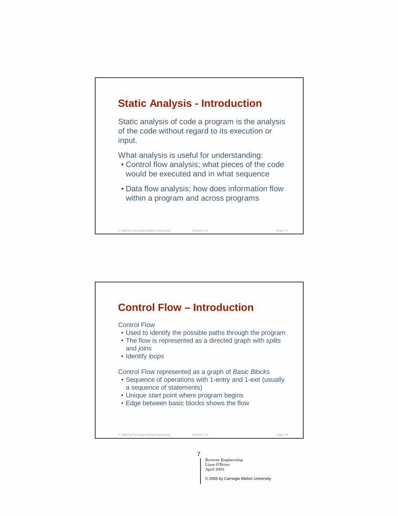
Static Analysis - Introduction
Static analysis of code a program is the analysis of the code without regard to its execution or input.
What analysis is useful for understanding:•Control flow analysis; what pieces of the code
would be executed and in what sequence
•Data flow analysis; how does information flow within a program and across programs
© 2005 by Carnegie Mellon University Version 1.0 page 14
Control Flow – Introduction Control Flow•Used to identify the possible paths through the program•The flow is represented as a directed graph with splits
and joins• Identify loops
Control Flow represented as a graph of Basic Blocks•Sequence of operations with 1-entry and 1-exit (usually
a sequence of statements)•Unique start point where program begins•Edge between basic blocks shows the flow

8Reverse EngineeringLiam O’BrienApril 2005
© 2005 by Carnegie Mellon University
© 2005 by Carnegie Mellon University Version 1.0 page 15
Control Flow – Example
Imagix 4D representation of control flow: http://www.imagix.com
© 2005 by Carnegie Mellon University Version 1.0 page 16
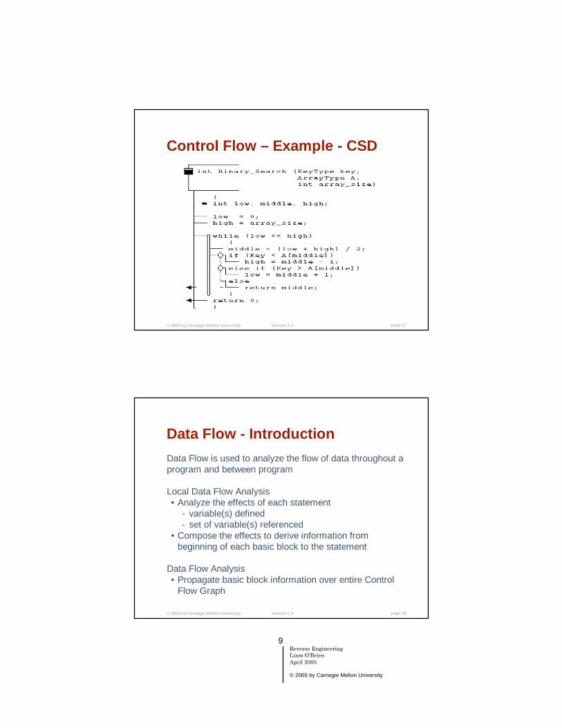
Control Flow – Code View
Another example of visualizing the control flow of a program is using a Control Structure Diagram (CSD). CSD is a algorithmic level graphical representation for software.
The following notations are used:•Sequential flow – straight line• If/The/Else/Switch statements – diamonds•For/While – elongated loop•Loop exit – arrow •Function – open-ended box
The GRASP project at Auburn University http://www.eng.auburn.edu/department/cse/research/grasp/
9Reverse EngineeringLiam O’BrienApril 2005
© 2005 by Carnegie Mellon University
© 2005 by Carnegie Mellon University Version 1.0 page 17
Control Flow – Example - CSD
© 2005 by Carnegie Mellon University Version 1.0 page 18
Data Flow - IntroductionData Flow is used to analyze the flow of data throughout a program and between program
Local Data Flow Analysis •Analyze the effects of each statement
- variable(s) defined- set of variable(s) referenced
•Compose the effects to derive information from beginning of each basic block to the statement
Data Flow Analysis •Propagate basic block information over entire Control
Flow Graph
10Reverse EngineeringLiam O’BrienApril 2005
© 2005 by Carnegie Mellon University
© 2005 by Carnegie Mellon University Version 1.0 page 19
Program Slicing – Introduction - 1
Program Slice definition:
A slice is taken with respect to a slicing criterion <s,v>, which specifies a location (statement s) and a variable (v).
For statement s and variable v, the slice of program P with respect to the slicing criterion <s,v> includes only those statements of P needed to capture the behavior of v at s.
© 2005 by Carnegie Mellon University Version 1.0 page 20
Program Slicing – Introduction - 2
Applications of program slicing:- understanding- debugging- testing- parallelization- integration- software quality- software maintenance- software metrics

11Reverse EngineeringLiam O’BrienApril 2005
© 2005 by Carnegie Mellon University
© 2005 by Carnegie Mellon University Version 1.0 page 21
Program Slicing – Introduction - 3
Program Slicing was first introduced by Weiser. He introduced the concept of an executable backwards staticslice.
- executable - slice is required to be an executable program
- backwards – because of the direction the edges are traversed when computing the slice using a dependence graph
- static because they are computed as the solution to a static analysis problem (without considering the program’s input)
Many applications of program slicing (such as debugging) do not require executable slices.
M. Weiser, Program Slicing, Proceedings of ICSE 1981, 439-449.
© 2005 by Carnegie Mellon University Version 1.0 page 22
Program Slicing – Introduction - 4
Forward slicing (introduced by Horwitz)- “What statements are affected by the value of v at
statement s?”.
Dynamic Slicing (introduced by Korel and Laski)- A slice is computed for a particular fixed input.
S. Horwitz and T. Reps and D. Binkley, Interprocedural Slicing using dependence graphs, Proceedings of the ACM SIGPLAN 88 Conference on Programming Language Design and Implementation, 1988.
B. Korel and J. Laski, Dynamic Program Slicing, Information Processing Letters, 29(3), Oct 1988, 155-163

12Reverse EngineeringLiam O’BrienApril 2005
© 2005 by Carnegie Mellon University
© 2005 by Carnegie Mellon University Version 1.0 page 23
Program Slicing – Flow Graphs - 1
Slicing of a flow graph is a two-step process:1. Compute the data flow information2. Use this information to extract a slice
To obtain the data flow information for statement n we first obtain:- REF(n) – the set of variables that are referenced in
n- DEF(n) – the set of variables defined (given a
value) in n
The data flow information is the set of relevant variables at each node n.
© 2005 by Carnegie Mellon University Version 1.0 page 24
Program Slicing – Flow Graphs - 2
For the slice with respect to <s,v> the relevant set for each node contains the variables whose values transitively affect the computation of v at s.
A statement n is in the slice if it assigns a value to a variable relevant at n and the slice taken with respect to any predicate node that directly controls n’s execution.

13Reverse EngineeringLiam O’BrienApril 2005
© 2005 by Carnegie Mellon University
© 2005 by Carnegie Mellon University Version 1.0 page 25
Program Slicing – Flow Graphs - 3
Relevant sets for the slice taken with respect to <n,v> are computed as follows:
1. Initialize all relevant sets to the empty set.2. Insert v into relevant(n).3. For m, n’s immediate predecessor, assign
relevant(m) the value (relevant(n) –DEF(m)) ? (REF(m) if relevant(n) ? DEF(m) ? {})
4. Working backwards, repeat step 3 for m’s predecessors until ninitial is reached
© 2005 by Carnegie Mellon University Version 1.0 page 26
Program Slicing – Flow Graph - 4
n statement refs(n) defs(n) relevant(n)1 b = 1 b2 c = 2 c b3 d = 3 d b,c4 a = d d a b,c5 d = b + d b,d d b,c6 b = b + 1 b b b,c7 a = b + c b,c a b,c8 print a a a
Slice on <8,a>: {7, 6, 2, 1}

14Reverse EngineeringLiam O’BrienApril 2005
© 2005 by Carnegie Mellon University
© 2005 by Carnegie Mellon University Version 1.0 page 27
Program Slicing – Flow Graph - 5
Slicing with control statements such as:
• IF-THEN-ELSE•Loop Statements
IF-THEN-ELSE -
IF …
…
THEN
…
…Statement following IF
ELSE
relevant
© 2005 by Carnegie Mellon University Version 1.0 page 28
Program Slicing – Flow Graph - 6
n statement refs(n) defs(n) control(n) relevant(n)1 b = 1 b2 c = 2 c b3 d = 3 d b,c4 a = d d a b,c,d5 if (a) then a a,b,c,d6 d = b + d b,d d 5 b,d7 c = b + d b,d c 5 b,d8 else 5 b,c9 b = b + 1 b b 8 b,c10 d = b + 1 b d 8 b,c11 endif b,c12 a = b + c b,c a b,c13 print a a a
Slice on <13,a>: {12, 11, 9, 8, 7, 6, 5, 4, 3, 2, 1} Note: a is included in the relevant set at 5. Otherwise another column.

15Reverse EngineeringLiam O’BrienApril 2005
© 2005 by Carnegie Mellon University
© 2005 by Carnegie Mellon University Version 1.0 page 29
Program Slicing – Flow Graph - 7
Loop Statements:
WHILE …
Statements in Loop
End Loop Statement
relevant
© 2005 by Carnegie Mellon University Version 1.0 page 30
Program Slicing – Flow Graph - 8
Loop Example:
n statement refs(n) defs(n) control(n) relevant(n) relevant(n)Iter 1 Iter 2
1 b = 1 b2 c = 2 c b3 d = 5 d b,c4 a = 3 a b,c5 While (a < 10) a a,b,c a,b,c6 b = b + c b,c b 5 b,c b,c7 c = c + 1 c c 5 b b,c8 a = b b a 5 b b,c9 EndWhile 5 a10 print a a a
Slice on <10,a>: {9, 8, 7, 6, 5, 4, 2, 1}
16Reverse EngineeringLiam O’BrienApril 2005
© 2005 by Carnegie Mellon University
© 2005 by Carnegie Mellon University Version 1.0 page 31
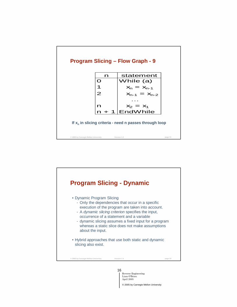
Program Slicing – Flow Graph - 9
n statement0 While (a) 1 xn = xn-1
2 xn-1 = xn-2
…n x2 = x1
n + 1 EndWhile
If xn in slicing criteria - need n passes through loop
© 2005 by Carnegie Mellon University Version 1.0 page 32
Program Slicing - Dynamic
•Dynamic Program Slicing- Only the dependencies that occur in a specific
execution of the program are taken into account.- A dynamic slicing criterion specifies the input,
occurrence of a statement and a variable- dynamic slicing assumes a fixed input for a program
whereas a static slice does not make assumptions about the input.
•Hybrid approaches that use both static and dynamic slicing also exist.

17Reverse EngineeringLiam O’BrienApril 2005
© 2005 by Carnegie Mellon University
© 2005 by Carnegie Mellon University Version 1.0 page 33
Program Slicing – Dynamic e.g. -1n statement1 read(n)2 i := 13 while (i <= n) do4 begin5 if (i mod 2 = 0) then6 x := 177 else8 x := 18;9 i := i + 110 end;11 write(x);
What is dynamic slice with criterion (n = 2, 11, x)?
© 2005 by Carnegie Mellon University Version 1.0 page 34
Program Slicing – Dynamic e.g. -2n statement1 read(n)2 i := 13 while (i <= n) do4 begin5 if (i mod 2 = 0) then6 x := 177 else89 i := i + 110 end;11 write(x);
Dynamic slice with criterion (n=2, 11, x) is entire program without line 8.
Static slice (11, x) is the entire program.

18Reverse EngineeringLiam O’BrienApril 2005
© 2005 by Carnegie Mellon University
© 2005 by Carnegie Mellon University Version 1.0 page 35
Program Plans – Introduction
The goal is to recognize clichés using plans.
A cliché is a pattern that appears frequently in programs (e.g., algorithms, data structures, domain-specific patterns).
A plan is an abstract representation of a cliché.
Representation is at the semantic level rather than at the syntactic level.
© 2005 by Carnegie Mellon University Version 1.0 page 36
Clichés - Examples
Data structure clichés: lists, trees, tables, vectors, matrices
Algorithmic clichés: list, tree, graph traversals; iterators, applicators, manipulators; linear, binary, hash searches; event handler; exception handler
ADT clichés: dictionary, priority queue, heaps

19Reverse EngineeringLiam O’BrienApril 2005
© 2005 by Carnegie Mellon University
© 2005 by Carnegie Mellon University Version 1.0 page 37
Plan RecognitionApproaches:•Top-down: Start with set of goals to be achieved;
determine what plans can achieve these goals; connect these plans to source code patterns.- Problem: Requires detailed advance knowledge
otherwise connection to code is unrealistic •Bottom-up: Start with source code; identify plans that
match source code; infer higher-level goals from these plans.- Problem: Combinatorial explosion of alternatives
•Hybrid: top-down and bottom-up
© 2005 by Carnegie Mellon University Version 1.0 page 38
Plan Recognition – MethodTypical method of plan recognition•An effective (language-independent) program
representation •A translator to transform source text into this program
representation •A library of programming plans representing clichés at
various levels of abstraction •A plan recognizer which parses the program to
recognize plans stored in the library •The result is a tree or lattice with program components
at the leaves, programming plans, and the goals of the program at the root
•Bottom-up program understanding
20Reverse EngineeringLiam O’BrienApril 2005
© 2005 by Carnegie Mellon University
© 2005 by Carnegie Mellon University Version 1.0 page 39
Plan Recognition - IssuesSyntactic variations: Recognizer works on the basis of
structure information only; syntactic variations lead to the same paraphrase, modulo identifiers
Non-contiguousness: Recognizer works with graph structures, can accommodate equivalent sequences of statements
Implementation variations: Similar programs are matched against the same plans, lead to the same paraphrases
Recognition algorithm depends polynomially on size of the program and plan library; graph grammars and graph recognition algorithms deployed
© 2005 by Carnegie Mellon University Version 1.0 page 40
Reverse Engineering - Tools
Types of tools:
• Support tools and utilities• Analysis tools • Reverse Engineering environments• Tool environments for building tools • Integrated forward and reverse engineering
environments

21Reverse EngineeringLiam O’BrienApril 2005
© 2005 by Carnegie Mellon University
© 2005 by Carnegie Mellon University Version 1.0 page 41
Support Tools and Utilities
Support tools and utilities include:
•Parsers•Lexical analyzers•Profilers•ad hoc utilities such as grep and perl
© 2005 by Carnegie Mellon University Version 1.0 page 42
Parsers
Describe the syntax of a language in terms of a grammar (set of production rules and tokens).
Specify what is to be done when certain language constructs are identified.
Usually builds some internal representation of the information that has been obtained.May include the entire set of tokens from a language statement or just selected tokens.

22Reverse EngineeringLiam O’BrienApril 2005
© 2005 by Carnegie Mellon University
© 2005 by Carnegie Mellon University Version 1.0 page 43
Parsers: Grammar example!!in-grammar(‘syntax)grammar CALCproductions
identifier ::= [identifier-name] builds identifier,int-const ::= [integer-value] builds integer-const,add-expr ::= [a-arg1 “+”a-arg2] builds add-expression,mult-expr ::= [m-arg1 “*”m-arg2] builds mult-expression,
precedencefor calc-expression brackets “(“matching “)”
(same-level “+”associativity left),(same-level “*”associativity left)
end
From Refine Programming Language – Reasoning.com
© 2005 by Carnegie Mellon University Version 1.0 page 44
Parsers: Abstract Syntax TreeAn Abstract Syntax Tree (AST) is a representation of the grammar that’s populated by the parser. We parse the expression (3 + (5 * a)) and get the following AST.
add-expression
integer-const
integer-const integer-const3
mult-expression
5 a
a-arg1 a-arg2
m-arg1 m-arg2integer-value
integer-value identifier-name
23Reverse EngineeringLiam O’BrienApril 2005
© 2005 by Carnegie Mellon University
© 2005 by Carnegie Mellon University Version 1.0 page 45
Lexical Analyzers
Identify some set of tokens from a statement within a program.
Examples would be identify “#include”token and the name of the file included.
Useful for extracting call graphs, file dependencies, etc.
© 2005 by Carnegie Mellon University Version 1.0 page 46
Lexical Analyzers vs ParsersWhy do lexical analysis rather than parsing?
Parsing is expensive in terms of time and space
Each programming language requires a new parser to be written (even different versions of the same language require new parsers)
Parsers usually require complete code that can be compiled whereas lexical analyzers do not.
24Reverse EngineeringLiam O’BrienApril 2005
© 2005 by Carnegie Mellon University
© 2005 by Carnegie Mellon University Version 1.0 page 47
ProfilersObtain dynamic (run-time) information about a system.
Some information may not available statically, due to late binding:•polymorphism• function pointers• run-time parameterization
Other ways of obtaining dynamic information?
•Code instrumentation•Use of debugging tool (less efficient)
© 2005 by Carnegie Mellon University Version 1.0 page 48
Analysis Tools
Analysis Tools:•Extract software artifacts including
- control flow graphs- call graphs (structure) - cross-references, - global variables, - types and constants, - pointer analyses (aliasing), - metrics

25Reverse EngineeringLiam O’BrienApril 2005
© 2005 by Carnegie Mellon University
© 2005 by Carnegie Mellon University Version 1.0 page 49
Tool Demo
Understand for C/C++ from Scientific Toolworks, Inc
www.scitools.com
© 2005 by Carnegie Mellon University Version 1.0 page 50
Understanding Environments
Understanding Environments:•Parsing engine, repository, user interface •Store extracted software artifacts in a
repository •Interactive tool to navigate, browse, explore
search, query repository •Syntactic, functional, behavioral pattern
matching and filters •Forming abstract representations
26Reverse EngineeringLiam O’BrienApril 2005
© 2005 by Carnegie Mellon University
© 2005 by Carnegie Mellon University Version 1.0 page 51
Tool Environments
These are environment that contain components that can be combined to build an integrated set of tools.
They may provide certain capabilities and the ability to combine these to generate new tool capability:•parsing and printing of code•control flow analysis•data flow analysis•cross reference
© 2005 by Carnegie Mellon University Version 1.0 page 52
Integrated Environments
Integrated forward and reverse engineering environments •Incorporates analysis and understanding tools •All source information is stored in the
repository to facilitate code generation •Incremental parsing and code generation •Control and data integration
27Reverse EngineeringLiam O’BrienApril 2005
© 2005 by Carnegie Mellon University
© 2005 by Carnegie Mellon University Version 1.0 page 53
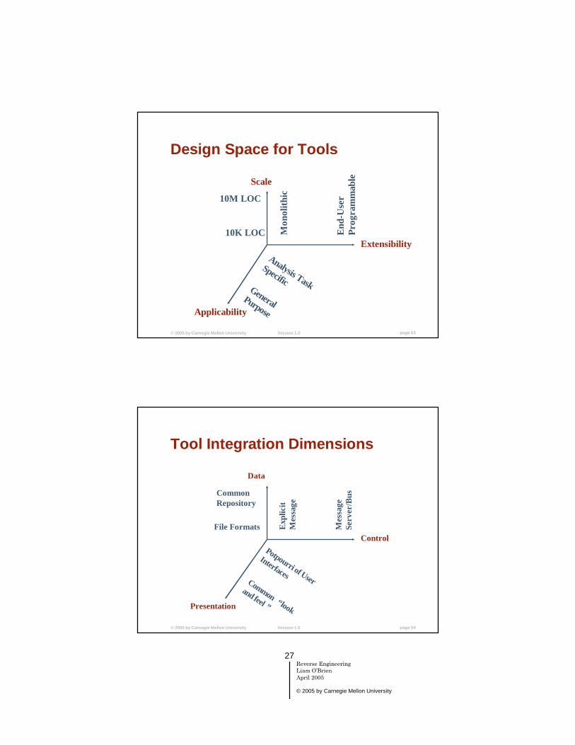
Design Space for Tools
Scale
Extensibility
Applicability
10K LOC
10M LOC
Mon
olith
ic
End
-Use
r Pr
ogra
mm
able
Analysis Task
SpecificGeneral
Purpose
© 2005 by Carnegie Mellon University Version 1.0 page 54
Tool Integration Dimensions
Data
Control
Presentation
File Formats
Common Repository
Exp
licit
Mes
sage
Mes
sage
Se
rver
/Bus
Potpourri of User
InterfacesCommon “look
and feel ”

28Reverse EngineeringLiam O’BrienApril 2005
© 2005 by Carnegie Mellon University
© 2005 by Carnegie Mellon University Version 1.0 page 55
Tool Integration - GXLGXL (Graph eXchange Language) is designed to be a standard exchange format for graphs. It is an XML sublanguage.
This exchange format offers an adaptable and flexible means to support interoperability between graph-based tools such as parsers, control-flow analyzers, program slicers, etc.
Represent the data to be shared as a graph and a schema that describes the graph format.
More information: http://www.gupro.de/GXL/
© 2005 by Carnegie Mellon University Version 1.0 page 56
Information sourcesInformation can be extracted from various sources:
Static- Source code- Makefiles- Documentation- Interviewing
Dynamic- Profiling- Code instrumentation
29Reverse EngineeringLiam O’BrienApril 2005
© 2005 by Carnegie Mellon University
© 2005 by Carnegie Mellon University Version 1.0 page 57
Some Available ToolsThere are lots of tools out there. Examples:
• Imagix 4D (www.imagix.com) - analysis•Rigi (www.rigi.csc.uvic.ca) - analysis•SNiFF+ (www.takefive.com) - analysis tool•Hindsight (www.testersedge.com) - analysis tool•McCabe IQ (www.mccabe.com) - analysis tool•Surgeon’s Assistant (Unravel) - program slicing
(http://www.cs.loyola.edu/~kbg/Surgeon/)•…
Dedicated conference:Working Conference on Reverse Engineering (WCRE)
© 2005 by Carnegie Mellon University Version 1.0 page 58
Summary
In this lecture we talked about Reverse Engineering
Outlined some techniques that support Reverse Engineering
•Static Analysis•Program Slicing•Program Plans
Outlined examples of tools and some of the issues with them.