review of fast ignition hedlp workshop washington michael h. key lawrence livermore national...
Post on 21-Dec-2015
216 views
TRANSCRIPT
Review of Fast Ignition
HEDLP Workshop Washington
Michael H. KeyLawrence Livermore National Laboratory
August 25 to 27, 2008
Work performed under the auspices of the U.S. Department of Energy by the University of California, Lawrence Livermore National Laboratory under
Contract No. W-7405-ENG-48.
UCRL-PRES-
K. Akli2, F. Beg5, R. Betti6, D. S. Clark1, S. N. Chen5, R.R. Freeman2,3
S Hansen1,S.P. Hatchett1, D. Hey2, J.A. King2, A. J. Kemp1, B.F. Lasinski1 B.Langdon1,T. Ma5, A.J. MacKinnon1, D. Meyerhofer10, P.K. Patel1, J. Pasley5 R.B. Stephens4, C. Stoeckl6, M. Foord1, M. Tabak1, W. Theobald6, M. Storm6
R.P.J. Town1, S.C. Wilks1, L. VanWoerkom3, M.S. Wei5, R. Weber3, B. Zhang2
1Lawrence Livermore National Laboratory, Livermore, CA 94550, USA
2Department of Applied Sciences, University of California Davis, CA 95616, USA
3Ohio State University, Columbus Ohio, 43210 USA
4General Atomics, San Diego, CA, 92186, USA
5 University of California, San Diego, San Diego, CA, 92186, USA
6Laboratory of Laser Energetics, University of Rochester, NY, USA
Special thanks for advice and information :
Mike Dunne, Wolfgang Theobald, Javier Honrubia, Hiroshi Azechi,
Riccardo Betti
Acknowledgements
Outline
•Concept of FI •Ignition requirements and gain
•Cone coupled electron FI
•Channel electron FI
•Proton and mid Z ion ignition
•Major integrated experiments
•Summary
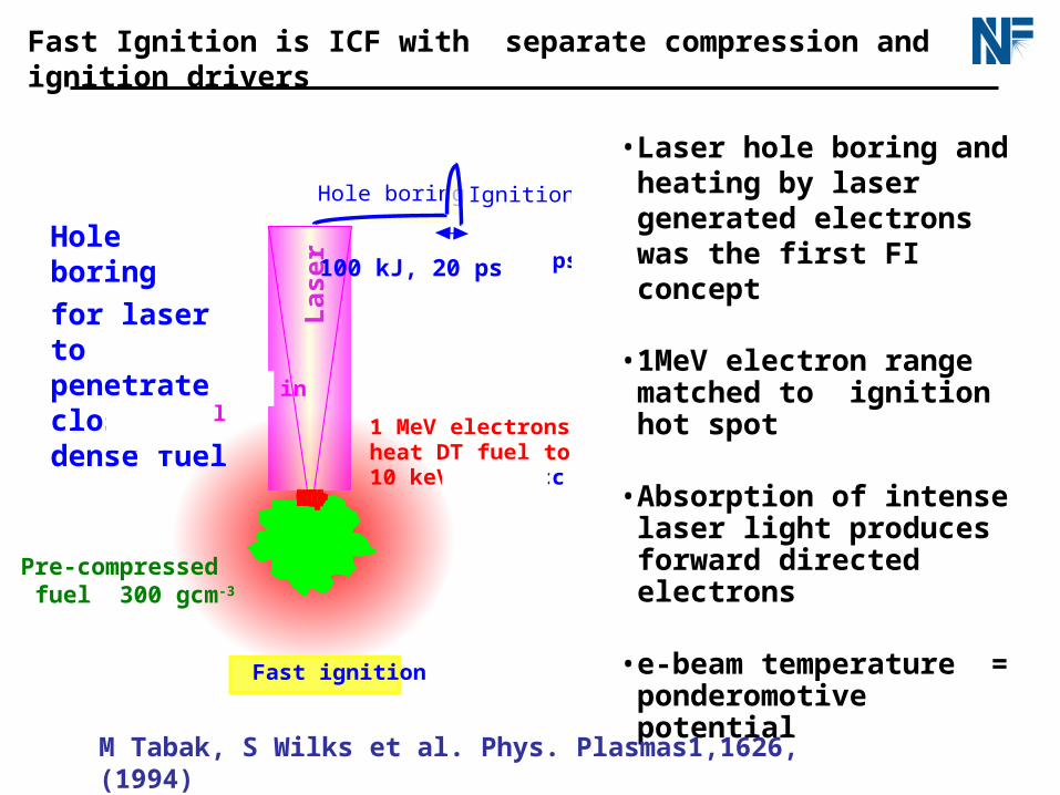
Fast Ignition is ICF with separate compression and ignition drivers
10 kJ, 10 ps
Hole boring Ignition
1 MeV electrons heat DT fuel to10 keV 300 g/cc
Fast ignition
Light pressure bores hole in coronal plasma
• Laser hole boring and heating by laser generated electrons was the first FI concept
• 1MeV electron range matched to ignition hot spot
• Absorption of intense laser light produces forward directed electrons
• e-beam temperature = ponderomotive potential
100 kJ, 20 ps Hole boring
for laser to penetrate close to dense fuel
Pre-compressed fuel 300 gcm-3
M Tabak, S Wilks et al. Phys. Plasmas1,1626, (1994)
Las
er
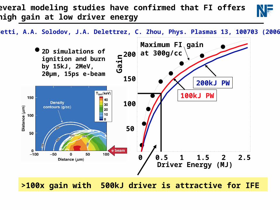
2D simulations ofignition and burnby 15kJ, 2MeV,20µm, 15ps e-beam
0 0.5 1 1.5 2 2.5
50
100
150
200Maximum FI gain at 300g/cc
100kJ PW
200kJ PW
Several modeling studies have confirmed that FI offers high gain at low driver energy
e.g. R. Betti, A.A. Solodov, J.A. Delettrez, C. Zhou, Phys. Plasmas 13, 100703 (2006)
Driver Energy (MJ)
Ga
in
>100x gain with 500kJ driver is attractive for IFE
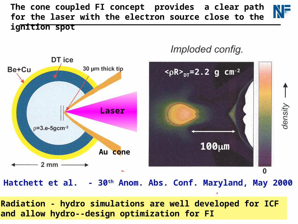
Laser
Au cone
The cone coupled FI concept provides a clear path for the laser with the electron source close to the ignition spot
100m
<R>DT=2.2 g cm-2
Radiation - hydro simulations are well developed for ICF and allow hydro--design optimization for FI
S Hatchett et al. - 30th Anom. Abs. Conf. Maryland, May 2000
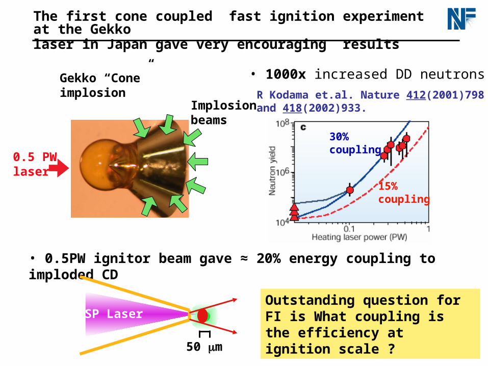
15%coupling
30%coupling
R Kodama et.al. Nature 412(2001)798 and 418(2002)933.Implosion
beams
0.5 PW laser
Gekko “Cone” implosion
The first cone coupled fast ignition experiment at the Gekko laser in Japan gave very encouraging results
• 0.5PW ignitor beam gave ≈ 20% energy coupling to imploded CD
• 1000x increased DD neutrons
Outstanding question for FI is What coupling is the efficiency at ignition scale ?
50 m
SP Laser
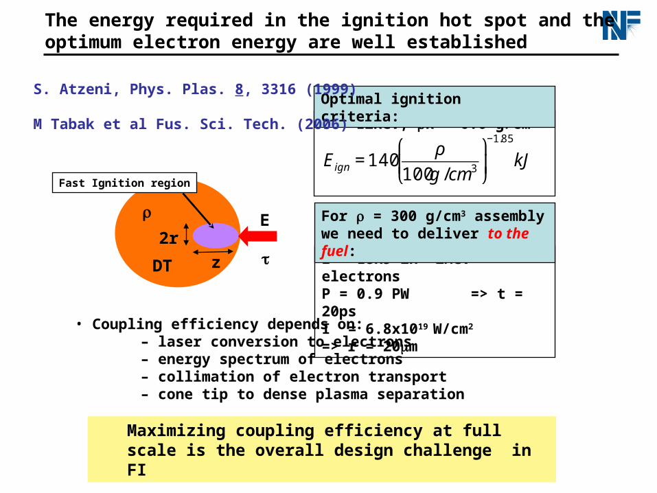
The energy required in the ignition hot spot and the optimum electron energy are well established
E
z
2r
DT
Fast Ignition region
T = 12keV, R = 0.6 g/cm2
Optimal ignition criteria:
E = 18kJ in <2MeV> electronsP = 0.9 PW => t = 20psI = 6.8x10¹⁹ W/cm2 => r = 20m
For = 300 g/cm3 assemblywe need to deliver to the fuel:
S. Atzeni, Phys. Plas. 8, 3316 (1999)
M Tabak et al Fus. Sci. Tech. (2006)
• Coupling efficiency depends on:– laser conversion to electrons– energy spectrum of electrons– collimation of electron transport – cone tip to dense plasma separation
€
Eign = 140ρ
100g /cm3
⎛
⎝ ⎜
⎞
⎠ ⎟
−1.85
kJ
Maximizing coupling efficiency at full scale is the overall design challenge in FI
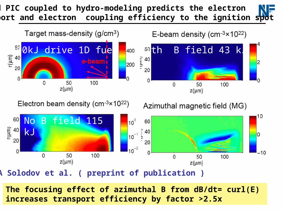
Hybrid PIC coupled to hydro-modeling predicts the electron transport and electron coupling efficiency to the ignition spot
No B field 115 kJ
With B field 43 kJ300kJ drive 1D fuel
The focusing effect of azimuthal B from dB/dt= curl(E) increases transport efficiency by factor >2.5x
A A Solodov et al. ( preprint of publication )
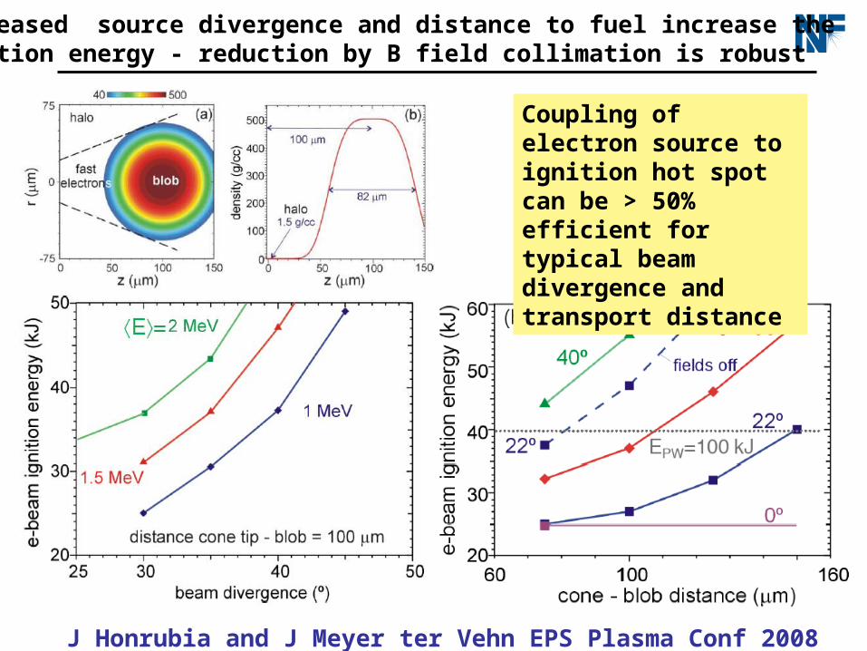
Increased source divergence and distance to fuel increase the ignition energy - reduction by B field collimation is robust
Coupling of electron source to ignition hot spot can be > 50% efficient for typical beam divergence and transport distance
J Honrubia and J Meyer ter Vehn EPS Plasma Conf 2008
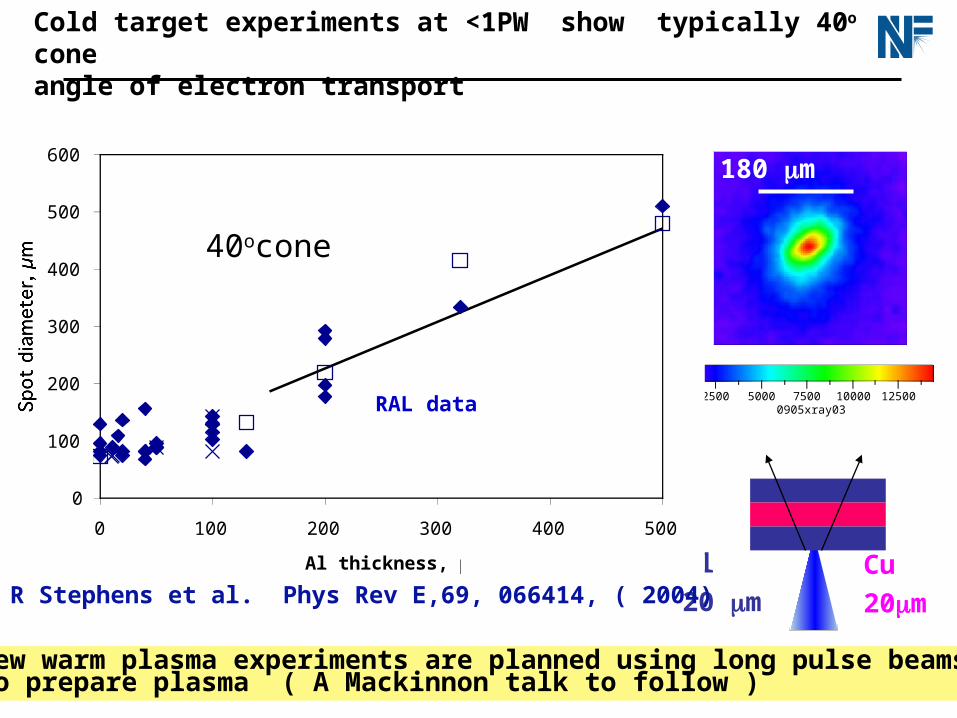
Cold target experiments at <1PW show typically 40o cone angle of electron transport
Al thickness micron
LULI
20J,0.5 ps
RAL
100J,0.8 ps
Cone angle 40o
Min radius 37 m
2500 5000 7500 10000 125000905xray03
180 m
Cu
20m
Al
20 m
0
100
200
300
400
500
600
0 100 200 300 400 500
Al thickness, µm
Spot diameter, µm RAL data
New warm plasma experiments are planned using long pulse beamsto prepare plasma ( A Mackinnon talk to follow )
40ocone
R Stephens et al. Phys Rev E,69, 066414, ( 2004)
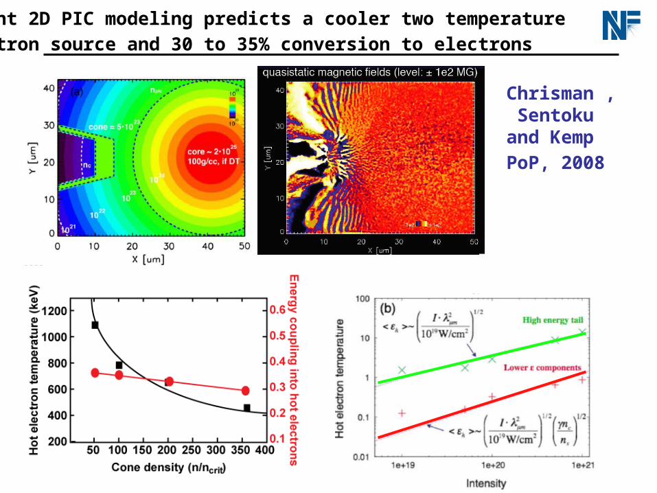
Recent 2D PIC modeling predicts a cooler two temperature
electron source and 30 to 35% conversion to electrons
Chrisman , Sentoku and Kemp
PoP, 2008
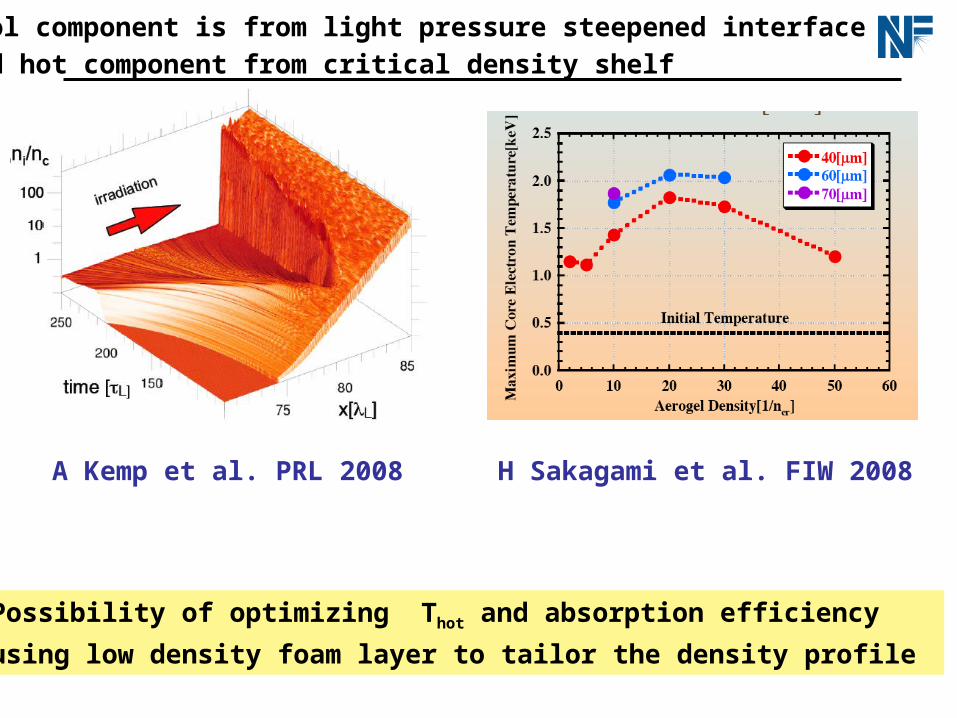
Cool component is from light pressure steepened interface
and hot component from critical density shelf
Possibility of optimizing Thot and absorption efficiency
using low density foam layer to tailor the density profile
H Sakagami et al. FIW 2008A Kemp et al. PRL 2008
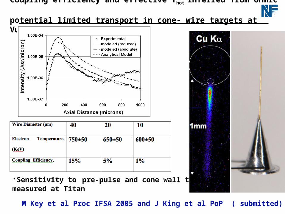
Coupling efficiency and effective Thot inferred from Ohmic potential limited transport in cone- wire targets at Vulcan PW
500 µm
1m 10 m
256 XUV
M Key et al Proc IFSA 2005 and J King et al PoP ( submitted)
•Sensitivity to pre-pulse and cone wall thicknessmeasured at Titan
QuickTime™ and aTIFF (LZW) decompressor
are needed to see this picture.
Electron source studies with the Titan laser also point to eletron temperature < ponderomotive potential
•Hybrid PIC modeling of K data gives conversion efficiency •Thot analysis using focal spot power fraction v intensity
• Bremsstrahlung data consistent with CSK PIC modeling
More in talk by R Stephens to follow

Point designs require simultaneous optimizing of many aspects of the hot electron generation, electron transport and hydrodynamics
Compressed fuel
Near 1-D isochoric implosions to minimize low density high
temperature hotspot at center
ConeMinimize transport distance from cone to fuel
Minimize high-Z cone material in fuel
Cone tip survival
clear path for laser
The cone tip hydro problem is very challenging at full scale because at fixed separation of tip and ignition spot the pressure is much higher relative to smaller scale e.g. Gekko experiment

40 m
90 m
298 m
25 kJ Omega Scale
1D target designs for direct-drive FI use massive wetted foam shells insensitive to fluid instability
R3g/cm2 R1.9g/cm2 R0.7g/cm2
<>300-500g/cm3
R. Betti and C. Zhou, Phys. Plasmas 12, 110702 (2005)
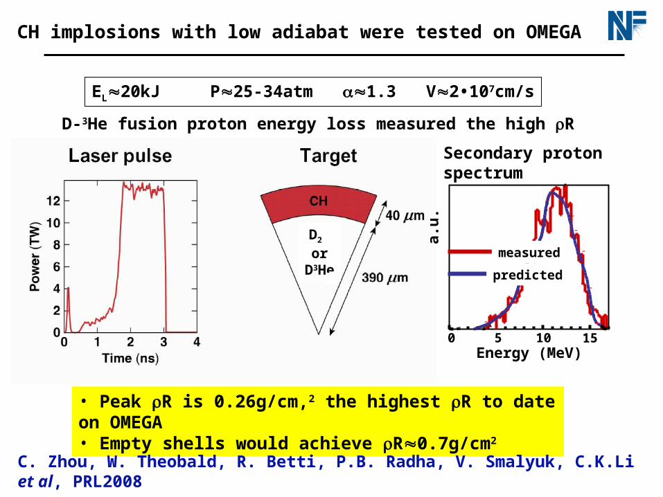
EL20kJ P25-34atm 1.3 V2•107cm/s
• Peak R is 0.26g/cm,2 the highest R to date on OMEGA• Empty shells would achieve R0.7g/cm2
C. Zhou, W. Theobald, R. Betti, P.B. Radha, V. Smalyuk, C.K.Li et al, PRL2008
CH implosions with low adiabat were tested on OMEGA
D2 or
D3He
0 5 10 15
measured
predicted
Secondary proton spectrum
Energy (MeV)
a.u
.
D-3He fusion proton energy loss measured the high R

NIF can drive full scale FI targets using 650kJ indirect drive and ID designs for CD and DT are being developed
Small hotspot r ~ 2 g/cm2
1235 µm
1070 µm
870 µm
1139 µm1087 µm
DT
Be
10-6g/cm3
DT
Be
den
sity
(g
/cm
3)
radiustime (ns)
Tra
d (
eV)
Be (0.9%) Cu
•Peak power: 70TW
•Pulse length: 32 ns
•Max blue energy: 650kJ
•Contrast ratio: 35:1
•Peak Trad = 210eV
Hydro tests with Be/CD targets on NIF
will begin in 2010
More in talk by D Clark to follow
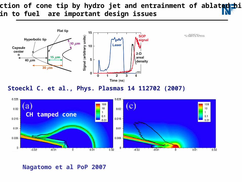
Destruction of cone tip by hydro jet and entrainment of ablated high z cone in to fuel are important design issues
QuickTime™ and aTIFF (Uncompressed) decompressor
are needed to see this picture.
Stoeckl C. et al., Phys. Plasmas 14 112702 (2007)
Nagatomo et al PoP 2007
CH tamped cone
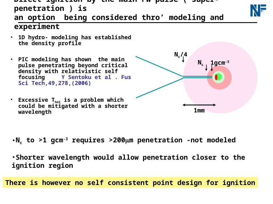
Direct ignition by the main PW pulse ( super-penetration ) isan option being considered thro’ modeling and experiment
• 1D hydro- modeling has established the density profile
• PIC modeling has shown the main pulse penetrating beyond critical density with relativistic self focusing Y Sentoku et al . Fus Sci Tech,49,278,(2006)
• Excessive Thot is a problem which could be mitigated with a shorter wavelength
•Nc to >1 gcm-3 requires >200m penetration -not modeled
•Shorter wavelength would allow penetration closer to the ignition region
1mm
Nc/4Nc 1gcm-3
There is however no self consistent point design for ignition
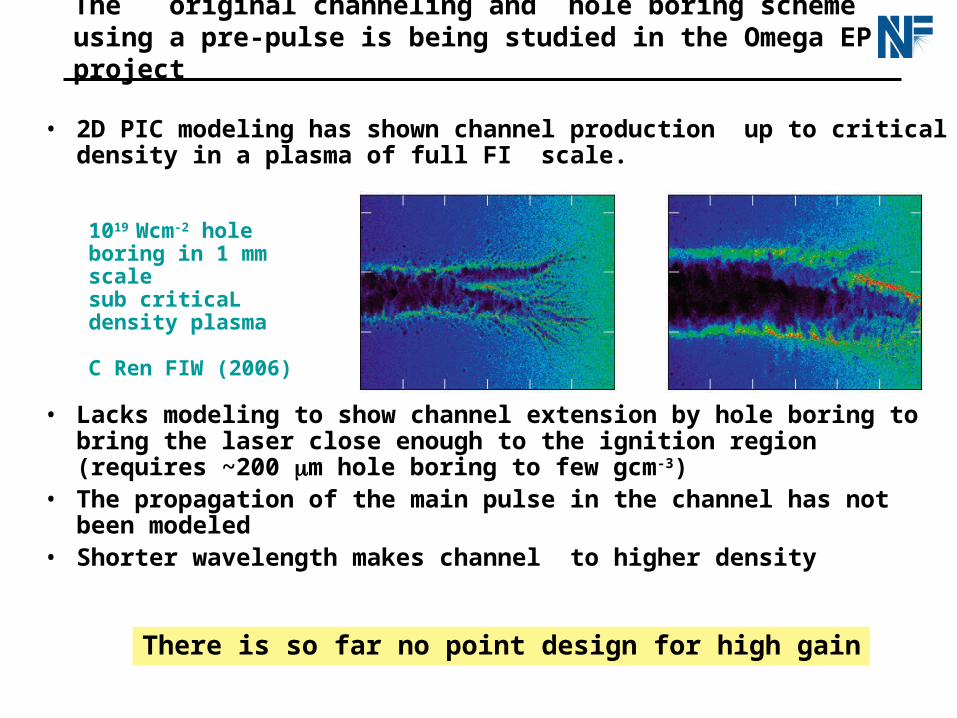
• 2D PIC modeling has shown channel production up to critical density in a plasma of full FI scale.
• Lacks modeling to show channel extension by hole boring to bring the laser close enough to the ignition region (requires ~200 m hole boring to few gcm-3)
• The propagation of the main pulse in the channel has not been modeled
• Shorter wavelength makes channel to higher density
The original channeling and hole boring scheme using a pre-pulse is being studied in the Omega EP project
1019 Wcm-2 hole boring in 1 mm scale sub criticaL density plasma C Ren FIW (2006)
There is so far no point design for high gain

Ion fast ignition by protons or carbon ions offers alternatives
with some attractive features •Light pressure and BOA for C ions NEW
•TNSA for protons
J Honrubia EPS Plasma Conf 2008
M Key et al Fus Sci Tech 2006
J Fernandez et al. Proc IFSA 2007 and talk to follow
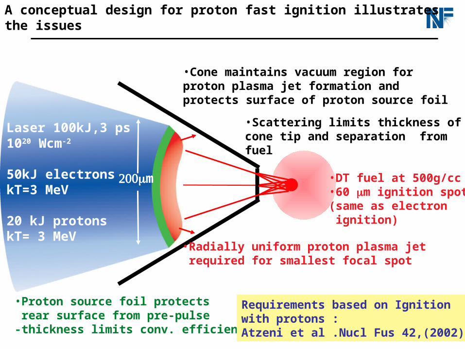
A conceptual design for proton fast ignition illustrates the issues
XUV
PW laser
Laser
Proton heating
Cu K image
m
Laser 100kJ,3 ps1020 Wcm-2
50kJ electrons kT=3 MeV
20 kJ protons kT= 3 MeV
•Radially uniform proton plasma jet required for smallest focal spot
•Proton source foil protects rear surface from pre-pulse -thickness limits conv. efficiency
•Cone maintains vacuum region for proton plasma jet formation and protects surface of proton source foil
•DT fuel at 500g/cc•60 m ignition spot(same as electron ignition)
•Scattering limits thickness of cone tip and separation from fuel
Requirements based on Ignitionwith protons :Atzeni et al .Nucl Fus 42,(2002)
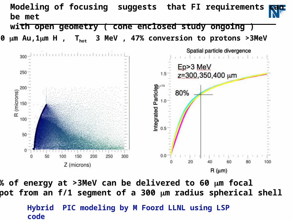
Modeling of focusing suggests that FI requirements can be met with open geometry ( cone enclosed study ongoing )
Hybrid PIC modeling by M Foord LLNL using LSP code
80% of energy at >3MeV can be delivered to 60 m focal spot from an f/1 segment of a 300 m radius spherical shell
10 m Au,1m H , Thot 3 MeV , 47% conversion to protons >3MeV
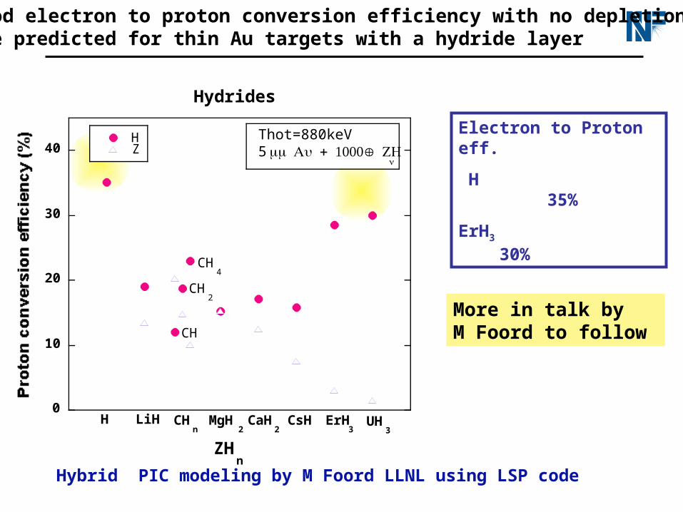
Good electron to proton conversion efficiency with no depletion are predicted for thin Au targets with a hydride layer
Electron to Proton eff.
H 35%
ErH3 30%
Hybrid PIC modeling by M Foord LLNL using LSP code
0
10
20
30
40
Hydrides
BC
H LiH CHn
MgH2
CaH2
CsH ErH3
UH3
CH4
CH2
CH
HZ
ZHn
Thot=880keV5 + 1 m Au Å ZH
n
More in talk by M Foord to follow
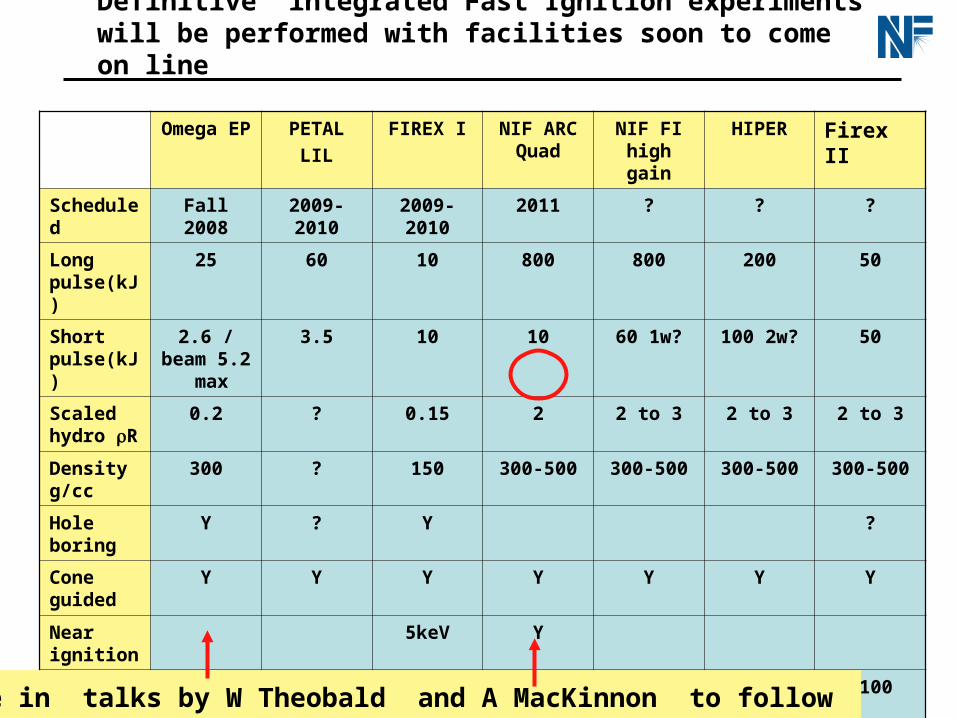
Definitive integrated Fast Ignition experiments will be performed with facilities soon to come on line
Omega EP
PETAL
LIL
FIREX I NIF ARC Quad
NIF FI high gain
HIPER Firex II
Scheduled
Fall 2008 2009-2010 2009-2010 2011 ? ? ?
Long pulse(kJ)
25 60 10 800 800 200 50
Short pulse(kJ)
2.6 / beam 5.2 max
3.5 10 10 60 1w? 100 2w? 50
Scaled hydro R
0.2 ? 0.15 2 2 to 3 2 to 3 2 to 3
Density g/cc
300 ? 150 300-500 300-500 300-500 300-500
Hole boring
Y ? Y ?
Cone guided
Y Y Y Y Y Y Y
Near ignition
5keV Y
High gain >100 >100 >100
More in talks by W Theobald and A MacKinnon to follow
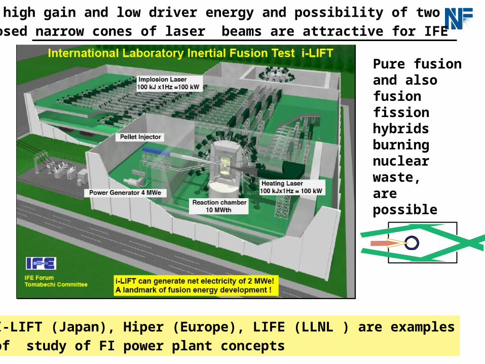
The high gain and low driver energy and possibility of two
opposed narrow cones of laser beams are attractive for IFE
Pure fusion and also fusion fission hybrids burning nuclear waste, are possible
I-LIFT (Japan), Hiper (Europe), LIFE (LLNL ) are examples
of study of FI power plant concepts
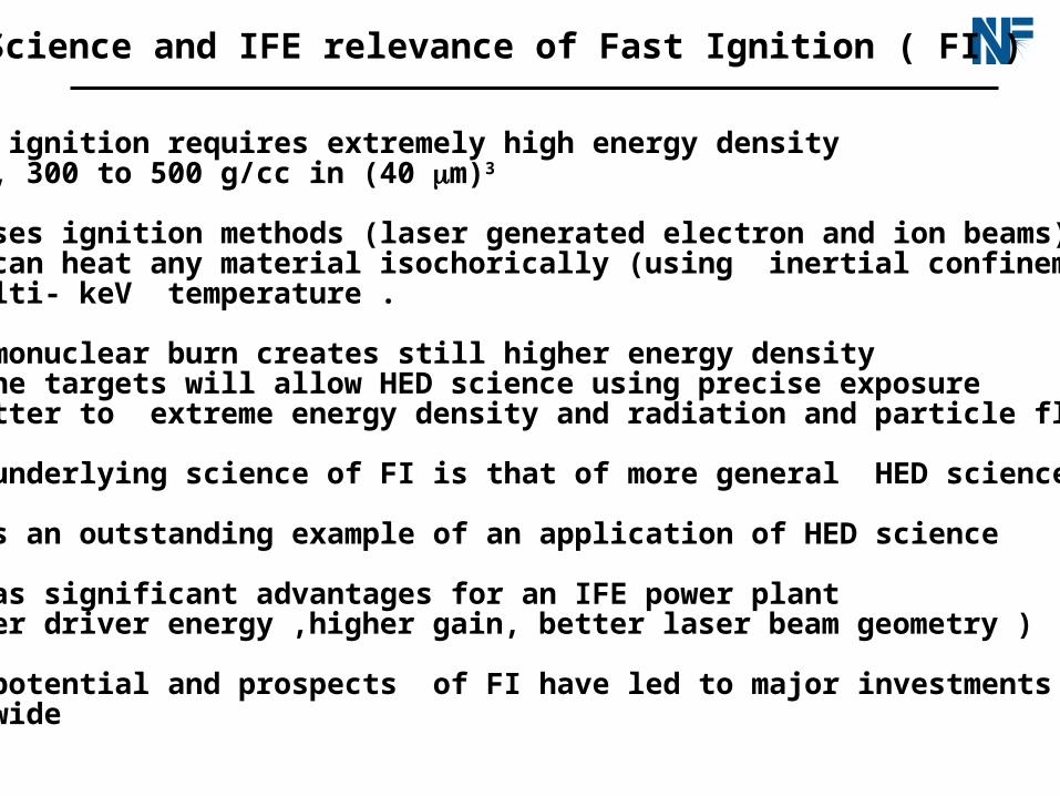
HED Science and IFE relevance of Fast Ignition ( FI )
•Fast ignition requires extremely high energy density 10keV, 300 to 500 g/cc in (40 m)3
•FI uses ignition methods (laser generated electron and ion beams)that can heat any material isochorically (using inertial confinement) to multi- keV temperature .
•Thermonuclear burn creates still higher energy densityFI cone targets will allow HED science using precise exposure of matter to extreme energy density and radiation and particle fluxes
•The underlying science of FI is that of more general HED science
•FI is an outstanding example of an application of HED science
•FI has significant advantages for an IFE power plant ( lower driver energy ,higher gain, better laser beam geometry )
•The potential and prospects of FI have led to major investments worldwide
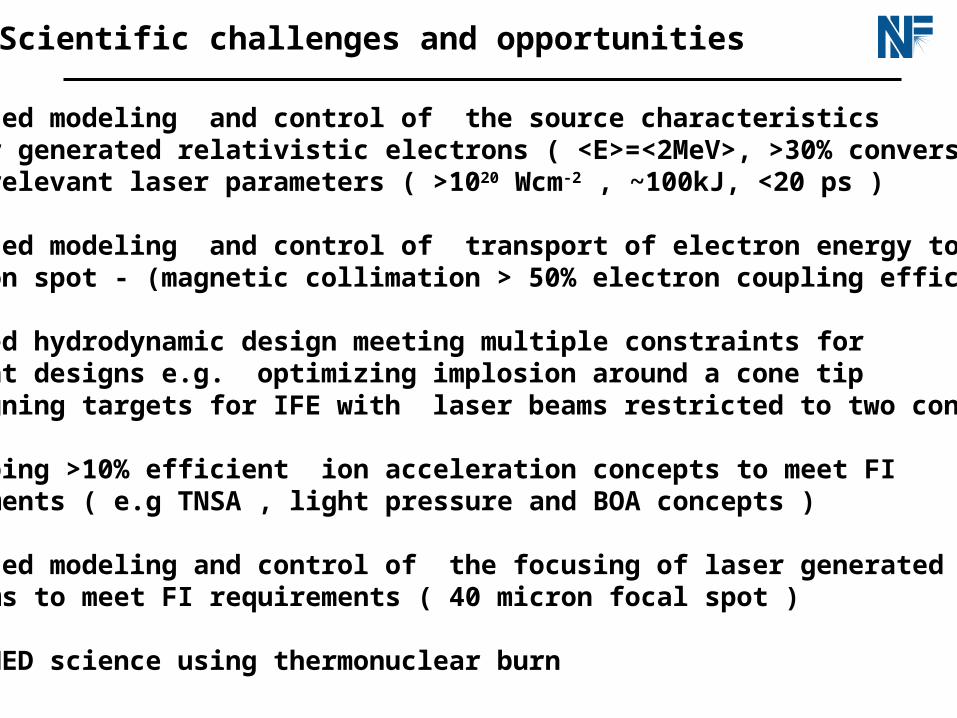
Scientific challenges and opportunities
•Validated modeling and control of the source characteristics of laser generated relativistic electrons ( <E>=<2MeV>, >30% conversion ) at FI relevant laser parameters ( >1020 Wcm-2 , ~100kJ, <20 ps )
•Validated modeling and control of transport of electron energy to ignition spot - (magnetic collimation > 50% electron coupling efficiency )
•Advanced hydrodynamic design meeting multiple constraints for FI point designs e.g. optimizing implosion around a cone tip - designing targets for IFE with laser beams restricted to two cones
•Developing >10% efficient ion acceleration concepts to meet FI requirements ( e.g TNSA , light pressure and BOA concepts ) •Validated modeling and control of the focusing of laser generated ion beams to meet FI requirements ( 40 micron focal spot )
•Novel HED science using thermonuclear burn
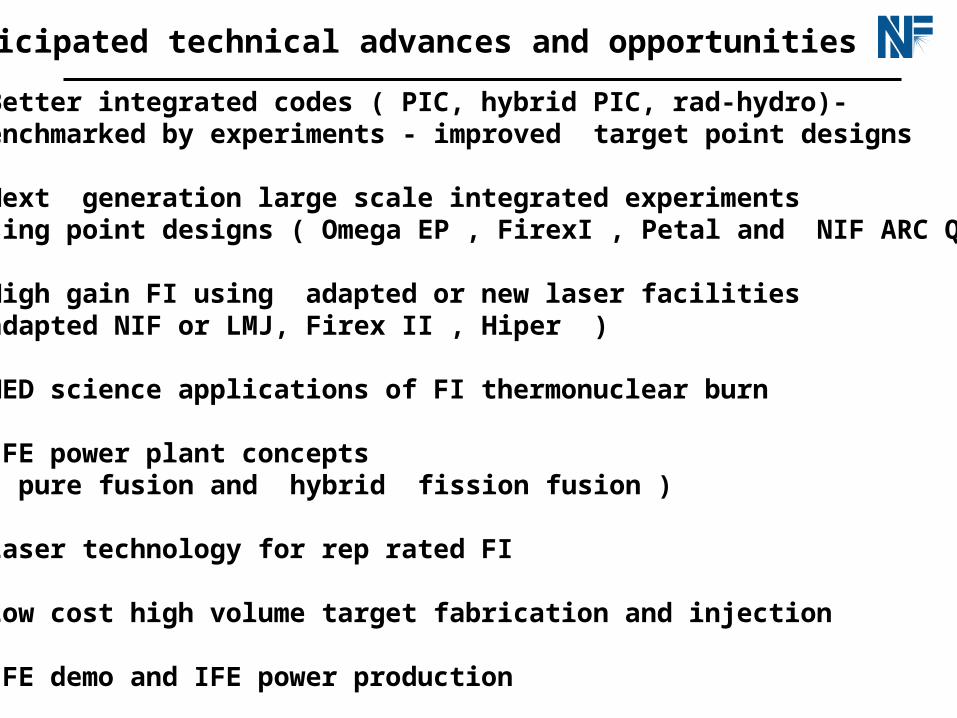
Anticipated technical advances and opportunities
•Better integrated codes ( PIC, hybrid PIC, rad-hydro)- benchmarked by experiments - improved target point designs
•Next generation large scale integrated experiments using point designs ( Omega EP , FirexI , Petal and NIF ARC Quad )
•High gain FI using adapted or new laser facilities (adapted NIF or LMJ, Firex II , Hiper )
•HED science applications of FI thermonuclear burn
•IFE power plant concepts ( pure fusion and hybrid fission fusion )
•Laser technology for rep rated FI
•Low cost high volume target fabrication and injection •IFE demo and IFE power production