revision 1 2011 virginia work area protection manual · 2011 virginia work area protection manual...
TRANSCRIPT

Effective April 1, 2015 for State Forces & Effective starting on the July 2015 Advertisement
REVISION 12011 VIRGINIA WORK AREA
PROTECTION MANUAL
2
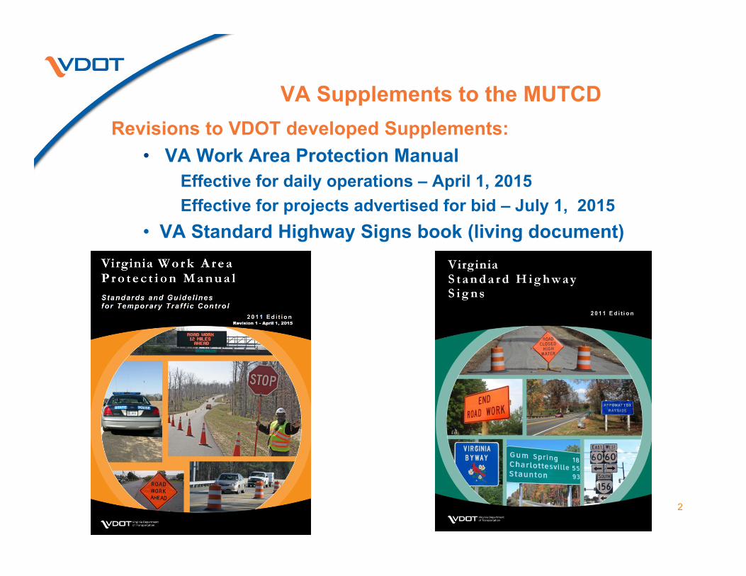
VA Supplements to the MUTCD Revisions to VDOT developed Supplements:
• VA Work Area Protection Manual Effective for daily operations – April 1, 2015Effective for projects advertised for bid – July 1, 2015
• VA Standard Highway Signs book (living document)

3
2011 VA WAPM Revision Documentation“Technical Changes in Revision 1 of the
2011 Virginia Work Area Protection Manual”
• Lists all revisions in the manual by:– Chapter– Section– Paragraph/Figure/
Table– Sign Designation
• Provides specific information:– What was revised– Why it was
revised, as applicable

4
Changes/Revisions Identified by:
• New date at the top of the page (April 2015)
• Content; – Gray Shading– Superscript 1 following the revision– Revised TTC Figures designated by superscript 1
• Footnote at the bottom of the page noting the revision number and date
2011 VA WAPM Revision Documentation

Chapter 6AGeneral
5
Revision 1 2011 Work Area Protection Manual

6
Revision 1 2011 Work Area Protection Manual
Section 6A.03 Definitions of Words and Phrases in This Manual24. Limited Access Highway revised33. Portable Temporary Rumble Strip (PTRS)
• Alerts driver• Transverse rumble strip• Extends across the travel lane• Installed & removed quickly
Section 6A.04Meanings of Acronyms and Abbreviations…26. PTRS Portable Temporary Rumble Strip

Chapter 6BFundamental Principles
7
Revision 1 2011 Work Area Protection Manual
A number in paraphrases represents the revised Section’s paragraph.

8
Revision 1 2011 Work Area Protection Manual
Section 6B.01Fundamental Principles of TTC
(15) When flagging operation is suspended:
The flagger symbol sign shall be removed or covered.

Chapter 6CTemporary Traffic Control
Elements
9
Revision 1 2011 Work Area Protection Manual
A number in paraphrases represents the revised Section’s paragraph.

Added:• 2 mile is the Max.
length of a work space unless approved by the RTE
• Paved shoulder taper reference 6C.09(11).
Revision 1 2011 Work Area Protection Manual
Figure 6C-1, Component Parts of TTC Zone
10

Table 6C-1 & Table 6H-5, Recommended Spacing of Advance Warning Signs
Road Type Spacing (Feet)
Urban street with 25 mph or less posted speed 100 – 200
Urban street with 30 to 40 mph posted speed 250 – 350
* All Other Roadways with 45 mph or less posted speed 350 – 500
All Other Roadways with greater than 45 mph posted speed 500 – 800
Limited Access highways 1300 – 1500
11
Revision 1 2011 Work Area Protection Manual
Changed title to “Recommended Spacing of Advance Warning Signs”

Posted Speed Limit (mph) Distance (Feet)< 20 115 – 120 25 155 – 1651
30 200 – 210 35 250 – 260 40 305 – 3251
45 360 – 380 50 425 – 445 55 500 – 5301
60 570 – 6001
65 645 – 675 70 730 – 760 75 820 – 850
Revision 1 2011 Work Area Protection Manual
Changed distances:25 mph 155 – 1651
40 mph 305 – 3251
55 mph 500 – 5301
60 mph 570 – 6001
Buffer Space lengthschanged in
TIMC-1 to TIMC-4
Table 6C-2, Length of the Longitudinal Buffer SpaceTable 6E-1, Longitudinal Buffer Space1 (title change)Table 6H-3, Longitudinal Buffer Space1 (title change
12
Section 6C.06 Buffer Space (05) These distances should be increased for downgrades andother geometric conditions that affect stopping distance.1

13
Revision 1 2011 Work Area Protection Manual
Section 6C.08 Termination Area(02) The END ROAD WORK sign
should be used to inform road users they can resume normal operations.
(04) END WORK ZONE SPEED LIMIT sign is used on un-posted secondary roads, otherwise the SPEED LIMIT sign is used. When part of a project speed is reduced, the original speed limit shall be posted 500'+ past the work area.

14
Table 6C-4, Taper ChartTable 6H-2, Taper Chart
Changed 40 MPHlength
270 – 295
Revision 1 2011 Work Area Protection Manual

15
Revision 1 2011 Work Area Protection Manual
Chapter 6C
Section 6C.09 Tapers:(11) Paved shoulder having a width of 8 feet
or more, a shoulder taper shall be used in advance of the merging taper
Channelizing devices match those used in the merging taper

16
Revision 1 2011 Work Area Protection Manual
Figure 6C-2, Example of Types of Tapers
Changed:• Work space to
Activity Area• Channelizing device
spacing to match roadway spacing

17
Revision 1 2011 Work Area Protection Manual
Changed:• Work space to
Activity Area
Figure 6C-3, Example of a One-Lane,Two-Way Taper

Chapter 6DPedestrian and Worker
Safety
18
Revision 1 2011 Work Area Protection Manual
A number in paraphrases represents the revised Section’s paragraph.

19
Revision 1 2011 Work Area Protection Manual
Section 6D.03 Worker Safety Consideration(05) & (06) Defines Class E trousers:
Full length waistband trousers or overalls that meet minimum requirements of Performance Class 3 risk requirements of ANSI/ISEA 107-2010
Shorts shall note be worn at any time.(07) ANSI/ISEA 107/2010 headwear may be worn

20
Revision 1 2011 Work Area Protection Manual
Section 6D.03 Worker Safety Consideration
(09) Uniform law enforcement personnel high-visibility safety apparel shall meet Performance Class 2 or 3 requirements of ANSI/ISEA 107/2010 when exposed to traffic
(11) High-visibility safety apparel shall: • be securely fastened• be visible for 360°around the wearer• provide conspicuity of fluorescent
colors, retroreflectivity and pattern

Chapter 6EFlagger Control
21
Revision 1 2011 Work Area Protection Manual
A number in paraphrases represents the revised Section’s paragraph.

22
Revision 1 2011 Work Area Protection Manual
Section 6E.01 Qualifications for a Flagger
(03) Recertification for Flaggers• 2 years VDOT Flagger Certification • 4 years Flagger Certification with:
• VDOT Basic Work Zone Traffic Control Training • VDOT Intermediate Work Zone Traffic Control
Training• ATSSA’s classroom Flagger Certification
Program

23
Revision 1 2011 Work Area Protection Manual
Section 6E.02 High Visibility Apparel(04) Flaggers:
• Required to wear ANSI 107/ISEA 107-2010 Performance Class 3
• Nighttime flaggers apparel includes full length Type E trousers or overalls
• Shorts shall not be worn
(05) Defines Class E trousers as full length waistband trousers or overalls that meet minimum requirements of ANSI/ISEA 107-2010

24
Revision 1 2011 Work Area Protection Manual
Section 6E.02 High Visibility Apparel(06) Apparel shall be securely fasten apparel so
retroreflectivity is visible 360 around wearer.(07) Uniformed law enforcement personnel shall
wear ANSI/ISEA 107-2010 Performance Class 2 or 3 to:
• Direct traffic, investigate crashes, handle lane closures, obstructed roadways and disasters
(09) ANSI/ISEA 107-2010 headwear may be worn.

25
Revision 1 2011 Work Area Protection Manual
Section 6E.03 Hand Signaling Devices:(10) Flag:
• 24 x 24 inches squareFlag Staff:• 1 to 1 ¾ inches in diameter staff
(12) Nighttime both side of the flag shall be retroreflectorized orange/red in color

26
Revision 1 2011 Work Area Protection Manual
Section 6E.04,Automated Flagger Assistances Devices:
(13) - Described Method 1 as Stop/Slow AFAD- Described Method 2 as Red/Yellow Lens
AFAD (14) Two AFADs shall be used to control one-
lane two-way traffic(15) When one flagger operates both AFADs, the
flagger shall have an unobstructed view of approaching traffic in both directions

Revision 1 2011 Work Area Protection Manual
Figure 6E-1, Example of the Use of Stop/Slow AFADFigure 6E-2, Example of the Use of Red/Yellow Lens AFAD
Figure 6E-1 Figure 6E-227
AFADs control
one-lane two-way
trafficon both
ends

28
• Changed channelizing devices spacing to match typical spacing of channelizing devices
• Certified flagger(s) trained to operate AFAD unit
Revision 1 2011 Work Area Protection Manual
Figures 6E-1 & 6E-2 Continued

29
Revision 1 2011 Work Area Protection Manual
Figure 6E-4, Flagger Requirements (Sheet 2 of 2)
Matches Table 6E-1: Longitudinal Buffer Space

30
Revision 1 2011 Work Area Protection Manual
Section 6E.08, Flagger Station(01) When the Flagger operation is suspended:
• The Flagger (W20-1) symbol sign shall be removed or covered from road user
No longer allowed to be turned sign from traffic

Chapter 6FTemporary Traffic Control
Devices
31
Revision 1 2011 Work Area Protection Manual
A number in paraphrases represents the revised Section’s paragraph.

32
Revision 1 2011 Work Area Protection Manual
(22) Post-mounted rigid sign material changed to allow aluminum 0.080 inch thickness
Section 6F.02, General Characteristics of Signs

Table 6F-1, Temporary Traffic Control Zone Sign and Plaque Sizes
New Regulatory Signs:• Proceed When Way Is Clear (R1-V1)• Work Zone $500 Max. Fine For Exceeding Speed
Limit When Flashing (R2-V1)• Begin Right Turn Lane w/ Arrow (R3-20L, R3-20R)• Turning Vehicles Yield to Pedestrians (R10-15)
33
Revision 1 2011 Work Area Protection Manual

Table 6F-1, TTC Zone Sign and Plaque Sizes
New Warning Signs:• Crash Area Keep Clear (WO-V1)• Grooved Pavement Ahead (W20-V14)• Median Crossover Closed Ahead (W20-V15)• Median Crossover Closed (W20-V16)• Rumble Strips Ahead (W20-V26)• Emergency Work Ahead (W20-V27)• Road Patching Ahead (W21-V18)• Road Patching Next X Miles (W21-V19)
34
Revision 1 2011 Work Area Protection Manual
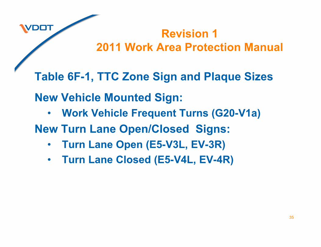
Table 6F-1, TTC Zone Sign and Plaque Sizes
New Vehicle Mounted Sign:• Work Vehicle Frequent Turns (G20-V1a)
New Turn Lane Open/Closed Signs:• Turn Lane Open (E5-V3L, EV-3R)• Turn Lane Closed (E5-V4L, EV-4R)
35
Revision 1 2011 Work Area Protection Manual

Table 6F-1, TTC Zone Sign and Plaque Sizes
Additional Guide Signs:• Interstate Route Shields• U. S. Route Markers• VA Primary Route Markers• VA Circular Secondary Route Markers• Cardinal Directional Auxiliary• Directional Arrows Auxiliary
• Detour Route Shield Assemblies (Long-term)• WZ – Orange Arrows • Incident Management – Pink Arrows 36
Revision 1 2011 Work Area Protection Manual

37
Revision 1 2011 Work Area Protection Manual
• Post may extend 2' above sign
• (08) (10) Height to bottom of • Plaque 7' max – 6' min• Sign 8' max – 7' min
• Adjusted measurements for 6x6 breakaway holes asrelated to ground line
• Verify post installation in STANDARDS/Plans Fig. 6F-1Height and Lateral Location of Signs
– Typical Post-Mounted Installations
Section 6F.03, Sign Placement & Figure 6F-1
38
Revision 1 2011 Work Area Protection Manual
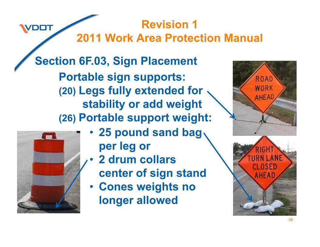
Portable sign supports:(20) Legs fully extended for
stability or add weight(26) Portable support weight:
Section 6F.03, Sign Placement
• 25 pound sand bag per leg or
• 2 drum collars center of sign stand
• Cones weights no longer allowed
39
Revision 1 2011 Work Area Protection Manual
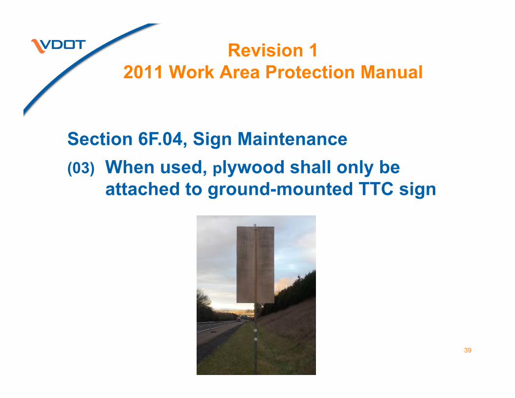
Section 6F.04, Sign Maintenance(03) When used, plywood shall only be
attached to ground-mounted TTC sign

40
Revision 1 2011 Work Area Protection Manual
(01) Code of VA amended(02) New sign shown has been
required since July 1, 2012
(03) (06)Ty B flashing light shall be activated remotely when workers are present
Section 6F.13 & Figure 6F-2Work Zone $500 Max. Fine For Exceeding Speed Limit When Flashing Sign (R2-V1)

41
Revision 1 2011 Work Area Protection Manual
(04) An engineering study should determine the use of the PROCEED WHEN WAY IS CLEAR sign when a stop or yield condition is used to control traffic on a two-lane roadway (TTC-25).
Section 6F.17 Special Regulatory Signs

42
Revision 1 2011 Work Area Protection Manual
Section 6F.17,Special Regulatory Signs(09) Turning Vehicles Yield To
Pedestrian sign reminds turning motorists to yield to pedestrians
Section 6F.18, Warning Signs Function, Design, Application(14) Advance warning signs shall be installed
on entrance ramps if they are not visible to ramp users

43
Revision 1 2011 Work Area Protection Manual
(16) Used when unexpected or natural event must be dealt with urgently; not part of daily operation or planned work
(13) Should be first sign in Temporary Incident Management Control Zone
(14) May be used in lieu of ROAD WORK AHEAD
(15) Supporting warning signs may be florescent orange with black legend & border
Section 6F.21, …. Emergency Work Ahead

44
Revision 1 2011 Work Area Protection Manual
• Shall be used in advance of the point where the median crossover is closed
• A NO LEFT TURN (R3-2) sign shall be used in conjunction with the MEDIAN CROSSOVER signs
• Median Crossover Closed installed at the beginning of the turn lane taper or 200' to 300' in advance of the of a crossover without turn lane.
Section 6F.26 (05) …. Median Crossover Closed Ahead & Median Crossover Closed
MEDIANCROSSOVER
CLOSED
MEDIANCROSSOVER
CLOSEDAHEAD

45
Revision 1 2011 Work Area Protection Manual
Section 6F.26 Section 6F.28
Required as of July 1, 2014
46
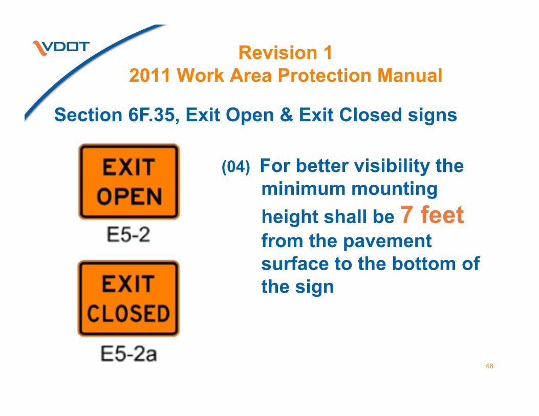
Revision 1 2011 Work Area Protection Manual
(04) For better visibility the minimum mounting height shall be 7 feet from the pavement surface to the bottom of the sign
Section 6F.35, Exit Open & Exit Closed signs

47
Revision 1 2011 Work Area Protection Manual
Section 6F.38, Flagger Sign, XX Feet Plaque
(02) When flagging operation is suspended the Flagger symbol sign shall be removed or covered

48
Revision 1 2011 Work Area Protection Manual
(05) The Truck Entering Highway sign shall be used for Logging operations .
LOG TRUCKS ENTERING HIGHWAY sign shall not be use.
Section 6F.40,… Trucks Entering Highway sign

49
Revision 1 2011 Work Area Protection Manual
Section 6F.41 (02) GROOVED PAVEMENT (W20-V14) sign may
be alternative to the ROUGH ROAD sign.(03) A MOTORCYCLE (W8-15P) plaque may
supplement a post mounted ROUGH ROAD or GROOVED PAVEMENT sign.
GROOVEDPAVEMENT

50
Revision 1 2011 Work Area Protection Manual
Section 6F.44 Section 6F.50
Required as of July 1, 2014
Section 6F.53
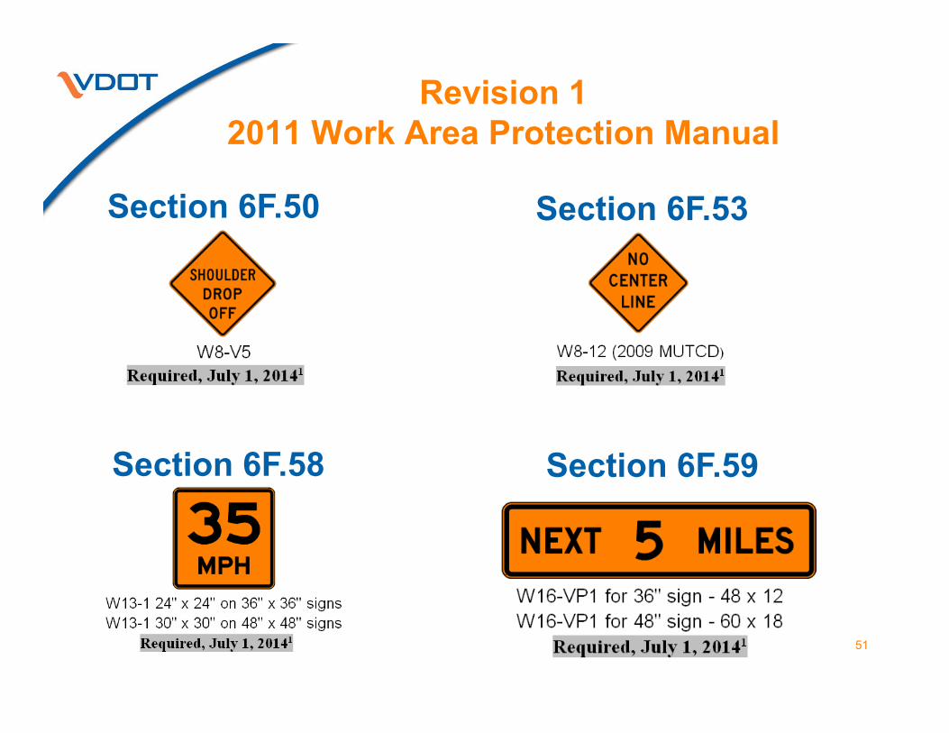
51
Revision 1 2011 Work Area Protection Manual
Section 6F.53Section 6F.50
Section 6F.58 Section 6F.59

52
Revision 1 2011 Work Area Protection Manual
Section 6F.58 Section 6F.59
Required as of July 1, 2014

53
Revision 1 2011 Work Area Protection Manual
(01) Mounted on rear of a vehicle hauling/delivering material
(02) May be displayed at all times or covered or removed when not in use
(05) Not required when the tailgate has been removed or lowered for work operations
(05) Not required on vehicles which can enter or exit the work zone at higher speeds
(03) Work Vehicle Do Not Enter is not required on 1-way, 2-lane operation
OR
(04) Required as of July 1, 2017
Optional UntilJune 30, 2017
Section 6F.64 Work Vehicle Frequent Turns sign

54
Revision 1 2011 Work Area Protection Manual
Figure 6F.5… Detour Signs for TTC
Orange directional arrow auxiliary will be required on long-term detours to improve visibility and help identify work zone detour.

55
Revision 1 2011 Work Area Protection Manual
Section 6F.68, Portable Changeable Message Boards(33) PCMS other non-crashworthy trailer
mounted devices• Intelligent Transportation Systems (ITS) • Highway Advisory Radio• Speed Trailers• CB Wizards• ITS cameras• Portable Traffic Control Signals• AFAD units• Light towers, etc.
Delineate with 4-drum taper at all times

56
Revision 1 2011 Work Area Protection Manual
Section 6F.69, Arrow Boards & Figure 6F-6• Minimum 4 channelizing device taper
delineates the arrow board at all times• Shoulder taper required if placed on paved
shoulders with a width of 8 feet or more• Delineation/channelizing devices match
those used in merging taper

57
Revision 1 2011 Work Area Protection Manual
(01) Constructed of lightweight, formable material.
(02) Retroreflective sheeting, ASTM Type III Reboundable,1 4- to 6-inch wide alternating orange and white strips
247 Specification• Required on projects advertised July 1, 2012.• Advertised prior to July 1, 2012 may be used until
July 1, 2016.• Regardless of dates all shall comply by July 1, 2016.
Section 6F.73, Tubular Marker:

58
Revision 1 2011 Work Area Protection Manual
(01) Retroreflective sheeting, ASTM Type III Reboundable, 6-inch wide alternating orange and white strips.
• Required on projects advertised July 1, 2012.• Advertised prior to July 1, 2012 may be used
until July 1, 2016.• Regardless of dates all shall comply by July
1, 2016.(02) Retroreflectivity sheeting should be grouped
together.
Section 6F.75, Drum:

59
Revision 1 2011 Work Area Protection Manual
(09) A four drum taper shall be used to delineate PCMS or other unmanned trailer mounted devices.
(10) Drums may be left on the shoulder but must not prohibit the use of the shoulder.
Section 6F.75, Drum:
Fig. 6F-6

60
Revision 1 2011 Work Area Protection Manual
Section 6F.76, Type 3 Barricades & Figure 6F-8 (04) Rail width
approximately 8 to 12 inches.
(17) Shall be used to close work access -entrances openings
(18) A person shall be assigned to ensure proper closure at the end of the work day
(21) Signs mounted on Ty. 3 barricade should not cover more than the top rail.
Type 3 Barricades:

Section 6F.83 Temporary Raised Islands(07) Added reference for flex post
delineators• See Figure 6 in Appendix A of this
manual or IIM-LD-93 for specific details on Temporary Asphalt Medians
Section 6F.86 Temporary Markings(05) Flexible temporary pavement markers
(FTPMs)1for up to ten consecutive days as directed by the Engineer
61
Revision 1 2011 Work Area Protection Manual

Section 6F.90 Floodlights(06) Added anti-glare shields to eliminate
glare
62
Revision 1 2011 Work Area Protection Manual

Section 6F.92 Vehicle Warning Lights(02) Deleted strobe lights
( 02 – 1.) … Sealed beams shall have a flash rate of 75 to 135 flashes per minute.
(06) Both day and night, vehicle warning lights should be used on work vehicles entering and exiting a work zone and visible from 360 degrees.
63
Revision 1 2011 Work Area Protection Manual
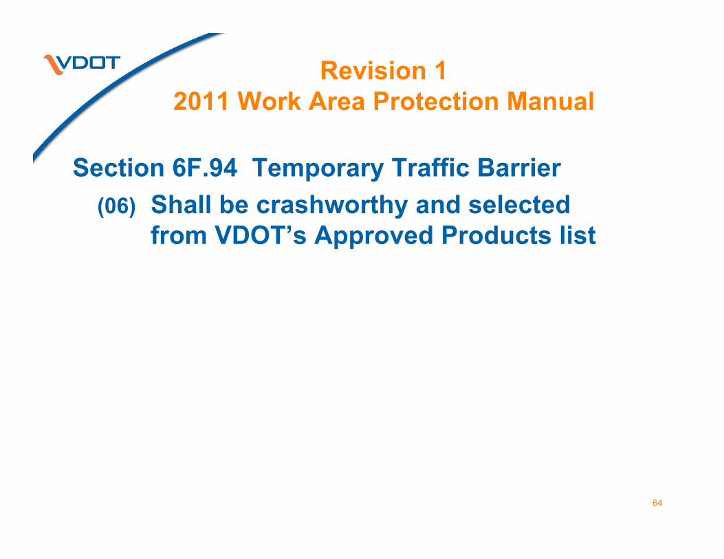
Section 6F.94 Temporary Traffic Barrier(06) Shall be crashworthy and selected
from VDOT’s Approved Products list
64
Revision 1 2011 Work Area Protection Manual

Section 6F.95 Crash Cushion(04) CRASH AREA KEEP CLEAR sign shall
be installed when a non-redirective crash cushion (impact attenuator) is directed by the plan assembly.
65
Revision 1 2011 Work Area Protection Manual

Section 6F.95 Crash CushionTruck Mounted Attenuator (TMA) shall: (06) - only be used to protect a fixed object
for incident management operation.- remain in place for no more than 24 hours after the initial scene response.
(07) have a rear panel with 6 to 8 inches wide black and fluorescent yellow (Orange still allowed) strips.
(08) be installed as tested per NCHRP350/Mash Test Level 3 criteria
66
Revision 1 2011 Work Area Protection Manual

Section 6F.95 Crash Cushion(18) Additional shadow vehicle(s) may be
used to protect workers in separate locations throughout the work area.
(20) - Channelizing devices and signs shall not be store on a shadow vehicle with a TMA.
- All other material and/or equipment on the shadow vehicle TMA shall be properly secured to prevent spillage if struck by an errant vehicle.
67
Revision 1 2011 Work Area Protection Manual

68
Revision 1 2011 Work Area Protection Manual
Portable Temporary Rumble Strips (PTRS)(03) Transverse rumble strip
Installed/removed quickly(06) Interlocking or hinged segments(07) - With stand 80,000 lbs.
- No more that 6 inches parallel incidental movement during 8 hour use
- 3 rumble strips equals an array
Section 6F.96 Rumble Strips

69
Revision 1 2011 Work Area Protection Manual
Section 6F.96 Rumble Strips & Figure TTC-23
• Approval must be granted by the Engineer
• Used in one-lane, two-way flagging operations.
• PTRS should extend across the travel lane but not encroach into the opposing lane.
• Only one array of PTRS should be used in the advance warning area.
(15)

70
Revision 1 2011 Work Area Protection Manual
Lane Closure on a Two-Lane Roadway Using Flaggers(Figure TTC-23.1)
Section 6F.96 Rumble Strips & Figure TTC-23
(16) PTRS should be installed/removed with the advance warning signs for the work operation.
(07) PTRS Spacing center to center
0 – 35 mph 5 feet36 – 55 mph 8 feet

71
Revision 1 2011 Work Area Protection Manual
Chapter 6F
Section 6G.02 Work Duration
(02 E.) Mobile is work that moves intermittently (1 to 15 minutes) or continuously.
(11) Removed reference to strobe light for vehicle mounted lights and throughout Chapter 6G.

72
Revision 1 2011 Work Area Protection Manual
Section 6G.10 Work Within the Traveled Way of a Two-Lane Highway
Support:(06) When a work zone on a two-lane highway
transitions to a multi-lane highway the temporary traffic control continues as a two-lane highway. Lane closure signs and arrow boards typically used for temporary traffic control on multi-lane highways are not needed.

73
Revision 1 2011 Work Area Protection Manual
Chapter 6F
Section 6G.24 Slow Roll Temporary Traffic Control Operation(02) Shall be approve by Regional Traffic
Engineer or their designee.(07) A control vehicle can be a contractor’s,
public agency’s or VSP’s

74
Revision 1 2011 Work Area Protection Manual
Section 6G.25 Installing/Removing Temporary Traffic Control - On a two-lane roadway:(02) Non-stationary flagging operation using:
• Temporary Traffic Control (TTC) Spotter(s)(06) Highly visible at all times(06) Position after Road Work Ahead sign
• Shadow Vehicle and• Work Operations Vehicle
(03) May act as a shadow vehicle when one is not available.

75
Revision 1 2011 Work Area Protection Manual
Section 6G.25 Installing/Removing Temporary Traffic Control - On a two-lane roadway:(02) Non-stationary flagging operation using:
• Temporary Traffic Control (TTC) Spotter(04) Uses red or red-orange flag(05) May use STOP/SLOW paddle(07) Two TTC spotters should be used
when the work operations vehicle acts as a shadow vehicle.• One controls traffic • other watches and alerts workers
and stops traffic when necessary

76
Revision 1 2011 Work Area Protection Manual
Section 6G.25 Installing/Removing Temporary Traffic Control - On a multi-lane roadway:(08) Begins and ends as a modified mobile operation
(for an example see TTC.62) uses:• Shadow vehicles shall be equipped with an
arrow board & vehicle warning lights• A shadow vehicle closes the shoulder.• A shadow vehicle closes the lane.• Work Operations vehicle equipped with
vehicle warning lights (11) TMA required when shadow vehicle encroaches
partially or fully in the travel lane when speed limit is 45 or greater.

77
Revision 1 2011 Work Area Protection Manual
Section 6G.25 Installing/Removing Temporary Traffic Control - On a multi-lane roadway:(09) A work operations vehicle may be equipped
with a TMA but must be protected by a shadow vehicle with a TMA.
(10) - TTC devices shall not be stored, installed or removed from a shadow vehicle equipped with or without a TMA
- TTC devices shall be installed or removed from a work operation vehicle.

78
Revision 1 2011 Work Area Protection Manual
Section 6G.25 Installing/Removing Temporary Traffic Control - On a multi-lane roadway:(17) A shadow vehicle with a TMA will not be
required for operations that can be performed quickly with no further use of the TMA vehicle is needed such as:• Work beyond the shoulder (TTC-1) • Litter removal or mowing (non-Limited
Access) off of the travelway and shoulder• Surveying operations (TTC-49) • Logging operations (TTC-63)

Section 6G.26,Temporary Traffic Control During Nighttime Hours
79
Revision 1 2011 Work Area Protection Manual
(10) NIGHT WORK AHEAD on the PCMS may be used to supplement the advance warning signs for a night work zone.

Section 6G.27 Work Area Ingress/Egress Considerations
80
Revision 1 2011 Work Area Protection Manual
(05) Work area ingress/egress spacing should be:• One every 0.5 to 0.75 mile if activity area
length is up to 2.0 miles.• One every mile if activity area length is
greater than 2.0 miles.

81
Revision 1 2011 Work Area Protection Manual
(06) Minimum length of the ingress/egress should be 1320 feet with the desirable with of 15 feet width.
(08) Minimum width ingress/egress may be reduced to 12 feet if right-of-way constraints exist.
Section 6G.27 Work Area Ingress/Egress Considerations

Section 6G.27 Work Area Ingress/Egress Considerations
82
Revision 1 2011 Work Area Protection Manual
(09) Type 3 barricades shall be used to close or partially close a work access opening or construction entrance.
(10) A vehicle-mounted sign shall be placed on the rear of trucks hauling/delivering material to the work space (see Section 6F.64).
.
Chapter 6HTemporary Traffic Control
Devices
83
Revision 1 2011 Work Area Protection Manual
A number represent TTC note.

Section 6H.01 Typical Applications
84
Revision 1 2011 Work Area Protection Manual
(11) Prior to the installation of an approved lane closure, notification as defined in the contract/permit shall be made to the Regional Transportation Operations Center advising of the closure and the estimated duration time for the lane closure. As soon as practical, the Regional TOC shall be notified when the lane closure has been removed.

85
Table 6H-2 and Table 6C-4Taper Chart
Changed 40 MPHlength
270 – 295
Revision 1 2011 Work Area Protection Manual

Posted Speed Limit (mph) Distance (Feet)< 20 115 – 120 25 155 – 1651
30 200 – 210 35 250 – 260 40 305 – 3251
45 360 – 380 50 425 – 445 55 500 – 5301
60 570 – 6001
65 645 – 675 70 730 – 760 75 820 – 850
Revision 1 2011 Work Area Protection Manual
Changed distance25 mph 155 – 1651
40 mph 305 – 3251
55 mph 500 – 5301
60 mph 570 – 6001
Table 6H-3, Longitudinal Buffer SpaceTable 6C-2, Length of the Longitudinal Buffer SpaceTable 6E-1, Longitudinal Buffer Space
86
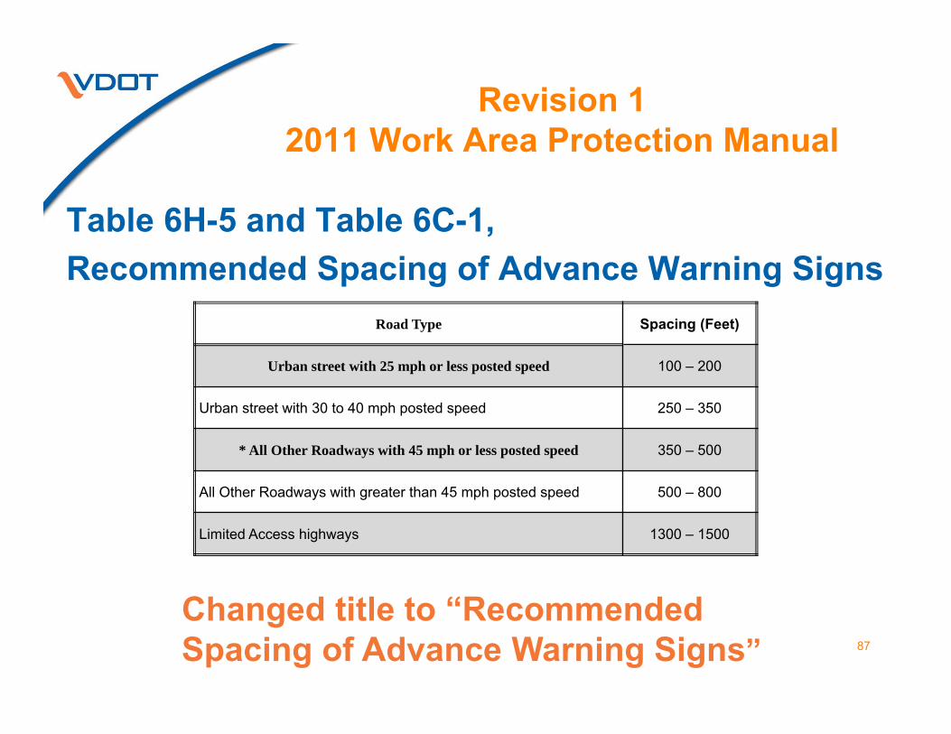
Table 6H-5 and Table 6C-1,Recommended Spacing of Advance Warning Signs
Road Type Spacing (Feet)
Urban street with 25 mph or less posted speed 100 – 200
Urban street with 30 to 40 mph posted speed 250 – 350
* All Other Roadways with 45 mph or less posted speed 350 – 500
All Other Roadways with greater than 45 mph posted speed 500 – 800
Limited Access highways 1300 – 1500
87
Revision 1 2011 Work Area Protection Manual
Changed title to “Recommended Spacing of Advance Warning Signs”

88
Revision 1 2011 Work Area Protection Manual
Chapter 6HFigure 6H-1
TEMPORARY TRAFFIC BARRIER
Changed CONCRETE to
TRAFFIC

89
Revision 1 2011 Work Area Protection Manual
Eliminated STROBE lightas a vehicle warning light in:
Figure Note Number(s) Figure Note Number(s)
TTC-1 Notes 4 & 5 TTC-3 Notes 3 & 4TTC-4 Notes 4 & 5 TTC-5 Notes 5 & 6TTC-9 Note1 TTC-10 Note1TTC-11 Notes 1 & 2 TTC-12 Notes 1 & 2TTC-13 Note 1 TTC-14 Note 1TTC-15 Note 2 TTC-16 Notes 8 & 9TTC-17 Notes 8 & 9 TTC-18 Notes 8 & 9TTC-19 Notes 8 & 9 TTC-20 Note 6TTC-21 Note 6 TTC-22 Note 7

90
Revision 1 2011 Work Area Protection Manual
Eliminated STROBE lightas a vehicle warning light in:
Figure Note Number(s) Figure Note Number(s)TTC-23 Note 7 TTC-24 Note 10TTC-26 Notes 4 & 6 TTC-27 Notes 4 & 6TTC-28 Notes 4 & 5 TTC-31 Notes 7 & 8TTC-32 Notes 3 & 5 TTC-33 Notes 8 & 9TTC-37 Note 7 TTC-38 Note 4TTC-39 Note 8 TTC-40 Note 9TTC-41 Note 7 TTC-42 Note 6TTC-49 Notes 3 & 4 TTC-56 Notes 10 & 11TTC-61 Notes 1 & 4 TTC-62 Note 1

Revision 1 2011 Work Area Protection Manual
Mobile or Short Duration Shoulder OperationTTC-3.1
91
8. A TMA shall be used on Limited Access highways and multi-lane roadway where the posted speed limit is 45 or greater and the work operation last more than 60 minutes.
9. Vehicle warning lights may be used when the work operation is off the shoulder 1 – 15 minutes.
10. A sign should supplement the vehicle warning lights when the work is off the shoulder for 15-60 minutes.

Revision 1 2011 Work Area Protection Manual
92
11. Channelizing devices at a reduced spacing may be used to delineate the work area. They would start at the front of the shadow vehicle & extend through the work area.
Mobile or Short Duration Shoulder OperationTTC-3.1

Revision 1 2011 Work Area Protection Manual
Stationary Operation on a ShoulderTTC-4.1
93
1. Divided highway:For work operations less than 3 days, sign assemblies only required on the side of the shoulder closure.

Revision 1 2011 Work Area Protection Manual
Shoulder Operation with Minor EncroachmentTTC-5.1
94
1. Divided highway:Long-term stationary work left and right sign assemblies required when median is wider than 8'.

Revision 1 2011 Work Area Protection Manual
Shoulder Closure with Barrier OperationTTC-6.1
95
4. Shoulder Taper forLimited Access highway shall be 360 feet otherwise 1/3L on all other roadways.

Revision 1 2011 Work Area Protection Manual
Mowing Operation with Encroachment on Non-Limited Access Roadways - TTC-9.1
96
9. Weed eating and push mowing should be preformed using the mowing series of warning signs.
11. If only litter pick up operation is performed then the LITTER PICK UP signs shall be used.
12. If warning signs for mowing and litter pick up operations cannot be seen by ramp traffic, then warning signs shall be installed on the ramp.

Revision 1 2011 Work Area Protection Manual
Mowing Operation with Encroachment on Non-Limited Access Roadways - TTC-9.1
97
10. Litter pick up may be preformed with the mowing series of warning signs during mowing operations.
13. If only litter pick up operations are performed then the LITTER PICK UP signs shall be used.
14. A shadow vehicle with a TMA may be used behind the slow moving vehicle to protect motorists and the operator.

Revision 1 2011 Work Area Protection Manual
98
15. If only litter pick up operation is performed then the LITTER PICK UP signs shall be used.
16. If warning signs for mowing and litter pick up operations cannot be seen by ramp traffic, then warning signs shall be installed on the ramp.
Non-Licensed Vehicle Operation with Encroachment on Limited Access Highways - TTC-10.1

Revision 1 2011 Work Area Protection Manual
Non-Licensed Vehicle Operation with Encroachment on Limited Access Highways - TTC-10.1
99
13. Weed eating and push mowing should be preformed using the mowing series of warning signs.
14. Litter pick up may be preformed with the mowing series of warning signs during mowing operations.
17. If only litter pick up operations are performed then the LITTER PICK UP signs shall be used.

Revision 1 2011 Work Area Protection Manual
Moving/Mobile Operations on Limited Access Highways (Multiple Lane Closure) - TTC-12.1
100
• In Figure added optional Shadow Vehicle 5
5. Non Limited Access Highways Shadow Vehicle 1 shall have the option to use a PCMS or Arrow Board

Revision 1 2011 Work Area Protection Manual
Short Duration Operation on a Multi-Lane Roadway - TTC-15.1
101
9. Channelizing devices at a reduced spacing may be used to delineate the work area. They would start at the front of the shadow vehicle & extend through the work area.

Revision 1 2011 Work Area Protection Manual
102
TTC-19.1 & TTC-22.15. Corrected
Lane Width (Feet)
TTC-32.14. Corrected
Lane Width (Feet)
TTC-19.1, TTC-22.1 & TTC-32.1

Revision 1 2011 Work Area Protection Manual
Lane Closure Operation with Temporary Traffic Barrier - TTC-20.1
103
Speed Limit (mph)
Flare Rate1
Speed Limit (mph)
Flare Rate1
Speed Limit (mph)
Flare Rate1
70 22:1 55 17:1 40 13:165 20:1 50 16:1 35 11:1 60 19:1 45 14:1 ≤30 10:1
• Title changed Temporary Traffic Barrier8. Change slope rate to Flare Rate in text
and table.

Revision 1 2011 Work Area Protection ManualRight Lane Closure Operation on a
Three-Lane Roadway - TTC-22.1
104
6. Channelizing device spacing shall be a maximum of 20' on center in the buffer & activity area.
10. Four channelizing devices should be used to beyond the downstream end of the transition area as depicted to provide additional guidance for motorists.

Revision 1 2011 Work Area Protection Manual
Lane Closure on a Two-Lane Roadway Using Flaggers - TTC-23.1
105
14. Portable Temporary Rumble Strips (PTRS) when used:• Must be approved by
the Engineer• Installed in conjunction
with BE PREPARED TO STOP sign.
• RUMBLE STRIP AHEAD sign required.
• PTRS Spacing:Posted Speed 0 – 35 mph 36 – 55 mph PTRS Spacing (Center to Center) 5 Feet 8 Feet

Revision 1 2011 Work Area Protection Manual
Lane Closure on a Two-Lane Roadway Using Flaggers - TTC-23.1
106
9. Portable temporary rumble strips (PTRS)should be adjusted when the queue of traffic reaches the BE PREPARED TO STOP sign.

Revision 1 2011 Work Area Protection Manual
107
Lane Closure Operation on a Two-Lane Roadway Using Traffic Control Signals - TTC-25.1
13. Long-term1
rumble strips may be used to enhance the work zone.

Revision 1 2011 Work Area Protection Manual
Lane Closure Operation – Near Side of an Intersection - TTC-26.1
108
8. If the left turn lane is closed a NO LEFT TURN (Symbol) (R3-2) shall be used.
New sign required
R3-20L

Revision 1 2011 Work Area Protection ManualLane Closure Operation - Far Side of
an Intersection - TTC-27.1
109
8. If the left turn lane is closed a NO LEFT TURN (Symbol) (R3-2) shall be used.
New sign required
R3-20L

Revision 1 2011 Work Area Protection Manual
110
Turn Lane Closure OperationTTC-29.1
Posted Speed Limit (mph) Distance (Feet)1
≤20 115 – 12025 155 – 16530 200 – 21035 250 – 26040 305 – 32545 360 – 38050 425 – 44555 500 – 53060 570 – 60065 645 – 67570 730 – 760
7. Changed buffer space lengths:

Revision 1 2011 Work Area Protection Manual
Flagging Operation at a Signalized Intersection - TTC-30.1
111
Notes 3 & 4 –When FLAGGERS control a signalized intersection. • Turn lanes are closed. • Lane closures are
installed on a multi-lane roadways.
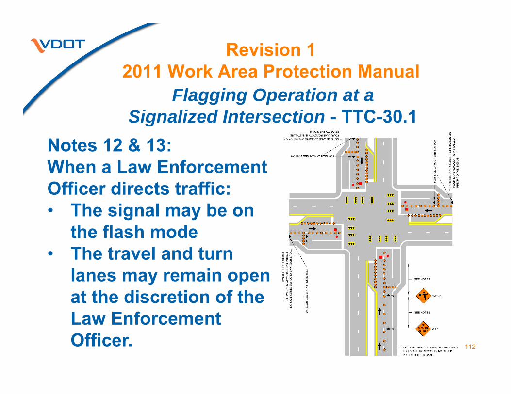
Revision 1 2011 Work Area Protection Manual
Flagging Operation at a Signalized Intersection - TTC-30.1
112
Notes 12 & 13:When a Law Enforcement Officer directs traffic: • The signal may be on
the flash mode• The travel and turn
lanes may remain open at the discretion of the Law Enforcement Officer.

Revision 1 2011 Work Area Protection Manual
Street Closure Operation with Detour -TTC-34.1
113
Changed NO RIGHT TURN to

Revision 1 2011 Work Area Protection Manual
Crosswalk Closure and Pedestrian Detour Operation - TTC-36.1
114
10. Motorists shall yield to pedestrians
• 24" x 36" yield lines required

Revision 1 2011 Work Area Protection Manual
Work Operation in the Vicinity of an Exit Ramp -TTC-37.1
115
4. EXIT OPEN, EXIT w/ ARROW, EXIT Closed signs shall be a min of 7' from pavement surface to bottom of the sign

Revision 1 2011 Work Area Protection Manual
Work Operation in the Vicinity of an Exit Ramp -TTC-37.1
116
Figure:• Adjusted “L”
• Added “1 MILE” distance in advance of warning signs
• Added PCMS & 4 drum taper

Revision 1 2011 Work Area Protection Manual
117
Work Operation in the Vicinity of an Entrance Ramp - TTC-39.1
4. STOP and YIELD signs shall be mounted a minimum of 7 feet from the pavement surface tothe bottom of the sign.

Revision 1 2011 Work Area Protection Manual
118
Interior Lane Closure Operation on a Multi-Lane Roadway - TTC-42.1
9. Four channelizing devices should be used to beyond the downstream end of the transition area.
10. NO LEFT TURN should be use when high volume turning movement exists.

Revision 1 2011 Work Area Protection Manual
Road Closure Operation with a Diversion TTC-43.1
119
In figure:• Added Chevrons• Added two-way
pavement markers throughout diversion

Revision 1 2011 Work Area Protection ManualMedian Cross-Over Operation on a Multi-Lane Roadway TTC-44.1
120
Optional or required Ty. 3 Barricade
Temporary pavement markers required in merging and shifting tapers

Revision 1 2011 Work Area Protection Manual
Total Limited Access Highway Closure Operation - TTC-45.1
121
Added to Figure a 4 drum taper for the PCMS

Revision 1 2011 Work Area Protection Manual
Limited Access Highway Closure Operation with a Short Term Detour - TTC-46.1
122
Changed stripesof Ty. 3 Barricade

Revision 1 2011 Work Area Protection Manual
Limited Access Highway Closure Operation with a Long Term Detour - TTC-47.1
123
• Changed stripesof Ty. 3 Barricade
• All directional arrows shall be fluorescent orange

Revision 1 2011 Work Area Protection Manual
Road Closure Operation with a DetourTTC-48.1
124
• Changed stripesof Ty. 3 Barricade
• All directional arrows shall be fluorescent orange
• Changed sign designations
• Add confirmation detour or route shield assembly and distance from intersection.

Revision 1 2011 Work Area Protection Manual
Surveying Operation - TTC-49.1
125
• Change work area to work space
• Defines maximum work space as 2 miles

Revision 1 2011 Work Area Protection Manual
Haul Road Crossing Operation - TTC-51.1
126
Added titles to Figure:• SIGNALIZED METHOD• FLAGGER METHOD

Revision 1 2011 Work Area Protection Manual
Signing for Speed Limit and Fine Signs in Work Zones - TTC-52.1
127
1. A Traffic Engineering (TE) investigation shall be performed and evaluated to reduce the speed limit per TE-350 Memo.
5. When the WORK ZONE $500 MAX FOR EXCEEDING SPEED LIMIT WHEN FLASHING sign is used Type B warning lights shall be installed above the sign and shall be controlled remotely and activated when workers are present in the work zone.

Revision 1 2011 Work Area Protection Manual
Signing for Speed Limit and Fine Signs in Work Zones - TTC-52.1
128
5. When the WORK ZONE $500 MAX FOR EXCEEDING SPEED LIMIT WHEN FLASHING is used the WORK ZONE plaque shall be installed above the SPEED LIMIT sign and the FINES HIGHER plaque below.

Revision 1 2011 Work Area Protection Manual
Signing for Speed Limit and Fine Signs in Work Zones - TTC-52.1
129
10. Speed Limits may be reduced for short-term (less than 72 hours) operations• If the speed limit is reduced portable
sign supports may be used for the Reduced Speed Limit Ahead graphic an the SPEED LIMIT signs

Revision 1 2011 Work Area Protection Manual
130
7. END WORK ZONE SPEED LIMIT only required on road without a posted speed limit
In figure:• Added or deleted
reference notes for sign• Change WORK ZONE
MAX FINE sign and added Ty. B Warning Lights
Signing for Speed Limit and Fine Signs in Work Zones - TTC-52.1

Revision 1 2011 Work Area Protection Manual
131
Eradication of Pavement Markings in a Work Zone - TTC-55.1
4. In lane shift areas pavement markings and markers shall be removed when:• not behind temporary traffic barrier• within 6' of the new edge line
8. Addition pavement markings & pavement markers should be removed based on roadway geometrics & specific site conditions so traffic is guided safely in case TTC devices become displaces.

Revision 1 2011 Work Area Protection Manual
End of Day Signing for Partial Paving Operations on a Multi-Lane Roadway - TTC-57.1 &
End of Day Signing for Full Paving Operations on a Multi-Lane Roadway - TTC-58.1
132
7. Portable sign supports shall be supported by a sand bag weighing approximately 25-pounds on each leg or two (2) drum collar weights positioned on the center of the sign stand for:

Revision 1 2011 Work Area Protection Manual
133
End of Day Signing for Paving Operations on a Two-Lane Roadway - TTC-59.1
4. & 6.:Portable sign supports shall be supported by a sand bag weighing approximately 25-pounds on each leg or two (2) drum collar weights positioned on the center of the sign stand for:

Revision 1 2011 Work Area Protection Manual
134
End of Day Signing for Paving Operations on a Two-Lane Roadway - TTC-59.1
9. Other devices may be need to control traffic through work area.
10. LOW SHOULDER sign may be used where there is an elevation difference of less than 2 inches between the shoulder and travel lane.

Revision 1 2011 Work Area Protection Manual
End of Day Signing for Paving Operations on a Two-Lane Roadway - TTC-59.1
135
8. Added sign spacing distances.
In Figure changed note references for: • Begin & end
pavement drop-off• Sign spacing

136
Revision 1 2011 Work Area Protection Manual
4. Logging operations Truck Entering Highway shall be used.LOG TRUCKS ENTERING HIGHWAY sign shall not be use.
Logging Operations - TTC-63.1

Revision 1 2011 Work Area Protection Manual
137
NEW - End of Day Signing for Surface Treatment, Slurry Seal and Latex Emulsion Treatment
Operations - TTC-64.0Standard:1. LOOSE GRAVEL (W8-7) signs shall be installed on surface treated roadways and shall be
removed when the roadway has been swept or loose gravels have been removed from the roadway.
2. NO CENTER LINE (W8-12) signs shall be installed whenever the centerline has been obliterated or until permanent pavement markings have been installed. The sign shall be installed in both directions when the centerline is not present. In addition, NO CENTER LINE signs shall be installed every mile if the unmarked area is less than 3 miles, or every 2 miles if the unmarked area is longer than 4 miles.
3. A DO NOT PASS (R401) sign shall be used when the centerline has been obliterated or until permanent pavement markings have been installed. The DO NOT PASS sign shall be installed after the NO CENTER LINE sign and their sign stand shall be supported with a sand bag weighting approximately 25-pounds on each leg or two (2) drum collar weights positioned on the center of the sign stand. Thereafter, the DO NOT PASS sign installed every mile if the unmarked area is less than 3 miles, or every 2 miles if the unmarked area is longer than 4 miles.
4. Signs shall be post-mounted at locations after 72 consecutive hours of non-work activities.5. If temporary construction or permanent pavement markings cannot be installed in
accordance with Road and Bridge Specification 704, then yellow flexible temporary pavement markers (FTPMs) spaced at 20-foot centers for two-way traffic shall be placed along the centerline for lane division. No edge markers will be required.
Guidance:6. Sign spacing distance should be 350'-500' where the posted speed limit is 45 mph or less, 500'-
800' where the posted speed limit is greater than 45 mph.Option7. Only traffic control signing for surface treatment/slurry/latex emulsion treatment operations is
shown. Other traffic control; devices may be used for the control of traffic through the work area.
8. The advanced warning signs shown may also be used on multi-lane roadways, replacing the NO CENTER LINE signs with UNMARKED PAVEMENT AHEAD (W8-V4) signs and adding a ROAD WORK AHEAD (W20-1) sign as the first advanced warning sign.

Revision 1 2011 Work Area Protection Manual
138
NEW - Short Duration Road Patching Operation on a Low Volume Two-Lane Roadway -TTC-65.0
Guidance:1. Sign spacing distance should be 350'-500' where the posted speed limit 45 mph or less, and 500'-800' where the posted
speed limit is greater than 45 mph.Standard:2. A ROAD PATCHING NEXT 5 MILES (W21-V19) sign, a BE PREPARED TO STOP (W3-4) sign and a Flagger
(W20-7) symbol sign shall be installed at the intersection of each end of the route being patched. See Figure TTC-67 for guidance on the requirements for intersections within the limits of the operation.
3. Flagging Station Options:A. A single flagger can be used when adequate sight distance is available from both travel directions;B. When adequate sight distance is not available to utilize a single flagger, traffic shall be stopped in the direction of
the work vehicles until work is completed. C. When adequate sight distance is not available to use a single flagger to control two-way traffic, two flaggers shall
be used to control the two-way traffic until the work is complete.4. Each vehicle involved in the moving/mobile operation shall be equipped with at least one high-intensity amber
rotating, oscillating, or flashing light. Vehicle hazard warning signals shall not be used instead of rotating lights or flashing lights, but as a supplement.
5. If using a Type B (60" x 30") or Type C (96" x 48") arrow board on the shadow vehicle, it shall operate in the four corner caution mode.
Guidance: 6. When using a CMS to replace the arrow board it should display the Type B caution mode.7. Care should be exercised when establishing the flagger station to insure maximum possible sight distance based on the
posted speed limit and at least equal to or greater than the values in Table 6H-3.8. Where practical and when needed, the work and shadow vehicles should pull over periodically to allow motor vehicle traffic
to pass.9. Whenever adequate stopping sight distance exists to the rear, the shadow vehicle should maintain the minimum distance
from the work vehicle/operation and proceed at the same speed. The shadow vehicle should slow down or stop if necessary in advance of vertical or horizontal curves that restrict sight distance.
10. A truck-mounted attenuator should be used on the shadow vehicle.Option:11. A ROAD PATCHING NEXT 2 MILES (W21-V19) sign or ROAD PATCHING AHEAD (W21-V18) sign may be used to
meet field condition.12. The distance between the work and shadow vehicles may vary according to speed, terrain, curing time and other factors.13. A PCMS may be used in advance of the work operation to supplement the static advance warning signs.14. The vehicle mounted arrow board may be replaced with a vehicle-mounted CMS with a minimum character height of 10".

Revision 1 2011 Work Area Protection Manual
139
NEW - Slow Roll Operation on a Multi-Lane Roadway - TTC-66.0
Standard:1. Slow Roll operation shall be submitted to and approved by the Regional Traffic Engineer or their designee prior to
use and shall be performed according to Section 6G.24.2. Slow Roll operation shall include the use of the Virginia State Police (VSP) or other law enforcement personnel
unless an exception is granted by the Regional Traffic Engineer.3. A portable changeable message sign (PCMS) or, if available, an overhead changeable message sign (CMS) shall be
used a minimum of 1 mile in advance of the beginning of the Slow Roll operation with the following messages: ROAD WORK AHEAD; BE PREPARED TO STOP.
4. A control vehicle (contractor or state) shall occupy each travel lane of the route affected by the Slow Roll operation. All entrance ramps within the Slow Roll operation shall be temporarily closed. A drive through of the route shall be performed prior to beginning the Slow Roll operation to ensure there are no parked vehicles along the roadway which could enter the travel lane during the Slow Roll operation.
Option5. Once the Slow Roll operation has passed a closed entrance ramp, the ramp may be reopened.Standard:6. Prior to utilizing Slow Roll operation, a coordination meeting shall be held with all entities involved in the operation
to discuss each person’s role.7. The starting point for the Slow Roll operation shall be in a tangent section (both horizontal and vertical) of the
approach roadway with adequate sight distance.8. Law enforcement vehicles in the Slow Roll operation shall display full emergency lights.9. Each slow roll control vehicle shall be equipped with at least one high-intensity amber rotating, oscillating, or
flashing light. Vehicle hazard warning signals shall not be used instead of rotating lights or flashing lights, but as a supplement.
10. Each slow roll control vehicle shall be equipped with a Type C (96" x 48") arrow board on the shadow vehicle, it shall operate in the four corner caution mode.
11. Each slow roll control vehicle controlling traffic shall be equipped with a truck- mounted attenuator.12. Upon a sufficient gap in traffic, each slow roll vehicle will pull out and occupy a travel lane with their warning
lights and hazard lights operating and will travel at a minimum of 10 miles per hour. A lead vehicle shall follow the last motorist vehicle traveling in advance of the slow roll operation vehicles to notify the work crew when the roadway is closed and free of approaching motorist.
13. The lead vehicle in the Slow Roll operation shall have radio/telephone communication with the work crew. Once the need for the road closure is complete, the work crew shall notify the lead vehicle in the slow roll operation, who in turn will notify the other work vehicles. The slow roll vehicles shall gain speed and pull over to the right side of the roadway; starting from the vehicle occupying the left lanes first (the VSP should continue with the flow of traffic).
14. If the Slow Roll operation vehicles reach the work site before receiving notification that the operation has been completed, they shall slow down and/or stop until signaled that the roadway is safe to release traffic.
15. Once the Slow Roll operation is complete and free flow travel conditions have been re-established, the PCMS or overhead CMS messages shall be modified to remove the BE PREPARED TO STOP message.

Revision 1 2011 Work Area Protection Manual
NEW - Lane Closure Operation through an Unsignalized Intersection - TTC-67.0)
140
Guidance:1. Sign spacing distance should be 350'-500' where the posted speed limit is 45 mph or less, 500'-800'
where the posted speed limit is greater than 45 mph.Standard:2. Channelizing device spacing shall be on 20' centers or less 100 feet in advance of the
intersection.Guidance:3. If room permits, a shadow vehicle with at least one rotating amber light or high intensity amber strobe
light should be parked 80'-120' in advance of the first work crew.4. If the posted speed limit is 45 mph or greater, the shadow vehicle should have a truck-mounted
attenuator.5. If the work space extends across a crosswalk, the crosswalk should be closed using the information
and devices shown in Figure TTC-36.Option6. At the stop condition intersecting roadway, additional flagger sign may be used (BE PREPARED TO
STOP (W3-4)) between the ROAD WORK AHEAD and the flagger station in the proper sequence, as directed by the Regional Traffic Engineer.

CHAPTER 6I CONTROL OF TRAFFIC
THROUGH TRAFFIC INCIDENT
MANAGEMENT AREAS
141
Revision 1 2011 Work Area Protection Manual
A number represent TTC note.

Revision 1 2011 Work Area Protection Manual
Chapter 6I
5. Change Buffer Space Table in:• TIMC-1.1• TIMC-2.1• TIMC-3.1• TIMC-4.1
142
Posted Speed Limit (mph) Distance (Feet) ≤ 20 115 - 120 25 155 - 1651 30 200 - 210 35 250 - 260 40 305 - 3251 45 360 - 380 50 425 - 445 55 500 - 5301 60 570 - 6001 65 645 – 675 70 730 - 760
Vehicles and equipment shall not park in the buffer space.

143
Revision 1 2011 Work Area Protection Manual
9. Eliminated STROBE light as a vehicle warning light
Incident Blocking a Lane on a Two-Lane RoadwayTIMC-7.1

Revision 1 2011 Work Area Protection Manual
Incident Closing a HighwayTIMC-7.1
144
6. Added:• see Figures TTC-
46 or TTC-47.• Detour with a
Route Assembly sign.

Revision 1 2011 Work Area Protection Manual
Highway Closure Incident with a Temporary Detour - TIMC-8.1
145
Changed stripesof Ty. 3 Barricade

APPENDIX A
GUIDELINES FOR THE USE OF BARRIER/CHANNELIZING
DEVICES IN WORK ZONES
146
Revision 1 2011 Work Area Protection Manual

Revision 1 2011 Work Area Protection Manual
Appendix A1. Channelizing Device/Barrier Selection Process
147
Page A-5:2. Change Figure 3b, ROR Frequency Factor
Chart for All Other Highways to “Figure 3a, ROR Frequency Factor Chart for Limited Access Highways”
Figure 3a added note under title:“Data presented is for 2 way ADT. When applying this chart to divided roadways, reduce ADT by one-half before entering chart.”

Revision 1 2011 Work Area Protection Manual
Appendix A1. Channelizing Device/Barrier Selection Process
148
Page A-6:• Changed Figure 4 to “Table 1”
• Figure 3b added note under title:“Data presented is for 2 way ADT. When applying this chart to divided roadways, reduce ADT by one-half before entering chart.”

Revision 1 2011 Work Area Protection Manual
Appendix A3. BARRIER DESIGN CONSIDERATIONS
149
Page A-14ADDED:Temporary Longitudinal Steel Barriers1
Acceptance based on the following NCHRP 350/Mash08 Test Criteria
Dynamic deflection is based on:¾ Ton pick-up truck at 45 mph and 25°impact angle (TL-2). ¾ Ton pick-up truck at 62 mph and 25°impact angle (TL-3).
For additional information on longitudinal steel barriers, length of need and impact attenuator application, please refer to IIM-LD-93, Construction Work Zone/ Safety Guidelines and Pay Items for Construction Work Zone: http://www.extranet.vdot.state.va.us/locdes/electronic%20pubs/iim/IIM93.pdf

Revision 1 2011 Work Area Protection Manual
Appendix A3. Barrier Design Considerations
150
Page A-14 - Added Table 3, Acceptable Longitudinal Steel Barriers
FHWA Code Manufacturer Device Description Test
LevelDynamic
Deflection Anchorage
B134 Energy Absorption Systems, Inc. Vulcan Barrier TL-3 13'- 2" 302' Lg. (a)
B134 Energy Absorption Systems, Inc.
Vulcan Barrier with Anchoring System VAS TL-3 6'- 11" (b)
B-131 Highway Care, Inc. Barrier Guard 800 TL-3 4'- 11" (c)
B-158 Highway Care, Inc. Barrier Guard 800 MDS TL-3 0'- 3" (d)
B-176A Hill & Smith, Inc. Zone Guard Standard TL-3 6'- 4" (e)
B-176A Hill & Smith, Inc. Zone Guard Minimum Deflection TL-3 1'- 4" (f)
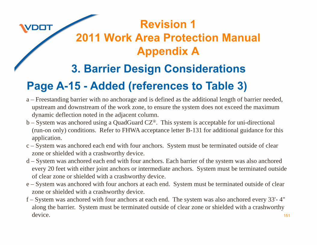
Revision 1 2011 Work Area Protection Manual
Appendix A3. Barrier Design Considerations
Page A-15 - Added (references to Table 3)
151
a – Freestanding barrier with no anchorage and is defined as the additional length of barrier needed, upstream and downstream of the work zone, to ensure the system does not exceed the maximum dynamic deflection noted in the adjacent column.
b – System was anchored using a QuadGuard CZ®. This system is acceptable for uni-directional (run-on only) conditions. Refer to FHWA acceptance letter B-131 for additional guidance for this application.
c – System was anchored each end with four anchors. System must be terminated outside of clear zone or shielded with a crashworthy device.
d – System was anchored each end with four anchors. Each barrier of the system was also anchored every 20 feet with either joint anchors or intermediate anchors. System must be terminated outside of clear zone or shielded with a crashworthy device.
e – System was anchored with four anchors at each end. System must be terminated outside of clear zone or shielded with a crashworthy device.
f – System was anchored with four anchors at each end. The system was also anchored every 33'- 4" along the barrier. System must be terminated outside of clear zone or shielded with a crashworthy device.

Revision 1 2011 Work Area Protection Manual
Appendix A3. Barrier Design ConsiderationsPage A-15 - Added Table 4, Acceptable Longitudinal Channelizing Devices
152
FHWA Code Manufacturer Device Description Test
LevelDynamic
Deflection Anchorage
B111 Creative Building Products Water Filled Plastic Barrier. TL-2 10'- 4"
16' - 6'' Lg. Segments
(96')
B101 Rhino Safety Barrier LLC Water-Filled Plastic Barrier. TL-2 13'- 2" 59'
B-97 Yodock Wall Company, Inc.
Yodock Model 2001M/2001Plastic Barriers w/ steel tubes.
TL-2TL-3
12'14' 46'
B-48 Energy Absorption Systems, Inc.
Triton water-filled temporary barrier. TL-3 19'- 0"
22'- 8"97' - 6"
65'
B-34B-30
Armorcast Products Co. Guardian Safety Barrier System TL-3
TL-211'- 2"6'- 6" (a)

Revision 1 2011 Work Area Protection Manual
Appendix A
Figure 5, Construction Access Technique and Introduced Barrier
Added Ty. 3 Barricade & DO NOT ENTER sign at construction access & work entrances
153

APPENDIX DPORTABLE CHANGEABLE
MESSAGE SIGN (PCMS) DISPLAYS
154
Revision 1 2011 Work Area Protection Manual

Revision 1 2011 Work Area Protection Manual
Appendix D
Page D-1
155
• The revision to Appendix D provides uniformity across the Commonwealth by standardizing PCMS messages for temporary traffic control applications as shown in Chapter 6H.
• Three phase may be displayed on a PCMS but the use of 2 PCMSs is preferred. The Engineer will provide guidance.

Revision 1 2011 Work Area Protection Manual
Appendix D
Page D-1
156
• The revision to Appendix D provides uniformity across the Commonwealth by standardizing PCMS messages for temporary traffic control applications as shown in Chapter 6H.
• Three phase may be displayed on a PCMS but the use of 2 PCMSs is preferred. The Engineer will provide guidance.

Revision 1 2011 Work Area Protection Manual
Appendix DPage D-1
157
PCMS use on long-term projects:• should be used to advise motorists of the
initial change in traffic pattern.• should only display the initial message
should for 2 weeks to retain its effectiveness.• may display daily standardized messages
based on the TTC application that affect the mainline traffic.
• non-standardized messages should be approved by the Regional Traffic Operations Manager, authority of a public agency or official having jurisdiction.

Revision 1 2011 Work Area Protection Manual
Appendix DPage D-2, Alternate Route Messages
158
PCMS should only be used:• where the CMS operator has current and
continuously updated knowledge of the traffic conditions on the alternative route.
• where the alternate route will result in a significant savings in time for the detoured motorists.

Revision 1 2011 Work Area Protection Manual
Appendix DPage D-2, Traffic Detour Messages
159
• PCMS messages should be used when a complete road closure is required.
• A detour is warranted when positive guidance is provide to motorist by:• a properly marked detour or guide signs
to the major destination, or• law enforcement or traffic control
personnel control and guide traffic at critical locations.

Revision 1 2011 Work Area Protection Manual
Appendix DPages D-3 to D-6Table D-1, PCMS Message for
TTC Applications
160

Revision 1 2011 Work Area Protection Manual
Appendix D
161
Page D-6Display of Future Roadwork:• may be displayed• shall be replaced by current information• should not be given more than six (6)
days prior to roadwork• should display the days of the week• may display be a that requires calendar
dates under special situation

Revision 1 2011 Work Area Protection Manual
Appendix D
162
Page D-7Table D-2, Portable Changeable Messages for Advance Closures or Road Work
?? ST / CLOSED / 7/1-8/31RT 50 / CLOSED / MON-FRI
EXIT 123 / CLOSED / JUL14-18RD WORK / CLOSED / MON-FRI
----------

Revision 1 2011 Work Area Protection Manual
Appendix D
163
Page D-7Table D-3, Unacceptable Portable Changeable Messages
BEAWARE, BEWAREBE ALERT (any form or combination of BE ALERT messages)
CARE (any form or combination of CARE messages)USE CARE
CAUTION (any form or combination of CAUTION messages)USE CAUTION
NOTICE (messages)WARNING, WARN (any form or combination of WARN messages)
----------

Revision 1 2011 Work Area Protection Manual
Appendix D
164
Pages D-8 to D-9, Table D-4, Abbreviations That Shall be
Used Only on PCMS Signs

Revision 1 2011 Work Area Protection Manual
Appendix D
165
Page D-10 Table D-5, Acceptable Abbreviations• Word abbreviations shown shall be used
when necessary.• Abbreviations should either precedes or
follow prompt word shown.

Revision 1 2011 Work Area Protection Manual
Appendix D
166
Page D-11 Table D-6, Unacceptable AbbreviationsAbbreviations that shall not be used because of their potential to be misinterpreted by road users.

Revision 1 2011 Work Area Protection Manual
167
• Effective April 1, 2015 for State Forces
• Effective starting on the July 2015 Advertisement