revision record for the state of california … cmc supplement.pdf · revision record . for the...
TRANSCRIPT

REVISION RECORD FOR THE STATE OF CALIFORNIA
SUPPLEMENT
July 1, 2018
2016 Title 24, Part 4 California Mechanical Code
General Information: 1. The date of this Supplement is for identification purposes only. See the History Note
Appendix on the backside or accompanying page. 2. This supplement is issued by the California Building Standards Commission in order to
provide new and/or replacement pages containing recently adopted provisions for California Code of Regulations, Title 24, Part 4, of the 2016 California Mechanical Code. Instructions are provided below.
3. Health and Safety Code Section 18938.5 establishes that only building standards in effect
at the time of the application for a building permit may be applied to the project plans and construction. This rule applies to both adoptions of building standards for Title 24 by the California Building Standards Commission, and local adoptions and ordinances imposing building standards. The new building standards provided with the enclosed blue supplement pages must not be enforced before the effective date.
4. Not all code text on the enclosed blue supplement pages is a new building standard. New,
amended, or repealed building standards are identified by margin symbols. An explanation of margin symbols is provided in the code before the Table of Contents.
5. You may wish to retain the superseded material with this revision record so that the prior
wording of any section can be easily ascertained.
Title 24, Part 4
Remove Existing Pages
xxvii – xxx 1 – 2
27 – 28 45 – 46 55 – 56 61 – 80
81 – 84
105 – 106 491 – 492
Insert Blue-Colored Pages
xxvii – xxx
1 – 2 27 – 28 45 – 46 55 – 56 61 – 80
80.1 – 80.2 81 – 84
105 – 106 491 – 492


xxvii2016 CALIFORNIA MECHANICAL CODE
308.1 General . . . . . . . . . . . . . . . . . . . . . . 52
309.0 Workmanship . . . . . . . . . . . . . . . . . 52
309.1 Engineering Practices. . . . . . . . . . . 52
309.2 Concealing Imperfections . . . . . . . . 52
309.3 Installation Practices. . . . . . . . . . . . 52
310.0 Condensate Wastesand Control . . . . . . . . . . . . . . . . . . . 52
310.1 Condensate Disposal . . . . . . . . . . . 52
310.2 Condensate Control . . . . . . . . . . . . 52
310.3 Condensate Waste Pipe Material and Sizing. . . . . . . . . . . . . 52
Table 310.3 Minimum CondensatePipe Size . . . . . . . . . . . . . . . . . . . . 52
310.4 Appliance Condensate
Drains . . . . . . . . . . . . . . . . . . . . . . . 53
310.5 Point of Discharge . . . . . . . . . . . . . 53
310.6 Condensate Waste From Air-Conditioning Coils . . . . . . . . . . . 53
310.7 Plastic Fittings. . . . . . . . . . . . . . . . . 53
311.0 Heating or Cooling AirSystem . . . . . . . . . . . . . . . . . . . . . . 53
311.1 Source . . . . . . . . . . . . . . . . . . . . . . 53
311.2 Air Filters. . . . . . . . . . . . . . . . . . . . . 53
311.3 Prohibited Source . . . . . . . . . . . . . . 53
311.4 Return-Air Limitations . . . . . . . . . . . 53
312.0 Plumbing Connections . . . . . . . . . . 53
312.1 General . . . . . . . . . . . . . . . . . . . . . . 53
313.0 Hangers and Supports . . . . . . . . . . 54
313.1 General . . . . . . . . . . . . . . . . . . . . . . 54
313.2 Material . . . . . . . . . . . . . . . . . . . . . . 54
313.3 Suspended Piping . . . . . . . . . . . . . 54
313.4 Alignment . . . . . . . . . . . . . . . . . . . . 54
313.5 Underground Installation. . . . . . . . . 54
313.6 Hanger Rod Sizes . . . . . . . . . . . . . 54
Table 313.6 Hanger Rod Sizes . . . . . . . . . . . . . 54
313.7 Gas Piping . . . . . . . . . . . . . . . . . . . 54
314.0 Balancing . . . . . . . . . . . . . . . . . . . . 54
314.1 General . . . . . . . . . . . . . . . . . . . . . . 54
315.0 Louvers in Hurricane Prone Regions . . . . . . . . . . . . . . . . 54
315.1 General . . . . . . . . . . . . . . . . . . . . . . 54
316.0 Protection of Piping, Tubing, Materials, and Structures . . . . . . . . 54
316.1 General . . . . . . . . . . . . . . . . . . . . . . 54
316.2 Installation . . . . . . . . . . . . . . . . . . . 54
316.3 Corrosion, Erosion, andMechanical Damage. . . . . . . . . . . . 54
316.4 Protectively Coated Pipe. . . . . . . . . 54
316.5 Fire-Resistant Construction . . . . . . 54
316.6 Steel Nail Plates . . . . . . . . . . . . . . . 54
316.7 Sleeves . . . . . . . . . . . . . . . . . . . . . . 54
316.8 Firewalls . . . . . . . . . . . . . . . . . . . . . 55
316.9 Structural Members . . . . . . . . . . . . 55
316.10 Rodentproofing . . . . . . . . . . . . . . . . 55
316.11 Metal Collars. . . . . . . . . . . . . . . . . . 55
317.0 Trenching, Excavation, and Backfill . . . . . . . . . . . . . . . . . . . 55
317.1 Trenches . . . . . . . . . . . . . . . . . . . . . 55
317.2 Tunneling and Driving. . . . . . . . . . . 55
317.3 Open Trenches . . . . . . . . . . . . . . . . 55
317.4 Excavations. . . . . . . . . . . . . . . . . . . 55
318.0 Scope . . . . . . . . . . . . . . . . . . . . . . . 55
318.1 Applicability. . . . . . . . . . . . . . . . . . . 55
318.2 Services/Systems andUtilities . . . . . . . . . . . . . . . . . . . . . . 55
319.0 Steam and Hot-WaterSystems . . . . . . . . . . . . . . . . . . . . . 55
319.1 Requirements for Hospitals and Optional Services Providedin Correctional TreatmentCenters . . . . . . . . . . . . . . . . . . . . . . . 55
319.2 Requirements for Skilled Nursing, Intermediate Care Facilities and Basic ServicesProvided in Correctional Treatment Centers . . . . . . . . . . . . . 55
320.0 Air Conditioning and Heating Systems. . . . . . . . . . . . . . . 56
320.1 Requirements for Hospitals and Optional Services Provided in Correctional Treatment Centers. . . . . . . . . . . . . . . 56
320.2 Requirements forSkilled Nursing, IntermediateCare Facilities and BasicServices Provided inCorrectional TreatmentCenters . . . . . . . . . . . . . . . . . . . . . . 56
320.3 Requirements for OutpatientFacilities and Licensed Clinics . . . . . . . . . . . . . . . . . . . . . . . 56
320.4 Telephone and DataEquipment Rooms . . . . . . . . . . . . . 56
320.5 Psychiatric Services . . . . . . . . . . . . 56
321.0 Essential Mechanical Provisions . . . . . . . . . . . . . . . . . . . . 56
322.0 Sensitive Areas or Rooms . . . . . . . 56
Table 303.10.1 Reduction of Clearanceswith Specified Forms or Protection . . . . . . . . . . . . . . . . . . 57
Table 313.3 Hangers and Supports . . . . . . . . . . 59
JULY 1, 2018 SUPPLEMENTBLUE

xxviii 2016 CALIFORNIA MECHANICAL CODE
CHAPTER 4 VENTILATION AIR. . . . . . . . . . . . . 61
401.0 General . . . . . . . . . . . . . . . . . . . . . . 63
401.1 Applicability. . . . . . . . . . . . . . . . . . . 63
402.0 Ventilation Air . . . . . . . . . . . . . . . . . 63
402.1 Occupiable Spaces. . . . . . . . . . . . . 63
402.2 Natural Ventilation. . . . . . . . . . . . . . 63
402.3 Mechanical Ventilation . . . . . . . . . . 64
402.4 Outdoor AirIntake Protection . . . . . . . . . . . . . . . 64
402.5 Bathroom Exhaust Fans . . . . . . . . . 64
403.0 Ventilation Rates. . . . . . . . . . . . . . . 64
403.1 General . . . . . . . . . . . . . . . . . . . . . . 64
403.2 Zone Calculations. . . . . . . . . . . . . . 64
403.3 Single-Zone Systems . . . . . . . . . . . 64
403.4 One Hundred Percent Outdoor Air Systems. . . . . . . . . . . . 64
403.5 Multiple-Zone Recirculating Systems . . . . . . . . . . 64
403.6 Design for Varying Operating Conditions . . . . . . . . . . . 65
403.7 Exhaust Ventilation . . . . . . . . . . . . . 65
403.8 Dynamic Reset . . . . . . . . . . . . . . . . 66
403.9 Air Classification and Recirculation . . . . . . . . . . . . . . 66
404.0 Multiple-Zone Systems . . . . . . . . . . 66
404.1 General . . . . . . . . . . . . . . . . . . . . . . 66
404.2 Average OutdoorAir Fraction . . . . . . . . . . . . . . . . . . . 66
404.3 Zone Ventilation Efficiency . . . . . . . 66
405.0 Evaporative Cooling Systemfor Health Care Facilities . . . . . . . . . 67
406.0 Reserved . . . . . . . . . . . . . . . . . . . . . 67
407.0 Ventilation System Details . . . . . . . . 67
407.1 General. . . . . . . . . . . . . . . . . . . . . . . 67
407.2 Outdoor Air Intakes andExhaust Outlets . . . . . . . . . . . . . . . . 67
407.3 Air Balance . . . . . . . . . . . . . . . . . . . . 68
407.4 Air Circulation . . . . . . . . . . . . . . . . . . 68
407.5 Variable Air Volume . . . . . . . . . . . . . 68
408.0 Filters . . . . . . . . . . . . . . . . . . . . . . . . 69
408.1 General. . . . . . . . . . . . . . . . . . . . . . . 69
408.2 Filters for Hospital. . . . . . . . . . . . . . . 69
408.3 Filters for Skilled Nursing Facilities, Intermediate Care Facilties, and CorrectionalTreatment Centers . . . . . . . . . . . . . 69
408.4 Filters for Outpatient Facilities . . . . 69
409.0 Ducts. . . . . . . . . . . . . . . . . . . . . . . . 69
409.3 Insulation of Ducts . . . . . . . . . . . . . 69
410.0 Laboratory Ventilating Systemsand Hoods . . . . . . . . . . . . . . . . . . . 70
410.1 Laboratory Ventilating Systems . . . 70
410.2 Exhaust Hoods and SafetyCabinets . . . . . . . . . . . . . . . . . . . . . 70
410.3 Laboratory Fume Hoods. . . . . . . . . 70
411.0 Kitchen and Dining Areas . . . . . . . . 70
412.0 Boiler, Mechanical, and Electrical Rooms. . . . . . . . . . . . . . . 70
413.0 Odorous Rooms . . . . . . . . . . . . . . . 70
414.0 Airborne Infection IsolationsRooms . . . . . . . . . . . . . . . . . . . . . . 70
414.1 Exhaust Systems . . . . . . . . . . . . . . 70
414.2 Air Distribution . . . . . . . . . . . . . . . . 71
415.0 Protective Environment Rooms. . . . 71
415.1 Air Distribution . . . . . . . . . . . . . . . . 71
416.0 Alarms – Airborne InfectionIsolation Rooms and ProtectiveEnvironment Rooms . . . . . . . . . . . . 71
417.0 Testing and Balancing AirborneInfection Isolation Roomsand Protective Environment Rooms . . . . . . . . . . . . . . . . . . . . . . 71
418.0 Design Requirements for Ethylene Oxide (ETO) Sterilization Areas. . . . . . . . . . . . . . 71
418.1 Air Changes . . . . . . . . . . . . . . . . . . 71
418.2 Exhaust Requirements . . . . . . . . . . 71
418.3 Ventilation Requirements . . . . . . . . 71
418.4 Gas Valves . . . . . . . . . . . . . . . . . . . 72
418.5 Alarm Systems . . . . . . . . . . . . . . . . 72
Table 4-A Pressure Relationship and Ventilation Requirements forGeneral Acute Care Hospitals,Skilled Nursing Facilities, Intermediate Care Facilities,Correctional Treatment Centers,Outpatient Facilities, and Licensed Clinics . . . . . . . . . . . . . . . 73
Table 4-B Filter Efficiencies for CentralVentilation and Air-ConditioningSystems in General Acute CareHospitals, Acute PsychiatricHospitals, Outpatient Facilities,and Licensed Clinics . . . . . . . . . . . . . . . . . . . 78
Table 4-C Filter Efficiencies for CentralVentilation and Air-ConditioningSystems in Skilled Nursing Facilities and Intermediate Care Facilities and CorrectionalTreatment Centers . . . . . . . . . . . . . 78
Table 402.1 Minimum Ventilation Rates in Breathing Zone. . . . . . . . . 79
JULY 1, 2018 SUPPLEMENTBLUE

xxix2016 CALIFORNIA MECHANICAL CODE
Table 403.2.2 Zone Air DistributionEffectiveness . . . . . . . . . . . . . . . . 80.1
Table 403.5.2 System Ventilation Efficiency . . . . 80.1
Table 403.7 Minimum Exhaust Rates . . . . . . . 80.2
CHAPTER 5 EXHAUST SYSTEMS. . . . . . . . . . . 81
501.0 General . . . . . . . . . . . . . . . . . . . . . . 83
501.1 Applicability. . . . . . . . . . . . . . . . . . . 83
502.0 Termination . . . . . . . . . . . . . . . . . . . 83
502.1 Exhaust Opening Protection . . . . . . 83
502.2 Termination of Exhaust Ducts . . . . . . . . . . . . . . . . 83
Part I Environmental Air Ducts andProduct-Conveying Systems . . . . 83
503.0 Motors, Fans, and Filters . . . . . . . . 83
503.1 General . . . . . . . . . . . . . . . . . . . . . . 83
503.2 Fans . . . . . . . . . . . . . . . . . . . . . . . . 83
503.3 Filters . . . . . . . . . . . . . . . . . . . . . . . 83
504.0 Environmental Air Ducts . . . . . . . . . 83
504.1 General . . . . . . . . . . . . . . . . . . . . . . 83
504.2 Independent ExhaustSystems . . . . . . . . . . . . . . . . . . . . . 84
504.3 Domestic Range . . . . . . . . . . . . . . . 84
504.4 Clothes Dryers . . . . . . . . . . . . . . . . 84
504.5 Heat (Energy) Recovery Ventilators . . . . . . . . . . . . 85
504.6 Gypsum Wallboard Ducts . . . . . . . . 85
505.0 Product-Conveying Systems . . . . . . 85
505.1 General . . . . . . . . . . . . . . . . . . . . . . 85
505.2 Penetrations . . . . . . . . . . . . . . . . . . 85
505.3 Product-Conveying Ducts Classification . . . . . . . . . . . . 85
505.4 Minimum Velocities and Circulation . . . . . . . . . . . . . . . . 86
Table 505.4 Minimum Duct DesignVelocities. . . . . . . . . . . . . . . . . . . . . 86
505.5 Makeup Air . . . . . . . . . . . . . . . . . . . 86
505.6 Hoods and Enclosures . . . . . . . . . . 86
505.7 Pharmacies – CompoundingArea of Parenteral Solutions. . . . . . 86
506.0 Product-Conveying Ducts . . . . . . . . 86
506.1 Materials . . . . . . . . . . . . . . . . . . . . . 86
506.2 Construction . . . . . . . . . . . . . . . . . . 87
506.3 Fittings . . . . . . . . . . . . . . . . . . . . . . 87
506.4 Explosion Venting . . . . . . . . . . . . . . 87
506.5 Supports . . . . . . . . . . . . . . . . . . . . . 87
Table 506.2(1) Minimum Sheet MetalThickness for Round Ducts . . . . . . 88
506.6 Fire Protection. . . . . . . . . . . . . . . . . 89
506.7 Duct Clearances . . . . . . . . . . . . . . . 89
Table 506.2(2) Minimum Sheet Metal Thickness for Rectangular Ducts . . . . . . . . . . . . . 90
506.8 Protection fromPhysical Damage . . . . . . . . . . . . . . 91
Part II Commercial Hoods andKitchen Ventilation . . . . . . . . . . . . 91
507.0 General Requirements . . . . . . . . . . 91
507.1 Exhaust System . . . . . . . . . . . . . . . 91
507.2 Listed Devices . . . . . . . . . . . . . . . . 91
507.3 Clearance . . . . . . . . . . . . . . . . . . . . 91
507.4 Drawings. . . . . . . . . . . . . . . . . . . . . 92
507.5 Notification of Change . . . . . . . . . . 92
508.0 Hoods . . . . . . . . . . . . . . . . . . . . . . . 93
508.1 Where Required . . . . . . . . . . . . . . . 93
508.2 Listed Type IHood Assemblies . . . . . . . . . . . . . . 93
508.3 Construction of Type I Hoods . . . . . 93
508.4 Construction of Type II Hoods . . . . . 93
508.5 Supports . . . . . . . . . . . . . . . . . . . . . 93
508.6 Grease Vapor . . . . . . . . . . . . . . . . . 93
508.7 Seams, Joints,and Penetrations. . . . . . . . . . . . . . . 93
508.8 Eyebrow-Type Hoods . . . . . . . . . . . 93
508.9 Insulation . . . . . . . . . . . . . . . . . . . . 93
508.10 Hood Size . . . . . . . . . . . . . . . . . . . . 93
Table 508.10.1.2 Extra-Heavy-Duty CookingAppliance Airflow . . . . . . . . . . . . . . 94
Table 508.10.1.3 Heavy-Duty Cooking Appliance Airflow . . . . . . . . . . . . . . 94
Table 508.10.1.4 Medium-Duty Cooking Appliance Airflow . . . . . . . . . . . . . . 94
Table 508.10.1.5 Light-Duty Cooking Appliance Airflow . . . . . . . . . . . . . . 95
508.11 Exhaust Hood Assemblieswith Integrated Supply-AirPlenums . . . . . . . . . . . . . . . . . . . . . 95
508.12 Solid-Fuel Hood Assemblies. . . . . . 95
508.13 Exhaust Outlets . . . . . . . . . . . . . . . 95
509.0 Grease Removal Devices in Hoods . . . . . . . . . . . . . . 95
509.1 Grease Removal Devices . . . . . . . . 95
509.2 Installation . . . . . . . . . . . . . . . . . . . 95
509.3 Solid-Fuel Grease RemovalDevices . . . . . . . . . . . . . . . . . . . . . . 96
510.0 Exhaust Duct Systems . . . . . . . . . . 96
510.1 General . . . . . . . . . . . . . . . . . . . . . . 96
JULY 1, 2018 SUPPLEMENTBLUE

xxx 2016 CALIFORNIA MECHANICAL CODE
510.2 Clearance . . . . . . . . . . . . . . . . . . . . 97
510.3 Openings . . . . . . . . . . . . . . . . . . . . 97
510.4 Listed Grease Ducts . . . . . . . . . . . . 97
510.5 Other Grease Ducts . . . . . . . . . . . . 97
510.6 Exterior Installations . . . . . . . . . . . . 98
510.7 Interior Installations . . . . . . . . . . . . 98
510.8 Underground Installations . . . . . . . 100
510.9 Termination of Type I HoodExhaust System . . . . . . . . . . . . . . 100
510.10 Termination of Type II HoodExhaust System . . . . . . . . . . . . . . 101
510.11 Solid-Fuel Duct Systems . . . . . . . . 101
511.0 Air Movement . . . . . . . . . . . . . . . . 102
511.1 Exhaust Fans for CommercialCooking Operations . . . . . . . . . . . 102
511.2 Airflow . . . . . . . . . . . . . . . . . . . . . . 102
511.3 Makeup Air . . . . . . . . . . . . . . . . . . 103
511.4 Common Duct (Manifold)Systems . . . . . . . . . . . . . . . . . . . . 104
511.5 Solid-Fuel Air MovementRequirements . . . . . . . . . . . . . . . . 104
512.0 Auxiliary Equipment . . . . . . . . . . . 104
512.1 Dampers . . . . . . . . . . . . . . . . . . . . 104
512.2 Electrical Equipment . . . . . . . . . . . 104
512.3 Other Equipment. . . . . . . . . . . . . . 104
512.4 Solid-Fuel Auxiliary Equipment . . . . . . . . . . . 104
513.0 Fire-ExtinguishingEquipment. . . . . . . . . . . . . . . . . . . 105
513.1 General . . . . . . . . . . . . . . . . . . . . . 105
513.2 Types of Equipment . . . . . . . . . . . 105
513.3 Simultaneous Operation . . . . . . . . 106
513.4 Fuel and ElectricPower Shutoff . . . . . . . . . . . . . . . . 106
513.5 Manual Activation . . . . . . . . . . . . . 106
513.6 System Annunciation . . . . . . . . . . 106
513.7 System Supervision . . . . . . . . . . . 106
513.8 Special Designand Application . . . . . . . . . . . . . . . 107
513.9 Review and Certification . . . . . . . . 107
513.10 Installation Requirements . . . . . . . 107
513.11 Portable Fire Extinguishers. . . . . . 107
513.12 Maintenance . . . . . . . . . . . . . . . . . 107
513.13 Solid-Fuel Fire-ExtinguishingEquipment. . . . . . . . . . . . . . . . . . . 107
514.0 Procedures for the Use, Inspection, Testing, andMaintenance of Equipment . . . . . . 107
514.1 Operating Procedures . . . . . . . . . . 107
514.2 Inspection, Testing andMaintenance . . . . . . . . . . . . . . . . . 107
514.3 Inspection forGrease Buildup . . . . . . . . . . . . . . . 108
Table 514.3 Schedule of Inspection forGrease Buildup . . . . . . . . . . . . . . . 108
514.4 Cleaning ofExhaust Systems . . . . . . . . . . . . . 108
514.5 Cooking Equipment Maintenance . . . . . . . . . . . . . . . . . 108
515.0 Minimum Safety Requirementsfor Cooking Equipment . . . . . . . . . 108
515.1 Cooking Equipment . . . . . . . . . . . 108
515.2 Operating Controls . . . . . . . . . . . . 109
516.0 Recirculating Systems. . . . . . . . . . 109
516.1 General Requirements . . . . . . . . . 109
516.2 Design Restrictions. . . . . . . . . . . . 109
516.3 Interlocks . . . . . . . . . . . . . . . . . . . . 110
516.4 Location and ApplicationRestrictions . . . . . . . . . . . . . . . . . . 110
516.5 Additional Fire SafetyRequirements . . . . . . . . . . . . . . . . 110
516.6 Use and Maintenance . . . . . . . . . . 110
517.0 Solid-FuelCooking Operations . . . . . . . . . . . 110
517.1 Venting Application . . . . . . . . . . . . 110
517.2 Location of Appliances . . . . . . . . . 111
517.3 Hoods forSolid-Fuel Cooking . . . . . . . . . . . . 111
517.4 Exhaust Systems forSolid-Fuel Cooking . . . . . . . . . . . . 111
517.5 Grease Removal Devicesfor Solid-Fuel Cooking. . . . . . . . . . 112
517.6 Air Movement forSolid-Fuel Cooking . . . . . . . . . . . . 112
517.7 Fire-Extinguishing Equipment for Solid-Fuel Cooking. . . . . . . . . . 112
517.8 Other Safety Requirements. . . . . . 112
518.0 Downdraft Appliances . . . . . . . . . . 113
518.1 General . . . . . . . . . . . . . . . . . . . . . 113
518.2 Ventilation System. . . . . . . . . . . . . 113
518.3 Fire-ExtinguishingEquipment . . . . . . . . . . . . . . . . . . . 113
518.4 Airflow Switch orTransducer . . . . . . . . . . . . . . . . . . 113
518.5 Surface Materials . . . . . . . . . . . . . 113
CHAPTER 6 DUCT SYSTEMS . . . . . . . . . . . . . 115
601.0 General . . . . . . . . . . . . . . . . . . . . . 117
601.1 Applicability . . . . . . . . . . . . . . . . . . 117
601.2 Sizing Requirements . . . . . . . . . . . 117
12016 CALIFORNIA MECHANICAL CODE
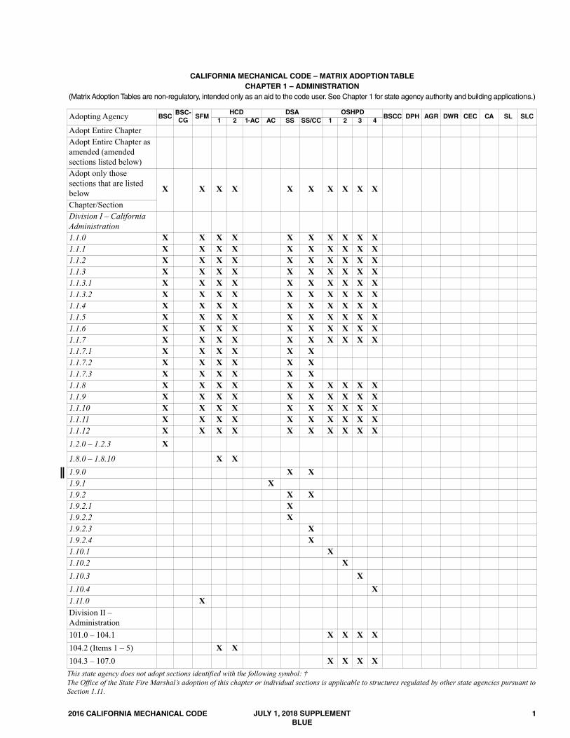
CALIFORNIA MECHANICAL CODE – MATRIX ADOPTION TABLECHAPTER 1 – ADMINISTRATION
(Matrix Adoption Tables are non-regulatory, intended only as an aid to the code user. See Chapter 1 for state agency authority and building applications.)
Adopting Agency BSCBSC-CG
SFMHCD DSA OSHPD
BSCC DPH AGR DWR CEC CA SL SLC1 2 1-AC AC SS SS/CC 1 2 3 4
Adopt Entire ChapterAdopt Entire Chapter asamended (amendedsections listed below)Adopt only thosesections that are listedbelow X X X X X X X X X X
Chapter/SectionDivision I – CaliforniaAdministration1.1.0 X X X X X X X X X X1.1.1 X X X X X X X X X X1.1.2 X X X X X X X X X X1.1.3 X X X X X X X X X X1.1.3.1 X X X X X X X X X X1.1.3.2 X X X X X X X X X X1.1.4 X X X X X X X X X X1.1.5 X X X X X X X X X X1.1.6 X X X X X X X X X X1.1.7 X X X X X X X X X X1.1.7.1 X X X X X X1.1.7.2 X X X X X X1.1.7.3 X X X X X X1.1.8 X X X X X X X X X X1.1.9 X X X X X X X X X X1.1.10 X X X X X X X X X X1.1.11 X X X X X X X X X X1.1.12 X X X X X X X X X X1.2.0 – 1.2.3 X
1.8.0 – 1.8.10 X X1.9.0 X X1.9.1 X1.9.2 X X1.9.2.1 X1.9.2.2 X1.9.2.3 X1.9.2.4 X1.10.1 X1.10.2 X1.10.3 X1.10.4 X1.11.0 XDivision II –Administration101.0 – 104.1 X X X X104.2 (Items 1 – 5) X X104.3 – 107.0 X X X XThis state agency does not adopt sections identified with the following symbol: †The Office of the State Fire Marshal’s adoption of this chapter or individual sections is applicable to structures regulated by other state agencies pursuant toSection 1.11.
JULY 1, 2018 SUPPLEMENTBLUE

2 2016 CALIFORNIA MECHANICAL CODE

272016 CALIFORNIA MECHANICAL CODE
CALIFORNIA MECHANICAL CODE – MATRIX ADOPTION TABLECHAPTER 2 – DEFINITIONS
(Matrix Adoption Tables are non-regulatory, intended only as an aid to the code user. See Chapter 1 for state agency authority and building applications.)
Adopting Agency BSCBSC-CG
SFMHCD DSA OSHPD
BSCC DPH AGR DWR CEC CA SL SLC1 2 1-AC AC SS SS/CC 1 2 3 4
Adopt Entire Chapter
Adopt Entire Chapter asamended (amendedsections listed below)
X X X X X X X X X X X
Adopt only thosesections that are listedbelowArticle/Section203.0 X X X X X X X204.0 X X X X X X X206.0 X X207.0 X X X X X X X208.0 X X X X209.0 X X X X X X X X X210.0 X X X X214.0 X X X215.0 X216.0 X X217.0 X X X X X X X218.0 X X222.0 X X223.0 X X X X X X XThis state agency does not adopt sections identified with the following symbol: †The Office of the State Fire Marshal’s adoption of this chapter or individual sections is applicable to structures regulated by other state agencies pursuant toSection 1.11.
JULY 1, 2018 SUPPLEMENTBLUE

28 2016 CALIFORNIA MECHANICAL CODE

452016 CALIFORNIA MECHANICAL CODE
CALIFORNIA MECHANICAL CODE – MATRIX ADOPTION TABLECHAPTER 3 – GENERAL REGULATIONS
(Matrix Adoption Tables are non-regulatory, intended only as an aid to the code user. See Chapter 1 for state agency authority and building applications.)
Adopting Agency BSCBSC-CG
SFMHCD DSA OSHPD
BSCC DPH AGR DWR CEC CA SL SLC1 2 1-AC AC SS SS/CC 1 2 3 4
Adopt Entire Chapter XAdopt Entire Chapter asamended (amended sectionslisted below)
X X X X X X X X X
Adopt only those sectionsthat are listed below
Chapter/Section303.2, Exception X X X X303.7 X X X303.7.1 X X318.0 X X X319.1 x X X319.2 X X320.1 X X320.2 X X320.3 X320.4 X X320.5 X X X321.0 X X X X322.0 X X X X322.1 X X X XThis state agency does not adopt sections identified with the following symbol: †The Office of the State Fire Marshal’s adoption of this chapter or individual sections is applicable to structures regulated by other state agencies pursuant toSection 1.11.
JULY 1, 2018 SUPPLEMENTBLUE

46 2016 CALIFORNIA MECHANICAL CODE
55
GENERAL REGULATIONS
2016 CALIFORNIA MECHANICAL CODE
316.7.2 Exterior Walls. In exterior walls, annular spacebetween sleeves and pipes or tubing shall be sealed andmade watertight, as approved by the Authority HavingJurisdiction. A penetration through fire-resistiveconstruction shall be in accordance with Section 316.5.
316.8 Firewalls. A pipe sleeve through a firewall shall havethe space around the pipe or tubing completely sealed withan approved fire-resistive material in accordance with othercodes.316.9 Structural Members. A structural member weakenedor impaired by cutting, notching, or otherwise shall be rein-forced, repaired, or replaced so as to be left in a safe structuralcondition in accordance with the requirements of the buildingcode.316.10 Rodentproofing. Mechanical system shall beconstructed in such a manner as to restrict rodents or verminfrom entering a building by following the ductwork from theoutside into the building.316.11 Metal Collars. In or on buildings where openingshave been made in walls, floors, or ceilings for the passage ofductwork or pipes, such openings shall be closed andprotected by the installation of approved metal collarssecurely fastened to the adjoining structure.
317.0 Trenching, Excavation, and Backfill.317.1 Trenches. Trenches deeper than the footings of abuilding or structure, and paralleling the same, shall belocated not less than 45 degrees (0.79 rad) from the bottomexterior edge of the footing, or as approved in accordancewith Section 302.0.317.2 Tunneling and Driving. Tunneling and driving shallbe permitted to be done in yards, courts, or driveways of abuilding site. Where sufficient depth is available to permit,tunnels shall be permitted to be used between open-cuttrenches. Tunnels shall have a clear height of 2 feet (610 mm)above the pipe and shall be limited in length to one-half thedepth of the trench, with a maximum length of 8 feet (2438mm). Where pipes are driven, the drive pipe shall be not lessthan one size larger than the pipe to be laid.317.3 Open Trenches. Excavations required to be made forthe installation of a mechanical system or part thereof, withinthe walls of a building, shall be open trench work and shall bekept open until it has been inspected, tested, and accepted.317.4 Excavations. Excavations shall be completely back-filled as soon after inspection as practicable. Precaution shallbe taken to ensure compactness of backfill around pipingwithout damage to such piping. Trenches shall be backfilledin thin layers to 12 inches (305 mm) above the top of thepiping with clean earth, which shall not contain stones, boul-ders, cinderfill, frozen earth, construction debris, or othermaterials that will damage or break the piping or causecorrosive action. Mechanical devices such as bulldozers,graders, etc., shall be permitted to then be used to completebackfill to grade. Fill shall be properly compacted. Precau-tions shall be taken to ensure permanent stability for pipe laidin filled or made ground.
318.0 Scope.318.1 Applicability. This part is applicable to health facili-ties regulated by OSHPD (See Adoption Tables for applica-tion for specific sections).Note: This section has no corresponding provisions in theUMC. For the scope and authority of each state agency, referto Chapter 1.318.2 Services/Systems and Utilities. Refer to Section1224.4.1 of the California Building Code.
319.0 Steam and Hot-Water Systems.319.1 Requirements for Hospitals and Optional ServicesProvided in Correctional Treatment Centers. [OSHPD 1 & 4]
319.1.1 Boilers shall have the capacity, based upon therest ratings published by the Hydronics Institute oranother acceptable national standard to supply thenormal operating requirements of all connected systemsand equipment.319.1.2 A minimum of two boilers shall be provided. Thearrangement of boilers shall be based on the capacityand capability of a boiler or boilers to operate allsystems during-periods of breakdown or maintenance ofany one boiler.319.1.3 Boiler systems providing space heating shall bedesigned to maintain a minimum temperature of 60°F(15.6°C) in general patient areas and the temperaturesspecified in Table 4-A for sensitive areas during periodsof breakdown or maintenance of any one boiler.319.1.4 Boiler feed pumps, condensate return pumps,fuel oil pumps, and heating circulating pumps shall beconnected and installed to provide standby service in theevent of pump failure. Installation of duplex pumps orprovision of a spare pump will meet this requirement.319.1.5 At least two sources of heat (e.g. two pieces ofequipment) shall be provided for supplying essentialservices such as sterilizers, hot water for dishwashing,and domestic hot water for minimum patient service,such as handwashing and baths. Booster heaters fordishwashing providing 125°F to 180°F (52°C to 82°C)water may be counted as the second source of heat forthat service.
319.2 Requirements for Skilled Nursing, Intermediate CareFacilities and Basic Services Provided in CorrectionalTreatment Centers. [For OSHPD 2 & 4]
319.2.1 Boilers, if provided, shall accommodate Section319.1.319.2.2 Two or more interconnected water heaters arean acceptable means to provide two sources of heat forhot water (See Section 319.1.5).
320.0 Air Conditioning and Heating Systems.320.1 Requirements for Hospitals and Optional ServicesProvided in Correctional Treatment Centers. [OSHPD 1 & 4]
320.1.1 The systems shall be designed to provide thetemperatures and relative humidity for sensitive areas orrooms shown in Table 4-A. When outdoor humidity and
»
»
»
»
»
»
»
»
JULY 1, 2018 SUPPLEMENTBLUE

56
GENERAL REGULATIONS
2016 CALIFORNIA MECHANICAL CODE
internal moisture sources are not sufficient to meet therequirements of sensitive areas or rooms in Table 4-A,humidification shall be provided by means of the health-care facility air-handling systems. Temperature shall beindividually controlled for each operating and deliveryroom. Burn unit patient rooms that require humidifiersto comply with the requirements of sensitive areas orrooms in Table 4-A shall be provided with individualhumidity control. All humidifiers shall use dry steam.Humidifiers shall be located within air handling systemsor ductwork to avoid moisture accumulation in down-stream components, including filters and insulation.320.1.2 Heating systems shall be designed based on the“Heating DB 99.6%” column of the Climatic DesignData in ASHRAE Handbook-Fundamentals. The systemsshall be thermostatically controlled with appropriatezoning to achieve the above conditions.320.1.3 Cooling systems shall be designed based on the0.4% columns of the four Annual Design Conditionstitled Cooling, Evaporation, Dehumidification, andEnthalpy shown by the Climate Design Data in ASHRAEHandbook-Fundamentals. The systems shall be thermo-statically controlled with appropriate zoning to achievethe above conditions.
320.2 Requirements for Skilled Nursing, Intermediate CareFacilities and Basic Services Provided in CorrectionalTreatment Centers. [For OSHPD 2 & 4]
320.2.1 Systems shall accommodate the provisions ofSections 320.1.2 through 320.1.3.320.2.2 Where air conditioning is provided, the systemshall be thermostatically controlled in one or more zones.
320.3 Requirements for Outpatient Facilities and LicensedClinics. [For OSHPD 3]
320.3.1 The system shall be designed to provide thetemperature and humidity’s for sensitive areas for roomsshown in Table 4-A.
320.4 Telephone and Data Equipment Rooms. [OSHPD 1 &4] Where telecommunications service entrance rooms, tech-nology equipment centers, or technology distribution roomsare provided in accordance with Section 1224.5 of the Cali-fornia Building Code, the following requirements shall apply:
320.4.1 Power for HVAC systems serving the room(s)shall be supplied by the Equipment Branch pursuant tothe California Electrical Code. Where redundant systemsare provided, only one shall be required to be supplied bythe Equipment Branch. 320.4.2 Mechanical equipment or fixtures that are notdirectly related to the support of the room shall not beinstalled in or pass through the room. Exception:Unrelated ductwork may be installed and shallbe not less than 10 feet (3048 mm) above the finished floor.320.4.3 HVAC systems shall be provided to maintainenvironmental conditions recommended in ASHRAE’sThermal Guidelines for Data Processing Environmentand the requirements of the specific equipment installed.
320.5 Psychiatric Services. [OSHPD 1, 2, & 4] For projectsassociated with provision of psychiatric services in acute
psychiatric hospitals, general acute-care hospitals, andspecial treatment program service units in skilled nursingfacilities, psychiatric, seclusion, and holding-patient roomsshall be designed with security diffusers, grilles, and registers.
321.0 Essential Mechanical Provisions. [OSHPD 1, 2, 3(Surgical Clinics only) & 4] During periods of poweroutages essential electrical power shall be provided for thefollowing equipment:321.1 (Does not apply to OSHPD 3 surgical clinic.) Allheating equipment necessary to maintain a minimum temper-ature of 60°F (15.6°) in patient areas which are not specifiedin Section 322.0.321.2 All heating equipment necessary to maintain theminimum temperatures listed in Table 4-A for sensitive areasspecified in Section 322.0.321.3 Equipment necessary for humidification of the areaslisted in Section 322.0.321.4 All supply, return, and exhaust fans required to maintainthe positive and negative air balances as required in Table 4-A.321.5 All control components and control systems necessaryfor the normal operation of equipment required to have essen-tial electrical power.321.6 Alarms for airborne infection isolation rooms andprotective environment rooms.
322.0 Sensitive Areas or Rooms. [OSHPD 1, 2, 3 (SurgicalClinics) & 4] The following are sensitive areas or rooms:(1) Operating room, hybrid operation room(2) Cystoscopy(3) Cardiac catheterization lab(4) Trauma/cardiac room (5) Delivery room, cesarean operating room(6) Gastrointestinal endoscopy procedure room(7) Post-anesthesia care unit(8) Newborn nursery(9) Newborn intensive-care nursery unit(10) Intensive care(11) Burn unit322.1 The following conditions shall be met for sensitiveareas or rooms:(1) Thermostats and humidistats shall be either locally reset-
table and of the non-locking type or remotely resettableand of the locking type.
(2) Systems shall be capable of maintaining the rooms withinthe temperature range in Table 4-A during normal oper-ation. Lower or higher temperature shall be permittedwhen patients’ comfort and/or medical conditions requirethose conditions.
(3) The humidity ranges listed in Table 4-A are the minimumand maximum limits where control is specifically needed.
(4) Types of intensive care service spaces are listed in theCalifornia Building Code.
JULY 1, 2018 SUPPLEMENTBLUE

612016 CALIFORNIA MECHANICAL CODE
CALIFORNIA MECHANICAL CODE – MATRIX ADOPTION TABLECHAPTER 4 – VENTILATION AIR
(Matrix Adoption Tables are non-regulatory, intended only as an aid to the code user. See Chapter 1 for state agency authority and building applications.)
Adopting Agency BSCBSC-CG
SFMHCD DSA OSHPD
BSCC DPH AGR DWR CEC CA SL SLC1 2 1-AC AC SS SS/CC 1 2 3 4
Adopt Entire Chapter
Adopt Entire Chapter asamended (amendedsections listed below)
X X X X X X
Adopt only thosesections that are listedbelow X X X X
Chapter/Section401.0 X X X X X402.0 X X X X402.1 X X X X X X X402.5 X X403.0 X X X X403.7.2.1 – 403.7.2.4 X X X405.0 X X X X407.0 X X X X408.0 X X X X409.0 X X X X410.0 X X X X411.0 X X X X412.0 X X X X413.0 X X X X414.0 X X X X415.0 X X X X416.0 X X X X416.3 X417.0 X X X X418.0 X X X XTable 4-A X X X XTable 4-B X XTable 4-C X XTable 402.1 X X XTable 403.7 Note 10 & 11 X XThis state agency does not adopt sections identified with the following symbol: †The Office of the State Fire Marshal’s adoption of this chapter or individual sections is applicable to structures regulated by other state agencies pursuant toSection 1.11.
JULY 1, 2018 SUPPLEMENTBLUE

62 2016 CALIFORNIA MECHANICAL CODE

401.0 General. 401.1 Applicability. This chapter contains requirements forventilation air supply, exhaust, and makeup air requirementsfor occupiable spaces within a building. [OSHPD 1, 2, 3 & 4]See Sections 404.0 through 418.0. [SFM] Air filters shallcomply with all requirements of Part 12, Title 24, Chapter 12-71, SFM Standard 12-71-1.
402.0 Ventilation Air. [Not permitted for OSHPD 1, 2, 3 & 4]402.1 Occupiable Spaces. Occupiable spaces listed in Table402.1 shall be designed to have ventilation (outdoor) air foroccupants in accordance with this chapter. Ventilation airsupply requirements for occupancies regulated by the Cali-fornia Energy Commission are found in the California EnergyCode.
402.1.1 Construction Documents. The outdoor airventilation rate and air distribution assumptions made inthe design of the ventilation system shall be clearly iden-tified on the construction documents.402.1.2 Dwelling. Requirements for ventilation air ratefor single-family dwellings shall be in accordance withthis chapter or ASHRAE 62.2.402.1.3 Ventilation in Health Care Facilities.Mechan-ical ventilation for health care facilities shall be designedand installed in accordance with this code and ASHRAE170-2013, through Addendum ae, as published with“Guidelines for Design and Construction of Hospitals andOutpatient Facilities,” 2014 edition (published by TheFacility Guidelines Institute). All supply-air, return air,and exhaust-air systems shall comply with ASHRAE 170.The text of ASHRAE 170 shall be modified as follows:(1) ASHRAE 170. Section 6.1.2.1 -- Not adopted.(2) ASHRAE 170. Section 6.3.2 -- Not adopted.(3) ASHRAE 170. Table 6.4 - Not adopted.(4) ASHRAE 170. Section 6.4-6.4.4 -- Not adopted.(5) ASHRAE 170. Section 6.9 -- Not adopted. (6) ASHRAE 170. Section 7.1a -- Modify as follows:
Replace reference to Table 7.1 with reference toTable 4-A.
(7) ASHRAE 170. Section 7.2.1a through e -- Notadopted.
(8) ASHRAE 170. Section 7.2.2 a through c, and e --Not adopted
(9) ASHRAE 170. Section 7.2.3 -- Not adopted.(10) ASHRAE 170. Section 7.3.1 -- Modify as follows:
Replace reference to Table 7.1 with reference toTable 4-A.
(11) ASHRAE 170. Section 7.4.1 -- Modify as follows:Delete the Exception that allows for high returngrilles.
402.2 Natural Ventilation.Natural ventilation systems shallbe designed in accordance with this section and shall includemechanical ventilation systems designed in accordance withSection 403.0, Section 404.0, or both. Exceptions:(1) An engineered natural ventilation system where
approved by the Authority Having Jurisdiction need notcomply with Section 402.2.
(2) A mechanical ventilation system is not required wherenatural ventilation openings comply with the require-ments of Section 402.2 and are permanently open or havecontrols that prevent the openings from being closedduring occupancy.
(3) A mechanical ventilation system is not required wherethe zone is not served by heating or cooling equipment.[ASHRAE 62.1:6.4]402.2.1 Floor Area to Be Ventilated. Spaces, or portionsof spaces, to be naturally ventilated shall be locatedwithin a distance based on the ceiling height, in accor-dance with Section 402.2.1.1, Section 402.2.1.2, orSection 402.2.1.3, from operable wall openings in accor-dance with Section 402.2.2. For spaces with ceilingswhich are not parallel to the floor, the ceiling height shallbe determined in accordance with Section 402.2.1.4.[ASHRAE 62.1:6.4.1]
402.2.1.1 Single Side Opening. For spaces withoperable openings on one side of the space, thedistance from the operable openings shall be notmore than 2H, where H is the ceiling height.[ASHRAE 62.1:6.4.1.1]402.2.1.2 Double Side Opening. For spaces withoperable openings on two opposite sides of thespace, the distance from the operable openings shallbe not more than 5H, where H is the ceiling height.[ASHRAE 62.1:6.4.1.2]402.2.1.3 Corner Openings. For spaces with oper-able openings on two adjacent sides of a space, suchas two sides of a corner, the distance from the oper-able openings shall be not more than 5H along a linedrawn between the two openings that are farthestapart. Floor area outside that line shall comply withSection 402.2.1.1. [ASHRAE 62.1:6.4.1.3]402.2.1.4 Ceiling Height. The ceiling height, H, tobe used in Section 402.2.1.1 through Section402.2.1.3 shall be the minimum ceiling height in thespace.Exception: For ceilings that are increasing in heightas distance from the openings is increased, theceiling height shall be determined as the averageheight of the ceiling within 20 feet (6096 mm) fromthe operable openings. [ASHRAE 62.1:6.4.1.4]
632016 CALIFORNIA MECHANICAL CODE
CHAPTER 4VENTILATION AIR
JULY 1, 2018 SUPPLEMENTBLUE

64
402.2.2 Location and Size of Openings. Spaces, orportions of spaces, to be naturally ventilated shall bepermanently open to operable wall openings directly tothe outdoors, the openable area of which is a minimum of4 percent of the net occupiable floor area. Where openingsare covered with louvers or otherwise obstructed, open-able area shall be based on the net free unobstructed areathrough the opening. Where interior rooms, or portions ofrooms, without direct openings to the outdoors are venti-lated through adjoining rooms, the opening between roomsshall be permanently unobstructed and shall have a freearea of not less than 8 percent of the area of the interiorroom nor less than 25 square feet (2.3 m2). [ASHRAE62.1:6.4.2]402.2.3 Control and Accessibility. The means to openrequired operable openings shall be readily accessible tobuilding occupants where the space is occupied. Controlsshall be designed to coordinate operation of the naturaland mechanical ventilation systems. [ASHRAE62.1:6.4.3]
402.3 Mechanical Ventilation.Where natural ventilation isnot permitted by this section or the building code, mechanicalventilation systems shall be designed, constructed, andinstalled to provide a method of supply air and exhaust air.Mechanical ventilation systems shall include controls, manualor automatic, that enable the fan system to operate whereverthe spaces served are occupied. The system shall be designedto maintain minimum outdoor airflow as required by Section403.0 under any load conditions.402.4 Outdoor Air Intake Protection. Required outdoor-airintakes shall be covered with a screen having not less than 1⁄4of an inch (6.4 mm) openings, and shall have not more than 1⁄2of an inch (12.7 mm) openings.
402.4.1 Weather Protections. Outdoor air intakes thatare part of the mechanical ventilation system shall bedesigned to manage rain entrainment, to prevent rainintrusion, and manage water from snow in accordancewith ASHRAE 62.1.
402.5 Bathroom Exhaust Fans. [HCD 1 & HCD 2] Eachbathroom shall be mechanically ventilated in accordance withDivision 4.5 of the California Green Building Standards Code(CALGreen).
403.0 Ventilation Rates. [Not permitted for OSHPD 1, 2, 3& 4]403.1 General. The design outdoor air intake flow rate for aventilation system shall be determined in accordance withSection 403.2 through Section 403.9.4.403.2 Zone Calculations. Ventilation zone parameters shallbe determined in accordance with Section 403.2.1 throughSection 403.2.3 for each ventilation zone served by the venti-lation system. [ASHRAE 62.1:6.2.2]
403.2.1 Breathing Zone Outdoor Airflow. The outdoorairflow required in the breathing zone of the occupiablespace or spaces in a ventilation zone, i.e., the breathing
zone outdoor airflow (Vbz), shall be not less than thevalue determined in accordance with Equation 403.2.1.
Vbz = Rp•Pz + Ra•Az (Equation 403.2.1)
Where:Az = zone floor area: the net occupiable floor area of
the ventilation zone, square feet (m2).Pz = zone population: The number of people in the venti-
lation zone during typical usage. Rp= outdoor airflow rate required per person as deter-
mined from Table 402.1.Ra= outdoor airflow rate required per unit area as deter-
mined from Table 402.1. [ASHRAE 62.1:6.2.2.1]403.2.2 Zone Air Distribution Effectiveness. The zoneair distribution effectiveness (Ez ) shall be not greaterthan the default value determined in accordance withTable 403.2.2. [ASHRAE 62.1:6.2.2.2]403.2.3 Zone Outdoor Airflow. The zone outdoorairflow (Voz), i.e., the outdoor airflow rate that shall beprovided to the ventilation zone by the supply air distri-bution system, shall be determined in accordance withEquation 403.2.3. [ASHRAE 62.1:6.2.2.3]
Voz = Vbz / Ez (Equation 403.2.3)
403.3 Single-Zone Systems. For ventilation systems whereone or more air handlers supply a mixture of outdoor air andrecirculated air to only one ventilation zone, the outdoor airintake flow (Vot) shall be determined in accordance withEquation 403.3. [ASHRAE 62.1:6.2.3]
Vot = Voz (Equation 403.3)
403.4 One Hundred Percent Outdoor Air Systems. Forventilation systems where one or more air handlers supplyonly outdoor air to one or more ventilation zones, the outdoorair intake flow (Vot ) shall be determined in accordance withEquation 403.4. [ASHRAE 62.1:6.2.4]
Vot = ∑ all zones Voz (Equation 403.4)
403.5 Multiple-Zone Recirculating Systems. For ventila-tion systems where one or more air handlers supply a mixtureof outdoor air and recirculated air to more than one ventila-tion zone, the outdoor air intake flow (Vot) shall be deter-mined in accordance with Section 403.5.1 through Section403.5.4. [ASHRAE 62.1:6.2.5]
403.5.1 Primary Outdoor Air Fraction. The primaryoutdoor air fraction (Zpz ) shall be determined for venti-lation zones in accordance with Equation 403.5.1.[ASHRAE 62.1:6.2.5.1]
2016 CALIFORNIA MECHANICAL CODE
VENTILATION AIR
»
»
JULY 1, 2018 SUPPLEMENTBLUE

65
Zpz = Voz /Vpz (Equation 403.5.1)
Where:Vpz is the zone primary airflow, i.e., the primary airflowrate to the ventilation zone from the air handler, includingoutdoor air and recirculated air. [ASHRAE 62.1:6.2.5.1]403.5.2 System Ventilation Efficiency. The systemventilation efficiency (Ev) shall be determined in accor-dance with Table 403.5.2 or Section 404.0. [ASHRAE62.1:6.2.5.2]403.5.3 Uncorrected Outdoor Air Intake. The uncor-rected outdoor air intake (Vou) flow shall be determined inaccordance with Equation 403.5.3(1). [ASHRAE62.1:6.2.5.3]
[Equation 403.5.3(1)]Vou = D ∑ all zones (Rp•Pz) + ∑ all zones (Ra•Az)
The occupant diversity ratio (D) shall be determinedin accordance with Equation 403.5.3(2) to account forvariations in population within the ventilation zones servedby the system.
D = Ps / ∑ all zones Pz [Equation 403.5.3(2)]
Where the system population (Ps) is the total popu-lation in the area served by the system. Exception:Alternative methods to account for occupantdiversity shall be permitted, provided that the resulting(Vou) value is not less than that determined in accordancewith Equation 403.5.3(1). [ASHRAE 62.1:6.2.5.3.1]403.5.4 Outdoor Air Intake. The design outdoor airintake flow (Vot) shall be determined in accordance withEquation 403.5.4. [ASHRAE 62.1:6.2.5.4]
Vot = Vou/Ev (Equation 403.5.4)
403.6 Design for Varying Operating Conditions. Ventila-tion systems shall be designed to be capable of providing notless than the minimum ventilation rates required in thebreathing zone where the zones served by the system are occu-pied, including all full and part-load conditions. The minimumoutdoor air intake flow shall be permitted to be less than thedesign value at part-load conditions. [ASHRAE 62.1:6.2.6.1]
403.6.1 Short-Term Conditions.Where it is known thatpeak occupancy will be of short duration or the ventila-tion will be varied or interrupted for a short period oftime, the design shall be permitted to be based on theaverage conditions over a time period (T) determined inaccordance with Equation 403.6.1.
T = 3v/Vbz (Equation 403.6.1)
Where:T = averaging time period, minutes.v = the volume of the ventilation zone for which
averaging is being applied, cubic foot (m3).Vbz = the breathing zone outdoor airflow determined
in accordance with Equation 403.2.1 and designvalue of the zone population (Pz), cubic foot perminute (cfm) (m3/min).
Acceptable design adjustments based on this optionalprovision shall be in accordance with the following:(1) Zones with fluctuating occupancy: The zone popu-
lation (Pz) shall be permitted to be averaged overtime (T).
(2) Zones with intermittent interruption of supply air: Theaverage outdoor airflow supplied to the breathingzone over time (T) shall be not less than the breathingzone outdoor airflow (Vbz) calculated using Equation403.2.1.
(3) Systems with intermittent closure of the outdoor airintake: The average outdoor air intake over time (T)shall be not less than the minimum outdoor air intake(Vot) calculated using Equation 403.3, Equation 403.4,or Equation 403.5.4. [ASHRAE 62.1:6.2.6.2]
403.7 Exhaust Ventilation. Exhaust airflow shall beprovided in accordance with the requirements in Table 403.7.Exhaust makeup air shall be permitted to be a combinationof outdoor air, recirculated air, and transfer air.
403.7.1 Parking Garages. Exhaust rate for parkinggarages shall be in accordance with Table 403.7. Exhaustrate shall not be required for enclosed parking garageshaving a floor area of 1000 square feet (92.9 m2) or lessand used for the storage of 5 or less vehicles.403.7.2 Enclosed Parking Garages. Mechanical venti-lation systems for enclosed parking garages shall operatecontinuously.Exceptions:(1) Mechanical ventilation systems shall be permitted
to operate intermittently where the system isdesigned to operate automatically upon detection ofvehicle operation or the presence of occupants byapproved automatic detection devices.
(2) Approved automatic carbon monoxide sensingdevices shall be permitted to be employed to modu-late the ventilation system to not exceed a maximumaverage concentration of carbon monoxide of 50parts per million during an eight-hour period, with aconcentration of not more than 200 parts per millionfor a period not exceeding one hour. Automaticcarbon monoxide sensing devices installed to modu-lated parking garage ventilation systems shall beapproved in accordance with Section 301.2.403.7.2.1 Alternative Exhaust Ventilation forEnclosed Parking Garages. 403.7.2.2 Minimum Exhaust Rate. [HCD 1 & 2] Inlieu of the exhaust rates in Table 403.7, ventilationsystems shall be capable of providing 14,000 cfm
2016 CALIFORNIA MECHANICAL CODE
VENTILATION AIR
JULY 1, 2018 SUPPLEMENTBLUE
(6608 L/s) of exhaust air for each operating vehicle.Number of operating vehicles shall be determinedbased on 2.5 percent of all parking spaces (and notless than one vehicle).403.7.2.3 Exhaust Inlet Distribution. [HCD 1 & 2]To ensure proper exhaust of contaminated air andfumes from parking garages, exhaust systemsutilizing multiple exhaust inlets shall be designed sothat exhaust inlets are distributed in such a mannerthat no portion of the parking garage is more than50 feet (15 240 mm) from an exhaust inlet. Suchexhaust inlets shall be installed so that the highestelevation of the exhaust inlet is no greater than 12inches (305 mm) below the lowest ceiling level.Exception:Garage exhaust systems designed withoutdistributed exhaust inlets may have their exhaustinlets designed based on the principles of engineeringand mechanics and shall provide the minimumrequired exhaust rate in Table 403.7.403.7.2.4 Exhaust System Operation. [HCD 1 & 2]Exhaust systems shall operate continuously unlessone of the exceptions to continuous operation ofSection 403.7 is utilized.
403.8 Dynamic Reset. The system shall be permitted to bedesigned to reset the outdoor air intake flow (Vot), the spaceor ventilation zone airflow (Voz ) as operating conditionschange. [ASHRAE 62.1:6.2.7]403.9 Air Classification and Recirculation. Air shall beclassified, and the recirculation or transfer shall be limited inaccordance with Section 403.9.1 through Section 403.9.4.[ASHRAE 62.1:5.16] Recirculated air shall not be taken fromprohibited locations in accordance with Section 311.3.
403.9.1 Class 1 Air. Recirculation or transfer of Class 1air to other spaces shall be permitted. [ASHRAE62.1:5.16.3.1]403.9.2 Class 2 Air. Recirculation of Class 2 air withinthe space of origin shall be permitted. Recirculation ortransfer of Class 2 air to other Class 2 or Class 3 spacesshall be permitted, provided the other spaces are used forthe same or similar purpose or task and involve the sameor similar pollutant sources as the Class 2 space. Transferof Class 2 air to toilet rooms shall be permitted. Recir-culation or transfer of Class 2 air to Class 4 spaces shallbe permitted. Class 2 air shall not be recirculated or trans-ferred to Class 1 spaces. Where using an energy recoverdevice, recirculation from leakage, carryover, or transferfrom the exhaust side of the energy recovery device shallbe permitted and the recirculated Class 2 air shall notexceed 10 percent of the outdoor air intake flow.[ASHRAE 62.1:5.16.3.2]403.9.3 Class 3 Air. Recirculation of Class 3 air withinthe space of origin shall be permitted. Class 3 air shallnot be recirculated or transferred to other spaces. Whereusing an energy recover device, recirculation fromleakage, carryover, or transfer from the exhaust side ofthe energy recovery device shall be permitted and therecirculated Class 3 air shall not exceed 5 percent of theoutdoor air intake flow. [ASHRAE 62.1:5.16.3.3]
403.9.4 Class 4 Air. Class 4 air shall not be recirculatedor transferred to other spaces or be recirculated withinthe space of origin. [ASHRAE 62.1:5.16.3.4]
404.0 Multiple-Zone Systems.404.1 General.This section presents an alternative procedurefor calculating the system ventilation efficiency (Ev) wherevalues in Table 403.5.2 are not used. The system ventilationefficiency shall equal the lowest zone ventilation efficiencyamong the ventilation zones served by the air handler inaccordance with Equation 404.1. [ASHRAE 62.1:A1.3]
Ev = minimum (Evz) (Equation 404.1)
404.2 Average Outdoor Air Fraction. The average outdoorair fraction (Xs) for the ventilation system shall be determinedin accordance with Equation 404.2.
Xs =Vou/Vps (Equation 404.2)
The uncorrected outdoor air intake (Vou) shall be deter-mined in accordance with Section 403.5.3, and the systemprimary airflow (Vps) shall be determined at the conditionanalyzed. [ASHRAE 62.1:A1.1]404.3 Zone Ventilation Efficiency. The zone ventilation effi-ciency (Evz) shall be the efficiency with which a systemdistributes outdoor air from the intake to an individualbreathing zone, and shall be determined in accordance withSection 404.3.1 or Section 404.3.2. [ASHRAE 62.1:A1.2]
404.3.1 Single Supply Systems. For single supplysystems, where the air supplied to a ventilation zone is amixture of outdoor air and system-level recirculated air,zone ventilation efficiency (Evz) shall be determined inaccordance with Equation 404.3.1. Examples of singlesupply systems include constant-volume reheat, single-duct VAV, single-fan dual-duct, and multizone systems.
Evz = 1+Xs–Zpz (Equation 404.3.1)
The average outdoor air fraction for the system (Xs)shall be determined in accordance with Equation 404.2and the primary outdoor air fraction for the zone (Zpz)shall be determined in accordance with Section 403.5.1.[ASHRAE 62.1:A1.2.1]404.3.2 Secondary-Recirculation Systems. Forsecondary-recirculation systems where the supply air or aportion thereof to a ventilation zone is recirculated airfrom other zones, without being directly mixed withoutdoor air, the zone ventilation efficiency (Evz) shall bedetermined in accordance with Equation 404.3.2(1).Examples of secondary-recirculation systems includedual-fan dual-duct and fan-powered mixing box systems,and systems that include transfer fans for conferencerooms.
66 2016 CALIFORNIA MECHANICAL CODE
VENTILATION AIR
«
«
«
JULY 1, 2018 SUPPLEMENTBLUE

67
[Equation 404.3.2(1)]Evz = (Fa+Xs•Fb–Zpz•Ep•Fc)/Fa
The system air fractions Fa, Fb, and Fc shall bedetermined in accordance with Equation 404.3.2(2),Equation 404.3.2(3), and Equation 404.3.2(4). The zoneprimary air fraction (Ep) shall be determined in accor-dance with Equation 404.3.2(5). For single-zone andsingle-supply systems Ep shall equal to 1.0. The zonesecondary recirculation fraction (Er) shall be determinedby the designer based on system configuration. The zoneair distribution effectiveness (Ez) shall be determined inaccordance with Section 403.2.2. [ASHRAE 62.1:A1.2.2]
Fa = Ep+(1–Ep)•Er [Equation 404.3.2(2)]
Fb = Ep [Equation 404.3.2(3)]
Fc = 1–(1–Ez)•(1–Er)•(1–Ep) [Equation 404.3.2(4)]
Ep = Vpz/Vdz [Equation 404.3.2(5)]
Where:Ep - Primary air fraction: The fraction of primary air inthe discharge air to the ventilation zone.Er - Secondary recirculation fraction: In systems withsecondary recirculation of return air, the fraction ofsecondary recirculated air to the zone that is representa-tive of average system return air rather than air directlyrecirculated from the zone.Fa - Supply air fraction: The fraction of supply air to theventilation zone from sources or air outside the zone.Fb - Mixed air fraction: The fraction of supply air to theventilation zone from fully mixed primary air.Fc - Outdoor air fraction: The fraction of outdoor air tothe ventilation zone from sources of air outside the zone.Vdz - Zone discharge airflow: The expected discharge(supply) airflow to the zone that includes primary airflowand secondary recirculated airflow, cfm (m3/min).Vpz - Zone primary airflow: Determine in accordancewith Section 403.5.1.Xs - Average outdoor air fraction: At the primary airhandler, the fraction of outdoor air intake flow in thesystem primary airflow.Zpz - Primary outdoor air fraction: The outdoor air frac-tion required in the primary air supplied to the ventilationzone prior to the introduction of secondary recirculationair. [ASHRAE 62.1: A4]
405.0 Evaporative Cooling System for Health Care Facilities.[For OSHPD 1, 2, 3 & 4] Direct evaporative cooling systemswhere the air directly contacts the wetted surface or spray shallbe limited in health facilities to nonpatient areas such aslaundry rooms, food preparation areas, and boiler ormachinery rooms. Similar rooms with high heating-producing
equipment will be considered when specifically approved bythe enforcing agency. The evaporative pads shall be a synthetictype. Filters shall be required in accordance with Tables 4-Band 4-C except utility rooms, i.e.: boiler or machinery rooms.
406.0 Reserved.
407.0 Ventilation System Details. [OSHPD 1, 2, 3 & 4]407.1 General.
407.1.1 All supply-air, return air, and exhaust-air systemsshall be mechanically operated and such systems forareas listed in Table 4-A shall be operated continuously.Natural ventilation through windows or other openingssuch as louvers will be considered as supplemental to therequired mechanical ventilation systems.Exceptions:(1) Natural ventilation shall not be used in airborne
infection isolation rooms and protective environmentrooms.
(2) The number of air changes may be reduced to 25percent of the indicated value in Table 4-A, when theroom is unoccupied, if provisions are made to ensurethe following:(1) The number of air changes per hour indicated
is reestablished whenever the space is occupied.(2) The pressure relationship with the surrounding
rooms is maintained when the air changes perhour are reduced. In areas requiring no contin-uous directional control as identified in accor-dance with Table 4-A, ventilation systems maybe shut down when the space is unoccupied andventilation is not otherwise required. Ventila-tion shall not be reduced in rooms specificallyused for airborne infection control, such aswaiting rooms, triage rooms, corridors, recep-tion areas, areas adjacent to waiting areas,airborne infection isolation rooms, negativepressure exam room, negative pressure x-raytreatment rooms, and protective environmentrooms. All operating and delivery rooms shallmaintain a minimum of six air changes per hourof total air when not in use.
407.1.2 Fans serving exhaust systems shall be located atthe discharge end of the system. The ventilation ratesshown in Table 4-A shall be considered as minimumacceptable rates and shall not be construed asprecluding the use of higher ventilation rates if they arerequired to meet design conditions.407.1.3 Services/Systems and Utilities. (Refer to Section1224.4.1 of the California Building Code).
407.2 Outdoor Air Intakes and Exhaust Outlets.407.2.1 Outdoor Air Intakes.Outdoor air intakes shall belocated at least 25 feet (7.62 m) from exhaust outlets ofventilating systems, combustion equipment stacks,medical-surgical vacuum systems, cooling towers, andareas that may collect vehicular exhaust or other noxious
2016 CALIFORNIA MECHANICAL CODE
VENTILATION AIR
JULY 1, 2018 SUPPLEMENTBLUE
68 2016 CALIFORNIA MECHANICAL CODE
VENTILATION AIR
fumes. Plumbing vents shall be located in relation tooutdoor air intakes per California Plumbing Code. Thebottom of outdoor air intakes shall be located as high aspracticable, but not less than 10 feet (3048 mm) aboveground level. If installed above the roof, they shall belocated 18 inches (457 mm) above roof level or 3 feet (914mm) above a flat roof where heavy snowfall is anticipated.Exceptions:(1) These dimensions may be reduced if it is demon-
strated by the submission of details and calculationsthat location of intakes with respect to exhausts andtheir orientation, or the use of special filters,provides equal performance.
(2) The requirements regarding the bottom of outdoorair intakes and installation through the roof do notapply to skilled nursing facilities, intermediate-carefacilities or nonsensitive areas in correctional treat-ment centers.
407.2.2 Exhaust Outlets. Exhaust outlets shall belocated a minimum of 10 feet (3048 mm) above adjoininggrade and 10 feet (3048 mm) from doors, occupied areas,and operable windows.Exception: Airborne infection isolation rooms shallcomply with Section 414.1.
407.3 Air Balance.407.3.1 The ventilation systems shall be designed andbalanced to provide the general air balance relationshipto adjacent areas, shown in Table 4-A. The ventilationsystems shall be balanced in accordance with the latestedition of standards published by the Associated AirBalance Council (AABC), the National EnvironmentalBalancing Bureau (NEBB), or the Testing, Adjusting andBalancing Bureau (TABB).
407.4 Air Circulation.407.4.1Design of the ventilation system shall provide airmovement that is generally from clean to less cleanareas.
407.4.1.1 Air supplied to operating rooms, cesareanoperating rooms, cardiac catheterization labs,cystoscopy rooms, delivery rooms, and nurseriesshall be delivered at or near the ceiling of the areaserved. In these areas and in morgues and autopsyrooms all air removed from the area shall beremoved near floor level. Exhaust or recirculationinlets shall be located not less than 3 inches (76 mm)nor more than 8 inches (203 mm) above the finishedfloor, except in morgues and autopsy rooms whereall of the exhaust air is removed through an autopsytable designed for this purpose. At least two exhaustor recirculation air inlets of equal capacity shall beused in all cardiac catheterization labs, cystoscopyrooms, operating rooms, and delivery rooms andshall be located not less than 3 inches (76 mm) normore than 8 inches (203 mm) above the finishedfloor.
Exception: For airborne infection isolation roomsand protective environment rooms, see Sections414.0 and 415.0.407.4.1.2 Room supply air outlets and room recir-culation and exhaust air inlets installed in nonsen-sitive areas shall be located not less than 3 inches(76 mm) above the floor.Exception: For airborne infection isolation roomsand protective environment rooms, see Sections414.0 and 415.0.407.4.1.3 Corridors shall not be used to conveysupply, return, or exhaust air to or from any room ifthe corridor is required to be of fire resistiveconstruction per the California Building Code.Exceptions: (1) Mechanically exhausted toilet rooms of 50
square feet (4.7 m2) or less and small rooms of30 square feet (2.79 m2) or less such as janitorclosets, housekeeping rooms, and electrical ortelephone closets opening directly ontocorridor.
(2) Air transfer caused by pressure differentials inrooms required to have a positive or negativeair balance by Table 4-A.
407.4.1.4 No space above a ceiling may be utilizedas an outside-air, relief-air, supply-air, exhaust-air,or return-air plenum.Exception: Designs specifically approved by theenforcing agency.407.4.1.5 Air from a patient room, exam room, treat-ment room shall not be transferred to anothersimilar room without first having passed through airfilters as required by Table 4-B or Table 4-C.407.4.1.6 Supply outlets and return and exhaust airinlets shall be located to prevent short-circuiting.
407.5 Variable Air Volume.407.5.1 Variable Air Volume Systems (VAV). Variableair volume systems subjecting the patient to a fluctuatingair movement are not acceptable for airborne infectionisolation rooms, protective environment rooms or thosecritically sensitive areas listed in Table 320.0. Fornonsensitive areas, variable air volume systems meetingthe following criteria can be considered:
407.5.1.1 The VAV system shall comply with coderequirements for outside air, total air, and pressurerelationship through the full range of operation fromminimum to maximum.407.5.1.2 The central return or exhaust fan shall becontrolled to accomplish the variable air volumerequirements of the individual rooms served by thefan as described in Section 407.5.1.3.407.5.1.3 Variable air volume for return or exhaustair shall be accomplished by utilizing an automatic
>
>
JULY 1, 2018 SUPPLEMENTBLUE
692016 CALIFORNIA MECHANICAL CODE
VENTILATION AIR
modulating damper in the return or exhaust air foreach zone. The damper will modulate from full opento minimum position in conjunction with the supplyair VAV terminal box.
408.0 Filters. [OSHPD 1, 2, 3 & 4]408.1 General. Filter efficiencies shall be certified by themanufacturer and shall be based on ASHRAE 52.2 Methodof Testing General Ventilation Air-Cleaning Devices forRemoval Efficiency by Particle Size when specifically setforth in these standards.
408.1.1 A filter gauge shall be installed across each filterbank serving central air systems. The gauge shall be redlined or a filter alarm light installed to signal when therecommended maximum static pressure drop has beenreached.408.1.2 Central air-handling systems are defined as anyunit requiring duct work on the supply or inlet side thatserve more than one room.408.1.3 Filter banks shall be visually inspected for tornmedia and bypass in filter frames by means of a flash-light or equivalent, both with fans in operation andstopped. Tears in media and bypass in filter frames shallbe eliminated in accordance with the manufacturer’sdirections and the requirements of the enforcing agencyprior to commencing operation of the system.408.1.4 Central air-handling systems shall be maintainedin a reasonably clean condition during construction andshall be cleaned as necessary prior to replacement oftemporary filter used during construction to ensure thatclean air will be delivered to the occupied spaces.408.1.5 Filter bank No. 1 shall be located upstream ofthe air-conditioning equipment. Filter bank No. 2 andfilter bank No. 3 shall be located downstream of thesupply fan and all cooling and humidification equipmentwith efficiencies as indicated in Table 4-B or Table 4-C.Exception: Dry steam-type humidifiers for local roomhumidity control may be installed in the supply air ductdownstream of the final filter bank where designs arespecifically approved by the enforcing agency. Dry steamis that which is defined in the ASHRAE HVAC Systemsand Equipment Handbook.408.1.6 Filter bank No. 2 and filter bank No. 3 mediashall be rigid or supported (noncollapsing type) andshall operate on the principles of impingement, straining,and diffusion.
408.2 Filters for Hospitals.408.2.1 All air-ventilation systems shall comply withcode requirements of this section and shall have filterbank efficiencies as listed in Table 4-B.408.2.2 Noncentral recirculating air systems providingcooling to high heat producing equipment located innonsensitive areas shall have a filter with 30 percentaverage efficiency based on ASHRAE 52.2 or a minimumefficiency reporting value (MERV) of 8 based onASHRAE 52.2.
408.2.3 Noncentral air systems serving any areas notlisted in Table 4-B shall be provided with filter arrange-ment and efficiency specifically approved by theenforcing agency.408.2.4 Noncentral recirculating air handling systems,for example, through-the-wall units, fan coil units, andheat pumps may be utilized for single patient rooms ofone or more beds. Filtration for these units shall have aminimum weight arrestance value of 50 percent, basedon ASHRAE 52.2 or a minimum efficiency reportingvalue (MERV) of 1, based on ASHRAE 52.2. The airventilation system providing the minimum air changes ofoutdoor air shall comply with Table 4-B. These units maybe used as recirculating units only. All outdoor airrequirements shall be met by a separate central airhandling systems.
408.3 Filters for Skilled Nursing Facilities, IntermediateCare Facilities, and Correctional Treatment Centers.
408.3.1 The air ventilation systems shall comply withcode requirements of this section for skilled nursing facil-ities, intermediate care facilities and correctional treat-ment centers and shall have filter bank efficiencies aslisted in Table 4-C.408.3.2 Noncentral air systems serving single patientrooms of one or more beds shall comply with Table 4-C.408.3.3 Noncentral recirculating air-handling systems,i.e. through the wall units, may be utilized for eachpatient room with one or more beds. Filtration for theseunits shall have a minimum weight arrestance value of 50percent, based on ASHRAE 52.2 or a minimum efficiencyreporting value (MERV) of 1, based on ASHRAE 52.2.The air ventilation system providing the minimum airchanges of outdoor air shall comply with Table 4-C.These units may be used as recirculating units only. Alloutdoor air requirements shall be met by a separatecentral air handling system.408.3.4 Airborne infection isolation rooms, protectiveenvironment rooms, and sensitive areas in correctionaltreatment centers shall comply with Section 408.2.
408.4 Filters for Outpatient Facilities.408.4.1 The air ventilation systems shall comply withcode requirements of this section for outpatient facilitiesand shall have filter bank efficiencies as listed in Table4-B.408.4.2 Noncentral air systems serving individual roomsshall comply with Table 4-B.
409.0 Ducts. [OSHPD 1, 2, 3 & 4]409.1Ducts which penetrate construction, intended for X-rayor other radiation protection, shall not impair the effective-ness of the protection.409.2 Duct linings and their use shall meet the requirementsof Chapter 6, California Mechanical Code.409.3 Insulation of Ducts. Cold air ducts shall be insulatedwherever necessary or to prevent condensation.
JULY 1, 2018 SUPPLEMENTBLUE
70 2016 CALIFORNIA MECHANICAL CODE
VENTILATION AIR
409.4 The anchorage and supporting structural elements forairducts shall be designed to withstand the lateral forces asrequired by the California Building Code, Title 24, Part 2.
410.0 Laboratory Ventilating Systems and Hoods. [OSHPD1, 2, 3 & 4]410.1 Laboratory Ventilating Systems. Laboratory venti-lating systems shall comply with NFPA 99, as required bySection 1224.4.6.4 of the California Building Code.410.2 Exhaust Hoods and Safety Cabinets. Hoods and safetycabinets may be used for normal exhaust of a space providedminimum air change rates are maintained. If air change stan-dards in Table 4-A do not provide sufficient air for properoperation of exhaust hoods and safety cabinets (when in use),supplementary makeup air (filtered and preheated) shall beprovided around these units to maintain the required airflowdirection and exhaust velocity. Makeup systems for hoods shallbe arranged to minimize “short circuiting” of air and to avoidreduction in air velocity at the point of contaminant capture.410.3 Laboratory Fume Hoods. Laboratory fume hoods shallmeet the following standards:
410.3.1 General Standard. Average face velocity shallbe at least 75 feet per minute (0.38 meters per second).Exhaust system shall be separate from the buildingexhaust system. Exhaust fan shall be located at thedischarge end of the system. Exhaust duct system shall beof noncombustible corrosion-resistant material asrequired to meet the planned usage of the hood.410.3.2 Special Standards for Use with Strong Oxidants.Fume hoods and their associated equipment in the airstream intended for use with perchloric acid and otherstrong oxidants shall be constructed of stainless steel orother material consistent with special exposures. Hoodsand equipment shall be provided with a water wash anddrain system to permit periodic flushing of duct and hood.When perchloric acid or other strong oxidants are onlytransferred from one container to another, standard labo-ratory fume hoods and the associated equipment may beused in lieu of stainless steel construction.410.3.3 Special Standards for Use with Infectious orRadioactive Materials. Each hood shall have a minimumface velocity of 90 to 110 feet per minute (0.45 to 0.56meters per second) with suitable pressure-independentair-modulating devices and alarms to alert staff of fanshutdown or loss of airflow. Each hood shall have filterswith a 99.97 percent efficiency (based on the DOP testmethod) in the exhaust stream and be designed andequipped to permit the safe removal, disposal, andreplacement of contaminated filters. Filters shall be asclose to the hood as practical to minimize duct contam-ination. Fume hoods intended for use with radioactiveisotopes shall be constructed of stainless steel or othermaterial suitable for the particular exposure.
411.0 Kitchen and Dining Areas. [OSHPD 1, 2, 3 & 4]411.1 The air from dining areas may be used to ventilate thefood preparation areas only after it has passed through a
filter with at least an 80 percent average efficiency based onASHRAE 52.2 or a minimum efficiency reporting value(MERV) of 13, based on ASHRAE 52.2.Exception: For skilled nursing facilities, intermediate carefacilities and correctional treatment centers, the air from diningarea may be used to ventilate food preparation areas only afterit has passed through a filter with a 50 percent average effi-ciency based on ASHRAE 52.2 or a minimum efficiencyreporting value (MERV) of 10, based on ASHRAE 52.2.
412.0 Boiler, Mechanical, and Electrical Rooms. [OSHPD1, 2, 3 & 4]412.1 Boiler, heater and electrical equipment rooms shall beprovided with outdoor air so as to maintain combustion ratesof equipment and temperatures in the rooms and in adjoiningareas as rated in this chapter.412.2 Floor surfaces in occupied spaces above such roomsshould not exceed a temperature of 85°F (29.4°C), and suit-able insulation may be required.
413.0 Odorous Rooms. [OSHPD 1, 2, 3 & 4] 413.1 Rooms in areas where excessive heat or moisture isgenerated, where objectional odors or dust are present, orwhere flammable or toxic gases may accumulate, which areused by health facility personnel or patients, shall be providedwith exhaust ventilation to change the air a minimum of tentimes per hour.413.2 Kitchen, morgues and laundries located inside ahospital building or skilled nursing facility in which patientsare accommodated, or treated, shall be ventilated withexhaust systems which will provide a minimum of ten airchanges per hour and prevent odors from entering patientareas.
414.0 Airborne Infection Isolations Rooms. [OSHPD 1, 2, 3& 4]414.1 Exhaust Systems. A separate, dedicated exhaustsystem shall be provided for airborne infection isolationrooms. The dedicated system may serve more than oneairborne infection isolation room, adjoining toilet room andanteroom. The exhaust ducts shall be identified by appro-priate labeling with the words "Caution Airborne InfectionIsolation Rooms Exhaust" or similar terminology. Suchlabeling shall be in a manner which is not readily removableand shall appear on the exhaust duct at intervals of not morethan 20 feet (6096 mm) and at least once near each roomand each story traversed by the exhaust system. Exhaust fansshall comply with Section 407.1.2. The discharge fromexhaust fans shall be located above the roof and shall belocated a minimum of 25 feet (7620 mm) from areas that maybe occupied, doors, operable windows, outdoor air intakes,or other openings into the building. The exhaust fandischarge shall be labeled in a manner which readily iden-tifies the precautions which should be observed. To ensurethat the airborne contaminates do not reenter the building,one of the following shall be provided:
JULY 1, 2018 SUPPLEMENTBLUE
712016 CALIFORNIA MECHANICAL CODE
VENTILATION AIR
414.1.1 Exhaust discharge from fan shall extend at least7 feet (2134 mm) above the roof and discharge verticallyupward. Self-draining stacks or equivalent shall be usedfor rain protection. Rain caps which divert the exhausttoward the roof shall be prohibited.414.1.2 Exhaust shall discharge above roof level andthrough an accessible HEPA filter. The HEPA filter shallbe located upstream of the exhaust fan and have aminimum efficiency of 99.97 percent based on the DOPmethod in accordance with Mil-Std. 282 or a minimumefficiency reporting value (MERV) of 17, based onASHRAE 52.2. Filter gage shall be installed across thefilter. For maintenance of air balance relationship, seeSection 407.3.2. The 25-foot (7620 mm) dimensionrequired by Section 414.1 may be reduced when a 99.97percent HEPA filter or a minimum efficiency reportingvalue (MERV) of 17, based on ASHRAE 52.2 is used andthe reduced dimension is specifically approved by theenforcing agency.
414.2 Air Distribution. The supply outlets and exhaust inletsshall be located to provide airflow patterns that prevent stag-nation of the air and eliminate short circuiting of the supplyto the exhaust, and minimize exposure of health care workersto airborne infectious particles. Supply-air outlets shall belocated at or near the ceiling and at the end of the airborneinfection isolation room which is opposite the head of the bed.Exhaust registers shall be located on the wall behind thepatient's head, or as close to that wall as practical and shallbe located not less than 3 inches (76 mm) nor more than 24inches (610 mm) above the finished floor.Exception: For correctional treatment centers, the locationand design of the supply outlets an exhaust or return inletsshall not compromise the safety, security and protection ofstaff, inmates and property.
415.0 Protective Environment Rooms. [OSHPD 1, 2, 3 & 4]415.1 Air Distribution. The supply outlets and exhaust andreturn inlets shall be located to provide airflow patterns thatprevent stagnation of the air and eliminate short circuiting ofthe supply to the exhaust or return. Supply air shall be deliv-ered at or near the ceiling and near the patient's bed. Allexhaust or return registers shall be located near the entranceto the protective environment room and not less than 3 inches(76 mm) nor more than 8 inches (203 mm) above the finishedfloor.Exception: For correctional treatment centers, the locationand design of the supply outlets and exhaust or return inletsshall not compromise the safety, security, and protection ofstaff, inmates and property.
416.0 Alarms – Airborne Infection Isolation Rooms andProtective Environment Rooms. [OSHPD 1, 2, 3 & 4]416.1 An alarm system which is based on static pressurecontrol, volumetric control, or directional flow measurementshall be provided for each isolation room. The alarm systemshall consist of a display monitor located on the corridor wall
near the door to the room and a visual and audible alarmwhich annunciates at the room and at a nurses' station or othersuitable location that will provide responsible surveillance. Atime delay shall be provided to allow for routine openings ofdoors. The alarm shall annunciate when the supply, return, orexhaust fans are interrupted and when one of the followingconditions is not being met during closed door conditions:(1) When the minimum air quantity difference of 75 cfm
(35.4 L/s) required by Table 4-A is not being maintained;or
(2) When a minimum pressure differential of 0.01 inch(0.003 kPa) of water and a minimum inward (outwardfor protective environment rooms) air velocity of 100 feetper minute (0.508 m/s) is not being maintained at the airtransfer opening required by Table 4-A.
416.2 Other acceptable alarm systems will be allowed whendesigns are specifically approved by the enforcing agency.416.3 [For OSHPD 4] For correctional treatment centers,the alarm system shall not create false alarms or securityhazards.416.4 Prior to acceptance of the rooms, the alarm systemshall be tested and operated to demonstrate to the owner ordesignated representative that the installation and perform-ance of the system conforms to design intent.
417.0 Testing and Balancing Airborne Infection IsolationRooms and Protective Environment Rooms. [OSHPD 1, 2,3 & 4] Prior to acceptance of the rooms, all mechanicalsystems shall be tested, balanced, and operated to demon-strate to the owner or designated representative that theinstallation and performance of the systems conform todesign intent. All testing and balancing shall be performedby a qualified independent agency certified by the AssociatedAir Balance Council (AABC): the National EnvironmentalBalancing Bureau (NEBB); or the Testing, Adjusting andBalancing Bureau (TABB).
418.0 Design Requirements for Ethylene Oxide (ETO) Ster-ilization Areas. [OSHPD 1, 2, 3 & 4] 418.1 Air Changes. The ETO sterilization equipment roomshall be provided with minimum air changes per hour perTable 4-A and be maintained at a negative air balance.418.2 Exhaust Requirements.
418.2.1 All air from the ETO sterilizer equipment roomshall be exhausted to the outside by a dedicated systemor other approved method.418.2.2 The exhaust fan for the dedicated system shallbe located at the discharge point of the system and iden-tified as ETO Equipment Room Exhaust.418.2.3 Discharge Point. The discharge point shall be aminimum of 25 feet (7620 mm) away from any outsideintake, operable window or personnel passage.
418.3 Ventilation Requirements.418.3.1 Aeration Units. The aeration units shall be venti-lated through a nonrecirculating dedicated ventilationexhaust system.
JULY 1, 2018 SUPPLEMENTBLUE
72 2016 CALIFORNIA MECHANICAL CODE
VENTILATION AIR
418.3.2 Capture Box. When the drain is not located inthe ETO sterilizer equipment room, ventilation isrequired by a capture box.418.3.3 Cylinder Change.When not located in the ETOsterilizer equipment room, exhaust during cylinderchange is required by installing a hood that is part of adedicated ventilation exhaust system, positioned no morethan 1 foot (305 mm) above or behind the point wherethe change of cylinders takes place.418.3.4 Sterilizer Relief Valve. The ventilation of steril-izer relief valve is required through a pipe connected tothe outlet of the relief valve exhausted directly to theoutdoors at a point high enough to be away from passersby, and not near any windows that open, nor near anyair-conditioning or ventilation air intakes.418.3.5 Ventilation of Sterilizer Door Area. The systemshall be designed to capture the ETO when the door isopened following the completion of the sterilizationprocess. A hood or canopy closed on each end should beinstalled over the sterilization door. A hood or canopyshall be connected to a dedicated exhaust ventilationsystem.
418.4 Gas Valves. Installation of gas line hand valves at theconnection to the supply cylinders are required to minimizeleakage during cylinder change.418.5 Alarm Systems. An Audible and visual alarm systemshall be installed to alert sterilizer operating personnel if theair flow falls below design cubic feet per minute (L/s).
JULY 1, 2018 SUPPLEMENTBLUE

732016 CALIFORNIA MECHANICAL CODE
VENTILATION AIR
JULY 1, 2018 SUPPLEMENTBLUE
TABLE 4-APRESSURE RELATIONSHIP AND VENTILATION REQUIREMENTS FOR GENERAL ACUTE CARE HOSPITALS, SKILLED NURSING FACILITIES, INTERMEDIATE CARE FACILITIES, CORRECTIONAL
TREATMENT CENTERS, OUTPATIENT FACILITIES, AND LICENSED CLINICS
FUNCTION OR SPACE
PRESSURE RELATIONSHIPTO ADJACENTAREAS (f) (n)
MINIMUMOUTDOORACH
MINIMUMTOTALACH
MINIMUMTOTAL ACHIF 100%O.A.
ALL ROOM AIREXHAUSTED DIRECTLY TOOUTDOORS (j)
AIR RECIRCULATEDBY MEANS OF ROOMUNITS (a)
DESIGN RELATIVE
HUMIDITY(k),%
DESIGN TEMPERATURE
(l),°F/°C
Administrative NR 2 4 2 NR NR NR NRAirborne infection isolationanteroom (u) (e) NR 10 10 Yes No NR NR
Airborne infection isolationroom (u) Negative 2 12 12 Yes No max 60 70-75/21-24
Airborne infection isolationtreatment/exam room Negative 2 12 12 Yes No NR NR
Angiography room Positive 5 15 12 NR NR NR NRBathing room Negative NR 10 NR Yes No NR 70-75/21-24Bathroom Negative NR 10 10 Yes No NR 72-78/22-26Bedpan room Negative NR 10 10 Yes No NR NRBlood bank/tissue storage NR 2 6 6 NR NR NR NRBlood draw/phlebotomy NR 2 6 6 NR NR NR NRBronchoscopy, sputumcollection, and pentamidineadministration (n)
Negative 2 12 12 Yes No NR 68-73/20-23
Cardiac catheterization lab Positive 5 20 12 NR No max 60 70-75/21-24Clean linen storage Positive NR 2 2 NR NR NR 72-78/22-26Clean workroom (centralmedical and surgical supplyspace)
Positive 2 4 4 NR No max 60 72-78/22-26
Clean workroom or cleanholding (support) Positive 2 4 4 NR NR NR NR
Critical and intensive care NR 2 6 6 NR No 30-60 70-75/21-24CT Scan NR 2 6 6 NR NR max 60 NRDarkroom (g) Negative 2 10 12 Yes No NR NRDelivery room (caesarean)(m), (n), (o) Positive 4 20 12 NR No 20-60 68-75/20-24
Dialysis treatment area NR 2 6 6 NR NR NR 72-78/22-26Dialyzer reprocessing room Negative NR 10 NR Yes No NR NRDietary storage NR NR 2 2 NR No NR 72-78/22-26Dining room NR 2 10 10 NR NR NR NRDishwashing room N NR 10 NR Yes NR NR NRElectroconvulsive therapyprocedure room P 3 15 10 NR NR NR NR
Emergency departmentexam/treatment room (p) NR 2 6 6 NR NR max 60 70-75/21-24
Endoscope cleaning Negative 2 10 10 Yes No NR NRER decontamination Negative 2 12 4 Yes No NR NRER waiting rooms Negative 2 12 12 Yes (q) NR max 65 70-75/21-24Examination room NR 2 6 6 NR NR max 60 70-75/21-24Fast track room NR 2 6 2 NR NR NR NRFluoroscopy room Negative 2 6 6 Yes No NR NR

74 2016 CALIFORNIA MECHANICAL CODE
VENTILATION AIR
TABLE 4-A (continued)PRESSURE RELATIONSHIP AND VENTILATION REQUIREMENTS FOR GENERAL ACUTE CARE HOSPITALS, SKILLED NURSING FACILITIES, INTERMEDIATE CARE FACILITIES, CORRECTIONAL
TREATMENT CENTERS, OUTPATIENT FACILITIES, AND LICENSED CLINICS
FUNCTION OR SPACE
PRESSURE RELATIONSHIPTO ADJACENTAREAS (f) (n)
MINIMUMOUTDOORACH
MINIMUMTOTALACH
MINIMUMTOTAL ACHIF 100%O.A.
ALL ROOM AIREXHAUSTED DIRECTLY TOOUTDOORS (j)
AIR RECIRCULATEDBY MEANS OF ROOMUNITS (a)
DESIGN RELATIVE
HUMIDITY(k),%
DESIGN TEMPERATURE
(l),°F/°C
Food preparation center (i) NR 2 10 10 NR No NR 72-78/22-26Gamma camera NR 2 6 6 NR No NR NRGastrointestinal endoscopyprocedure room (x) NR 2 6 12 NR No 20-60 68-73/20-23
Hazardous material storage Negative 2 10 10 Yes No NR NRHydrotherapy Negative 2 6 6 NR NR NR 72-80/22-27Infusion room Positive 2 6 6 NR NR NR NRIntermediate care (s) NR 2 6 6 NR NR max 60 70-75/21-24Interventional imagingprocedure room Positive 5 15 12 NR NR NR NR
IV Prep. room Positive 2 6 6 NR NR NR NRJanitor’s closet, housekeeping Negative NR 10 10 Yes No NR NRLabor/delivery/recovery(LDR) (s) NR 2 6 2 NR NR max 60 70-75/21-24
Labor/delivery/recovery/postpartum (LDRP) (s) NR 2 6 2 NR NR max 60 70-75/21-24
Laboratory, bacteriology (v) Negative 2 6 6 Yes NR NR 70-75/21-24Laboratory, biochemistry (v) Negative 2 6 6 Yes NR NR 70-75/21-24Laboratory, cytology (v) Negative 2 6 6 Yes NR NR 70-75/21-24Laboratory, general (v) Negative 2 6 6 NR NR NR 70-75/21-24Laboratory, glasswashing Negative 2 10 10 Yes NR NR NRLaboratory, histology (v) Negative 2 6 6 Yes NR NR 70-75/21-24
Laboratory, infectious diseaseand virus Negative 2 6 6 Yes NR NR 70-75/21-24
Laboratory, media transfer(v) Positive 2 4 4 NR NR NR 70-75/21-24
Laboratory, microbiology (v) Negative 2 6 6 Yes NR NR 70-75/21-24Laboratory, nuclear medicine(v) Negative 2 6 6 Yes NR NR 70-75/21-24
Laboratory, pathology (v) Negative 2 6 6 Yes NR NR 70-75/21-24Laboratory, serology (v) Negative 2 6 6 Yes NR NR 70-75/21-24Laboratory, sterilizing Negative 2 10 10 Yes NR NR 70-75/21-24Lactation NR 2 6 2 NR NR NR NRLaser eye room Positive 3 15 15 NR No 20-60 70-75/21-24Laundry, general Negative 2 10 10 Yes No NR NRLinen and trash chute room Negative NR 10 10 Yes No NR NRMedical/anesthesia gasstorage (r) Negative NR 8 8 Yes NR NR NR
Medication room NR 2 4 2 NR NR max 60 70-75/21-24Morgues and autopsy room(n) Negative 2 12 12 Yes No NR 68-75/20-24
MRI room NR 2 6 6 NR NR NR NRMultipurpose room NR 2 6 6 NR NR NR NR
JULY 1, 2018 SUPPLEMENTBLUE

752016 CALIFORNIA MECHANICAL CODE
VENTILATION AIR
TABLE 4-A (continued)PRESSURE RELATIONSHIP AND VENTILATION REQUIREMENTS FOR GENERAL ACUTE CARE HOSPITALS, SKILLED NURSING FACILITIES, INTERMEDIATE CARE FACILITIES, CORRECTIONAL
TREATMENT CENTERS, OUTPATIENT FACILITIES, AND LICENSED CLINICS
FUNCTION OR SPACE
PRESSURE RELATIONSHIPTO ADJACENTAREAS (f) (n)
MINIMUMOUTDOORACH
MINIMUMTOTALACH
MINIMUMTOTAL ACHIF 100%O.A.
ALL ROOM AIREXHAUSTED DIRECTLY TOOUTDOORS (j)
AIR RECIRCULATEDBY MEANS OF ROOMUNITS (a)
DESIGN RELATIVE
HUMIDITY(k),%
DESIGN TEMPERATURE
(l),°F/°C
Negative-pressure x-ray room Negative 2 12 12 Yes No max 60 72-78/22-26Newborn intensive care Positive 2 6 6 NR No 30-60 72-78/22-26Newborn/well baby nurserysuite NR 2 6 6 NR No 30-60 72-78/22-26
Nonrefrigerated body-holdingroom (h) Negative NR 10 10 Yes No NR 70-75/21-24
Nourishment area or room NR NR 2 2 NR NR NR NRNuclear medicine (Gamma,PET, SPECT) Negative 2 6 6 Yes No NR NR
Nuclear medicine hot lab Negative NR 6 6 Yes No NR 70-75/21-24Nuclear medicine treatmentroom Negative 2 6 6 Yes NR NR 70-75/21-24
Observation/seclusion room NR 2 6 2 NR NR NR NROccupational therapy NR 2 6 6 NR NR NR 70-75/21-24Operating room, hybrid oper-ating room (m), (n), (o) Positive 4 20 12 NR No 20-60 68-75/20-24
Operating/surgical cysto-scopic room (m), (n), (o) Positive 4 20 12 NR No 20-60 68-75/20-24
Patient corridor NR NR 2 2 NR NR NR NRPatient holding preparation NR 2 6 6 NR No NR NRPatient room NR 2 4 (y) 2 NR NR max 60 70-75/21-24Pediatric play area NR 2 6 6 NR NR NR NRPharmacy (b) Positive 2 4 2 NR NR NR NRPhysical therapy (nursingfacility) Negative 2 6 6 NR NR NR 70-75/21-24
Physical therapy (diagnosticand treatment) Negative 2 6 6 NR NR max 65 72-80/22-27
Post-anesthesia care unit NR 2 6 6 Yes No 20-60 70-75/21-24Pre-screening area Negative 2 12 12 Yes (q) NR NR NRProcedure room (o), (d) Positive 3 15 12 NR No 20-60 70-75/21-24Protective environmentanteroom (t) (e) NR 10 15 NR No NR NR
Protective environmentroom (t) Positive 2 12 15 NR No max 60 70-75/21-24
Radiology waiting rooms Negative 2 12 12 Yes (q), (w) NR max 60 70-75/21-24Recovery room NR 2 6 2 NR No 20-60 70-75/21-24Recreation/activity room NR 2 6 6 NR NR NR NRResidentgathering/activity/dining(nursing facility)
NR 4 4 4 NR NR NR 70-75/21-24
Resident room(nursing facility) NR 2 2 2 NR NR NR 70-75/21-24
Resident unit corridor(nursing facility) NR NR 4 2 NR NR NR NR
JULY 1, 2018 SUPPLEMENTBLUE
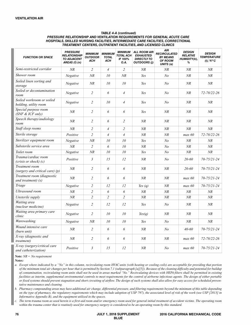
76
Note: NR = No requirementNotes:a. Except where indicated by a “No” in this column, recirculating room HVAC units (with heating or cooling coils) are acceptable for providing that portion
of the minimum total air changes per hour that is permitted by Section 7.1 (subparagraph [a][5]). Because of the cleaning difficulty and potential for buildupof contamination, recirculating room units shall not be used in areas marked “No.” Recirculating devices with HEPA filters shall be permitted in existingfacilities as interim, supplemental environmental controls to meet requirements for the control of airborne infectious agents. The design of either portableor fixed systems should prevent stagnation and short circuiting of airflow. The design of such systems shall also allow for easy access for scheduled preven-tative maintenance and cleaning.
b. Pharmacy compounding areas may have additional air change, differential pressure, and filtering requirements beyond the minimum of this table dependingon the type of pharmacy, the regulatory requirements which may include adoption of USP 797), the associated level of risk of the work (see USP [2013] inInformative Appendix B), and the equipment utilized in the spaces.
c. The term trauma room as used herein is a first-aid room and/or emergency room used for general initial treatment of accident victims. The operating roomwithin the trauma center that is routinely used for emergency surgery is considered to be an operating room by this standard.
2016 CALIFORNIA MECHANICAL CODE
VENTILATION AIR
TABLE 4-A (continued)PRESSURE RELATIONSHIP AND VENTILATION REQUIREMENTS FOR GENERAL ACUTE CARE HOSPITALS, SKILLED NURSING FACILITIES, INTERMEDIATE CARE FACILITIES, CORRECTIONAL
TREATMENT CENTERS, OUTPATIENT FACILITIES, AND LICENSED CLINICS
FUNCTION OR SPACE
PRESSURE RELATIONSHIPTO ADJACENTAREAS (f) (n)
MINIMUMOUTDOORACH
MINIMUMTOTALACH
MINIMUMTOTAL ACHIF 100%O.A.
ALL ROOM AIREXHAUSTED DIRECTLY TOOUTDOORS (j)
AIR RECIRCULATEDBY MEANS OF ROOMUNITS (a)
DESIGN RELATIVE
HUMIDITY(k),%
DESIGN TEMPERATURE
(l),°F/°C
Semi-restricted corridor NR 2 4 2 NR NR NR NRShower room Negative NR 10 NR Yes No NR NRSoiled linen sorting andstorage Negative NR 10 10 Yes No NR NR
Soiled or decontaminationroom Negative 2 6 4 Yes No NR 72-78/22-26
Soiled workroom or soiledholding, utility room Negative 2 10 4 Yes No NR NR
Special purpose room(SNF & ICF only) NR 2 6 6 Yes NR NR NR
Speech therapy/audiologyroom NR 2 6 2 NR NR NR NR
Staff sleep rooms NR 2 4 2 NR NR NR NRSterile storage Positive 2 4 4 NR NR max 60 72-78/22-26Sterilizer equipment room Negative NR 10 10 Yes No NR NRSubsterile service area NR 2 6 10 NR No NR NRToilet room Negative NR 10 10 Yes No NR NRTrauma/cardiac room(crisis or shock) (c) Positive 3 15 12 NR No 20-60 70-75/21-24
Treatment room(surgery and critical care) (p) NR 2 6 6 NR NR 20-60 70-75/21-24
Treatment room (diagnosticand treatment) (x) NR 2 6 6 NR NR max 60 70-75/21-24
Triage Negative 2 12 12 Yes (q) NR max 60 70-75/21-24Ultrasound room NR 2 6 6 NR NR NR NRUnsterile supply NR 2 2 2 NR NR NR NRWaiting area(nuclear medicine) Negative 2 12 12 Yes No NR NR
Waiting area primary careclinic Negative 2 10 10 Yes(q) NR NR NR
Warewashing Negative NR 10 10 Yes No NR NRWound intensive care(burn unit) NR 2 6 6 NR No 40-60 70-75/21-24
X-ray (diagnostic andtreatment) NR 2 6 6 NR NR max 60 72-78/22-26
X-ray (surgery/critical careand catheterization) Positive 3 15 12 NR No max 60 70-75/21-24
JULY 1, 2018 SUPPLEMENTBLUE
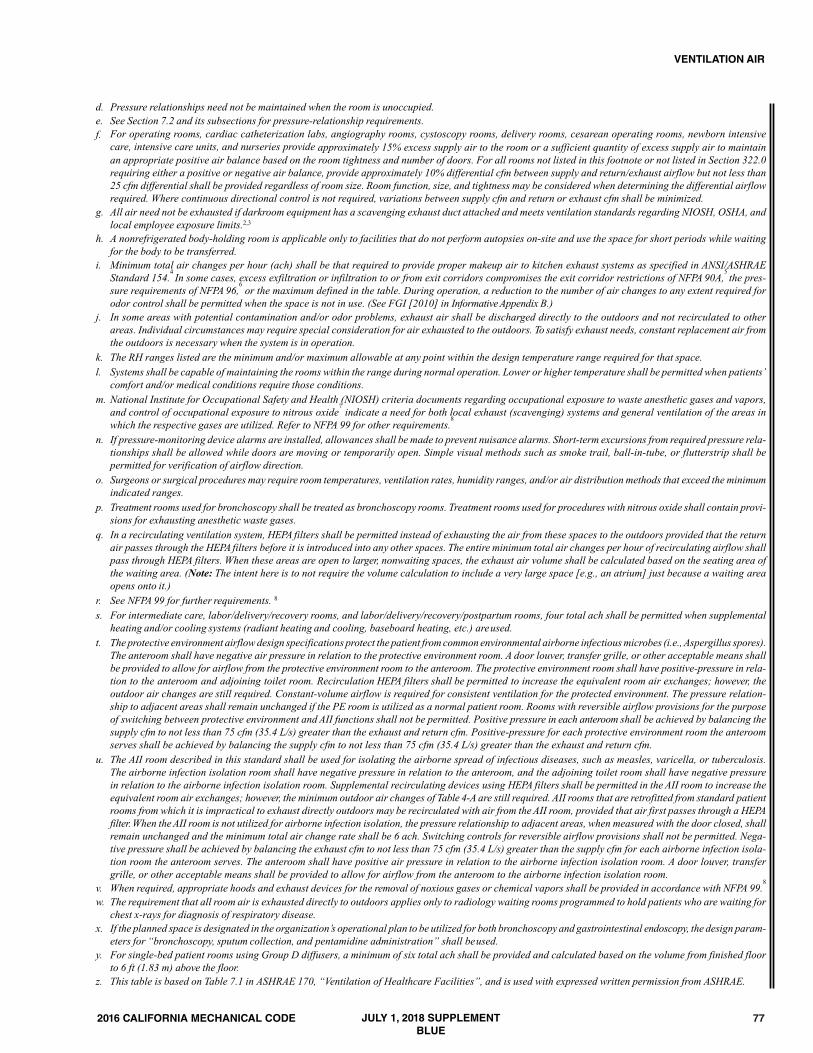
77
d. Pressure relationships need not be maintained when the room is unoccupied.e. See Section 7.2 and its subsections for pressure-relationship requirements.f. For operating rooms, cardiac catheterization labs, angiography rooms, cystoscopy rooms, delivery rooms, cesarean operating rooms, newborn intensive
care, intensive care units, and nurseries provide approximately 15% excess supply air to the room or a sufficient quantity of excess supply air to maintainan appropriate positive air balance based on the room tightness and number of doors. For all rooms not listed in this footnote or not listed in Section 322.0requiring either a positive or negative air balance, provide approximately 10% differential cfm between supply and return/exhaust airflow but not less than25 cfm differential shall be provided regardless of room size. Room function, size, and tightness may be considered when determining the differential airflowrequired. Where continuous directional control is not required, variations between supply cfm and return or exhaust cfm shall be minimized.
g. All air need not be exhausted if darkroom equipment has a scavenging exhaust duct attached and meets ventilation standards regarding NIOSH, OSHA, andlocal employee exposure limits.2,3
h. A nonrefrigerated body-holding room is applicable only to facilities that do not perform autopsies on-site and use the space for short periods while waitingfor the body to be transferred.
i. Minimum total air changes per hour (ach) shall be that required to provide proper makeup air to kitchen exhaust systems as specified in ANSI/ASHRAEStandard 154.
4 In some cases, excess exfiltration or infiltration to or from exit corridors compromises the exit corridor restrictions of NFPA 90A,
5 the pres-
sure requirements of NFPA 96,6
or the maximum defined in the table. During operation, a reduction to the number of air changes to any extent required forodor control shall be permitted when the space is not in use. (See FGI [2010] in InformativeAppendix B.)
j. In some areas with potential contamination and/or odor problems, exhaust air shall be discharged directly to the outdoors and not recirculated to otherareas. Individual circumstances may require special consideration for air exhausted to the outdoors. To satisfy exhaust needs, constant replacement air fromthe outdoors is necessary when the system is in operation.
k. The RH ranges listed are the minimum and/or maximum allowable at any point within the design temperature range required for that space.l. Systems shall be capable of maintaining the rooms within the range during normal operation. Lower or higher temperature shall be permitted when patients’
comfort and/or medical conditions require those conditions.m. National Institute for Occupational Safety and Health (NIOSH) criteria documents regarding occupational exposure to waste anesthetic gases and vapors,
and control of occupational exposure to nitrous oxide7
indicate a need for both local exhaust (scavenging) systems and general ventilation of the areas inwhich the respective gases are utilized. Refer to NFPA 99 for other requirements.
8
n. If pressure-monitoring device alarms are installed, allowances shall be made to prevent nuisance alarms. Short-term excursions from required pressure rela-tionships shall be allowed while doors are moving or temporarily open. Simple visual methods such as smoke trail, ball-in-tube, or flutterstrip shall bepermitted for verification of airflow direction.
o. Surgeons or surgical procedures may require room temperatures, ventilation rates, humidity ranges, and/or air distribution methods that exceed the minimumindicated ranges.
p. Treatment rooms used for bronchoscopy shall be treated as bronchoscopy rooms. Treatment rooms used for procedures with nitrous oxide shall contain provi-sions for exhausting anesthetic waste gases.
q. In a recirculating ventilation system, HEPA filters shall be permitted instead of exhausting the air from these spaces to the outdoors provided that the returnair passes through the HEPA filters before it is introduced into any other spaces. The entire minimum total air changes per hour of recirculating airflow shallpass through HEPA filters. When these areas are open to larger, nonwaiting spaces, the exhaust air volume shall be calculated based on the seating area ofthe waiting area. (Note: The intent here is to not require the volume calculation to include a very large space [e.g., an atrium] just because a waiting areaopens onto it.)
r. See NFPA 99 for further requirements. 8
s. For intermediate care, labor/delivery/recovery rooms, and labor/delivery/recovery/postpartum rooms, four total ach shall be permitted when supplementalheating and/or cooling systems (radiant heating and cooling, baseboard heating, etc.) areused.
t. The protective environment airflow design specifications protect the patient from common environmental airborne infectious microbes (i.e.,Aspergillus spores).The anteroom shall have negative air pressure in relation to the protective environment room. A door louver, transfer grille, or other acceptable means shallbe provided to allow for airflow from the protective environment room to the anteroom. The protective environment room shall have positive-pressure in rela-tion to the anteroom and adjoining toilet room. Recirculation HEPA filters shall be permitted to increase the equivalent room air exchanges; however, theoutdoor air changes are still required. Constant-volume airflow is required for consistent ventilation for the protected environment. The pressure relation-ship to adjacent areas shall remain unchanged if the PE room is utilized as a normal patient room. Rooms with reversible airflow provisions for the purposeof switching between protective environment and AII functions shall not be permitted. Positive pressure in each anteroom shall be achieved by balancing thesupply cfm to not less than 75 cfm (35.4 L/s) greater than the exhaust and return cfm. Positive-pressure for each protective environment room the anteroomserves shall be achieved by balancing the supply cfm to not less than 75 cfm (35.4 L/s) greater than the exhaust and return cfm.
u. The AII room described in this standard shall be used for isolating the airborne spread of infectious diseases, such as measles, varicella, or tuberculosis.The airborne infection isolation room shall have negative pressure in relation to the anteroom, and the adjoining toilet room shall have negative pressurein relation to the airborne infection isolation room. Supplemental recirculating devices using HEPA filters shall be permitted in the AII room to increase theequivalent room air exchanges; however, the minimum outdoor air changes of Table 4-A are still required. AII rooms that are retrofitted from standard patientrooms from which it is impractical to exhaust directly outdoors may be recirculated with air from the AII room, provided that air first passes through a HEPAfilter. When the AII room is not utilized for airborne infection isolation, the pressure relationship to adjacent areas, when measured with the door closed, shallremain unchanged and the minimum total air change rate shall be 6 ach. Switching controls for reversible airflow provisions shall not be permitted. Nega-tive pressure shall be achieved by balancing the exhaust cfm to not less than 75 cfm (35.4 L/s) greater than the supply cfm for each airborne infection isola-tion room the anteroom serves. The anteroom shall have positive air pressure in relation to the airborne infection isolation room. A door louver, transfergrille, or other acceptable means shall be provided to allow for airflow from the anteroom to the airborne infection isolation room.
v. When required, appropriate hoods and exhaust devices for the removal of noxious gases or chemical vapors shall be provided in accordance with NFPA 99.8
w. The requirement that all room air is exhausted directly to outdoors applies only to radiology waiting rooms programmed to hold patients who are waiting forchest x-rays for diagnosis of respiratory disease.
x. If the planned space is designated in the organization’s operational plan to be utilized for both bronchoscopy and gastrointestinal endoscopy, the design param-eters for “bronchoscopy, sputum collection, and pentamidine administration” shall beused.
y. For single-bed patient rooms using Group D diffusers, a minimum of six total ach shall be provided and calculated based on the volume from finished floorto 6 ft (1.83 m) above the floor.
z. This table is based on Table 7.1 in ASHRAE 170, “Ventilation of Healthcare Facilities”, and is used with expressed written permission from ASHRAE.
2016 CALIFORNIA MECHANICAL CODE
VENTILATION AIR
JULY 1, 2018 SUPPLEMENTBLUE
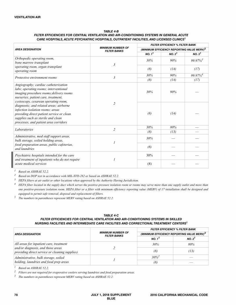
78 2016 CALIFORNIA MECHANICAL CODE
VENTILATION AIR
TABLE 4-BFILTER EFFICIENCIES FOR CENTRAL VENTILATION AND AIR-CONDITIONING SYSTEMS IN GENERAL ACUTE CARE HOSPITALS, ACUTE PSYCHIATRIC HOSPITALS, OUTPATIENT FACILITIES, AND LICENSED CLINICS1
AREA DESIGNATIONMINIMUM NUMBER OF
FILTER BANKS
FILTER EFFICIENCY % FILTER BANK
(MINIMUM EFFICIENCY REPORTING VALUE MERV)5
NO. 11 NO. 21 NO. 31
Orthopedic operating room, bone marrow transplantoperating room, organ transplantoperating room
330% 90% 99.97%3
(8) (14) (17)
Protective environment rooms 3 30% 90% 99.97%4
(8) (14) (17)Angiography; cardiac catheterizationlabs; operating rooms; interventional imaging procedure rooms;delivery roomsnurseries; patient care, treatment,cystoscopy, cesarean operating room,diagnostic, and related areas; airborneinfection isolation rooms; areasproviding direct patient service or cleansupplies such as sterile and cleanprocesses, and patient area corridors
2
30% 90% ––
(8) (14) ––
Laboratories 2 30% 80% ––(8) (13) ––
Administrative, med staff support areas,bulk storage, soiled holding areas,food preparation areas, public cafeterias, and laundries
130% –– ––
(8) –– ––
Psychiatric hospitals intended for the careand treatment of inpatients who do not requireacute medical services
130% –– ––
(8) –– ––
1 Based on ASHRAE 52.2.2 Based on DOP test in accordance with MIL-STD-282 or based on ASHRAE 52.2.3 HEPA filters at air outlet or other locations when approved by the Authority Having Jurisdiction.4 HEPA filter located in the supply duct which serves the positive-pressure isolation room or rooms may serve more than one supply outlet and more than
one positive-pressure isolation room. HEPA filter or a filter with minimum efficiency reporting value (MERV) of 17 installation shall be designed andequipped to permit safe removal, disposal and replacement of filters.
5 The numbers in parentheses represent MERV rating based on ASHRAE 52.2.
1 Based on ASHRAE 52.2.2 Filters are not required for evaporative coolers serving laundries and food preparation areas.3 The numbers in parentheses represent MERV rating based on ASHRAE 52.2.
TABLE 4-CFILTER EFFICIENCIES FOR CENTRAL VENTILATION AND AIR-CONDITIONING SYSTEMS IN SKILLED
NURSING FACILITIES AND INTERMEDIATE CARE FACILITIES AND CORRECTIONAL TREATMENT CENTERS1
AREA DESIGNATIONMINIMUM NUMBER OF
FILTER BANKS
FILTER EFFICIENCY % FILTER BANK
(MINIMUM EFFICIENCY REPORTING VALUE MERV)3
NO. 11 NO. 21
All areas for inpatient care, treatmentand/or diagnosis, and those areasproviding direct service or cleaning supplies)
230% 80%
(8) (13)
Administrative, bulk storage, soiledholding, laundries and food prep areas 1
30%2 ––(8) ––
JULY 1, 2018 SUPPLEMENTBLUE

792016 CALIFORNIA MECHANICAL CODE
VENTILATION AIR
TABLE 402.1MINIMUM VENTILATION RATES IN BREATHING ZONE1, 2, 4
[ASHRAE 62.1: TABLE 6.2.2.1]Note: Ventilation air supply requirements for occupancies regulated by the California Energy Commission are found in the California Energy Code.
OCCUPANCY CATEGORY4PEOPLE OUTDOOR
Air Rate RP (cfm/person)
AREA OUTDOORAir Rate RA(cfm/ft2)
DEFAULT OCCUPANTDensity3
(people/1000 ft2)
AIRCLASS
CORRECTIONAL FACILITIES
Booking/waiting 7.5 0.06 50 2Cell 5 0.12 25 2Day room 5 0.06 30 1Guard stations 5 0.06 15 1EDUCATIONAL FACILITIES
Art classroom 10 0.18 20 2Classrooms (ages 5-8) 10 0.12 25 1Classrooms (age 9 plus) 10 0.12 35 1Computer lab 10 0.12 25 1Daycare (through age 4) 10 0.18 25 2Daycare sickroom 10 0.18 25 3Lecture classroom 7.5 0.06 65 1Lecture hall (fixed seats) 7.5 0.06 150 1Media centera 10 0.12 25 1Multi-use assembly 7.5 0.06 100 1Music/theater/dance 10 0.06 35 1Science laboratories 10 0.18 25 2University/college laboratories 10 0.18 25 2Wood/metal shop 10 0.18 20 2FOOD AND BEVERAGE SERVICE
Bars, cocktail lounges 7.5 0.18 100 2Cafeteria/fast food dining 7.5 0.18 100 2Kitchen (cooking) 7.5 0.12 20 2Restaurant dining rooms 7.5 0.18 70 2GENERAL
Break rooms 5 0.06 25 1Coffee stations 5 0.06 20 1Conference/meeting 5 0.06 50 1Corridors – 0.06 – 1Occupiable storage rooms for liquids or gelsb 5 0.12 2 2HOTELS, MOTELS, RESORTS, DORMITORIES
Barracks sleeping areas 5 0.06 20 1Bedroom/living room 5 0.06 10 1Laundry rooms, central 5 0.12 10 2Laundry rooms within dwelling units 5 0.12 10 1Lobbies/pre-function 7.5 0.06 30 1Multipurpose assembly 5 0.06 120 1OFFICE BUILDINGS
Breakrooms 5 0.12 50 1Main entry lobbies 5 0.06 10 1Occupiable storage rooms for dry materials 5 0.06 2 1Office space 5 0.06 5 1Reception areas 5 0.06 30 1Telephone/data entry 5 0.06 60 1MISCELLANEOUS SPACES
Bank or bank lobbies 7.5 0.06 15 1Bank vaults/safe deposit 5 0.06 5 2Computer (not printing) 5 0.06 4 1Freezer and refrigerated spaces (<50°F)e 10 – – 2General manufacturing (excludes heavyindustrial and processes using chemicals) 10 0.18 7 3
JULY 1, 2018 SUPPLEMENTBLUE

80 2016 CALIFORNIA MECHANICAL CODE
VENTILATION AIR
TABLE 402.1 (continued)MINIMUM VENTILATION RATES IN BREATHING ZONE1, 2
[ASHRAE 62.1: TABLE 6.2.2.1]
OCCUPANCY CATEGORY4PEOPLE OUTDOOR
Air Rate RP (cfm/person)
AREA OUTDOORAir Rate RA(cfm/ft2)
DEFAULT OCCUPANTDensity3
(people/1000 ft2)
AIRCLASS
Pharmacy (prep. area) 5 0.18 10 2Photo studios 5 0.12 10 1Shipping/receivingb 10 0.12 2 2Sorting, packing, light assembly 7.5 0.12 7 2Telephone closets – – – 1Transportation waiting 7.5 0.06 100 1Warehousesb 10 0.06 – 2PUBLIC ASSEMBLY SPACES
Auditorium seating area 5 0.06 150 1Courtrooms 5 0.06 70 1Legislative chambers 5 0.06 50 1Libraries 5 0.12 10 1Lobbies 5 0.06 150 1Museums (children’s) 7.5 0.12 40 1Museums/galleries 7.5 0.06 40 1Places of religious worship 5 0.06 120 1RESIDENTIAL
Common corridors – 0.06 – 1Dwelling unitf, g 5 0.06 See footnotef 1RETAIL
Sales (except as below) 7.5 0.12 15 2Barber shop 7.5 0.06 25 2Beauty and nail salons 20 0.12 25 2Coin-operated laundries 7.5 0.12 20 2Mall common areas 7.5 0.06 40 1Pet shops (animal areas) 7.5 0.18 10 2Supermarket 7.5 0.06 8 1SPORTS AND ENTERTAINMENT
Bowling alley (seating) 10 0.12 40 1Disco/dance floors 20 0.06 100 2Gambling casinos 7.5 0.18 120 1Game arcades 7.5 0.18 20 1Gym, sports arena (play area)e 20 0.18 7 2Health club/aerobics room 20 0.06 40 2Health club/weight rooms 20 0.06 10 2Spectator areas 7.5 0.06 150 1Stages, studiosd 10 0.06 70 1Swimming (pool & deck)c – 0.48 – 2 For SI units: 1 cubic foot per minute = 0.0283 m3/min, 1 square foot = 0.0929 m2
Notes:1 This table applies to no-smoking areas. Rates for smoking-permitted spaces shall be determined using other methods.2 Volumetric airflow rates are based on an air density of 0.075 pounds of dry air per cubic foot (lbda/ft3) (1.201 kgda/m3), which corresponds to dry air at a
barometric pressure of 1 atm (101 kPa) and an air temperature of 70°F (21°C). Rates shall be permitted to be adjusted for actual density but such adjust-ment is not required for compliance with this chapter.
3 The default occupant density shall be used where actual occupant density is not known.4 Where the occupancy category for a proposed space or zone is not listed, the requirements for the listed occupancy category that is most similar in terms of
occupant density, activities, and building construction shall be used.
ITEM-SPECIFIC NOTES FOR TABLE 402.1a For high school and college libraries, use values shown for Public Assembly Spaces – Libraries.b Rate is capable of not being sufficient where stored materials include those having potentially harmful emissions.
JULY 1, 2018 SUPPLEMENTBLUE
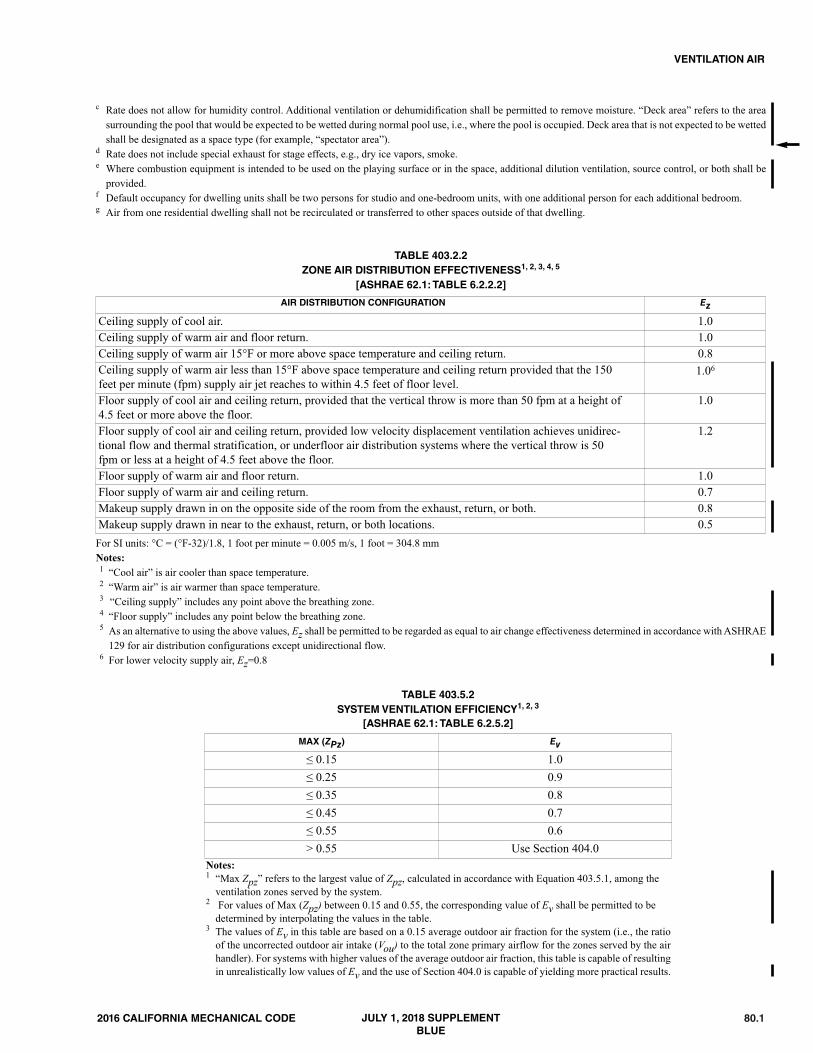
80.12016 CALIFORNIA MECHANICAL CODE
VENTILATION AIR
c Rate does not allow for humidity control. Additional ventilation or dehumidification shall be permitted to remove moisture. “Deck area” refers to the areasurrounding the pool that would be expected to be wetted during normal pool use, i.e., where the pool is occupied. Deck area that is not expected to be wettedshall be designated as a space type (for example, “spectator area”).
d Rate does not include special exhaust for stage effects, e.g., dry ice vapors, smoke.e Where combustion equipment is intended to be used on the playing surface or in the space, additional dilution ventilation, source control, or both shall be
provided.f Default occupancy for dwelling units shall be two persons for studio and one-bedroom units, with one additional person for each additional bedroom.g Air from one residential dwelling shall not be recirculated or transferred to other spaces outside of that dwelling.
AIR DISTRIBUTION CONFIGURATION Ez
Ceiling supply of cool air. 1.0Ceiling supply of warm air and floor return. 1.0Ceiling supply of warm air 15°F or more above space temperature and ceiling return. 0.8Ceiling supply of warm air less than 15°F above space temperature and ceiling return provided that the 150feet per minute (fpm) supply air jet reaches to within 4.5 feet of floor level.
1.06
Floor supply of cool air and ceiling return, provided that the vertical throw is more than 50 fpm at a height of4.5 feet or more above the floor.
1.0
Floor supply of cool air and ceiling return, provided low velocity displacement ventilation achieves unidirec-tional flow and thermal stratification, or underfloor air distribution systems where the vertical throw is 50fpm or less at a height of 4.5 feet above the floor.
1.2
Floor supply of warm air and floor return. 1.0Floor supply of warm air and ceiling return. 0.7Makeup supply drawn in on the opposite side of the room from the exhaust, return, or both. 0.8Makeup supply drawn in near to the exhaust, return, or both locations. 0.5
TABLE 403.2.2ZONE AIR DISTRIBUTION EFFECTIVENESS1, 2, 3, 4, 5
[ASHRAE 62.1: TABLE 6.2.2.2]
For SI units: °C = (°F-32)/1.8, 1 foot per minute = 0.005 m/s, 1 foot = 304.8 mmNotes:1 “Cool air” is air cooler than space temperature.2 “Warm air” is air warmer than space temperature.3 “Ceiling supply” includes any point above the breathing zone.4 “Floor supply” includes any point below the breathing zone.5 As an alternative to using the above values, Ez shall be permitted to be regarded as equal to air change effectiveness determined in accordance with ASHRAE
129 for air distribution configurations except unidirectional flow.6 For lower velocity supply air, Ez=0.8
Notes:1 “Max Zpz” refers to the largest value of Zpz, calculated in accordance with Equation 403.5.1, among the
ventilation zones served by the system. 2 For values of Max (Zpz) between 0.15 and 0.55, the corresponding value of Ev shall be permitted to be
determined by interpolating the values in the table.3 The values of Ev in this table are based on a 0.15 average outdoor air fraction for the system (i.e., the ratio
of the uncorrected outdoor air intake (Vou) to the total zone primary airflow for the zones served by the airhandler). For systems with higher values of the average outdoor air fraction, this table is capable of resultingin unrealistically low values of Ev and the use of Section 404.0 is capable of yielding more practical results.
MAX (ZPz) Ev
≤ 0.15 1.0≤ 0.25 0.9≤ 0.35 0.8≤ 0.45 0.7≤ 0.55 0.6> 0.55 Use Section 404.0
TABLE 403.5.2SYSTEM VENTILATION EFFICIENCY1, 2, 3
[ASHRAE 62.1: TABLE 6.2.5.2]
JULY 1, 2018 SUPPLEMENTBLUE
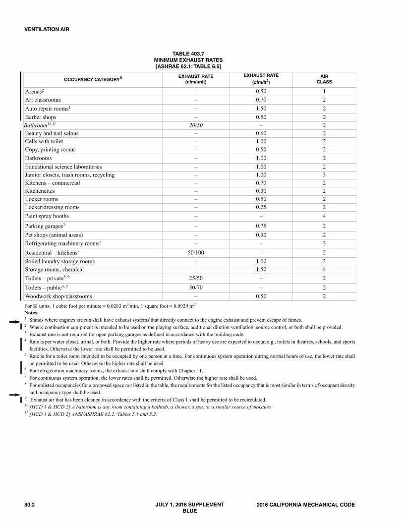
80.2 2016 CALIFORNIA MECHANICAL CODE
VENTILATION AIR
TABLE 403.7MINIMUM EXHAUST RATES[ASHRAE 62.1: TABLE 6.5]
OCCUPANCY CATEGORY8EXHAUST RATE
(cfm/unit)EXHAUST RATE
(cfm/ft2)AIR
CLASS
Arenas2 – 0.50 1Art classrooms – 0.70 2Auto repair rooms1 – 1.50 2Barber shops – 0.50 2Bathroom10,11 20/50 – 2Beauty and nail salons – 0.60 2Cells with toilet – 1.00 2Copy, printing rooms – 0.50 2Darkrooms – 1.00 2Educational science laboratories – 1.00 2Janitor closets, trash rooms, recycling – 1.00 3Kitchens – commercial – 0.70 2Kitchenettes – 0.30 2Locker rooms – 0.50 2Locker/dressing rooms – 0.25 2Paint spray booths – – 4
Parking garages3 – 0.75 2Pet shops (animal areas) – 0.90 2Refrigerating machinery rooms6 – – 3Residential – kitchens7 50/100 – 2Soiled laundry storage rooms – 1.00 3Storage rooms, chemical – 1.50 4Toilets – private5, 9 25/50 – 2Toilets – public4, 9 50/70 – 2Woodwork shop/classrooms – 0.50 2For SI units: 1 cubic foot per minute = 0.0283 m3⁄min, 1 square foot = 0.0929 m2
Notes:1 Stands where engines are run shall have exhaust systems that directly connect to the engine exhaust and prevent escape of fumes.2 Where combustion equipment is intended to be used on the playing surface, additional dilution ventilation, source control, or both shall be provided.3 Exhaust rate is not required for open parking garages as defined in accordance with the building code. 4 Rate is per water closet, urinal, or both. Provide the higher rate where periods of heavy use are expected to occur, e.g., toilets in theatres, schools, and sports
facilities. Otherwise the lower rate shall be permitted to be used.5 Rate is for a toilet room intended to be occupied by one person at a time. For continuous system operation during normal hours of use, the lower rate shall
be permitted to be used. Otherwise the higher rate shall be used.6 For refrigeration machinery rooms, the exhaust rate shall comply with Chapter 11.7 For continuous system operation, the lower rates shall be permitted. Otherwise the higher rate shall be used.8 For unlisted occupancies for a proposed space not listed in the table, the requirements for the listed occupancy that is most similar in terms of occupant density
and occupancy type shall be used.9 Exhaust air that has been cleaned in accordance with the criteria of Class 1 shall be permitted to be recirculated.10 [HCD 1 & HCD 2] A bathroom is any room containing a bathtub, a shower, a spa, or a similar source of moisture.11 [HCD 1 & HCD 2] ANSI/ASHRAE 62.2: Tables 5.1 and 5.2.
JULY 1, 2018 SUPPLEMENTBLUE

812016 CALIFORNIA MECHANICAL CODE
CALIFORNIA MECHANICAL CODE – MATRIX ADOPTION TABLE CHAPTER 5 – EXHAUST SYSTEMS
(Matrix Adoption Tables are non-regulatory, intended only as an aid to the code user. See Chapter 1 for state agency authority and building applications.)
Adopting Agency BSCBSC-CG
SFMHCD DSA OSHPD
BSCC DPH AGR DWR CEC CA SL SLC1 2 1-AC AC SS SS/CC 1 2 3 4
Adopt Entire Chapter X X X
Adopt Entire Chapteras amended (amendedsections listed below)
X X X X X X X X
Adopt only thosesections that are listedbelow X X
Chapter/Section
503.3 X X X
503.3 Exception 1 & 2 X X X
503.3.1 X X X
504.1.1 X X X
505.7 X
505.7.1 X
508.5 X X X
509.2.3 X
509.2.3.4 X
511.1.6 X X X
513.2.2 X X X
513.2.2 Exception 2 X X
513.3.2 X
513.11 X
513.11.1 X
516.2.7 Exception X
516.2.9 XThis state agency does not adopt sections identified with the following symbol: †The Office of the State Fire Marshal’s adoption of this chapter or individual sections is applicable to structures regulated by other state agencies pursuant toSection 1.11.
JULY 1, 2018 SUPPLEMENTBLUE

82 2016 CALIFORNIA MECHANICAL CODE

501.0 General.501.1 Applicability. This chapter includes requirements forenvironmental air ducts, product-conveying systems, andcommercial hoods and kitchen ventilation. Part I addressesenvironmental air ducts and product conveying systems. PartII addresses commercial hoods and kitchen ventilation.
502.0 Termination.502.1 Exhaust Opening Protection. Exhaust openingsterminating to the outdoors shall be covered with a corrosion-resistant screen having not less than 1⁄4 of an inch (6.4 mm)openings, and shall have not more than 1⁄2 of an inch (12.7mm) openings.Exception: Clothes dryers.502.2 Termination of Exhaust Ducts. Exhaust ducts shallterminate in accordance with Section 502.2.1 through Section502.2.3.
502.2.1 Environmental Air Ducts. Environmental airduct exhaust shall terminate not less than 3 feet (914 mm)from a property line, 10 feet (3048 mm) from a forcedair inlet, and 3 feet (914 mm) from openings into thebuilding. Environmental exhaust ducts shall notdischarge onto a public walkway.502.2.2 Product Conveying Ducts. Ducts conveyingexplosive or flammable vapors, fumes, or dusts shallterminate not less than 30 feet (9144 mm) from a propertyline, 10 feet (3048 mm) from openings into the building,6 feet (1829 mm) from exterior walls or roofs, 30 feet(9144 mm) from combustible walls or openings into thebuilding that are in the direction of the exhaust discharge,and 10 feet (3048 mm) above adjoining grade.
Other product-conveying outlets shall terminate notless than 10 feet (3048 mm) from a property line, 3 feet(914 mm) from exterior walls or roofs, 10 feet (3048mm) from openings into the building, and 10 feet (3048mm) above adjoining grade.502.2.3 Commercial Kitchen Ducts. Commercialkitchens exhaust ducts shall terminate in accordance withSection 510.9 or Section 510.10.
Part I – Environmental Air Ducts and Product-Conveying Systems.
503.0 Motors, Fans, and Filters.503.1 General. Motors and fans shall be sized to provide therequired air movement. Motors in areas that contain flam-mable vapors or dusts shall be of a type approved for suchenvironments. A manually operated remote control installedat an approved location shall be provided to shut off fans orblowers in flammable vapor or dust systems. Equipment used
in operations that generate explosive or flammable vapors,fumes, or dusts shall be interlocked with the ventilationsystem so that the equipment cannot be operated unless theventilation fans are in operation. Motors for fans used toconvey flammable vapors or dusts shall be located outsidethe duct or shall be protected with approved shields and dust-proofing. Where belts are used, they shall not enter the ductunless the belt and pulley within the duct are enclosed.Motors and fans shall be accessible for servicing and main-tenance.503.2 Fans. Parts of fans in contact with explosive or flam-mable vapors, fumes, or dusts shall be of nonferrous ornonsparking materials or their casing shall be lined orconstructed of such material. Where the size and hardness ofmaterials passing through a fan are capable of producing aspark, both the fan and the casing shall be of nonsparkingmaterials. Where fans are required to be spark-resistant, theirbearings shall not be within the airstream, and parts of the fanshall be grounded. Fans in systems handling materials thatare likely to clog the blades, and fans in buffing or wood-working exhaust systems, shall be of the radial-blade ortube-axial type.
Equipment used to exhaust explosive or flammablevapors, fumes, or dusts shall bear an identification platestating the ventilation rate for which the system was designed.
Fans located in systems conveying corrosives shall be ofmaterials that are resistant to the corrosive or shall be coatedwith corrosion-resistant materials.503.3 Filters. [BSC-CG], [DSA-SS & DSA-SS/CC] Inmechanically ventilated buildings, provide regularly occu-pied areas of the building with air filtration media for outsideand return air that provides at least a Minimum EfficiencyReporting Value (MERV) of 8. MERV 8 filters shall beinstalled prior to occupancy, and recommendations for main-tenance with filters of the same value shall be included in theoperation and maintenance manual in compliance withChapter 5, Division 5.5. of the California Green BuildingStandards Code (CALGreen).Exceptions:1. An ASHRAE 10-percent to 15-percent efficiency filter
shall be permitted for an HVAC unit meeting the 2013California Energy Code having 60,000 Btu/h (17.6 kW)or less capacity per fan coil, if the energy use of the airdelivery system is 0.4 W/cfm [848 W/(m3/s)] or less atdesign air flow.
2. Existing mechanical equipment. 503.3.1 Labeling. Installed filters shall be clearlylabeled by the manufacturer indicating the MERV rating.
504.0 Environmental Air Ducts.504.1 General. Where not specified in this chapter, exhaustducts shall be constructed and installed in accordance with
2016 CALIFORNIA MECHANICAL CODE 83
CHAPTER 5EXHAUST SYSTEMS
»
»
JULY 1, 2018 SUPPLEMENTBLUE

84 2016 CALIFORNIA MECHANICAL CODE
Chapter 6 and shall be airtight as approved by the AuthorityHaving Jurisdiction. Environmental air ducts that have an alter-nate function as a part of an approved smoke-control systemdo not require design as Class 1 product-conveying ducts.Exceptions:(1) Ductless range hoods where installed in accordance with
the manufacturer’s installation instructions.(2) Condensing clothes dryers where installed in accordance
with the manufacturer’s installation instructions.504.1.1 Backdraft Protection. Exhaust ducts shallterminate outside the building and shall be equipped withbackdraft dampers or with motorized dampers that auto-matically shut where the systems or spaces served arenot in use. [OSHPD 1, 2 & 4] Exception: Backdraftdampers are not required when the exhaust fan mustoperate continuously.Exception: Where the exhaust duct does not dischargeinto a common exhaust plenum and one of the following:(1) The exhaust fan runs continuously.(2) The exhaust duct serves space(s) that are not mechan-
ically heated or cooled.(3) The space served is maintained at positive pressure.
504.2 Independent Exhaust Systems. Single or combinedmechanical exhaust systems shall be independent of otherexhaust systems.504.3 Domestic Range. Ducts used for domestic kitchenrange ventilation shall be of metal and shall have smooth inte-rior surfaces.Exception:Ducts for domestic kitchen downdraft grill-rangeventilation installed under a concrete slab floor shall bepermitted to be of approved Schedule 40 PVC provided:(1) The under-floor trench in which the duct is installed shall
be completely backfilled with sand or gravel.(2) Not more than 1 inch (25.4 mm) of 6 inch diameter (152
mm) PVC coupling shall be permitted to protrude abovethe concrete floor surface.
(3) PVC pipe joints shall be solvent cemented to provide anair and greasetight duct.
(4) The duct shall terminate above grade outside the buildingand shall be equipped with a back-draft damper.
504.4 Clothes Dryers. A clothes dryer exhaust duct shall notbe connected to a vent connector, gas vent, chimney, and shallnot terminate into a crawl space, attic, or other concealedspace. Exhaust ducts shall not be assembled with screws orother fastening means that extend into the duct and that arecapable of catching lint, and that reduce the efficiency of theexhaust system. Exhaust ducts shall be constructed of rigidmetallic material. Transition ducts used to connect the dryerto the exhaust duct shall be listed for that application orinstalled in accordance with the clothes dryer manufacturer’sinstallation instructions. Clothes dryer exhaust ducts shallterminate to the outside of the building in accordance withSection 502.2.1 and shall be equipped with a backdraftdamper. Screens shall not be installed at the duct termination.
Devices, such as fire or smoke dampers, that will obstruct theflow of the exhaust shall not be used. Where joining of ducts,the male end shall be inserted in the direction of airflow.
504.4.1 Provisions for Makeup Air. Makeup air shallbe provided in accordance with the following:(1) Makeup air shall be provided for Type 1 clothes
dryers in accordance with the manufacturer’sinstructions. [NFPA 54:10.4.3.1]. Where a closet isdesigned for the installation of a clothes dryer, anopening of not less than 100 square inches (0.065m2) for makeup air shall be provided in the door orby other approved means.
(2) Provision for makeup air shall be provided for Type2 clothes dryers, with a free area of not less than 1square inch (0.0006 m2) for each 1000 Britishthermal units per hour (Btu/h) (0.293 kW) total inputrating of the dryer(s) installed. [NFPA 54:10.4.3.2]
504.4.2 Domestic Clothes Dryers. Where a compartmentor space for a Type 1 clothes dryer is provided, not lessthan a 4 inch diameter (102 mm) exhaust duct of approvedmaterial shall be installed in accordance with Section504.0.
Type 1 clothes dryer exhaust ducts shall be of rigidmetal and shall have smooth interior surfaces. The diam-eter shall be not less than 4 inches nominal (100 mm)and the thickness shall be not less than 0.016 of an inch(0.406 mm).
504.4.2.1 Length Limitation. Unless otherwisepermitted or required by the dryer manufacturer’sinstructions and approved by the Authority HavingJurisdiction, domestic dryer moisture exhaust ductsshall not exceed a total combined horizontal andvertical length of 14 feet (4267 mm), including two90 degree (1.57 rad) elbows. A length of 2 feet (610mm) shall be deducted for each 90 degree (1.57 rad)elbow in excess of two.504.4.2.2 Transition Ducts. Listed clothes dryertransition ducts not more than 6 feet (1829 mm) inlength shall be permitted to be used to connect theType 1 dryer to the exhaust ducts. Transition ductsand flexible clothes dryer transition ducts shall notbe concealed within construction, and shall beinstalled in accordance with the manufacturer’sinstallation instructions.
504.4.3 Commercial Clothes Dryers. Commercialdryer exhaust ducts shall be installed in accordance withtheir listings. The installation of commercial clothesdryer exhaust ducts shall comply with the appliancemanufacturer’s installation instructions.
504.4.3.1 Exhaust Ducts for Type 2 ClothesDryers. Exhaust ducts for Type 2 clothes dryersshall comply with the following:(1) Exhaust ducts for Type 2 clothes dryers shall
comply with Section 504.4. [NFPA 54:10.4.5.1](2) Exhaust ducts for Type 2 clothes dryers shall be
constructed of sheet metal or other noncom-
EXHAUST SYSTEMS
»
«
«
«»
«
«
1052016 CALIFORNIA MECHANICAL CODE
EXHAUST SYSTEMS
513.0 Fire-Extinguishing Equipment.513.1 General. Fire-extinguishing equipment for the protectionof grease removal devices, hood exhaust plenums, and exhaustduct systems shall be provided. [NFPA 96:10.1.1]
513.1.1 Protection. Cooking equipment that producesgrease-laden vapors and is capable of being a source ofignition of grease in the hood, grease removal device,or duct shall be protected by fire-extinguishing equip-ment. [NFPA 96:10.1.2]
513.2 Types of Equipment. Fire-extinguishing equipmentshall include both automatic fire-extinguishing systems asprimary protection and portable fire extinguishers assecondary backup. [NFPA 96:10.2.1]
513.2.1 Identification.A placard shall be conspicuouslyplaced near the fire extinguisher that states that the fireprotection system shall be activated prior to using the fire-extinguisher. [NFPA 96:10.2.2]513.2.2 Standard. Commercial cooking equipment thatproduce grease laden vapors shall be provided with aType I Hood, in accordance with this Code, and an auto-matic fire extinguishing system that is listed and labeledfor its intended use as follows:(1) Wet chemical extinguishing system (NFPA 17A, Stan-
dard for Wet Chemical Extinguishing Systems),complying with UL 300, Fire Testing of Fire Extin-guishing Systems for Protection of RestaurantCooking Equipment. All existing dry chemical andwet chemical extinguishing systems shall comply withUL 300, Fire Testing of Fire Extinguishing Systemsfor Protection of Restaurant Cooking Equipment.
(2) Carbon dioxide extinguishing systems (NFPA 12,Standard on Carbon Dioxide ExtinguishingSystems).
(3) Automatic fire sprinkler systems (NFPA 13, Stan-dard for the Installation of Sprinkler Systems).
All existing dry chemical and wet chemical extinguishingsystems shall comply with UL 300, no later than thesecond required servicing of the system following theeffective date of this section.Exceptions:(1) Automatic fire-extinguishing equipment provided as
part of listed recirculating systems in accordancewith UL 710B. [NFPA 96:10.2.5]
(2) [DSA-SS and DSA-SS/CC] Public schools kitchens,without deep-fat fryers, shall be upgraded to a UL300, Fire Testing of Fire Extinguishing Systems forProtection of Restaurant Cooking Equipment,compliant system during state-funded modernizationprojects that are under the jurisdiction of the Divi-sion of the State Architect.
513.2.4 Modification of Existing Hood Systems. Anabandoned pipe or conduit from a previous installationshall be removed from within the hood, plenum, andexhaust duct. [NFPA 96:10.2.7.1]
513.2.4.1 Sealing. Penetrations and holes resultingfrom the removal of conduit or piping shall be sealedwith listed or equivalent liquid-tight sealing devices.[NFPA 96:10.2.7.2]
513.2.4.2 Obstructions.The addition of obstructionsto spray patterns from the cooking appliance nozzle(s)such as baffle plates, shelves, or a modification shallnot be permitted. [NFPA 96:10.2.7.3]513.2.4.3 System Re-evaluation. Changes or modi-fications to the hazard after installation of the fire-extinguishing systems shall result in re-evaluationof the system design by a properly trained, qualified,and certified person(s). [NFPA 96:10.2.7.4]
513.2.5 Fixed Baffle Hoods with Water Wash. Greaseremoval devices, hood exhaust plenums, and exhaust ductsrequiring protection in accordance with Section 513.1shall be permitted to be protected by a listed fixed bafflehood containing a constant or fire-actuated water washsystem that is listed and in accordance with UL 300 orother equivalent standards and shall be installed in accor-dance with the requirements of their listing. [NFPA96:10.2.8.1]
513.2.5.1 Domestic Water Supply. The water forlisted, fixed baffle hood assemblies shall bepermitted to be supplied from the domestic watersupply where the minimum water pressure and floware provided in accordance with the terms of thelisting. [NFPA 96:10.2.8.3]513.2.5.2 Control Valve. The water supply shall becontrolled by a supervised water supply controlvalve. [NFPA 96:10.2.8.4]513.2.5.3 Activation. The water wash in the fixedbaffle hood specifically listed to extinguish a fireshall be activated by the cooking equipment extin-guishing system. [NFPA 96:10.2.8.5]513.2.5.4 Water-Wash System. A water-washsystem approved to be used for protection of thegrease removal device(s), hood exhaust plenum(s),exhaust duct(s), or combination thereof shall includeinstruction and electrical interface for simultaneousactivation of the water-wash system from an auto-matic fire-extinguishing system, where the auto-matic fire-extinguishing system is used for cookingequipment protection. [NFPA 96:10.2.8.6]513.2.5.5 Exception. Where the fire-extinguishingsystem provides protection for the cooking equip-ment, hood, and duct, activation of the water-washshall not be required. [NFPA 96:10.2.8.7]513.2.5.6 Water Supply. The water required forlisted automatic fire-extinguishing systems shall bepermitted to be supplied from the domestic watersupply where the minimum water pressure and floware provided in accordance with the terms of thelisting. The water supply shall be controlled by asupervised water supply control valve. Where thewater supply is from a dedicated fire protectionwater supply in a building with one or more firesprinkler systems, separate indicating control valvesand drains shall be provided and arranged so that thehood system and sprinkler system are capable ofbeing controlled individually. [NFPA 96:10.2.9]
JULY 1, 2018 SUPPLEMENTBLUE

106 2016 CALIFORNIA MECHANICAL CODE
513.2.6 Water Valve Supervision.Valves controlling thewater supply to listed fixed baffle hood assemblies, auto-matic fire-extinguishing systems, or both shall be listedindicating type of valve and shall be supervised open byone of the following methods:(1) Central station, proprietary, or remote station alarm
service.(2) Local alarm service that will cause the sounding of
an audible signal at a constantly attended point. (3) Locking valves open. (4) Sealing of valves and approved weekly recorded
inspection. [NFPA 96:10.2.10]513.3 Simultaneous Operation. Fixed pipe extinguishingsystems in a single hazard area shall be arranged for simulta-neous automatic operation upon actuation of any one of thesystems. [NFPA 96:10.3.1]
513.3.1 Automatic Sprinkler System. Simultaneousoperation shall not be required where the one fixed pipeextinguishing system is an automatic sprinkler system.Where an automatic sprinkler system is used in conjunc-tion with a water-based fire-extinguishing system servedby the same water supply, hydraulic calculations shallconsider both systems operating simultaneously. [NFPA96:10.3.2, 10.3.2.1]513.3.2 Dry or Wet Chemical Systems. Simultaneousoperation shall be required where a dry or wet chemicalsystem is used to protect common exhaust ductwork byNFPA 17A, Wet Chemical Extinguishing Systems.
513.4 Fuel and Electric Power Shutoff. Upon activation of afire-extinguishing system for a cooking operation, sources offuel and electric power that produce heat to equipment requiringprotection by that system shall automatically shut off. [NFPA96:10.4.1]Exception: Solid-fuel cooking operations.
513.4.1 Steam. Steam supplied from an external sourceshall not be required to automatically shut off. [NFPA96:10.4.2]513.4.2 Protection Not Required. A gas appliancenot requiring protection, but located under ventilatingequipment where protected appliances are located, shallbe automatically shut off upon activation of the extin-guishing system. [NFPA 96:10.4.3]513.4.3 Manual Reset. Shutoff devices shall requiremanual reset. [NFPA 96:10.4.4]
513.5 Manual Activation. A readily accessible means formanual activation shall be located between 42 inches and 48inches (1067 mm and 1219 mm) above the floor, be acces-sible in the event of a fire, be located in a path of egress, andclearly identify the hazard protected. Not less than onemanual actuation device shall be located not less than 10 feet(3048 mm) and not more than 20 feet (6096 mm) from theprotected exhaust system(s) within the path of egress or at analternative location acceptable to the Authority Having Juris-diction. Manual actuation using a cable-operated pull station
shall not require more than 40 pounds-force (lbf) (178 N) offorce, with a pull movement not to exceed 14 inches (356mm) to activate the automatic fire extinguishing system. Theautomatic and manual means of system activation external tothe control head or releasing device shall be separate andindependent of each other so that failure of one will notimpair the operation of the other except as permitted inSection 513.5.1. [NFPA 96:10.5.1 – 10.5.2]
513.5.1 Location of Manual Activation Device. Themanual means of system activation shall be permitted tobe common with the automatic means where the manualactivation device is located between the control head orreleasing device and the first fusible link. [NFPA96:10.5.3]513.5.2 Automatic Sprinkler System.An automatic sprin-kler system shall not require a manual means of systemactivation. [NFPA 96:10.5.4]513.5.3 Manual Actuator(s). The means for manual acti-vation shall be mechanical or rely on electrical power foractivation in accordance with Section 513.5.4. [NFPA96:10.5.5]513.5.4 Standby Power Supply. Electrical power shallbe permitted to be used for manual activation where astandby power supply is provided or where supervisionis provided in accordance with Section 513.7. [NFPA96:10.5.6]
513.6 System Annunciation. Upon activation of an auto-matic fire-extinguishing system, an audible alarm or visualindicator shall be provided to show that the system has acti-vated. [NFPA 96:10.6.1]
513.6.1 Signaling.Where a fire alarm signaling system isserving the occupancy where the extinguishing system islocated, the activation of the automatic fire-extinguishingsystem shall activate the fire alarm signaling system.[NFPA 96:10.6.2]
513.7 System Supervision. Where electrical power is requiredto operate the fixed automatic fire-extinguishing system, thesystem shall be provided with a reserve power supply and bemonitored by a supervisory alarm except as permitted inaccordance with Section 513.7.1. [NFPA 96:10.7.1]
513.7.1 Automatic Fire-Extinguishing System.Where afixed automatic fire-extinguishing system includes auto-matic mechanical detection and actuation as a backupdetection system, electrical power monitoring and reservepower supply shall not be required. [NFPA 96:10.7.2]513.7.2 Supervision. System supervision shall not berequired where a fire-extinguishing system(s) is inter-connected or interlocked with the cooking equipmentpower source(s) so that where the fire-extinguishingsystem becomes inoperable due to power failure, sourcesof fuel or electric power that produce heat to cookingequipment serviced by that hood shall automatically shutoff. [NFPA 96:10.7.3]513.7.3 Listed Water Wash System. System supervi-sion shall not be required where an automatic fire-extin-guishing system, including automatic mechanical
EXHAUST SYSTEMS

For prior history, see the History Note Appendix to the Cali-fornia Mechanical Code, 2013 Triennial Edition effectiveJanuary 1, 2014.
1. (BSC 02/15, HCD 05/15, DSA-SS 06/15, OSHPD 06/15,SFM 03/15) Adoption by reference of the 2015 UniformMechanical Code (UMC) with necessary state amend-ments and repeal of the 2012 edition of the UMC; Effec-tive on January 1, 2017.
2. Errata to correct editorial errors within the preface aswell as throughout various chapters in this code. Effec-tive January 1, 2017.
3. 2016 Intervening Update (DSA-SS/CC 03/16) Adoptedby the California Building Standards Commission onJune 20, 2017, published on January 1, 2018, effectiveon July 1, 2018.
4. 2016 Intervening Update (OSHPD 04/16) Adopted by theCalifornia Building Standards Commission on August14, 2017, published on January 1, 2018, effective on July1, 2018.
4912016 CALIFORNIA MECHANICAL CODE
HISTORY NOTE APPENDIXCALIFORNIA MECHANICAL CODE
(TITLE 24, PART 4, CALIFORNIA CODE OF REGULATIONS)
JULY 1, 2018 SUPPLEMENTBLUE

492 2016 CALIFORNIA MECHANICAL CODE