rf power sources - jacow home pageepaper.kek.jp/.../j_jacob_rf-power-sources_talk.pdfpower supply...
TRANSCRIPT

SRF’2009 – 18th Sept. 2009 Tutorial: RF Power Sources J. Jacob, slide 1
SRF’2009 tutorial program
RF Power Sources
Jörn Jacob, ESRF

SRF’2009 – 18th Sept. 2009 Tutorial: RF Power Sources J. Jacob, slide 2
Auxiliaries
RF transmitters for accelerating cavities
Master Source LLRF
RF distribution
Pre-ampl.
Power Amplifier
Waveguide
Accelerating Cavity
Circulator
Load• Power Supply
• Modulator
• Amplitude loop• Phase loop
(or IQ loop)• Cavity tuning loop• Cavity protection
This hour’s subject:
RF Power Sources

SRF’2009 – 18th Sept. 2009 Tutorial: RF Power Sources J. Jacob, slide 3
Starting point: specification
• Frequency: 100 MHz … 10 GHz
• Operation: cw or pulsed
• Power: 10 kW (cw)… 100 MW (pulsed)
• Gain
• Efficiency [mains to RF conversion]
• Stability, Phase noise: amplifier & power supply / modulator
• For instance, modern light Sources, in particular FEL require extremely small phase jitter (< 0.1…0.01 deg) and voltage ripple (< 0.1…0.01 %)
• Reliability, MTBF
• Durability
• Availability
• Cost: procurement, operation, maintenance

SRF’2009 – 18th Sept. 2009 Tutorial: RF Power Sources J. Jacob, slide 4
0.1
1
10
100
1000
10000
100000
10 100 1000 10000 100000
f [MHz]
RF
Pow
er [
kW]
RF power sources for accelerating cavities
Tetrodes
Diacrode
Transistor amplifiers ≈ 300 W / unit
x 600
IOTs
CW Klystrons
Pulsed KlystronsMBK
PPM
CW
or A
vera
geP
ulse
d

SRF’2009 – 18th Sept. 2009 Tutorial: RF Power Sources J. Jacob, slide 5
Other RF power sources
Other sources generally not used to power accelerating cavities• Gyrotrons: typically 90…170 GHz, 1 MW, 5 …10 s pulses for plasma heating (fusion) and
industrial applications
• TWT: broadband RF tube, used in some broadband feedback systems
• Magnetrons: RF oscillator source
• …

SRF’2009 – 18th Sept. 2009 Tutorial: RF Power Sources J. Jacob, slide 6
Tetrode• Tetrode:
• Vacuum tube with intensity modulation of the electron beam
• Accelerator applications up to 300…400 MHz: finite electron drift time limits the achievable gain at much higher frequencies
• Tetrode transmitters deliver between 10 kW and 2 MW CW or average power, correspondingly more in pulsed mode.
• Diacrode TH 628 / Thales:• With its symmetric geometry optimized for the
coupling to a λ/2 coaxial resonator, the diacrode achieves twice as much frequency-power product as a conventional tetrode
• 200 MHz: 1 MW cw
4.5 MW in 500 μs pulses / 1 % duty cycle

SRF’2009 – 18th Sept. 2009 Tutorial: RF Power Sources J. Jacob, slide 7
Klystron
• Low power Velocity modulation with input cavity
• Drift space exploited in conjunction with several idle cavities to achieve bunching and therefore high efficient DC to RF power conversion:
• High gain
• Idc = K Vdc3/2 , for reasonable efficiency: beam perveance K < 1 μPerv
High RF power ⇒ High Voltage
Increased effective perveance ⇒ Multibeam klystron
• CW klystrons often have a modulating anode for:gain control
while RF drive power in saturation
allowing high efficiency operation over large dynamic range
However: anode modulation has low bandwidth (typically < 10 Hz)
FilamentCathode
Modulating Anode for good η at lower Power
Collector
RF in RF out
SRF’2009 – 18th Sept. 2009 Tutorial: RF Power Sources J. Jacob, slide 8
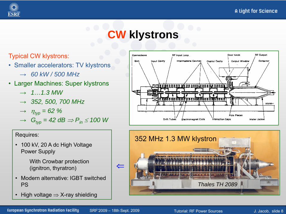
CW klystrons
Typical CW klystrons:• Smaller accelerators: TV klystrons
→ 60 kW / 500 MHz • Larger Machines: Super klystrons
→ 1…1.3 MW → 352, 500, 700 MHz→ ηtyp = 62 %→ Gtyp = 42 dB ⇒ Pin ≤ 100 W
352 MHz 1.3 MW klystron
Thales TH 2089
Requires:
• 100 kV, 20 A dc High Voltage Power Supply
With Crowbar protection (ignitron, thyratron)
• Modern alternative: IGBT switched PS
• High voltage ⇒ X-ray shielding
⇐

SRF’2009 – 18th Sept. 2009 Tutorial: RF Power Sources J. Jacob, slide 9
Example - ESRF Storage Ring: RF system in operation
High beam loading ⇒ Large dynamic range
• 1980’s: 1.3 MW - 352.2 MHz klystrons developed for LEP/CERN
• Late 1980’s:• ESRF = first 3rd generation
light source
• Power in the MW range
• No alternative to klystrons:
LEP RF system ⇒reference design for ESRF (transmitters & cavities)
• Similar choices by APS, Spring-8, others…
• ESRF: 14 years experience with these tubes from Philips, EEV, Thales

SRF’2009 – 18th Sept. 2009 Tutorial: RF Power Sources J. Jacob, slide 10
1.3 MW Klystrons: delicate to define working point
Once stable conditions ⇒ 1000’s of hours reliable operation
Problem Way out
Harmonic 2 up to 1 kW on probe klystron / circulator distance
Multipactoring in input cavity reduces usable dynamic range drive power, focusing
Gun breakdowns backwards ions, e- ⇒ x-rays, ceramics charging up focusing, conditioning
HV breakdownsconditioning
RF breakdowns in output coupler
Barium pollution from cathode overheating anode current, breakdowns
• regular heating adjustment• low heating when no beam
Sometimes retuning of cavities

SRF’2009 – 18th Sept. 2009 Tutorial: RF Power Sources J. Jacob, slide 11
High Power Klystrons at ESRF, continued…
Trip statistics:• Total RF system: 25% … 30% of machine trips (ESRF: MTBF > 2 days, availability > 98%)
• Klystron failure rate < auxiliaries’ failure rate: • Argument for small number / high power tubes
• 900 kW / 450 kW operation: same trip rate• Not much linked to power level
Typical klystron drawbacks:• dΦ/d(HV) ≈ 7 ° per % HV
• Phase noise up to -50 dBc at multiples of 300 Hz / HVPS ripples • Beam sensitive (fsynchrotron = 1.2 to 2 kHz) • Fast phase loop → -70 dBc• Better (in future): switched PS, high switching frequency
• Drive power close to saturation ⇒ reduced gain for fast RF feedback for high beam loading → at PEP II: digital klystron lineariser [J. Fox et al.]
• Today only one klystron supplier for 352 MHz 1.3 MW klystrons

SRF’2009 – 18th Sept. 2009 Tutorial: RF Power Sources J. Jacob, slide 12
Pulsed Klystrons - examples• S band klystron
• 35 … 45 MW at 3 GHz, pulses < 10 μs• SLAC and pre-injectors of many machines, including light sources
• Recent developments:• Multi Beam Klystron for high efficiency, ex: 1.3 GHz (Thales, CPI,
Toshiba)• Low Perveance to maximize η: 45 % → 65 %• High power: 10 MW / 1.5 ms pulses at “low” HV: 120 kV
⇒ cathode for several beams • TESLA, X-FEL, … [see e.g. XFEL TDR]
• Periodic Permanent Magnet – PPM klystrons• Example: 75 MW / 11.4 GHz for NLC: saving 80 MW of focus supply !
[Thales MBK] 7 beams
• Future: CLIC concept = very dedicated RF source
• 3 GHz / 937 MHz (CTF3/CLIC) high intensity drive beam →PETS: transfer ≈ 10 MW/cm at 30 GHz to high energy 3 TeV
Linac (recent modification: 12 GHz Linac achieving 100 MV/m)
[http://clic-study.web.cern.ch]

SRF’2009 – 18th Sept. 2009 Tutorial: RF Power Sources J. Jacob, slide 13
SLED – Pulse Compression
ϕ Linac
Klystron
3 dB -Coupler
2 Energy storage cavities
SLED = Stanford Linac Energy Doubler
SLED II: flatten pulses by replacing cavities with long resonant delay lines [Kroll et al., SLAC]
Klystron pulse
Phase shift
Linac pulse
0º
180º
t
Continuous phase shift [Fiebig & Schieblich, CERN]:
Klystron pulse
Phase shift
Linac pulse
0º
180º
t
In theory: maximum gain by a factor 3 in amplitude
1…2 μs
0.1…0.2 μs

SRF’2009 – 18th Sept. 2009 Tutorial: RF Power Sources J. Jacob, slide 14
Examples of Modulators for pulsed Klystrons
• PFN modulator of ESRF 3 GHz Linac: 10 Hz - 78 MW HV pulse / 3.5 μs flat top / ripple < ± 0.5 % ⇒ 37 MW RF pulse
• Bouncer modulator for FLASH or XFEL 1.3 GHz klystrons [ XFEL TDR ]10... 30 Hz - 17 MW HV pulse / 1.5 ms flat top / 10 MW RF pulse
279 kV x 280 A
20 kV dc Thyratron switch
Pulse transformer
Klystron cathode
Klystron collector1:14.5
PFN: Pulse Forming Network / 12 elements
50 nF
0.85 μH
Klystron cathode
Klystron collector120 kV x 140 A
Bouncer circuit almost compensates droop:< 1 % residual droop at klystron
Finite capacitance: 1.4 mF already 19 % droop
Simpler and cheaper circuit:IGBT

SRF’2009 – 18th Sept. 2009 Tutorial: RF Power Sources J. Jacob, slide 15
IOT - Inductive Output Tubes or klystrodes
• TV IOT: typically 60 kW at 460 – 860 MHz
• IOT developed for accelerators [Thales, CPI]:• 80 kW CW at 470 – 760 MHz• η ≈ 70% operation in class B• Intrinsic low Gain = 20 … 22 dB ⇒ Pin = 1 kW• Compact, external cavity ⇒ easy to handle• BUT: low unit power ⇒ power combiners
[www.cpii.com/eimac/PDF/Theory.PDF]
∼ tetrode ∼ klystron
IOT
TV –IOT from CPITV-IOT from E2V •1.3 GHz IOT for cw X-FEL Linacs & ERLs
•16…20 kW• η ≈ 55 to 65% [Thales, CPI, E2V]•No adequate klystron on the market•Superiority of IOTs:
Higher efficiencyLess amplitude & phase sensitivity to HV
ripplesNo collector overheating after loss of driveExpected lower costs
Often with external in-air cavities allowing easy IOT exchange

SRF’2009 – 18th Sept. 2009 Tutorial: RF Power Sources J. Jacob, slide 16
Example: IOT transmitters for SC-Cavities of DIAMOND• First Storage Ring in the world powered with IOTs
• 300 kW / SC cavity (2, ultimately 3 cavities)
• Waveguide type power combiner 4 x 80 kW
• One IOT failure ⇒ still 188 kW if ΔΦ1 and ΔΦ2 are set properly
• Turn key transmitters & TH793 IOTs from Thales
ΔΦ1
ΔΦ2
Hybridcombiners
Magic Tcombiner
Circulator
IOT
IOT
IOT
IOT
OUTPUT
80 kW
80 kW
80 kW
80 kW
300 kW
Matched load
Thales IOT
TH793

SRF’2009 – 18th Sept. 2009 Tutorial: RF Power Sources J. Jacob, slide 17
Example: IOTs with cavity combiners for ALBA
• 150 kW / NC cavity (6 cavities)• Compact Cavity type power combiner 2 x 80 kW • Turn key transmitters & TH793 IOTs : from Thales
Cavity Combiner - “CaCo”
• MWS design / ALBA
• 100 % match for 2 IOTs
• One IOT off and detuned:
⇒ Adjust tuning plunger in output waveguide
⇒ Re-establish match > 99%
• Compact and modular design• Unit power of IOT & Cavity well matched (factor 2)• Extendable: 1 Caco to combine many more IOT’s
Input IOT 1
Input IOT 2
Frequency trimming
Output WR1800
[P. Sanchez & M. Langlois, ALBA, ESLS RF, Oct. 2006]
Matching post(inserted for single IOT operation)
SRF’2009 – 18th Sept. 2009 Tutorial: RF Power Sources J. Jacob, slide 18
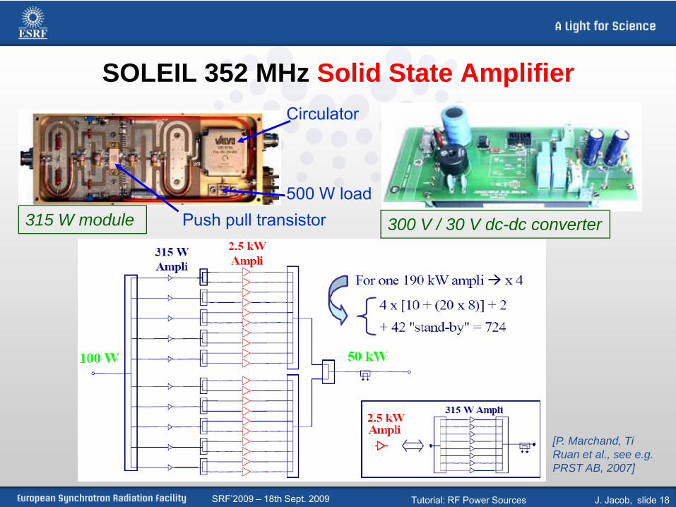
SOLEIL 352 MHz Solid State Amplifier
315 W module 300 V / 30 V dc-dc converter
[P. Marchand, Ti Ruan et al., see e.g. PRST AB, 2007]
Circulator
500 W loadPush pull transistor

SRF’2009 – 18th Sept. 2009 Tutorial: RF Power Sources J. Jacob, slide 19
RF Power Combiners and SplittersPo
wer
Com
bine
rPo
wer
Spl
itter

SRF’2009 – 18th Sept. 2009 Tutorial: RF Power Sources J. Jacob, slide 20
SOLEIL 352 MHz Solid State Amplifier
1 SSA = 4 x 45 kW towers → max: 180 kW
First 2 SSA powering2 SC SOLEIL cavities:
SOLEIL storage ring:• no IOT at 352 MHz,
• no klystron for 160 kW / SC cavity
⇒Development of tailored solid state amplifiers for each of the 4 cavities
• Features confirmed after 3 years of operation of the storage ring
Extreme modularityHigh redundancy: no interruption if some modules fail ⇒ reliable operationNo need for HVNo need for a high power circulatorSimple start up proceduresEasy operation and maintenance

SRF’2009 – 18th Sept. 2009 Tutorial: RF Power Sources J. Jacob, slide 21
Cell 5Cav 1 & 2 Cell 7
Cav 3 & 4
Cell 25Cav 5 & 6
BoosterCav 1 & 2
Storage Ring
Teststand
TRA0
TRA1TRA2
TRA3
Cell 23
Existing Operation at 200 mA
Redundancy in case of any transmitter failure
Suppression of HOM driven Longitudinal Coupled Bunch Instabilities by Cavity Temperature regulation
Current upgrade to 300 mA
No transmitter redundancy
Need LFB to stabilize HOM driven instabilities
Increased voltage to master Robinson Instability
Long term
Only 1 klystron manufacturer left, possible obsolescence
That particular design: stability issues
Upgrade of ESRF 352.2 MHz RF system
Existing ESRF RF system

SRF’2009 – 18th Sept. 2009 Tutorial: RF Power Sources J. Jacob, slide 22
ESRF RF upgrade
• Replacement of 6 five-cell cavities with 18 new HOM damped Cavities for the Storage Ring
• Transmitter upgrade with 150 kW Solid State Amplifiers (SSA):
• SSA highly modular ⇒ redundant ⇒intrinsically reliable
• Good experience at SOLEIL
• 20 dB less phase noise
• No HV
• No X rays
• Easy maintenance
• Likely to become the new standard for high power CW RF applications
• Phase 1 has started: procurement of 7 x 150 kW SSA:
• 4 x 150 kW for the booster RF
• 3 x 150 kW for the new RF in cell 23
• Similar layout as for SOLEIL, but with • Next - 6th generation LDMOS transistors
• 500…700 W, i.e. almost doubled RF power per module
• 2 x 75 kW towers, also almost doubled RF power per tower
• Reduced space requirement
• Status: Order for phase 1 about to be placed

SRF’2009 – 18th Sept. 2009 Tutorial: RF Power Sources J. Jacob, slide 23
Overview of ESRF RF upgrade
Storage RingBooster
Cell 5 Cell 7
Cell 25 Cell 23
RF2
Test Bed
150 kW 150 kW 150 kW 150 kW 150 kW 150 kW 150 kW 150 kW
150 kW 150 kW 150 kW 150 kW 150 kW 150 kW 150 kW 150 kW
150 kW
150 kW
600 kW

SRF’2009 – 18th Sept. 2009 Tutorial: RF Power Sources J. Jacob, slide 24
Summary (1)
1. Clear trend towards compact and modular RF transmitters for frequencies ≤ 1.3 GHz
2. As for recent TV transmitters, IOTs are increasingly selected for accelerators: • High η = 65 … 70 %
• Up to 300 kW at 500 MHz by power combining schemes
• Combiners designed to sustain operation if 1 IOT fails
• Modularity, ease of manipulation: attractive features for modern user facilities, which must achieve high up time with limited manpower
• Intrinsically lower phase noise and high efficiency = major advantage of IOTs over Klystrons for 1.3 GHz cw SC Linacs & ERLs

SRF’2009 – 18th Sept. 2009 Tutorial: RF Power Sources J. Jacob, slide 25
Summary (2)
3. Solid state amplifiers entered field of high power RF generation:• Highly innovative approach → next trend for accelerator
applications ?
• Combining 100’s of 300 to 1000 W RF modules to obtain 100’s of kW total RF power
• Could open the door to highly industrialised mass production of RF power modules
• Extremely modular: probably easy to operate and maintain even for small crews
• Overall reliability and availability could approach 100 %, provided:
Intervention and replacement procedures are well established
Good procurement strategy in place

SRF’2009 – 18th Sept. 2009 Tutorial: RF Power Sources J. Jacob, slide 26
Summary (3)
4. Accelerator applications requiring multi-MW level (mostly the case for pulsed systems)
• Replacement of klystrons with the combined power of tens of IOT’s does not seem attractive in terms of complexity, reliability and costs.
• Still need for classical klystron transmitters
5. Today no alternative to high power klystrons at frequencies above 1.3 GHz
[Thales MBK] 7 beams

SRF’2009 – 18th Sept. 2009 Tutorial: RF Power Sources J. Jacob, slide 27
References[0] J. Jacob, New Developments on RF Power Sources, EPAC’2006, Edinburgh, June 2006[1] Thales, “Diacrode: Principe et performances”, www.thalesgroup.com, data sheets, product information. [2] CPI-EIMAC online documentation, www.cpii.com, data sheet, product information.[3] E2V Technologies, product information.[4] S. Grote, “60 kW CW (500 MHz) with a Standard TV Klystron”, EPAC’92, Berlin, March 1992, p. 1212.[5] A. Beunas et al., “A High Efficiency Multi Beam Klystron for the TESLA Linear Collider”, 5th Modulator-Klystron Workshop for Future Linear Colliders, Geneva,
Apr. 2001[6] A. Balkcum et al., “Design and Operation of a High Power L-Band Multiple Beam Klystron”, PAC’05, Knoxville, May 2005, p. 2170.[7] Y. H. Chin et al., « Development of Toshiba L-Band Multi-Beam Klystron for European XFEL Project”, PAC’05, Knoxville, May 2005, p. 3153.[8] A. Yano, Y. Ohkubo, “Design Consideration to PPM Klystrons for Industrial Linac”, LINAC2002, Gyeongju, 2002, p. 464.[9] K. Takata, “Overview of NLC/JLC Collaboration”, LINAC2002, Gyeongju, 2002, p. 254.[10] see e.g.: G. Geschonke & A. Ghigo, “CTF3 Design Report”, CERN/PS 2002-008(RF), Geneva, May, 2002.[11] A. Zolfghari et al., “Comparison of Klystron and Inductive Output Tubes (IOT) Vacuum-Electron Devices for RF Amplifier Service in Free-Electron Laser”,
EPAC’04, Lucerne, July 2004, p. 1093.[12] P. Marchand et al., “High Power (35 kW and 190 kW) 352 MHz Solid State Amplifiers for the SOLEIL Synchrotron, PAC’05, Knoxville, May 2005, p. 811.[13] M. Gaspar et al., “60 kW Solid-State Booster Amplifier”, 4th CWHAPRF meeting, APS, May 2006.[14] J. Fox et al., “Klystron Linearizer for Use with 1.2 MW 476 MHz Klystrons in PEP-II RF Systems”, PAC’05, Knoxville, May 2005, p. 2660.[15] J. Alex et al., “Inductive Output Tube Based 300 kW RF Amplifier for the Diamond Light Source”, EPAC’04, Lucerne, July 2004, p. 962.[16] M. Jensen et al., “First Results of the IOT Based 300 kW 500 MHz Amplifier for the Diamond Light Source”, PAC’05, Knoxville, May 2005, p. 1883.[17] M. Jensen, “Overview and initial results from Diamond”, 9th ESLS RF meeting, Aarhus, September 2005.[18] M. Jensen et al., “Installation and Commissioning of the High Power, IOT Based 300 kW CW Amplifier at Diamond”, EPAC'2006, Edinburgh, June 2006,
TUPCH157.[19] F. Pérez, “ALBA RF System”, 9th ESLS RF Meeting, Aarhus, Sept. 2005. Also EPAC'2006, Edinburgh, June 2006, TUPCH141.[20] B. Baricevic, “Design of a 150 kW Cavity Combiner (CaCo) for the RF power sources of ALBA synchrotron”, 9th ESLS RF Meeting, Aarhus, Sept. 2005. Also
EPAC'2006, Edinburgh, June 2006, THPCH179.[21] A. Fabris et al., “Elettra RF System Upgrade Project”, EPAC’02, Paris, June 2002, p. 2142.[22] A. Fabris, “Status and Developments of the 500 MHz RF Systems for the ELETTRA Booster and Storage Ring”, 4th CWHAPRF meeting, APS, May 2006.[23] C. Thomas-Madec, “Status of the SOLEIL RF Systems”, 4th CWHAPRF meeting, APS, May 2006.[24] XFEL TDR
… See also other references either as indicated on the slides as well as more recent publications from the authors and labs cited above…