rfid antenna 1 getpdf
TRANSCRIPT

8/6/2019 RFID Antenna 1 GetPDF
http://slidepdf.com/reader/full/rfid-antenna-1-getpdf 1/4
Broadband Circularly Polarized Microstrip Antenna for RFID Reader
Applications
Yan Shan Boo#1, Nasimuddin*2, Z. N. Chen*3, and A. Alphones#4 #
School of EEE, Nanyang Technological University, Singapore*
RF and Optical Department, Institute for Infocomm Research1 Fusionopolis Way, #21-01 Singapore
Abstract — A broadband single-feed compact circularly polarized
stacked microstrip antenna for radio frequency identification
(RFID) reader applications is proposed and investigated. The
proposed antenna achieved a gain of more than 5.0 dBic,impedance bandwidth with VSWR less than 2 and a wide 3-dB
axial-ratio (AR) bandwidth of more than 12% over ultra-high
frequency (UHF) band (840 – 940 MHz). The overall antenna
size is 0.48λo × 0.48λo × 0.0984λo at 900 MHz. The proposed
antenna is attractive for RFID reader applications which require
compact size and good circular polarization operation.
Index terms – Circular polarization, RFID, microstrip
antenna, UHF
I. I NTRODUCTION
RFID technology utilizes the characteristics of microstrip
antennas and is used extensively in service industries,
distribution logistics and even transport systems [1, 2].
However, there is a standard UHF range accepted
internationally for RFID applications and different countriesuses different frequency ranges [3, 4]: 865.5 – 867.6 MHz in
Europe, 920 – 926 MHz in Australia, 866 – 869 MHz, 923 –
925 MHz in Singapore, 902 – 928 MHz in US/Canada, 910 –
914 MHz in Korea and 952 – 955 MHz in Japan. The total
frequency span of UHF band used for RFID systems is 840 -
960 MHz. A RFID reader that is able to accommodate theentire RFID frequency range provides better flexibility and
interoperability between devices and a reader antenna with a
smaller size reduces the manufacturing cost. However, these
two properties are dependent on each other. The drawback to
a reduced antenna size is limited bandwidth and gain. Hence,
it is necessary to make a trade off between size and bandwidth.In this paper, a single-feed compact broadband circularly
polarized stacked microstrip antenna for RFID reader
applications is presented. The main patch is fabricated on
thick FR4 substrate to enhance the axial-ratio (AR) and
impedance bandwidths of the antenna. A broadband circularly
polarized stacked microstrip antenna is designed, fabricatedand tested. The measured and simulated results are in good
agreement. The proposed antenna design and optimization is
carried out with IE3D EM simulator.
II. A NTENNA GEOMETRY AND DESIGN The geometry of the proposed antenna is as shown in Fig. 1.
A coaxial-probe is used as the feeding structure of the antenna.
To achieve a wide bandwidth, the upper patch (114.0 mm ×
104.0 mm) on thin FR4 substrate with foam and the lower
patch (86.0 mm × 77.5 mm) is fabricated on thick FR4
substrate (εr = 4.3, tanδ = 0.02). The patch is fed at an
optimum feed location to radiate wide and good CP waves.The antenna designed dimensions are given in Table I, and all
are in mm.
Fig. 1(a). Cross-section view of the proposed antenna.
978-1-4244-2802-1/09/$25.00 ©2009 IEEE625
Authorized licensed use limited to: Universitas Indonesia. Downloaded on April 08,2010 at 02:53:35 UTC from IEEE Xplore. Restrictions apply.

8/6/2019 RFID Antenna 1 GetPDF
http://slidepdf.com/reader/full/rfid-antenna-1-getpdf 2/4
Table I. Antenna designed dimensions (in mm)
Fig. 1(b). Fabricated prototype antenna.
The challenges of the proposed RFID reader antenna require
good impedance matching, wide axial-ratio bandwidth and
high gain with compact size and low cost. There are many
ways of implementing circular polarization. In this proposed
design, circular polarization is achieved by introducing anoffset feed in the antenna at an angle around of 45º using a
coaxial probe [5]. The exact location of the probe is
determined by varying the probe along an arc to locate the
optimum point between x- y axes.
The coaxial-probe location is first determined as one fourth
of the upper patch length. The coaxial-probe location is then
simulated along the x-axis to obtain the best impedance
matching with the load. Thereafter, the probe location is
simulated along the xy-axis with varying angles to find the
optimum circularly polarized performance [5] at which the
good impedance matching of the antenna within the operating
frequency.
Table II: Effects of the probe location on AR and 3dB AR bandwidth.
The x-coordinate of the probe location is determined as
41.0 mm from the origin. The probe location at 35o
from the
x-axis is chosen as it provided a broader bandwidth compared to the others. The 3-dB AR bandwidth is also wide over the
frequency band from 850 MHz to 950 MHz. The final probe
location (origin at centre of the patch) achieved is at xo =
33.58 mm, and yo = 23.51 mm for wide circular polarization
radiation as shown in Table II.
III. R ESULTS AND DISCUSSIONS
Fig. 2 shows the measured and simulated VSWR with
frequency of the antenna. The measured bandwidth with
VSWR of 2 is around 141 MHz (803 – 944 MHz). The
simulated VSWR bandwidth from IE3D simulator is 138 MHz
(805 – 943 MHz). The measured return loss of the antenna isin good agreement with the return loss results obtained from
the simulation.
0.80 0.85 0.90 0.95 1.001.0
1.5
2.0
2.5
3.0
3.5
4.0
V S W R
Frequency, GHz
Measured
Simulated
Fig. 2. Simulated and measured return loss.
0.80 0.85 0.90 0.95 1.00
0
5
10
15
20
25
30
A x i a l - r a t i o ,
d B
Frequency, GHz
Measured
Simulated
Fig. 3. Simulated and measured axial-ratio at boresight
The AR is measured using spinning linear method where a
rotating linearly polarized transmit horn antenna is used to
measure the CP performance of the antenna. The measured
data is then stored electronically and post-processed to
determine the axial-ratio and gain of the antenna. From Fig. 3,
the measured 3-dB AR bandwidth is more than 12%. The AR
626
Authorized licensed use limited to: Universitas Indonesia. Downloaded on April 08,2010 at 02:53:35 UTC from IEEE Xplore. Restrictions apply.

8/6/2019 RFID Antenna 1 GetPDF
http://slidepdf.com/reader/full/rfid-antenna-1-getpdf 3/4
bandwidth of the antenna is able to cover total UHF RFID
band. However, impedance bandwidth (2.0 VSWR) is not ableto cover total UHF RFID band. The measured axial-ratio is
achieved better than the simulated axial-ratio results from the
frequency range of 843 MHz to 950 MHz. There is a slight
shift in frequency between the measured and simulated results
which could be due to fabrication tolerances.
0.80 0.85 0.90 0.95 1.000
1
2
3
4
5
6
7
8
9
10
G a i n ( d B i c )
Frequency, GHz
Measured
Simulated
Fig. 4. Simulated and measured gain at boresight.
Fig. 4 shows the measured and simulated gain at boresight.
From the results, the measured maximum gain is around 7.2
dBic at 912 MHz. The measured gain is more than 5 dBic
over the frequency range from 840 MHz to 960 MHz. A goodagreement is achieved between measured and simulated gain
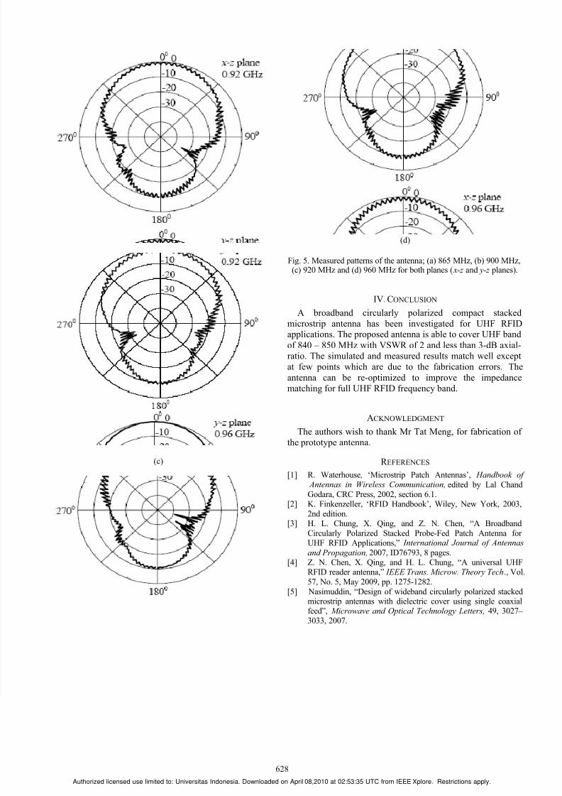
values. The normalized radiation patterns of the antenna at
865 MHz, 900 MHz, 920 MHz and 960 MHz are shown in
Figs. 5(a)-5(d), respectively for both x-z and y-z planes. The
3-dB AR beamwidth is more than 100o
over the 3-dB axial-
ratio bandwidth.
(a)
(b)
627
Authorized licensed use limited to: Universitas Indonesia. Downloaded on April 08,2010 at 02:53:35 UTC from IEEE Xplore. Restrictions apply.
8/6/2019 RFID Antenna 1 GetPDF
http://slidepdf.com/reader/full/rfid-antenna-1-getpdf 4/4
(c)
(d)
Fig. 5. Measured patterns of the antenna; (a) 865 MHz, (b) 900 MHz,(c) 920 MHz and (d) 960 MHz for both planes ( x-z and y-z planes).
IV. CONCLUSION
A broadband circularly polarized compact stacked
microstrip antenna has been investigated for UHF RFIDapplications. The proposed antenna is able to cover UHF band
of 840 – 850 MHz with VSWR of 2 and less than 3-dB axial-
ratio. The simulated and measured results match well except
at few points which are due to the fabrication errors. The
antenna can be re-optimized to improve the impedance
matching for full UHF RFID frequency band.
ACKNOWLEDGMENT The authors wish to thank Mr Tat Meng, for fabrication of
the prototype antenna.
R EFERENCES
[1] R. Waterhouse , ‘Microstrip Patch Antennas’, Handbook of Antennas in Wireless Communication, edited by Lal ChandGodara, CRC Press, 2002, section 6.1.
[2] K. Finkenzeller, ‘RFID Handbook’, Wiley, New York, 2003,
2nd edition.[3] H. L. Chung, X. Qing, and Z. N. Chen, “A Broadband
Circularly Polarized Stacked Probe-Fed Patch Antenna for UHF RFID Applications,” International Journal of Antennas
and Propagation, 2007, ID76793, 8 pages.[4] Z. N. Chen, X. Qing, and H. L. Chung, “A universal UHF
RFID reader antenna,” IEEE Trans. Microw. Theory Tech., Vol.
57, No. 5, May 2009, pp. 1275-1282.
[5] Nasimuddin, “Design of wideband circularly polarized stackedmicrostrip antennas with dielectric cover using single coaxialfeed”, Microwave and Optical Technology Letters, 49, 3027– 3033, 2007.
628
Authorized licensed use limited to: Universitas Indonesia. Downloaded on April 08,2010 at 02:53:35 UTC from IEEE Xplore. Restrictions apply.