rfid-systems - wesco northwest automation | wesco...
TRANSCRIPT

simatic sensors
System Manual Edition 06/2005
RFID-SYSTEMSSIMATIC RF 300


Introduction 1
Safety information 2
System overview 3
RF 300 system planning 4
Readers 5
Transponder/tags 6
Communication modules 7
Accessories 8
Appendix A
SIMATIC
RFID systemsRF 300
System Manual
Edition 05/2005

Safety Guidelines This manual contains notices you have to observe in order to ensure your personal safety, as well as to prevent damage to property. The notices referring to your personal safety are highlighted in the manual by a safety alert symbol, notices referring to property damage only have no safety alert symbol. These notices shown below are graded according to the degree of danger.
Danger
indicates that death or severe personal injury will result if proper precautions are not taken.
Warning
indicates that death or severe personal injury may result if proper precautions are not taken.
Caution
with a safety alert symbol, indicates that minor personal injury can result if proper precautions are not taken.
Caution
without a safety alert symbol, indicates that property damage can result if proper precautions are not taken.
Notice
indicates that an unintended result or situation can occur if the corresponding information is not taken into account.
If more than one degree of danger is present, the warning notice representing the highest degree of danger will be used. A notice warning of injury to persons with a safety alert symbol may also include a warning relating to property damage.
Qualified Personnel The device/system may only be set up and used in conjunction with this documentation. Commissioning and operation of a device/system may only be performed by qualified personnel. Within the context of the safety notes in this documentation qualified persons are defined as persons who are authorized to commission, ground and label devices, systems and circuits in accordance with established safety practices and standards.
Prescribed Usage Note the following:
Warning
This device may only be used for the applications described in the catalog or the technical description and only in connection with devices or components from other manufacturers which have been approved or recommended by Siemens. Correct, reliable operation of the product requires proper transport, storage, positioning and assembly as well as careful operation and maintenance.
Trademarks All names identified by ® are registered trademarks of the Siemens AG. The remaining trademarks in this publication may be trademarks whose use by third parties for their own purposes could violate the rights of the owner.
Copyright Siemens AG . All rights reserved. The distribution and duplication of this document or the utilization and transmission of its contents are not permitted without express written permission. Offenders will be liable for damages. All rights, including rights created by patent grant or registration of a utility model or design, are reserved.
Disclaimer of Liability We have reviewed the contents of this publication to ensure consistency with the hardware and software described. Since variance cannot be precluded entirely, we cannot guarantee full consistency. However, the information in this publication is reviewed regularly and any necessary corrections are included in subsequent editions.
Siemens AG Automation and Drives Postfach 4848, 90327 Nuremberg, Germany
Siemens AG 2005 Technical data subject to change
Siemens Aktiengesellschaft --

RF 300 System Manual, 05/2005, (4)J31069 D0166-U001-A1-7618, -- iii
Table of contents 1 Introduction............................................................................................................................................. 1-1
1.1 Navigating in the system manual ............................................................................................... 1-2
2 Safety information................................................................................................................................... 2-1
3 System overview..................................................................................................................................... 3-1
3.1 RFID systems............................................................................................................................. 3-1
3.2 RF 300 ....................................................................................................................................... 3-2 3.2.1 RF 300 application areas ........................................................................................................... 3-2 3.2.2 RFID components and their function ......................................................................................... 3-3 3.2.3 Technical data............................................................................................................................ 3-4
4 RF 300 system planning ......................................................................................................................... 4-1
4.1 Fundamentals of application planning ....................................................................................... 4-1 4.1.1 Transmission window and read/write distance .......................................................................... 4-2 4.1.2 Width of the transmission window.............................................................................................. 4-3 4.1.3 Impact of secondary fields ......................................................................................................... 4-3 4.1.4 Permissible directions of motion of the transponder.................................................................. 4-4 4.1.5 Operation in static and dynamic mode ...................................................................................... 4-5 4.1.6 Dwell time of the transponder .................................................................................................... 4-6 4.1.7 Communication between communication module, reader and transponder ............................. 4-7 4.1.8 Calculation example................................................................................................................... 4-9
4.2 Field data of transponders and readers................................................................................... 4-12
4.3 Impact of the data volume on the transponder speed with RF 310-R (IQ-Sense) .................. 4-13
4.4 Installation guidelines............................................................................................................... 4-14 4.4.1 Overview .................................................................................................................................. 4-14 4.4.2 Reduction of interference due to metal.................................................................................... 4-15 4.4.3 Effects of metal on different transponders and readers........................................................... 4-18 4.4.4 Impact on the transmission window by metal .......................................................................... 4-19
4.5 Chemical resistance of the transponders ................................................................................ 4-21
4.6 EMC Guidelines ....................................................................................................................... 4-26 4.6.1 Overview .................................................................................................................................. 4-26 4.6.2 Definition .................................................................................................................................. 4-27 4.6.3 Basic rules................................................................................................................................ 4-28 4.6.4 Propagation of electromagnetic interference........................................................................... 4-29 4.6.5 Cabinet configuration ............................................................................................................... 4-32 4.6.6 Prevention of interference sources .......................................................................................... 4-35 4.6.7 Equipotential bonding .............................................................................................................. 4-36 4.6.8 Cable shielding......................................................................................................................... 4-37
Table of contents
RF 300 iv System Manual, 05/2005, (4)J31069 D0166-U001-A1-7618, --
5 Readers .................................................................................................................................................. 5-1
5.1 RF 310-R.................................................................................................................................... 5-2 5.1.1 Features ..................................................................................................................................... 5-2 5.1.2 Indicators.................................................................................................................................... 5-2 5.1.3 Transmission window................................................................................................................. 5-3 5.1.4 Metal-free area........................................................................................................................... 5-3 5.1.5 Minimum distance between several RF 310-R units ................................................................. 5-4 5.1.6 RF 310-R field data .................................................................................................................... 5-4 5.1.7 Pin assignment of the IQ-Sense interface ................................................................................. 5-5 5.1.8 Cable and connector pin assignment......................................................................................... 5-5 5.1.9 Technical data of the RF 310-R ................................................................................................. 5-6 5.1.10 FCC information ......................................................................................................................... 5-7 5.1.11 RF 310-R ordering data ............................................................................................................. 5-7 5.1.12 Dimension drawing..................................................................................................................... 5-8
6 Transponder/tags.................................................................................................................................... 6-1
6.1 RF 320-T .................................................................................................................................... 6-2 6.1.1 Features ..................................................................................................................................... 6-2 6.1.2 Metal-free area........................................................................................................................... 6-3 6.1.3 Field data.................................................................................................................................... 6-4 6.1.4 Technical data............................................................................................................................ 6-5 6.1.5 Ordering data ............................................................................................................................. 6-6 6.1.6 Dimension drawing..................................................................................................................... 6-6
6.2 RF 340-T .................................................................................................................................... 6-7 6.2.1 Features ..................................................................................................................................... 6-7 6.2.2 Metal-free area........................................................................................................................... 6-8 6.2.3 Field data.................................................................................................................................... 6-9 6.2.4 Technical data.......................................................................................................................... 6-10 6.2.5 Ordering data ........................................................................................................................... 6-11 6.2.6 Dimension drawing................................................................................................................... 6-11
7 Communication modules ........................................................................................................................ 7-1
7.1 8xIQ-Sense ................................................................................................................................ 7-2 7.1.1 Features ..................................................................................................................................... 7-2 7.1.2 Indicators.................................................................................................................................... 7-3 7.1.3 Configuration.............................................................................................................................. 7-4 7.1.4 Addressing ................................................................................................................................. 7-5 7.1.5 Technical data............................................................................................................................ 7-7 7.1.6 Ordering data ............................................................................................................................. 7-7
8 Accessories ............................................................................................................................................ 8-1
8.1 MOBY software .......................................................................................................................... 8-1
A Appendix.................................................................................................................................................A-1
A.1 Certificates and approvals..........................................................................................................A-1
A.2 Service and support ...................................................................................................................A-3
A.3 Contact partners.........................................................................................................................A-3
A.4 Application consulting ................................................................................................................A-4
A.5 Training ......................................................................................................................................A-4
List of abbreviations.................................................................................................................... Glossary-1
Glossary ..................................................................................................................................... Glossary-1
Index

Table of contents
RF 300 System Manual, 05/2005, (4)J31069 D0166-U001-A1-7618, -- v
Tables
Table 4-1 Reduction of field data by metal (in %): Transponder and RF 310-R...................................... 4-20 Table 4-2 Interference sources: origin and effect .................................................................................... 4-30 Table 4-3 Causes of coupling paths......................................................................................................... 4-31 Table 5-1 RF 310-R indicators ................................................................................................................... 5-2 Table 5-2 RF 310-R pin assignment .......................................................................................................... 5-5 Table 5-3 Technical data of the RF 310-R................................................................................................. 5-6 Table 6-1 Field data for transponder RF 320-T to reader RF 310-R ......................................................... 6-4 Table 6-2 Field data for transponder RF 320-T to RF 320-T ..................................................................... 6-4 Table 6-3 Technical data of the RF 320-T ................................................................................................. 6-5 Table 6-4 Field data for transponder RF 340-T to reader RF 310-R ......................................................... 6-9 Table 6-5 Transponder RF 340-T to transponder RF 340-T...................................................................... 6-9 Table 6-6 Technical data of the RF 340-T ............................................................................................... 6-10

Table of contents
RF 300 vi System Manual, 05/2005, (4)J31069 D0166-U001-A1-7618, --

RF 300 System Manual, 05/2005, (4)J31069 D0166-U001-A1-7618, -- 1-1
Introduction 1Purpose of this document
This system manual contains all the information needed to plan and configure the system.
It is intended both for programming and testing/debugging personnel who commission the system themselves and connect it with other units (automation systems, further programming devices), as well as for service and maintenance personnel who install expansions or carry out fault/error analyses.
Scope of validity of this document This documentation is valid for all supplied variations of the SIMATIC RF 300 system and describes the state of delivery as of May 2005.
Conventions The following terms/abbreviations are used synonymously in this document:
• Reader, read/write device, SLG
• Tag, transponder, mobile data memory, MDS
• Communication module, interface module, ASM
History Previous editions of these operating instructions:
Edition Remarks 05/2005 First Edition
Declaration of conformity The EC declaration of conformity and the corresponding documentation are made available to authorities in accordance with the EC directives stated above. Your sales representative can provide these on request.
Observance of installation guidelines The installation guidelines and safety instructions given in this documentation must be followed during commissioning and operation.

Introduction 1.1 Navigating in the system manual
RF 300 1-2 System Manual, 05/2005, (4)J31069 D0166-U001-A1-7618, --
1.1 Navigating in the system manual Structure of contents Contents
Contents Organization of the documentation, including the index of pages and chapters Introduction Purpose, layout and description of the important topics. Safety information Refers to all the valid technical safety aspects which have to be adhered to while installing,
commissioning and operating the product/system and with reference to statutory regulations.
System overview Overview of all RF identification systems, system overview of SIMATIC RF 300 RFID system planning Information about possible applications of SIMATIC RF 300, support for application
planning, tools for finding suitable SIMATIC RD 300 components. Readers Description of readers which can be used for SIMATIC RF 300 Transponders Description of transponders which can be used for SIMATIC RF 300 Communication modules Description of communication modules used for SIMATIC RF 300 Accessories Products available in addition to SIMATIC RF 300 Appendix Service and support, contact partners, training centers Error messages Overview of error messages List of abbreviations List of all abbreviations used in the document
RF 300 System Manual, 05/2005, (4)J31069 D0166-U001-A1-7618, -- 2-1
Safety information 2
Caution
Please observe the safety instructions on the back cover of this documentation.
SIMATIC RFID products comply with the salient safety specifications to IEC, VDE, EN, UL and CSA. If you have questions about the admissibility of the installation in the designated environment, please contact your service representative.
Caution
Alterations to the devices are not permitted.
Failure to observe this requirement shall constitute a revocation of the radio equipment approval, CE approval and manufacturer's warranty.
Repairs Repairs may only be carried out by authorized qualified personnel.
Warning
Unauthorized opening of and improper repairs to the device may result in substantial damage to equipment or risk of personal injury to the user.

Safety information
RF 300 2-2 System Manual, 05/2005, (4)J31069 D0166-U001-A1-7618, --
System expansion Only install system expansion devices designed for this device. If you install other upgrades, you may damage the system or violate the safety requirements and regulations for radio frequency interference suppression. Contact your technical support team or your sales outlet to find out which system upgrades are suitable for installation.
Caution
If you cause system defects by installing or exchanging system expansion devices, the warranty becomes void.
RF 300 System Manual, 05/2005, (4)J31069 D0166-U001-A1-7618, -- 3-1
System overview 33.1 RFID systems
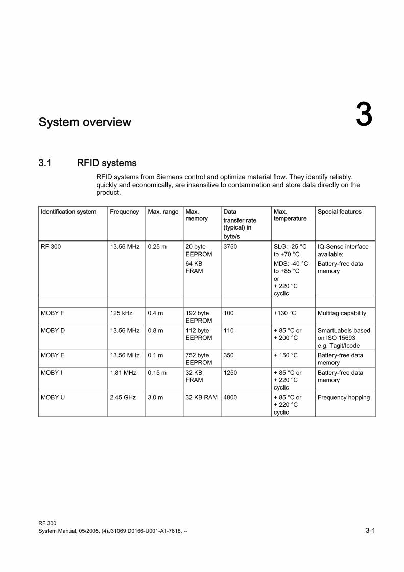
RFID systems from Siemens control and optimize material flow. They identify reliably, quickly and economically, are insensitive to contamination and store data directly on the product.
Identification system Frequency Max. range Max.
memory Data transfer rate (typical) in byte/s
Max. temperature
Special features
RF 300 13.56 MHz 0.25 m 20 byte EEPROM 64 KB FRAM
3750 SLG: -25 °C to +70 °C MDS: -40 °C to +85 °C or + 220 °C cyclic
IQ-Sense interface available; Battery-free data memory
MOBY F 125 kHz 0.4 m 192 byte
EEPROM 100 +130 °C Multitag capability
MOBY D 13.56 MHz 0.8 m 112 byte EEPROM
110 + 85 °C or + 200 °C
SmartLabels based on ISO 15693 e.g. Tagit/Icode
MOBY E 13.56 MHz 0.1 m 752 byte EEPROM
350 + 150 °C Battery-free data memory
MOBY I 1.81 MHz 0.15 m 32 KB FRAM
1250 + 85 °C or + 220 °C cyclic
Battery-free data memory
MOBY U 2.45 GHz 3.0 m 32 KB RAM 4800 + 85 °C or + 220 °C cyclic
Frequency hopping

System overview 3.2 RF 300
RF 300 3-2 System Manual, 05/2005, (4)J31069 D0166-U001-A1-7618, --
3.2 RF 300 SIMATIC RF 300 is an inductive identification system specially designed for use in industrial production for the control and optimization of material flow. Thanks to its compact components it is particularly suited to small assembly lines and conveyor systems with restricted space for installation. The rugged components feature an attractive price/performance ratio.
3.2.1 RF 300 application areas SIMATIC RF 300 is used primarily for contactless identification of containers, pallets and workpiece carriers in a closed production loop, i.e. the data carriers (transponders) remain in the production chain and are not shipped out with the products. Thanks to the compact enclosure dimensions of both the transponders and readers, SIMATIC RF 300 is particularly suitable for (small) assembly lines where space is at a premium.
The main application areas of SIMATIC RF 300 are:
• Assembly and handling systems, assembly lines (identification of workpiece carriers)
• Production logistics (material flow control, identification of containers and other vessels)
• Parts identification (e.g. transponder is attached to product/pallet).
• Conveyor systems

System overview 3.2 RF 300
RF 300 System Manual, 05/2005, (4)J31069 D0166-U001-A1-7618, -- 3-3
3.2.2 RFID components and their function
RF 300 system components
Communication modules
A communication module (interface module) is used to integrate the RF identification system in PLC/automation systems. In the case of SIMATIC RF 300, the reader is connected to an S7 automation system either via the 8xIQ-Sense module or an equivalent MOBY interface module (e.g. ASM 475).
Readers The reader ensures inductive communication, supplies power to the transponders, and handles the connection to the various PLCs (e.g. SIMATIC S7).
Transponders Transponders (mobile data memories) are used, for example, in place of barcodes and can contain all product-specific data in addition to the product number.

System overview 3.2 RF 300
RF 300 3-4 System Manual, 05/2005, (4)J31069 D0166-U001-A1-7618, --
3.2.3 Technical data
RFID system RF 300
Type Inductive identification system for industrial applications
Transmission frequency data/energy 13.56 MHz Memory capacity 20 bytes up to 64 KB user memory (r/w)
4 bytes fixed code as serial number (ro) Memory type EEPROM / FRAM Write cycles EEPROM: > 100 000
FRAM: Unlimited Read cycles Unlimited Data management Byte-oriented access Data transfer rate Transponder-Reader 3 KB/s Read/write distance (system limit; depends on reader and transponder)
Up to 250 mm
Operating temperature Reader: -25°C to +70°C Transponder: -40°C to +85°C and up to +220°C cyclic
Degree of protection Reader: IP 65 Transponder: > IP 67
Can be connected to SIMATIC S7-300, Profibus DP V1, PC, third-party PLC
Special features High noise immunity Compact components Extensive diagnostic options A reader with IQ-Sense interface
Approvals ETS 300 330 (Europe) FCC Part 15 (USA), UL/CSA CE
RF 300 System Manual, 05/2005, (4)J31069 D0166-U001-A1-7618, -- 4-1
RF 300 system planning 44.1 Fundamentals of application planning
Assess your application according to the following criteria, in order to choose the right SIMATIC RF 300 components:
• Transmission distance (read/write distance)
• Tracking tolerances
• Static or dynamic data transfer
• Data volume to be transferred
• Speed in case of dynamic transfer
• Metal-free rooms for transponders and readers
• Ambient conditions such as relative humidity, temperature, chemical impacts, etc.

RF 300 system planning 4.1 Fundamentals of application planning
RF 300 4-2 System Manual, 05/2005, (4)J31069 D0166-U001-A1-7618, --
4.1.1 Transmission window and read/write distance The reader generates an inductive alternating field. The field is strongest near to the reader. The strength of the field decreases in proportion to the distance from the reader. The distribution of the field depends on the structure and geometry of the antennas in the reader and transponder.
A prerequisite for the function of the transponder is a minimum field strength at the transponder achieved at a distance Sg from the reader. The picture below shows the transmission window between transponder and reader:
Sa Operating distance between transponder and reader Sg Limit distance (maximum clear distance between upper surface of the reader and the
transponder, at which the transmission can still function under normal conditions) L Length of a transmission window
The length Ld is valid for the calculation. At Sa,min, the field length increases from Ld to Lmax. SP Intersection of the axes of symmetry of the transponder
The active field for the transponder consists of a circle (cf. plan view).
The transponder can be used as soon as the intersection (SP) of the transponder enters the circle of the transmission window.

RF 300 system planning 4.1 Fundamentals of application planning
RF 300 System Manual, 05/2005, (4)J31069 D0166-U001-A1-7618, -- 4-3
From the diagram above, it can also be seen that operation is possible within the area between Sa and Sg. The active operating area reduces as the distance increases, and shrinks to a single point at distance Sg. Only static mode should thus be used in the area between Sa and Sg.
4.1.2 Width of the transmission window
Determining the width of the transmission window The following approximation formula can be used for practical applications:
0,4B L= ⋅
Figure 4-1 Formula: Width of the transmission window
B: Width of the transmission window L: Length of the transmission window
Tracking tolerances The width of the transmission window (B) is particularly important for the mechanical tracking tolerance. The formula for the dwell time is valid without restriction when B is observed.
4.1.3 Impact of secondary fields Secondary fields in the range from 0 to 20 mm always exist. They should only be applied during planning in exceptional cases, however, since the read/write distances are very limited. Exact details of the secondary field geometry cannot be given, since these values depend heavily on the operating distance and the application.

RF 300 system planning 4.1 Fundamentals of application planning
RF 300 4-4 System Manual, 05/2005, (4)J31069 D0166-U001-A1-7618, --
4.1.4 Permissible directions of motion of the transponder
Active area and direction of motion of the transponder The transponder and reader have no polarization axis, i.e. the transponder can come in from any direction, be placed at any position, and cross the transmission window. The figure below shows the active area for various directions of transponder motion:
Figure 4-2 Active areas of the transponder for different directions of transponder motion

RF 300 system planning 4.1 Fundamentals of application planning
RF 300 System Manual, 05/2005, (4)J31069 D0166-U001-A1-7618, -- 4-5
4.1.5 Operation in static and dynamic mode
Operation in static mode If working in static mode, the transponder can be operated up to the limit distance (Sg). The transponder must then be positioned exactly over the reader:
Figure 4-3 Operation in static mode
Operation in dynamic mode When working in dynamic mode, the transponder moves past the reader. The transponder can be used as soon as the intersection (SP) of the transponder enters the circle of the transmission window.
Figure 4-4 Operation in dynamic mode

RF 300 system planning 4.1 Fundamentals of application planning
RF 300 4-6 System Manual, 05/2005, (4)J31069 D0166-U001-A1-7618, --
4.1.6 Dwell time of the transponder The dwell time is the time in which the transponder dwells within the transmission window of a reader. The reader can exchange data with the transponder during this time.
The dwell time is calculated thus:
0,8[ ]
[ / ]TPDR
KL mtv m s⋅
=
tV: Dwell time of the transponder L: Length of the transmission window vTPDR: Speed of the transponder (TPDR) in dynamic mode 0,8: Constant factor used to compensate for temperature impacts and production tolerances
The dwell time can be of any duration in static mode. The dwell time must be sufficiently long to allow communication with the transponder.
The dwell time is defined by the system environment in dynamic mode. The volume of data to be transferred must be matched to the dwell time or vice versa.
In general:
Kvt t≥
tV:: Dwell time of the data memory within the field of the reader tK: Communication time between transponder and communication module

RF 300 system planning 4.1 Fundamentals of application planning
RF 300 System Manual, 05/2005, (4)J31069 D0166-U001-A1-7618, -- 4-7
4.1.7 Communication between communication module, reader and transponder
Communication with RF 310-R Communication between the communication module (IQ Sense), RF 310-R reader and transponders takes place in fixed telegram cycles. 3 cycles of approximately 3 ms are always needed for the transfer of a read or write command. 1 or 2 bytes of user data can be transferred with each of these commands. The acknowledgement transfer (status or read data) takes place in 3 further cycles. Approximately 18 ms are thus needed for a complete command acknowledgement sequence with up to 2 bytes of user data. The transponder must be present within the field of the reader.
Calculation of the communication time for interference-free transfer
K Wortt K t n= + ⋅
Calculation of the maximum amount of user data
max
Wort
vt Knt−
=
tK Communication time between communication module, RF 310-R (IQ-Sense) reader and
transponder tV Dwell time n Amount of user data in words (2 bytes) nmax Max. amount of user data in words (2 bytes) in dynamic mode tWord Transfer time for 1 word (2 bytes) K Constant (internal system time) This contains the time for power buildup on the transponder
and for command transfer
Note
If only 1 byte of user data is transferred, you still need to allow the time for 1 word.

RF 300 system planning 4.1 Fundamentals of application planning
RF 300 4-8 System Manual, 05/2005, (4)J31069 D0166-U001-A1-7618, --
Time constants K and tWord
K (ms) tWord (ms) Command 9 18 Read 9 27 Write (EEPROM area) 9 18 Write (FRAM area)
The table of time constants applies to every command. If a user command consists of several subcommands, the above tK formula must be applied to each subcommand.

RF 300 system planning 4.1 Fundamentals of application planning
RF 300 System Manual, 05/2005, (4)J31069 D0166-U001-A1-7618, -- 4-9
4.1.8 Calculation example A transport system moves pallets with transponders at a maximum velocity of VTPDR = 0.14 m/s. The following RFID components were chosen:
• 8xIQ-Sense module
• RF 310-R reader
• RF 340-T transponder
Task specification a) The designer of the plant is to be given mechanical specifications.
b) The programmer should be given the maximum number of words in dynamic mode.
Refer to the tables in the "Field data of transponders and readers" section for the technical data.

RF 300 system planning 4.1 Fundamentals of application planning
RF 300 4-10 System Manual, 05/2005, (4)J31069 D0166-U001-A1-7618, --
Determine tolerance of pallet transport height
Figure 4-5 Tolerance of pallet transport height
Determine tolerance of pallet side transport
Figure 4-6 Tolerance of pallet side transport
Minimum distance from reader to reader Refer to the field data of the reader for this value.
Minimum distance from transponder to transponder Refer to the field data of the transponder for this value.

RF 300 system planning 4.1 Fundamentals of application planning
RF 300 System Manual, 05/2005, (4)J31069 D0166-U001-A1-7618, -- 4-11
Calculation of the maximum amount of user data in dynamic mode Step Formula/calculation 1. Calculate dwell time of the
transponder Refer to the "Field data of all transponders and readers" table for value L. Value VTPDR = 0.14m/s
0,8 0,04 0,80,228 228
0,14 /TPDR
vL mt s msv m s⋅ ⋅
= = = =
2. Calculate maximum user data (nmax)
for reading Take value tv from Step 1. Take values K and t Word from Table "Time constants K and t Word".
max228 9
12,17 1218Wort
vt K ms ms n Wordst ms− −
= = ⇒ =
3. Calculate maximum user data (nmax)
for writing (FRAM area)
Take value tv from Step 1. Take values K and t Word from Table "Time constants K and t Word".
max228 9
12,17 1218Wort
vt K ms ms n Wortet ms− −
= = ⇒ =
Result A maximum of 12 words can be read or written when passing the transponder.

RF 300 system planning 4.2 Field data of transponders and readers
RF 300 4-12 System Manual, 05/2005, (4)J31069 D0166-U001-A1-7618, --
4.2 Field data of transponders and readers The following table shows the field data for all SIMATIC RF 300 components of transponders and readers. It facilitates the correct selection of a transponder and reader.
All the technical data listed are typical data and are applicable for an ambient temperature of between 0 C and +50 °C, a supply voltage of between 22 V and 27 V DC and a metal-free environment. Tolerances of ±20 % are admissible due to production or temperature conditions.
If the entire voltage range at the reader of 20 V DC to 30 V DC and/or the entire temperature range of transponders and readers is used, the field data are subject to further tolerances.
Field data of all transponders and readers without interference from metal
RF 310-R reader RF 320-T transponder RF 340-T transponder Length of the transmission window in mm (L) 30 mm 40 mm Width of the transmission window in mm (W) 12 mm 16 mm Working distance in mm (Sa) 0-12 mm 0-20 mm Limit distance in mm (Sg) 18 mm 30 mm
• A maximum mean deviation of ±2 mm is possible in static mode (without affecting the field data)
• This is reduced by approx. 15 % if the transponder enters the transmission window laterally (see also "Transmission window" figure)
Minimum distance from transponder to transponder
Readers RF 320-T transponder RF 340-T transponder
RF 310-R > 100 mm 400 mm
Minimum distance from reader to reader The minimum distance from RF 310-R to RF 310-R must be at least 400 mm.
Notice
Adherence to the values specified in the "Minimum distance from reader to reader" table is essential. The inductive fields may be affected if the distance is smaller. In this case, the data transfer time would increase unpredictably or a command would be aborted with an error.

RF 300 system planning 4.3 Impact of the data volume on the transponder speed with RF 310-R (IQ-Sense)
RF 300 System Manual, 05/2005, (4)J31069 D0166-U001-A1-7618, -- 4-13
4.3 Impact of the data volume on the transponder speed with RF 310-R (IQ-Sense)
The curves shown here show the relationship between the speed of the RF 320 and RF 340 transponders and the volume of data transferred.
Figure 4-7 Relationship between speed and data volume when using the RF 310-R (IQ-Sense)

RF 300 system planning 4.4 Installation guidelines
RF 300 4-14 System Manual, 05/2005, (4)J31069 D0166-U001-A1-7618, --
4.4 Installation guidelines
4.4.1 Overview The transponder and reader are inductive devices. Any type of metal, in particular iron and ferromagnetic materials, in the vicinity of these devices will affect their operation. Some points need to be considered during planning and installation if the values described in the "Field data" section are to retain their validity:
• Minimum distance between two readers
• Minimum distance between two adjacent data memories
• Metal-free area for flush-mounting of readers and transponders in metal
• Mounting of several readers on metal frames or racks
The following sections describe the impact on the operation of the identification system when mounted in the vicinity of metal.

RF 300 system planning 4.4 Installation guidelines
RF 300 System Manual, 05/2005, (4)J31069 D0166-U001-A1-7618, -- 4-15
4.4.2 Reduction of interference due to metal
Interference due to metal rack Problem
A metal rack is located above the transmission window of the reader. This affects the entire field. In particular, the transmission window between reader and transponder is reduced.
Remedy:
The transmission window is no longer affected if the transponder is mounted differently.

RF 300 system planning 4.4 Installation guidelines
RF 300 4-16 System Manual, 05/2005, (4)J31069 D0166-U001-A1-7618, --
Flush-mounting Flush-mounting of transponders and readers Problem
Flush-mounting of transponders and readers is possible in principle. However, the size of the transmission window is significantly reduced. The following measures can be used to counteract the reduction of the window:
Remedy:
Enlargement of the non-metallic spacer below the transponder and/or reader. The transponder and/or reader are 10 to 20 mm higher than the metal surround. (The value x ≥ 100 mm is valid e.g. for RF 310-R. It indicates that the reader is no longer affected significantly by the metal at a distance of x ≥ 100 mm.) Remedy:
Increase the non-metallic distance a, b. The following rule of thumb can be used: • Increase a, b by a factor of 2 to 3
over the values specified for metal-free areas
• Increasing a, b has a greater effect for readers or transponders with a large limit distance than for readers or transponders with a small limit distance.

RF 300 system planning 4.4 Installation guidelines
RF 300 System Manual, 05/2005, (4)J31069 D0166-U001-A1-7618, -- 4-17
Mounting of several readers on metal frames or racks Any reader mounted on metal couples part of the field to the metal frame. There is normally no interaction as long as the minimum distance D and metal-free areas a, b are maintained. However, interaction may take place if an iron frame is positioned unfavorably. Longer data transfer times or sporadic error messages at the communication module are the result.
Mounting of several readers on metal racks Problem: Interaction between readers
Remedy
Increase the distance D between the two readers.
Remedy
Introduce one or more iron struts in order to short-circuit the stray fields.
Remedy
Insert a non-metallic spacer of 20 to 40 millimeter thickness between the reader and the iron frame. This will significantly reduce the induction of stray fields on the rack:

RF 300 system planning 4.4 Installation guidelines
RF 300 4-18 System Manual, 05/2005, (4)J31069 D0166-U001-A1-7618, --
4.4.3 Effects of metal on different transponders and readers
Mounting different transponders on metal or flush-mounting Not all transponders can be mounted directly on metal. For more information, please refer to the descriptions of the individual transponders in the relevant sections.
The following section illustrates various possibilities for mounting, allowing for the effect of metal on the particular transponder.
Transponders which can be mounted directly on metal Any transponder whose operation is not affected by direct contact with metal can be mounted directly on metal.
Mounting of a transponder directly on metal
Flush-mounting of a transponder in metal (a, b = required distance from metal)

RF 300 system planning 4.4 Installation guidelines
RF 300 System Manual, 05/2005, (4)J31069 D0166-U001-A1-7618, -- 4-19
Transponders which cannot be mounted directly on metal Any transponder whose operation is interrupted by direct contact with metal cannot be mounted directly on metal. The applicable minimum distance to metal must be maintained for the relevant transponder.
Mounting of a transponder on metal with a non-metallic spacer
If the minimum guide values (a, h) are not observed, a significant reduction of the field data results. It is possible to mount the transponder with metal screws (M4 countersunk head screws). This has no tangible impact on the range.
4.4.4 Impact on the transmission window by metal In general, the following points should be considered when mounting RFID components:
• Direct mounting on metal is allowed only in the case of specially approved transponders.
• Flush-mounting of the components in metal reduces the field data; a test is recommended in critical applications.
• When working inside the transmission window, it should be ensured that no metal rail (or similar part) intersects the transmission field. The metal rail would affect the field data.

RF 300 system planning 4.4 Installation guidelines
RF 300 4-20 System Manual, 05/2005, (4)J31069 D0166-U001-A1-7618, --
The impact of metal on the field data (Sg, Sa, L, B) is shown in tabular and graphical format in this section. The values in the table describe the reduction of the field data in % with reference to non-metal (100 % means no impact).
Reduction of field data: Transponder and Reader RF 310-R
Table 4-1 Reduction of field data by metal (in %): Transponder and RF 310-R
Transponder Reader RF 310-R
without metal
on metal flush-mounted in metal (20 mm surround)
RF 320-T Transponder without metal 100 95 80 Transponder on metal, distance 20 mm
100 80 70
Flush-mounted in metal 80 70 60 RF 340-T Transponder without metal 100 95 80 Transponder on metal, distance 20 mm
100 95 80
Flush-mounted in metal distance 20 mm/ 20 mm surround
90 85 70
RF 300 system planning 4.5 Chemical resistance of the transponders
RF 300 System Manual, 05/2005, (4)J31069 D0166-U001-A1-7618, -- 4-21
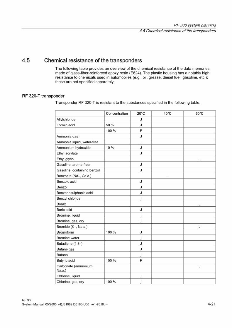
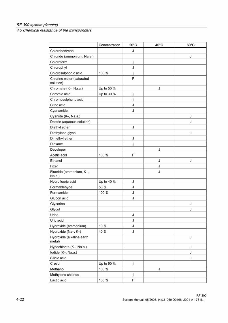
4.5 Chemical resistance of the transponders The following table provides an overview of the chemical resistance of the data memories made of glass-fiber-reinforced epoxy resin (E624). The plastic housing has a notably high resistance to chemicals used in automobiles (e.g.: oil, grease, diesel fuel, gasoline, etc,); these are not specified separately.
RF 320-T transponder Transponder RF 320-T is resistant to the substances specified in the following table.
Concentration 20°C 40°C 60°C Allylchloride J Formic acid 50 % J 100 % F Ammonia gas J Ammonia liquid, water-free j Ammonium hydroxide 10 % J Ethyl acrylate J Ethyl glycol J Gasoline, aroma-free J Gasoline, containing benzol J Benzoate (Na–, Ca.a.) J Benzoic acid J Benzol J Benzenesulphonic acid J Benzyl chloride j Borax J Boric acid J Bromine, liquid j Bromine, gas, dry j Bromide (K–, Na.a.) J Bromoform 100 % J Bromine water j Butadiene (1,3–) J Butane gas J Butanol j Butyric acid 100 % F Carbonate (ammonium, Na.a.)
J
Chlorine, liquid j Chlorine, gas, dry 100 % j
RF 300 system planning 4.5 Chemical resistance of the transponders
RF 300 4-22 System Manual, 05/2005, (4)J31069 D0166-U001-A1-7618, --
Concentration 20°C 40°C 60°C Chlorobenzene J Chloride (ammonium, Na.a.) J Chloroform j Chlorophyl J Chlorosulphonic acid 100 % j Chlorine water (saturated solution)
F
Chromate (K–, Na.a.) Up to 50 % J Chromic acid Up to 30 % j Chromosulphuric acid j Citric acid J Cyanamide J Cyanide (K–, Na.a.) J Dextrin (aqueous solution) J Diethyl ether J Diethylene glycol J Dimethyl ether J Dioxane j Developer J Acetic acid 100 % F Ethanol J J Fixer J Fluoride (ammonium, K–, Na.a.)
J
Hydrofluoric acid Up to 40 % J Formaldehyde 50 % J Formamide 100 % J Glucon acid J Glycerine J Glycol J Urine J Uric acid J Hydroxide (ammonium) 10 % J Hydroxide (Na–, K–) 40 % J Hydroxide (alkaline earth metal)
J
Hypochlorite (K–, Na.a.) J Iodide (K–, Na.a.) J Silicic acid J Cresol Up to 90 % j Methanol 100 % J Methylene chloride j Lactic acid 100 % F

RF 300 system planning 4.5 Chemical resistance of the transponders
RF 300 System Manual, 05/2005, (4)J31069 D0166-U001-A1-7618, -- 4-23
Concentration 20°C 40°C 60°C Mineral oils J Nitrate (ammonium, K.a.) J Nitroglycerine j Oxalic acid J Phenol 1 % J Phosphate (ammonium, Na.a.)
J
Phosphoric acid 50 % J 85 % J Propanol J Nitric acid 25 % j Hydrochloric acid 10 % j Brine j Sulphur dioxide 100 % F Carbon disulfide 100 % j Sulphuric acid 40 % j Sulphurous acid F Soap solution J Sulfate (ammonium, Na.a.) J Sulfite (ammonium, Na.a.) j Tar, aroma-free J Turpentine J Trichloroethylene j Hydrogen peroxide 30 % J Tartaric acid J

RF 300 system planning 4.5 Chemical resistance of the transponders
RF 300 4-24 System Manual, 05/2005, (4)J31069 D0166-U001-A1-7618, --
RF 340-T transponder The following table gives an overview of the chemical composition of the data memories made from polyamide 12. The plastic housing has a notably high resistance to chemicals used in automobiles (e.g.: oil, grease, diesel fuel, gasoline, etc,); these are not specified separately.
Concentration 20°C 60 °C Battery acid 30 F j Ammonia gas J J Ammonia, w. conc. J J 10 J J Benzol J Y Bleach solution (12.5% effective chlorine) F j Butane, gas, liquid J J Butyl acetate (acetic acid butyl ester) J J n(n) J Y Calcium chloride, w. J Y Calcium nitrate, w. c.s. J Y Chlorine j j Chrome baths, tech. j j Iron salts, w. c.s. J J Acetic acid, w. 50 j j Ethyl alcohol, w. undenaturated 96 J Y 50 J J Formaldehyde, w. 30 Y j 10 J Y Formalin Y j Glycerine J J Isopropanol J Y Potassium hydroxide, w. 50 J J Lysol F j Magnesium salts, w. c.s. J J Methyl alcohol, w. 50 J J Lactic acid, w. 50 F j 10 Y F Sodium carbonate, w. (soda) c.s. J J Sodium chloride, w. c.s. J J Sodium hydroxide J J Nickel salts, w. c.s. J J Nitrobenzol Y F Phosphoric acid 10 f V Propane J J Mercury J J Nitric acid 10 f j

RF 300 system planning 4.5 Chemical resistance of the transponders
RF 300 System Manual, 05/2005, (4)J31069 D0166-U001-A1-7618, -- 4-25
Concentration 20°C 60 °C Hydrochloric acid 10 f j Sulphur dioxide Low J J Sulphuric acid 25 F j 10 Y j Hydrogen sulphide Low J J Carbon tetrachloride J J Toluene J Y Detergent High J J Plasticizer J J
Abbreviations
J Resistant Y Virtually resistant F Partially resistant f Less resistant j Not resistant w. Aqueous solution c.s. Cold saturated

RF 300 system planning 4.6 EMC Guidelines
RF 300 4-26 System Manual, 05/2005, (4)J31069 D0166-U001-A1-7618, --
4.6 EMC Guidelines
4.6.1 Overview These EMC Guidelines answer the following questions:
• Why are EMC guidelines necessary?
• What types of external interference have an impact on the control system?
• How can interference be prevented?
• How can interference be eliminated?
• Which standards relate to EMC?
• Examples of interference-free plant design
The description is intended for "qualified personnel":
• Project engineers and planners who plan system configurations with RFID modules and have to observe the necessary guidelines.
• Fitters and service engineers who install the connecting cables in accordance with this description or who can rectify defects in this area in the event of interference.
Warning
Failure to observe notices drawn to the reader's attention can result in dangerous conditions in the plant or the destruction of individual components or the entire plant.

RF 300 system planning 4.6 EMC Guidelines
RF 300 System Manual, 05/2005, (4)J31069 D0166-U001-A1-7618, -- 4-27
4.6.2 Definition The increasing use of electrical and electronic devices is accompanied by:
• Increasing density of components
• Increasing power electronics
• Increasing switching rates
• Lower power consumption of components
The higher the degree of automation, the greater the risk of interaction between devices.
Electromagnetic compatibility (EMC) is the ability of an electrical or electronic device to operate satisfactorily in an electromagnetic environment without affecting or interfering with the environment over and above certain limits.
EMC can be broken down into three different areas:
• Intrinsic immunity to interference: immunity to internal electrical disturbance
• Immunity to ambient interference: immunity to external electromagnetic disturbance
• Degree of interference emission: emission of interference and its effect on the electrical environment
All three areas are considered when testing an electrical device.
The RFID modules are tested for conformity with the limit values required by the CE and BAPT guidelines. Since the RFID modules are merely components of an overall system, and sources of interference can arise as a result of combining different components, certain guidelines have to be followed when setting up a plant.
EMC measures usually consist of a complete package of measures, all of which need to be implemented in order to ensure that the plant is immune to interference.
Note
The plant manufacturer is responsible for the observance of the EMC guidelines; the plant operator is responsible for radio interference suppression in the overall plant.
All measures taken when setting up the plant prevent expensive retrospective modifications and interference suppression measures.
The salient national specifications and regulations must be observed. They are not covered in this document.

RF 300 system planning 4.6 EMC Guidelines
RF 300 4-28 System Manual, 05/2005, (4)J31069 D0166-U001-A1-7618, --
4.6.3 Basic rules It is often sufficient to follow a few elementary rules in order to ensure electromagnetic compatiblity (EMC). The following rules must be observed when erecting a control cabinet:
Shielding by enclosure • Protect the programmable logic controller against external interference by installing it in a
housing or enclosure. The housing or enclosure must be connected to the chassis ground.
• Use metal plates to shield the programmable logic controller against electromagnetic fields.
• Use metal connector housings to shield data conductors.
Laminar ground connection • Bond all passive metal parts to chassis ground, ensuring large-area and low-HF-
impedance contact.
• Establish a large-area connection between the passive metal parts and the central grounding point.
• Don't forget to include the shielding bus in the chassis ground system. That means the actual shielding busbars must be connected to ground by large-area contact.
• Aluminium parts are not suitable for ground connections.
Plan the cable installation • Break the cabling down into cable groups and install these separately.
• Always route high-voltage and signal cables through separated ducts or in separate bundles.
• Feed the cabling into the cabinet from one side only and, if possible, on one level only.
• Route the signal cables as close as possible to chassis surfaces.
• Twist the feed and return conductors of separately installed cables.
Shielding for the cables • Shield the data cables and connect the shield at both ends.
• Shield the analog cables and connect the shield at one end, e.g. on the drive unit.
• Always apply large-area connections between the cable shields and the shielding bus at the cabinet inlet and make the contact with clamps.
• Feed the connected shield through to the module without interruption.
• Use braided shields, not foil shields.

RF 300 system planning 4.6 EMC Guidelines
RF 300 System Manual, 05/2005, (4)J31069 D0166-U001-A1-7618, -- 4-29
Line and signal filter • Use only line filters with metal housings
• Connect the filter housing to the cabinet chassis using a large-area low-HF-impedance connection.
• Never fix the filter housing to a painted surface.
• Fix the filter at the control cabinet inlet or in the direction of the source.
4.6.4 Propagation of electromagnetic interference Three components have to be present for interference to occur in a system:
• Interference source
• Coupling path
• Interference sink
Figure 4-8 Propagation of interference
If one of the components is missing, e.g. the coupling path between the interference source and the interference sink, the interference sink is unaffected, even if the interference source is transmitting a high level of noise.
The EMC measures are applied to all three components, in order to prevent malfunctions due to interference. When setting up a plant, the manufacturer must take all possible measures in order to prevent the occurrence of interference sources:
• Only devices fulfilling limit class A of VDE 0871 may be used in a plant.
• Interference suppression measures must be introduced on all interference-emitting devices. This includes all coils and windings.
• The design of the cabinet must be such that mutual interference between individual components is precluded or kept as small as possible.
• Measures must be taken to eliminate the impact of external interference.
Information and tips for plant design are given in the following sections.

RF 300 system planning 4.6 EMC Guidelines
RF 300 4-30 System Manual, 05/2005, (4)J31069 D0166-U001-A1-7618, --
Interference sources In order to achieve a high level of electromagnetic compatibility and thus a very low level of disturbance in a plant, it is necessary to recognize the most frequent interference sources. These must then be eliminated by appropriate measures.
Table 4-2 Interference sources: origin and effect
Interference source Interference results from Effect on the interference sink Contacts System disturbances Contactors,
electronic valves Coils Magnetic field Collector Electrical field Electrical motor Winding Magnetic field Contacts Electrical field Electric welding device Transformer Magnetic field, system disturbance,
transient currents Power supply unit, switched-mode
Circuit Electrical and magnetic field, system disturbance
High-frequency appliances Circuit Electromagnetic field Transmitter (e.g. service radio)
Antenna Electromagnetic field
Ground or reference potential difference
Voltage difference Transient currents
Operator Static charge Electrical discharge currents, electrical field
Power cable Current flow Electrical and magnetic field, system disturbance
High-voltage cable Voltage difference Electrical field

RF 300 system planning 4.6 EMC Guidelines
RF 300 System Manual, 05/2005, (4)J31069 D0166-U001-A1-7618, -- 4-31
Coupling paths A coupling path has to be present before the disturbance emitted by the interference source can affect the system. There are four ways in which interference can be coupled in:
Figure 4-9 Ways in which interference can be coupled in
When RFID modules are used, different components in the overall system can act as a coupling path:
Table 4-3 Causes of coupling paths
Coupling path Invoked by Incorrect or inappropriate installation
Missing or incorrectly connected shield
Conductors and cables
Inappropriate physical arrangement of cables Missing or incorrectly wired equalizing conductor Missing or incorrect earthing Inappropriate physical arrangement Components not mounted securely
Control cabinet or SIMATIC enclosure
Unfavorable cabinet configuration

RF 300 system planning 4.6 EMC Guidelines
RF 300 4-32 System Manual, 05/2005, (4)J31069 D0166-U001-A1-7618, --
4.6.5 Cabinet configuration The influence of the user in the configuration of an electromagnetically compatible plant encompasses cabinet configuration, cable installation, ground connections and correct shielding of cables.
Note
For information about electromagnetically compatible cabinet configuration, please consult the installation guidelines for SIMATIC PLCs.
Shielding by enclosure Magnetic and electrical fields and electromagnetic waves can be kept away from the interference sink by using a metal enclosure. The easier the induced interference current can flow, the greater the intrinsic weakening of the interference field. All enclosures and metal panels in the cabinet should therefore be connected in a manner allowing good conductance.
Figure 4-10 Shielding by enclosure
If the control cabinet panels are insulated from each other, a high-frequency-conducting connection can be established using ribbon cables and high-frequency terminals or HF conducting paste. The larger the area of the connection, the greater the high-frequency conductivity. This is not possible using single-wire connections.

RF 300 system planning 4.6 EMC Guidelines
RF 300 System Manual, 05/2005, (4)J31069 D0166-U001-A1-7618, -- 4-33
Prevention of interference by optimum configuration Good interference suppression can be achieved by installing SIMATIC PLCs on conducting mounting plates (unpainted). When setting up the control cabinet, interference can be prevented easily by observing certain guidelines. Power components (transformers, drive units, load power supply units) should be arranged separately from the control components (relay control unit, SIMATIC S7).
As a rule:
1. The effect of the interference decreases as the distance between the interference source and interference sink increases.
2. The interference can be further decreased by installing grounded shielding plates.
3. The load connections and power cables should be installed separately from the signal cables with a minimum clearance of 10 cm.
Figure 4-11 Prevention of interference by optimum configuration

RF 300 system planning 4.6 EMC Guidelines
RF 300 4-34 System Manual, 05/2005, (4)J31069 D0166-U001-A1-7618, --
Filtering of the supply voltage External interference from the mains can be prevented by installing line filters. Correct installation is extremely important, in addition to appropriate dimensioning. It is essential that the line filter is mounted directly at the cabinet inlet. As a result, interference is filtered promptly at the inlet, and is not conducted through the cabinet.
Figure 4-12 Filtering of the supply voltage

RF 300 system planning 4.6 EMC Guidelines
RF 300 System Manual, 05/2005, (4)J31069 D0166-U001-A1-7618, -- 4-35
4.6.6 Prevention of interference sources A high level of immunity to interference can be achieved by avoiding interference sources. All switched inductances are a frequent source of interference in plants.
Suppression of inductance Relays, contactors, etc. generate interference voltages and must therefore be suppressed using one of the circuits below.
Even with small relays, interference voltages of up to 800 V occur on 24 V coils, and interference voltages of several kV occur on 230 V coils when the coil is switched. The use of freewheeling diodes or RC circuits prevents interference voltages and thus stray interference on conductors installed parallel to the coil conductor.
Figure 4-13 Suppression of inductance
Note
All coils in the cabinet should be suppressed. The valves and motor brakes are frequently forgotten. Fluorescent lamps in the control cabinet should be tested in particular.

RF 300 system planning 4.6 EMC Guidelines
RF 300 4-36 System Manual, 05/2005, (4)J31069 D0166-U001-A1-7618, --
4.6.7 Equipotential bonding Potential differences between different parts of a plant can arise due to the different design of the plant components and different voltage levels. If the plant components are connected across signal cables, transient currents flow across the signal cables. These transient currents can corrupt the signals.
Proper equipotential bonding is thus essential.
• The equipotential bonding conductor must have a sufficiently large cross section (at least 10 mm2).
• The distance between the signal cable and the associated equipotential bonding conductor must be as small as possible (antenna effect).
• A fine-strand conductor must be used (better high-frequency conductivity).
• When connecting the equipotential bonding conductors to the centralized equipotential bonding strip, the power components and non-power components must be combined.
Figure 4-14 Equipotential bonding
The better the equipotential bonding in a plant, the smaller the chance of interference due to fluctuations in potential.
Equipotential bonding should not be confused with protective earthing of a plant. Protective earthing prevents the occurrence of excessive contact voltages in the event of device faults.

RF 300 system planning 4.6 EMC Guidelines
RF 300 System Manual, 05/2005, (4)J31069 D0166-U001-A1-7618, -- 4-37
4.6.8 Cable shielding Signal cables must be shielded in order to prevent coupling of interference.
The best shielding is achieved by installing the cables in steel tubes. However, this is only necessary if the signal cable is routed through an environment prone to particular interference. It is usually adequate to use cables with braided shields. In either case, however, correct connection is vital for effective shielding.
Note
An unconnected or incorrectly connected shield has no shielding effect.
As a rule:
• For analog signal cables, the shield should be connected at one end on the receiver side
• For digital signals, the shield should be connected to the enclosure at both ends
• Since interference signals are frequently within the HF range (> 10 kHz), a large-area HF-proof shield contact is necessary
Figure 4-15 Cable shielding
The shielding bus should be connected to the control cabinet enclosure in a manner allowing good conductance (large-area contact) and must be situated as close as possible to the cable inlet. The cable insulation must be removed and the cable clamped to the shielding bus (high-frequency clamp) or secured using cable ties. Care should be taken to ensure that the connection allows good conductance.

RF 300 system planning 4.6 EMC Guidelines
RF 300 4-38 System Manual, 05/2005, (4)J31069 D0166-U001-A1-7618, --
Cable tie
Figure 4-16 Connection of shielding bus
The shielding bus must be connected to the PE busbar.
If shielded cables have to be interrupted, the shield must be continued via the corresponding connector housing. Only suitable connectors may be used for this purpose.
Figure 4-17 Interruption of shielded cables
If intermediate connectors, which do not have a suitable shield connection, are used, the shield must be continued by fixing cable clamps at the point of interruption. This ensures a large-area, HF-conducting contact.

RF 300 System Manual, 05/2005, (4)J31069 D0166-U001-A1-7618, -- 5-1
Readers 5The reader ensures inductive communication with the transponders, and handles the serial connection to the communication modules/interface modules and 8xIQ-Sense module.
Communication between the transponder and reader takes place over inductive alternating fields.
The transmittable data volume between reader and transponder depends on:
• the speed at which the transponder moves through the transmission window of the reader.
• the length of the transmission window.
• the transponder type (FRAM, EEPROM).

Readers 5.1 RF 310-R
RF 300 5-2 System Manual, 05/2005, (4)J31069 D0166-U001-A1-7618, --
5.1 RF 310-R
5.1.1 Features
Reader RF 310-R Features
Design (1) IQ-Sense interface (2) Operating indicator
Applications Identification tasks on small assembly lines in harsh industrial environments
Read/write distance to transponder 30 mm max.
Data transmission rate Read: 50 bytes/s Write: approx. 40 bytes/s
5.1.2 Indicators
Table 5-1 RF 310-R indicators
Color Meaning Green Operating voltage available Yellow Transponder present Red Fault

Readers 5.1 RF 310-R
RF 300 System Manual, 05/2005, (4)J31069 D0166-U001-A1-7618, -- 5-3
5.1.3 Transmission window
Ensuring reliable data exchange The "center point" of the transponder must be situated within the transmission window.
5.1.4 Metal-free area The RF 310-R can be flush-mounted in metal. Please allow for a possible reduction in the field data values.
Figure 5-1 Metal-free area for RF 310-R

Readers 5.1 RF 310-R
RF 300 5-4 System Manual, 05/2005, (4)J31069 D0166-U001-A1-7618, --
5.1.5 Minimum distance between several RF 310-R units
Figure 5-2 Minimum distance between several RF 310-R units
5.1.6 RF 310-R field data
RF 320-T transponder RF 340-T transponder Working distance (Sa) 0-12 mm 0-20 mm Limit distance (Sg) 18 mm 30 mm Length of the transmission window (L) 30 mm 40 mm Width of the transmission window (W) 12 mm 16 mm
Reader RF 310-R to reader RF 310-R Minimum distance 400 mm

Readers 5.1 RF 310-R
RF 300 System Manual, 05/2005, (4)J31069 D0166-U001-A1-7618, -- 5-5
5.1.7 Pin assignment of the IQ-Sense interface
Table 5-2 RF 310-R pin assignment
Pin Pin, device end, 4-pin M12 Assignment
1 IQ-Sense
2 Not assigned
3 IQ-Sense
4 Not assigned
5.1.8 Cable and connector pin assignment The following figure shows the cable and connector pin assignment of the connecting cable between 8xIQ-Sense and RF 310-R.
Figure 5-3 Cable and connector pin assignment
Readers 5.1 RF 310-R
RF 300 5-6 System Manual, 05/2005, (4)J31069 D0166-U001-A1-7618, --
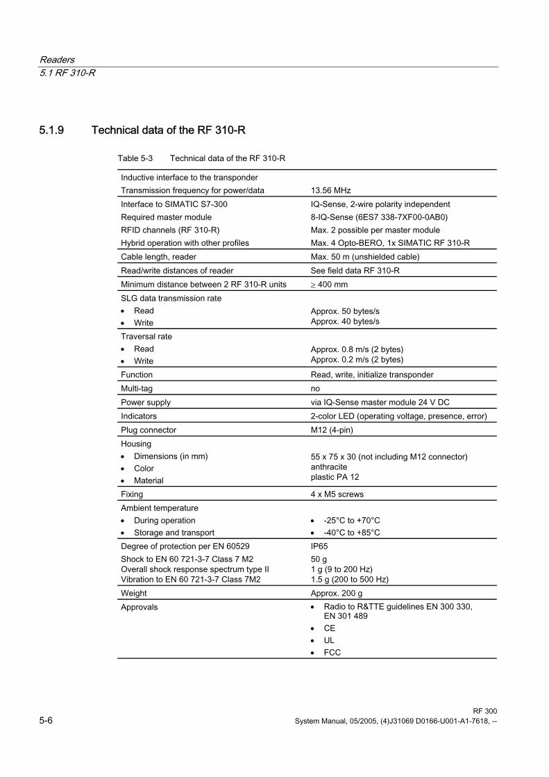
5.1.9 Technical data of the RF 310-R
Table 5-3 Technical data of the RF 310-R
Inductive interface to the transponder Transmission frequency for power/data
13.56 MHz
Interface to SIMATIC S7-300 Required master module RFID channels (RF 310-R) Hybrid operation with other profiles
IQ-Sense, 2-wire polarity independent 8-IQ-Sense (6ES7 338-7XF00-0AB0) Max. 2 possible per master module Max. 4 Opto-BERO, 1x SIMATIC RF 310-R
Cable length, reader Max. 50 m (unshielded cable) Read/write distances of reader See field data RF 310-R Minimum distance between 2 RF 310-R units ≥ 400 mm SLG data transmission rate • Read • Write
Approx. 50 bytes/s Approx. 40 bytes/s
Traversal rate • Read • Write
Approx. 0.8 m/s (2 bytes) Approx. 0.2 m/s (2 bytes)
Function Read, write, initialize transponder Multi-tag no Power supply via IQ-Sense master module 24 V DC Indicators 2-color LED (operating voltage, presence, error) Plug connector M12 (4-pin) Housing • Dimensions (in mm) • Color • Material
55 x 75 x 30 (not including M12 connector) anthracite plastic PA 12
Fixing 4 x M5 screws Ambient temperature • During operation • Storage and transport
• -25°C to +70°C • -40°C to +85°C
Degree of protection per EN 60529 Shock to EN 60 721-3-7 Class 7 M2 Overall shock response spectrum type II Vibration to EN 60 721-3-7 Class 7M2
IP65 50 g 1 g (9 to 200 Hz) 1.5 g (200 to 500 Hz)
Weight Approx. 200 g Approvals • Radio to R&TTE guidelines EN 300 330,
EN 301 489 • CE • UL • FCC

Readers 5.1 RF 310-R
RF 300 System Manual, 05/2005, (4)J31069 D0166-U001-A1-7618, -- 5-7
5.1.10 FCC information Siemens SIMATIC RF 300
FCC ID: xxxxxxxx
This device complies with part 15 of the fcc rules. Operation is subject to the following two conditions:
(1) This device may not cause harmful interference, and
(2) This device must accept any interference received, including interference that may cause undesired operation.
Caution
Any changes or modifications not expressly approved by the party responsible for
compliance could void the user's authority to operate the equipment.
5.1.11 RF 310-R ordering data
RF 310-R Order No. with IQ-Sense interface for SIMATIC S7-300 ET 200M IP65 -25° to +70°C 55 x 75 x 30 mm Max. limit distance: 30 mm with integrated antenna
6GT2 801-0AA00

Readers 5.1 RF 310-R
RF 300 5-8 System Manual, 05/2005, (4)J31069 D0166-U001-A1-7618, --
5.1.12 Dimension drawing
Figure 5-4 RF 310-R dimension drawing

RF 300 System Manual, 05/2005, (4)J31069 D0166-U001-A1-7618, -- 6-1
Transponder/tags 6Transponders consist predominantly of logic, FRAM and/or EEPROM.
If a transponder moves into the transmission field of the reader, the necessary power for all of the circuit components is generated and monitored by the power supply unit. The pulse-coded information is prepared in such a way that it can be processed further as pure digital signals. The handling of data, including check routines, is performed by the control unit, which also manages the various memories.

Transponder/tags 6.1 RF 320-T
RF 300 6-2 System Manual, 05/2005, (4)J31069 D0166-U001-A1-7618, --
6.1 RF 320-T
6.1.1 Features
RF 320-T transponder Features
Applications Identification tasks on small assembly lines in harsh industrial environments
Memory Read-only area (4 bytes UID) User data area (20 bytes)
Read/write range Max. 18 mm (in conjunction with reader RF 310-R)
Mounting on metal No: distance to metal must be at least 10 mm

Transponder/tags 6.1 RF 320-T
RF 300 System Manual, 05/2005, (4)J31069 D0166-U001-A1-7618, -- 6-3
6.1.2 Metal-free area
Direct mounting of the RF 320-T on metal Direct mounting of the RF 320-T on metal is not allowed.
The following figures show the minimum distance between the RF 320-T and metal:
Figure 6-1 Mounting of the RF 320-T on metal with spacer
Flush-mounting of the RF 320-T in metal
Figure 6-2 Flush-mounting of the RF 320-T in metal with spacer

Transponder/tags 6.1 RF 320-T
RF 300 6-4 System Manual, 05/2005, (4)J31069 D0166-U001-A1-7618, --
6.1.3 Field data
Table 6-1 Field data for transponder RF 320-T to reader RF 310-R
Transponder RF 320-T to reader RF 310-R
Working distance (Sa) 0 to 12 mm Limit distance (Sg) 18 mm Transmission window (L) 30 mm
Table 6-2 Field data for transponder RF 320-T to RF 320-T
Transponder RF 320-T to transponder RF 320-T Minimum distance 100 mm

Transponder/tags 6.1 RF 320-T
RF 300 System Manual, 05/2005, (4)J31069 D0166-U001-A1-7618, -- 6-5
6.1.4 Technical data
Table 6-3 Technical data of the RF 320-T
Memory size 20 bytes EEPROM (r/w), 4 bytes UID (ro) Memory organization Byte-oriented access, write protection possible in
4-byte blocks MTBF 8 x 10⁶ h Read cycles Unlimited Write cycles, min. 50 000 at ≤ 40 °C, typical > 1 000 000 Data retention time > 10 years (at < +40 °C) Read/write distance, max. 18 mm (see field data) Energy source Inductive power transmission Shock/vibration-resistant to EN 60721-3-7, Class 7 M3
100 g/20 g
Torsion and bending load not permissible Fixing Adhesive/M3 screws Recommended spacing from metal > 10 mm Degree of protection per EN 60529 • IP67/IPX9K
Housing • Dimensions • Color/material
Button • Ø 27 mm x 4 mm • Black/epoxy resin
Ambient temperature • During operation • Storage and transport
• -25 to +85 °C • -40 to +125 °C
Weight Approx. 5 g
Note
All the technical data listed are typical data and are applicable for an ambient temperature of between 0 C and +50°C and a metal-free environment.

Transponder/tags 6.1 RF 320-T
RF 300 6-6 System Manual, 05/2005, (4)J31069 D0166-U001-A1-7618, --
6.1.5 Ordering data
RF 320-T transponder Order No.
Transponder RF 320-T, button, 20-byte EEPROM IP 67 -25 to +85 °C d = 27 mm x 4 mm
6GT2 800-1CA00
6.1.6 Dimension drawing
Dimensions of the device
Dimensions in millimeters

Transponder/tags 6.2 RF 340-T
RF 300 System Manual, 05/2005, (4)J31069 D0166-U001-A1-7618, -- 6-7
6.2 RF 340-T
6.2.1 Features
RF 340-T transponder Features
Applications Identification tasks on small assembly lines in harsh industrial environments
Memory Read-only area (4 bytes UID) Read/write memory (8 KB)
Read/write range (in conjunction with reader RF 310-R)
Max. 30 mm
Mounting on metal Yes: can be directly mounted on metal

Transponder/tags 6.2 RF 340-T
RF 300 6-8 System Manual, 05/2005, (4)J31069 D0166-U001-A1-7618, --
6.2.2 Metal-free area Direct mounting of the RF 340-T on metal is allowed.
Direct mounting of the RF 340-T on metal
Figure 6-3 Direct mounting of the RF 340-T on metal:
Flush-mounting of the RF 340-T in metal:
Figure 6-4 Flush-mounting of the RF 340-T in metal:

Transponder/tags 6.2 RF 340-T
RF 300 System Manual, 05/2005, (4)J31069 D0166-U001-A1-7618, -- 6-9
6.2.3 Field data
Table 6-4 Field data for transponder RF 340-T to reader RF 310-R
Transponder RF 340-T to reader RF 310-R
Working distance (Sa) 0 to 20 mm Limit distance (Sg) 30 mm Transmission window (L) 40 mm
Table 6-5 Transponder RF 340-T to transponder RF 340-T
Transponder RF 340-T to transponder RF 340-T Minimum distance 100 mm

Transponder/tags 6.2 RF 340-T
RF 300 6-10 System Manual, 05/2005, (4)J31069 D0166-U001-A1-7618, --
6.2.4 Technical data
Table 6-6 Technical data of the RF 340-T
Memory size 8 KB Memory organization 8 bit / bytewise Memory configuration • Serial number (UID) • Application memory
4 bytes (fixed code) 8188 bytes r/w
Storage technology FRAM MTBF, at +40 °C > 1.5 x 10⁶ h Write cycles, at +40°C Virtually unlimited (>1010) Read cycles Unlimited Transmission rate • Reading • Writing
with RS 422 reader: Approx. 0.3 ms / byte approx. 0.3 ms / byte
with IQ-Sense reader: Approx. 20 ms / byte approx. 25 ms / byte
Data retention > 10 years Read/write distance 0 to max. 60 mm (depends on reader used) Multitag capability max. 4 transponders Recommended spacing from metal can be directly mounted on metal Power supply Inductive, without battery Degree of protection to EN 60529 Shock to EN 60721-3-7 Vibration to EN 60721-3-7 Torsion and bending load
IP68/IPX9K 50 g 20 g Not permitted permanently
Housing dimensions Color Material Fixing
48 x 25 x 15 mm (L x W x H) Anthracite PA12 2 screws (M3)
Ambient temperature • During operation • Storage and transport
-25°C to +85°C -40°C to +85°C
Weight Approx. 25 g

Transponder/tags 6.2 RF 340-T
RF 300 System Manual, 05/2005, (4)J31069 D0166-U001-A1-7618, -- 6-11
6.2.5 Ordering data
Ordering data
RF 340-T Order No.
RF 340-T transponder 8 KB FRAM 48 x 25 x 15 mm (L x W x H)
6GT2 800-4BB00
6.2.6 Dimension drawing
Dimensions of the device
Dimensions in millimeters

Transponder/tags 6.2 RF 340-T
RF 300 6-12 System Manual, 05/2005, (4)J31069 D0166-U001-A1-7618, --

RF 300 System Manual, 05/2005, (4)J31069 D0166-U001-A1-7618, -- 7-1
Communication modules 7The communication modules (interface modules) are links between the RFID components (reader and transponder) and the higher-level control systems (e.g. SIMATIC S7) or PC or computers.

Communication modules 7.1 8xIQ-Sense
RF 300 7-2 System Manual, 05/2005, (4)J31069 D0166-U001-A1-7618, --
7.1 8xIQ-Sense The 8xIQ-Sense module in conjunction with the RF 310-R handles the function of the communication module in SIMATIC RF 300. It can be operated centrally in an S7-300 or decentrally in an ET 200M.
7.1.1 Features
8xIQ-Sense Features
Operation Centralized or distributed
Communication with up to 8 IQ-Sense devices fitted with IQ-Sense communication interfaces
Status displays Status LED for each channel (green) (for BERO only) Fault LED (red)

Communication modules 7.1 8xIQ-Sense
RF 300 System Manual, 05/2005, (4)J31069 D0166-U001-A1-7618, -- 7-3
7.1.2 Indicators
Status displays The 8xIQ-Sense module has the following LEDs: A green LED, which has no function for RFID devices, and a red SF LED (system fault LED), which indicates the diagnostic state of the module.
LEDs Labeling LED
status Meaning
Green LED per channel
0…7 Has no function here
Illuminated
Module fault, sensor fault, active teach-in operation, external auxiliary voltage missing
Red SF
Not illuminated
No fault or no active teach-in operation

Communication modules 7.1 8xIQ-Sense
RF 300 7-4 System Manual, 05/2005, (4)J31069 D0166-U001-A1-7618, --
7.1.3 Configuration
Centralized S7-300 configuration
Figure 7-1 Configurator for 8xIQ-Sense with reader RF 310-R (centralized configuration)
Distributed configuration (ET 200M)
Figure 7-2 Configurator for 8xIQ-Sense with reader RF 310-R (distributed configuration)

Communication modules 7.1 8xIQ-Sense
RF 300 System Manual, 05/2005, (4)J31069 D0166-U001-A1-7618, -- 7-5
7.1.4 Addressing The address range of the 8xIQ-Sense module is 16 bytes I/O.
This is independent of the choice of channel profiles on the connected device
(i.e. the IQ profile IDs in HW Config).
Access to memory areas A direct association exists between the number of the channel to which the IQ-Sense device is connected (terminal) and the input and output data area of the module. Based on the address range, the following addresses can be used to access the memory areas:
Address = module initial address + (channel no. x 2)

Communication modules 7.1 8xIQ-Sense
RF 300 7-6 System Manual, 05/2005, (4)J31069 D0166-U001-A1-7618, --
Example Module initial address = 280
I/O address for channel 3: 286
Figure 7-3 8xIQ-Sense module: Assignment of terminal pair to memory area
Note
A maximum of two read/write devices can be operated!
Each read/write device uses channel numbers 0 to 3 or 4 to 7.

Communication modules 7.1 8xIQ-Sense
RF 300 System Manual, 05/2005, (4)J31069 D0166-U001-A1-7618, -- 7-7
7.1.5 Technical data
Voltages and currents Rated supply voltage Reverse polarity protection
24 V DC yes
Galvanic isolation • Between the channels • Between channels and backplane bus
no yes
Permissible potential difference Between different circuits
75 V DC / 60 V AC
Insulation tested at 500 V DC Current input • from the backplane bus • from L+ power supply
120 mA typical 500 mA max.
Module power loss 2.5 W typical Module-specific data Number of channels Channels for RFID systems
8 2
Cable length, unshielded 50 m max. Dimensions and weight Dimensions w x h x d (mm) 40 x 125 x 120 Weight Approx. 235 g
7.1.6 Ordering data
8xIQ-Sense Order No.
SIMATIC S7-300 IQ-Sense SM338 for S7-300 and ET200M for the connection of up to 8xIQ-Sense sensors Optical sensors, ultrasonic sensors and RF identification systems can be connected.
6ES7 3387XF000AB0

Communication modules 7.1 8xIQ-Sense
RF 300 7-8 System Manual, 05/2005, (4)J31069 D0166-U001-A1-7618, --
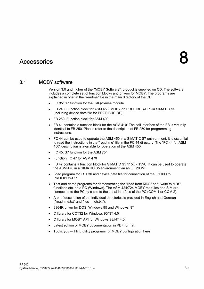
RF 300 System Manual, 05/2005, (4)J31069 D0166-U001-A1-7618, -- 8-1
Accessories 88.1 MOBY software
Version 3.0 and higher of the "MOBY Software", product is supplied on CD. The software includes a complete set of function blocks and drivers for MOBY. The programs are explained in brief in the "readme" file in the main directory of the CD:
• FC 35: S7 function for the 8xIQ-Sense module
• FB 240: Function block for ASM 450; MOBY on PROFIBUS-DP via SIMATIC S5 (including device data file for PROFIBUS-DP)
• FB 250: Function block for ASM 400
• FB 41 contains a function block for the ASM 410. The call interface of the FB is virtually identical to FB 250. Please refer to the description of FB 250 for programming instructions.
• FC 44 can be used to operate the ASM 450 in a SIMATIC S7 environment. It is essential to read the instructions in the "read_me" file in the FC 44 directory. The "FC 44 for ASM 450" description is available for operation of the ASM 450.
• FC 45: S7 function for the ASM 754
• Function FC 47 for ASM 470
• FB 47 contains a function block for SIMATIC S5 115U - 155U. It can be used to operate the ASM 470 in a SIMATIC S5 environment via an ET 200M.
• Load program for ES 030 and device data file for connection of the ES 030 to PROFIBUS-DP
• Test and demo programs for demonstrating the "read from MDS" and "write to MDS" functions etc. on a PC (Windows). The ASM 424/724 MOBY modules and SIM are connected to the PC by cable to the serial interface of the PC (COM 1 or COM 2).
• A brief description of the individual directories is provided in English and German ("read_me.txt" and "lies_mich.txt").
• 3964R driver for DOS, Windows 95 and Windows NT
• C library for CCT32 for Windows 95/NT 4.0
• C library for MOBY API for Windows 98/NT 4.0
• Latest edition of MOBY documentation in PDF format
• Tools: you will find utility programs for MOBY configuration here

Accessories 8.1 MOBY software
RF 300 8-2 System Manual, 05/2005, (4)J31069 D0166-U001-A1-7618, --
The "MOBY Software" CD has a user-friendly interface based on HTML. When you run start.exe, a window appears with the following main menu items:
• FC for S7
• FB for S5
• PC Support
• Doc
• Tools
• Demo
• News
Notes on MOBY software and licensing When purchasing an interface module or SIM, no software or documentation is supplied. The "MOBY Software" CD-ROM contains all available FBs/FCs for the SIMATIC, C libraries for Windows 98/NT, demo programs, etc. and needs to be ordered separately. In addition, the CD-ROM contains the complete RFID documentation (German, English and French) in PDF format.
The purchase of an interface module or SIM includes a payment for the use of the software, including documentation, on the "MOBY Software“ CD-ROM and the purchaser acquires the right to make copies (copy license) insofar as they are required as part of the customer-specific application or
development for the plant.
The enclosed contract pertaining to the use of software products against a one-off payment shall apply in addition.

RF 300 System Manual, 05/2005, (4)J31069 D0166-U001-A1-7618, -- A-1
Appendix AA.1 Certificates and approvals
DIN ISO 9001 certificate The quality assurance system for the entire product process (development, production, and marketing) at Siemens fulfills the requirements of ISO 9001 (corresponds to EN29001: 1987).
This has been certified by DQS (the German society for the certification of quality management systems).
EQ-Net certificate no.: 1323-01
Certifications for the United States, Canada, and Australia
Safety
One of the following markings on a device is indicative of the corresponding approval:
Underwriters Laboratories (UL) per UL 60950 (I.T.E) or per UL 508 (IND.CONT.EQ)
Underwriters Laboratories (UL) according to Canadian standard C22.2 No. 60950 (I.T.E) or C22.2 No. 142 (IND.CONT.EQ)
Underwriters Laboratories (UL) according to standard UL 60950, Report E11 5352 and Canadian standard C22.2 No. 60950 (I.T.E) or UL508 and C22.2 No. 142 (IND.CONT.EQ)
UL recognition mark
Canadian Standard Association (CSA) per Standard C22.2. No. 60950 (LR 81690) or per C22.2 No. 142 (LR 63533)
Canadian Standard Association (CSA) per American Standard UL 60950 (LR 81690) or per UL 508 (LR 63533)

Appendix A.1 Certificates and approvals
RF 300 A-2 System Manual, 05/2005, (4)J31069 D0166-U001-A1-7618, --
EMC
USA Federal Communications Commission Radio Frequency Interference Statement
This equipment has been tested and found to comply with the limits for a Class A digital device, pursuant to Part 15 of the FCC Rules. These limits are designed to provide reasonable protection against harmful interference when the equipment is operated in a commercial environment. This equipment generates, uses, and can radiate radio frequency energy and, if not installed and used in accordance with the instruction manual, may cause harmful interference to radio communications. Operation of this equipment in a residential area is likely to cause harmful interference in which case the user will be required to correct the interference at his own expense.
Shielded Cables Shielded cables must be used with this equipment to maintain compliance with FCC regulations.
Modifications Changes or modifications not expressly approved by the manufacturer could void the user's authority to operate the equipment.
Conditions of Operations This device complies with Part 15 of the FCC Rules. Operation is subject to the following two conditions: (1) this device may not cause harmful interference, and (2) this device must accept any interference received, including interference that may cause undesired operation.
CANADA Canadian Notice This Class B digital apparatus complies with Canadian ICES-003. Avis Canadien Cet appareil numérique de la classe b est conforme à la norme NMB-003
du Canada.
AUSTRALIA
This product meets the requirements of the AS/NZS 3548 Norm.

Appendix A.2 Service and support
RF 300 System Manual, 05/2005, (4)J31069 D0166-U001-A1-7618, -- A-3
A.2 Service and support
Technical support You can reach the technical support team for all A&D projects at
• Telephone: +49 (0) 180 5050 222
• Fax: +49 (0) 180 5050 223
Internet • Visit our site on the Internet at:
http://www.siemens.com/automation/service&support
• You can send a support query to:
http://www.siemens.de/automation/support-request
• You can find the latest general information about our identification systems on the Internet at: http://www.siemens.de/simatic-sensors
• The online catalog and the online ordering system is available at:
http://mall.automation.siemens.com/
A.3 Contact partners If you have any further questions on the use of our products, please contact one of our representatives at your local Siemens office.
The addresses are found on the following pages:
• On the Internet at: http://www.siemens.com/automation/partner
• In catalog CA 01
• In Catalog FS 10 specially for factory automation sensors

Appendix A.4 Application consulting
RF 300 A-4 System Manual, 05/2005, (4)J31069 D0166-U001-A1-7618, --
A.4 Application consulting For questions about special applications, please send an e-mail to the following address: [email protected]
or call the following phone number: 0911/895-5775
A.5 Training
Training center We offer appropriate courses to get you started. Please contact your regional Training Center, or the central Training Center in D-90327 Nuremberg.
Telephone: +49 (911) 895-3200
http://www.sitrain.com

RF 300 System Manual, 05/2005, (4)J31069 D0166-U001-A1-7618, -- Glossary-1
List of abbreviations
ASM Interface module
CSA Canadian Standard Association
EMC Electromagnetic compatibility
FB Function Block
FC Function
IEC International Electrotechnical Commission
L Length of a transmission window
MDS Mobile data memory
RFID Radio Frequency Identification Devices
Sa Operating distance between MDS and SLG
List of abbreviations
RF 300 Glossary-2 System Manual, 05/2005, (4)J31069 D0166-U001-A1-7618, --
Sg Limit distance
SLG Write/read device
SP Intersection of the axes of symmetry of the MDS
Tag See transponder
TPDR Transponder
UL Underwriter Laboratories, USA
VDE Verband Deutscher Elektrotechniker [Association of German Electrical Engineers]
XPDR Transponder

RF 300 System Manual, 05/2005, (4)J31069 D0166-U001-A1-7618, -- Glossary-1
Glossary
Active field Area with minimum field strength containing the transmission window, as well as the areas in which the field strength is no longer sufficient for data exchange.
Active surface See active field
Automation system (AS) A programmable logical controller (PLC) of the SIMATIC S7 system, comprising a central controller, a CPU and various I/O modules.
Battery-free data memory Mobile data memories which operate without batteries. Power is supplied to the data memory across an electromagnetic alternating field.
CE mark Communauté Européenne (product mark of the European Union)
Data transmission rate Unit of measurement for the volume of data transmitted within a unit of time, e.g. bytes/s
Dwell time The dwell time is the time in which the transponder dwells within the transmission window of a read/write device. The read/write device can exchange data with the transponder during this time.
Dynamic mode In dynamic mode, the data carrier moves past the read/write device at a traversing rate which depends on the configuration. Various checking mechanisms (listen-in check, CRC, ECC, etc.) ensure error-free data transfer even under extreme environmental conditions. A serial connection (up to 1000 m) is used to connect the read/write device directly to an interface module, PC, or any other system.

Glossary
RF 300 Glossary-2 System Manual, 05/2005, (4)J31069 D0166-U001-A1-7618, --
Electromagnetic compatibility Electromagnetic compatibility is the ability of an electrical or electronic device to operate satisfactorily in an electromagnetic environment without affecting or interfering with the environment over and above certain limits.
Equipotential bonding Potential differences between different parts of a plant can arise due to the different design of the plant components and different voltage levels. It is necessary to compensate for these differences by equipotential bonding: this is done by combining the equipotential bonding conductors of power components and non-power components on a centralized equalizing conductor.
ESD Directive Directive for handling ESDs.
Frequency hopping Automatic search for free channels.
In frequency hopping, data packets are transferred between the communication partners on constantly changing carrier frequencies. This makes it possible to react to interference from devices transmitting signals in the same frequency range. If an attempt to send a data packet is unsuccessful, the packet can be transmitted again on a different carrier frequency.
IQ-Sense interface Simple interface on the IQ-Sense module, using a standard design for all types of sensors, enabling integrated data exchange between the sensor and control system.
Limit distance The limit distance is the maximum clear distance between the upper surface of the read/write device and the transponder, at which the transmission can still function under normal conditions.
Metal-free area Distance/area which must be maintained between the transponder and metal in order to prevent interference during data transfer between the transponder and read/write device.
Mobile data memory (MDS) See transponder
Multi-tag capability Multi-tag capability means the ability to use several read/write devices which communicate simultaneously with different data carriers.

Glossary
RF 300 System Manual, 05/2005, (4)J31069 D0166-U001-A1-7618, -- Glossary-3
Programmable logic controller (PLC) The programmable logical controllers (PLCs) of the SIMATIC S5 systems consist of a central controller, one or more CPUs, and various other modules (e.g. I/O modules).
Read/write devices (SLG) See readers
Read/write distance See transmission distance
Reader/writer See write/read device
RFID systems SIMATIC RF identification systems control and optimize material flow and production sequences. They identify reliably, quickly and economically, use non-contact data communication technology, and store data directly on the product. They are also resistant to contamination.
Secondary fields The strength of the secondary fields, which exist in addition to the transmission window, is usually lower than that of the transmission window and depends on the metallic environment. Secondary fields should not be used in configuring.
Static mode In static mode, the transponder is positioned at a fixed distance (maximum: limit distance) exactly over the read/write device.
Telegram cycles The transfer of a read or write command takes place in three cycles, known as telegram cycles. 1 or 2 bytes of user data can be transferred with each command. The acknowledgement transfer (status or read data) takes place in 3 further cycles.
Transmission distance Distance between communication module (read/write device) and transponder (mobile data memory)
Transmission window Area in which reliable data exchange between transponder and read/write device is possible due to a particular minimum field strength.

Glossary
RF 300 Glossary-4 System Manual, 05/2005, (4)J31069 D0166-U001-A1-7618, --

RF 300 System Manual, 05/2005, (4)J31069 D0166-U001-A1-7618, -- Index-1
Index
8 8xIQ-Sense module, 7-2
Addressing, 7-5 Configuration, 7-4 Features, 7-2 Indicators, 7-3
A Active field, 4-2 Active surface, 4-4 Application consulting, A-4 Application Planning
SIMATIC RF 300, 4-1 Approvals, A-1
C Cabinet configuration, 4-32 Calculation example, 4-9 Certificates, A-1 Communication, 4-7
between RF 300 components, 4-7 Communication modules
8xIQ-Sense module, 7-2 Communication time, 4-7
for fault-free data transfer, 4-7 Configuration, 7-4 Contact partners, A-3 Coupling paths, 4-31
D Data volume
Relationship between speed and, 4-13 Design
Centralized, 7-4 Distributed, 7-4
Dimension drawing Reader RF 310-R, 5-8
Direction of motion Transponder, 4-4
Dwell time Transponder, 4-6
Dynamic mode, 4-5 Dynamic mode
Dwell time of the transponder, 4-6
E Electromagnetic compatibility
Coupling paths, 4-31 Electromagnetic interference, 4-29 EMC Directive, A-2 EMC Guidelines
Avoiding interference, 4-35 Basic rules, 4-28 Cabinet configuration, 4-32 Cable shielding, 4-37 Definition, 4-27 Equipotential bonding, 4-36 Overview, 4-26 Propagation of electromagnetic interference, 4-29
Equipotential bonding, 4-36
F Field data
Readers, 4-12 Reduction due to metal, 4-20 RF 320-T transponder, 6-4 RF 340-T transponder, 6-9 Transponder, 4-12
Flush-mounting of transponders and readers, 4-16
I Identification system
Inductive, 3-2 Inductive alternating field, 4-2 Installation
Several readers, 4-17

Index
RF 300 Index-2 System Manual, 05/2005, (4)J31069 D0166-U001-A1-7618, --
Installation guidelines, 4-14 Interference sources
Electromagnetic, 4-30 IQ-Sense interface
Pin assignment, 5-5
M Main applications
RF 300, 3-2 Metal-free area
Reader RF 310-R, 5-3 RF 320-T transponder, 6-3 RF 340-T transponder, 6-8
Minimum distance Reader to reader, 4-12 Transponder to transponder, 4-12
MOBY software, 8-1 Mounting options
of transponders and readers, 4-18
O Ordering data
Reader RF 340-T, 6-11
R Read/write distance, 4-2 Reader RF 310-R, 5-2
Cable and connector pin assignment, 5-5 Dimension drawing, 5-8 Features, 5-2 Indicators, 5-2 Metal-free area, 5-3 Minimum distance, 5-4 Pin assignment of IQ-Sense interface, 5-5 Reliable data exchange, 5-3 Technical data, 5-6
Readers, 5-1 Mounting, 4-17
Reducing interference due to metal, 4-15 Reduction of field data, 4-20 Resistance to chemicals
Transponder, 4-21 RF 300
Applications, 3-2 Main applications, 3-2
RF 320-T transponder, 6-6 Features, 6-2 Field data, 6-4 Metal-free area, 6-3
Technical data, 6-5 RF 340-T transponder
Features, 6-7 Field data, 6-9 Metal-free area, 6-8 Technical data, 6-10
RFID systems Overview, 3-1
S Safety information, 2-1 Secondary fields, 4-3 Service, A-3 Shielding, 4-37 Static mode, 4-5 Static mode
Dwell time of the transponder, 4-6 Support, A-3 System components
Overview, 3-3 System overview
RFID systems, 3-1 Systems
RFID, 3-1
T Technical data
Reader RF 310-R, 5-6 RF 320-T transponder, 6-5 RF 340-T transponder, 6-10
Time constants, 4-8 Tolerance of pallet side transport, 4-10 Tolerance of pallet transport height, 4-10 Tracking
Tolerance, 4-3 Tracking tolerances, 4-3 Training center, A-4 Transmission window
Impact of metal, 4-19 Width, 4-3
Transponder, 6-1 Active surface, 4-4 Directions of motion, 4-4 Dwell time, 4-6 Mounting on metal, 4-18 Resistance to chemicals, 4-21 RF 340-T, 6-7
Transponder speed, 4-13

Index
RF 300 System Manual, 05/2005, (4)J31069 D0166-U001-A1-7618, -- Index-3
U User data
Calculation of maximum amount of, 4-7

Index
RF 300 Index-4 System Manual, 05/2005, (4)J31069 D0166-U001-A1-7618, --


Siemens AG
Automation and DrivesFactory Automation SensorsPostfach 484890327 NÜRNBERGFEDERAL REPUBLIC OF GERMANY
www.siemens.com/simatic-sensors