rhino-stop® truck guard installation manual®-truck-guard-installation... · if installing...
TRANSCRIPT

safedirection.com.au
RRHHIINNOO--SSTTOOPP®®
TTrruucckk--GGuuaarrdd
IInnssttaallllaattiioonn MMaannuuaall
Ref: IM 007/01

safedirection.com.au
2
RRHHIINNOO--SSTTOOPP®®
IInnssttaallllaattiioonn MMaannuuaall
Table of Contents
1.0 Introduction .............................................................................................................................................................. 4
2.0 Specifications ........................................................................................................................................................... 4
3.0 Bill of Materials ..................................................................................................................................................... 5
4.0 Component Identification .......................................................................................................................... 5
5.0 Tools Required ....................................................................................................................................................... 7
5.1 Recommended PPE ................................................................................................................................................. 7
6.0 Site Establishment ............................................................................................................................................. 7
6.1 Traffic Control ............................................................................................................................................................. 7
6.2 Underground Services ............................................................................................................................ 7
6.3 Overhead Obstructions .......................................................................................................................... 7
6.4 Unloading Exclusion Zone .................................................................................................................... 7
6.5 Concrete Curing ......................................................................................................................................................... 8
6.6 Concrete Substrate Thickness ............................................................................................................ 8
6.7 Bolt Edge Distance .................................................................................................................................... 8
7.0 Set-Out ............................................................................................................................................................................. 8
7.1 Cutting and Drilling ................................................................................................................................................ 8
8.0 Anchor Bolt Installation .............................................................................................................................. 9

safedirection.com.au
3
RRHHIINNOO--SSTTOOPP®® TTrruucckk--GGuuaarrdd
IInnssttaallllaattiioonn MMaannuuaall
Table of Contents (continued)
9.0 Assembly Sequence ....................................................................................................................................... 10
9.1 RHINO-STOP® Truck-Guard Type 1 ......................................................................................................... 10
9.2 RHINO-STOP® Truck-Guard Type 2 ............................................................................................... 11
Installation Checklist ............................................................................................................................................. 15
List of Drawings
RHINO-STOP® Truck-Guard Type 1 Assembly Drawing ................................................. 17
RHINO-STOP® Truck-Guard Type 2 Assembly Drawing ................................................... 18

safedirection.com.au
4
RRHHIINNOO--SSTTOOPP®® TTrruucckk--GGuuaarrdd IInnssttaallllaattiioonn MMaannuuaall
1.0 RHINO-STOP®
Truck-Guard
Providing superior design, rapid installation and driver confidence, RHINO-STOP® Truck-Guard is compliant to the 40kN impact force described in AS/NZS 1170.1: Structural Design Actions.
The 40kN impact condition represents a collision from a heavy vehicle with a high centre-of-gravity.
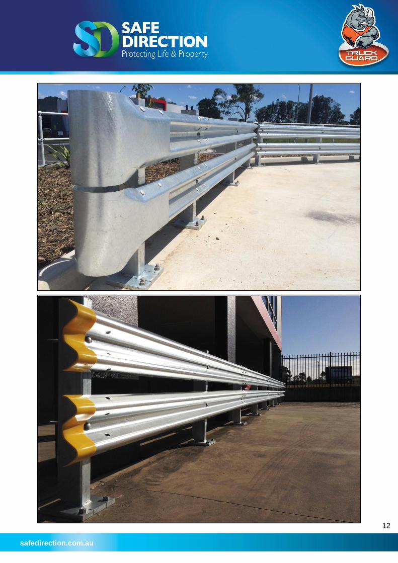
RHINO-STOP® Truck-Guard may be installed as a standalone post and w-beam guardrail configuration or with mesh infill when fall protection for pedestrians is required. The modular design of RHINO-STOP® Truck-Guard allows the system to be configured to suit site requirements using standard components.
RHINO-STOP® Truck-Guard is an energy-absorbing, semi-rigid barrier providing reduced dynamic deflection. The energy absorbing feature reduces damage to the impacting vehicle and the barrier system. The semi-rigid feature of RHINO-STOP® reduces the space requirement between fixed object hazards and the barrier, conserving valuable floor space.
The twin guardrail feature of RHINO-STOP® Truck-Guard provides a wider lateral catching area and is suited to warehouse conditions where a variety of vehicle types and geometries are often encountered.
2.0 Specifications
Compliance: AS/NZS 2890.1
AS/NZS 1170.1 40kN - Type G Medium Traffic Areas
Post height: 1050mm
Rail height: 600mm (lower rail) 1030mm (upper rail)
Base plate: 250mm x 250mm
System width: 230mm
Post spacing: 2.0m centres (max.)
Anchor type*: M20 x 160mm Clawbolt
Anchors per post: 2 off
Hole diameter: 20mm
Substrate Thickness: 200mm minimum (32Mpa)
Bolt Embedment: 100mm minimum
Bolt Edge Distance: 125mm minimum
Min. number of posts: 5 off per installation
Post deflection: 240mm for 40kN impact (at the top of the post)
Available attachments: Mesh infill Finish: Hot dip galvanised
*Chemical anchor options available upon request

safedirection.com.au
5
RRHHIINNOO--SSTTOOPP®® TTrruucckk--GGuuaarrdd IInnssttaallllaattiioonn MMaannuuaall
3.0 Bill of Materials
Item Description SD Item Number
4m W-Beam Guardrail GR-WB-SR-4000-AG
Truck-Guard Post GR-PB-RS-1050-AG
2400mm x 900mm Mesh Panel GR-MX-MX-2409-AG
Splice Bolt & Nut M16x32mm Mushroom Head GR-FS-16-0032-MG
Post Bolt & Nut M16x180mm Mushroom Head GR-FS-16-0180-MG
Self Drilling Screw 12 gauge x 35mm GR-FS-12-0035-TG
Mesh Washer GR-FS-08-0000-AG
Clawbolt Stud Anchor M20x160mm GR-FS-20-0160-HG
4.0 Component Identification
M16 x 32mm Splice Bolt & Nut
M20 x 160mm Clawbolt Stud Anchor
Mesh Washer 35mm Tek Screw
M16 x 180mm Post Bolt/Nut

safedirection.com.au
6
RRHHIINNOO--SSTTOOPP®® TTrruucckk--GGuuaarrdd IInnssttaallllaattiioonn MMaannuuaall
W-Beam Guardrail
Mesh Infill Panel
Short Bullnose Yellow End Cap
Truck-Guard Post

safedirection.com.au
7
RRHHIINNOO--SSTTOOPP®® TTrruucckk--GGuuaarrdd IInnssttaallllaattiioonn MMaannuuaall
5.0 Tools Required
Tools required for the installation of RHINO-STOP® Truck-Guard includes;
Drill with 20mm masonry bit;
Air compressor;
Drill driver;
Hand socket;
Torque wrench;
Metal snips;
String line;
Tape measure;
Hammer;
Drop saw;
Grinder with metal cutting disk;
12mm diameter pinch bar; and
Slings or chains.
5.1 Recommended PPE
It is recommended that the following personal protective equipment (PPE) be provided;
Safety footwear;
Gloves;
Hearing protection; and
High visibility clothing.
6.0 Site Establishment
6.1 Traffic Control
Prior to the commencement of any work, the site should be evaluated for risks to workers, pedestrians and other road users. The establishment of traffic control should provide safe travel for passing vehicles and/or pedestrians and appropriately protect workers.
6.2 Underground Services
The installation of RHINO-STOP® Truck-Guard requires holes to be drilled into a concrete substrate. Prior to drilling, investigation for potential hazards, such as electrical conduits or reinforcement is recommended.
6.3 Overhead Obstructions
The site should be evaluated for potential overhead obstructions that may present a risk during the installation process. These obstructions typically include signage or lighting.
6.4 Unloading Exclusion Zone
Only appropriate load-rated slings or chains should be used for the safe unloading of product. It is recommended that an exclusion zone be maintained around the unloading process. This provides distance between moving machinery and workers in the event that goods or the machinery move unexpectedly. Unloading and the storing of the product on a level surface is recommended. Storing product adjacent to the installation area eliminates the requirement for workers to carry items over long distances.

safedirection.com.au
8
RRHHIINNOO--SSTTOOPP®® TTrruucckk--GGuuaarrdd IInnssttaallllaattiioonn MMaannuuaall
6.5 Concrete Curing
If installing RHINO-STOP® Truck-Guard on a newly poured concrete substrate, the concrete must be fully cured prior to the installation of anchor bolts. Curing time can vary from site to site and is to be advised by the site construction manager.
6.6 Concrete Substrate Thickness
The minimum concrete substrate thickness required for the use of the M20 x 160mm Clawbolt stud anchors is 200mm.
Alternate fixing methods including chemical anchor options may be available for substrates less than 200mm thick. Please contact Safe Direction for details.
6.7 Bolt Edge Distance
The minimum edge distance for the use of the M20 x 160mm Clawbolt stud anchors is 125mm.
Alternate fixing methods including chemical anchor options may be available when the edge distance is less than 125mm. Please contact Safe Direction for details.
7.0 Set-Out
It is recommended that a string line be used to establish the alignment of the post locations. When establishing the post locations, take care to note the following;
1. The back of the base plate must not extend beyond the edge of the concrete slab;
2. The maximum post spacing of RHINO-STOP® Truck-Guard is 2.0m centres;
3. The last post in the installation may be positioned at a reduced spacing (i.e. <2.0m) to cater for site dimensions
4. The w-beam guardrail panels will typically overhang the last post by 120mm;
5. A short bullnose will typically overhang the last post by 400mm;
6. A minimum of five (5) posts is required per installation;
7. Sufficient clearance behind the post to a fixed object hazard is required to allow for the deflection of the system;
7.1 Cutting & Drilling
During the assembly sequence it may be necessary to cut and drill standard length items to suit site dimensions.
Cutting of w-beam guardrails and mesh is undertaken using a metal cutting disk.
Drilling of new holes can be undertaken using a step drill bit.
Any damage to the galvanised coating shall be repaired using two (2) coats of an organic zinc rich paint.
Oxy acetylene equipment is NOT to be used to cut the w-beam guardrails and mesh.
safedirection.com.au
9
RRHHIINNOO--SSTTOOPP®® TTrruucckk--GGuuaarrdd IInnssttaallllaattiioonn MMaannuuaall
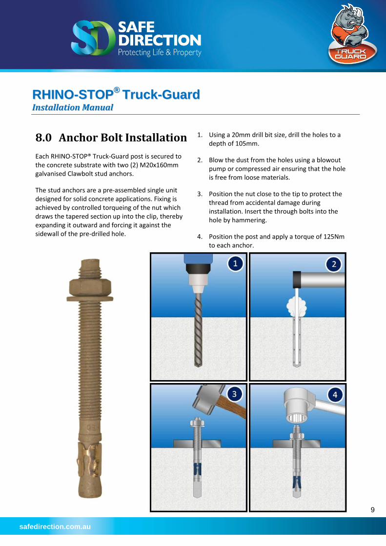
8.0 Anchor Bolt Installation
Each RHINO-STOP® Truck-Guard post is secured to the concrete substrate with two (2) M20x160mm galvanised Clawbolt stud anchors.
The stud anchors are a pre-assembled single unit designed for solid concrete applications. Fixing is achieved by controlled torqueing of the nut which draws the tapered section up into the clip, thereby expanding it outward and forcing it against the sidewall of the pre-drilled hole.
1. Using a 20mm drill bit size, drill the holes to a depth of 105mm.
2. Blow the dust from the holes using a blowout pump or compressed air ensuring that the hole is free from loose materials.
3. Position the nut close to the tip to protect the thread from accidental damage during installation. Insert the through bolts into the hole by hammering.
4. Position the post and apply a torque of 125Nm to each anchor.

safedirection.com.au
10
RRHHIINNOO--SSTTOOPP®® TTrruucckk--GGuuaarrdd IInnssttaallllaattiioonn MMaannuuaall
9.0 Assembly Sequence
9.1 RHINO-STOP® Truck-Guard Type 1
Reference Drawing: SD-WB-040
RHINO-STOP® Truck-Guard Type 1 provides vehicle barrier protection in accordance with the 40kN load (Type G) as described in AS/NZS 1170.1.
1. Install two (2) Clawbolt stud anchors and secure the post as described in Section 8.0.
2. Two (2) w-beam guardrails are installed to each post. The lower rail is positioned 600mm ground level. The upper rail is positioned 1030mm above ground level.
3. The w-beam guardrails are secured to the posts using one (1) M16 x 180mm mushroom head bolt and nut. The nut is tightened using a hand socket and 24mm attachment.
There is no torque requirement for the tightening of the post bolts. They should be tightened to a snug position.
4. The w-beam guardrails are spliced together using eight (8) M16 x 32mm mushroom head bolts and oversize nuts. The lap orientation of the rails should be consistent throughout the installation. The splice nuts are tightened using a pneumatic drill driver and 32mm attachment.
The use of a pinch bar will assist in aligning the splice holes as the bolts are inserted. The use of a driving pin to elongate the splice holes is NOT permitted.
There is no torque requirement for the tightening of the splice bolts. They should be tightened to a snug position.
5. In some cases the last post in the installation may be positioned at a reduced spacing (i.e. <2.0m) to cater for site dimensions.
In these instances, the last rail will be required to be cut to length.
Cutting of the rails is undertaken using a drop saw with a metal cutting disk. Drilling of new holes can be undertaken using a step drill bit.
Repair any damage to the galvanised coating using two (2) coats of an organic zinc rich paint.
6. Attach a yellow end cap or short bullnose to the end of the last guardrail to shield sharp edges from pedestrians.
The short bullnose is secured to the rail using four (4) M16 x 32mm mushroom head bolts and oversize nuts.
The yellow end cap slides over the end of the rail. An adhesive is recommended to prevent removal.

safedirection.com.au
11
RRHHIINNOO--SSTTOOPP®® TTrruucckk--GGuuaarrdd IInnssttaallllaattiioonn MMaannuuaall
9.2 RHINO-STOP® Truck-Guard Type 2
Reference Drawings: SD-WB-041
RHINO-STOP® Truck-Guard Type 2 provides vehicle barrier protection in accordance with the 40kN load (Type G) as described in AS/NZS 1170.1.
The mesh infill provides anti-climb and fall protection for pedestrians.
Fully assemble the barrier as described in Section 9.3 for Type 1. Once complete, undertake the following;
1. The mesh panels (2400mm wide x 900mm high) are positioned along the crest of the upper w-beam guardrail.
2. The mesh panels are secured to the top corrugation of the upper and lower w-beam guardrails at 500mm centres with one (1) 12 gauge x 35mm long self -drilling screw and one (1) mesh washer. Take care to vertically align the fixing points of the mesh panels.
Do not over-tighten the self -drilling screws.
3. Subsequent mesh panels are placed side-by-side. There is no overlapping of mesh panels.
4. Approaching the end of the installation, it may be necessary to cut the last mesh panel to length. The overhang of the mesh panel from the last post should be vertically aligned with the support angles.
Cutting of the mesh is undertaken using an angle grinder.
Repair any damage to the galvanised coating using two (2) coats of an organic zinc rich paint.
safedirection.com.au
12

safedirection.com.au
13

safedirection.com.au
14

safedirection.com.au
15
RRHHIINNOO--SSTTOOPP®® TTrruucckk--GGuuaarrdd IInnssttaallllaattiioonn CChheecckklliisstt ((PPaaggee 11 ooff 22))
Customer:
Location:
Checked By:
Signed:
Date:
Applies to the use of the M20x160mm Clawbolt Stud Anchor
The minimum substrate thickness is 200mm.
The minimum anchor bolt edge distance is 125mm.
Fresh concrete has appropriately cured as advised by the site construction manager.
Anchor holes have been drilled to a depth of 105mm ± 5mm using a 20mm drill bit.
Anchor holes have been thoroughly cleaned of debris.
Each anchor has been torqued to 125Nm.
Applies to all RHINO-STOP® Truck-Guard Configurations
Each post is secured with two (2) anchor bolts.
Post spacing does not exceed 2m.
Each installation is supported by a minimum five (5) posts.
Each installation comprises an upper and lower w-beam guardrail.
The w-beam guardrail is secured to each post using one (1) M16 x 180mm mushroom head bolt & nut.
The w-beam is spliced together using eight (8) M16 x 32mm mushroom head bolt & nuts.
All fasteners are tightened.
Any damage to the galvanised coating has been repaired using two (2) coats of a zinc rich paint.
The area around the system is clean and free from debris.
On exposed edges, a short bullnose or yellow end cap has been attached to the w-beam guardrail.
safedirection.com.au
16
RRHHIINNOO--SSTTOOPP®® TTrruucckk--GGuuaarrdd IInnssttaallllaattiioonn CChheecckklliisstt ((PPaaggee 22 ooff 22))
Customer:
Location:
Checked By:
Signed:
Date:
Applies to RHINO-STOP® Truck-Guard Type 2
The mesh panel is secured to the upper w-beam guardrail using one (1) mesh washer and self-drilling screw (14 gauge x 35mm) at 500mm centres.
The mesh panel is secured to the lower w-beam guardrail using one (1) mesh washer and self-drilling screw (14 gauge x 35mm) at 500mm centres.
The 14 gauge x 35mm self-drilling screws are not over-tightened.
There are no gaps in the system greater than 120mm.

safedirection.com.au
17

safedirection.com.au
18

safedirection.com.au
19
RRHHIINNOO--SSTTOOPP®® TTrruucckk--GGuuaarrdd IInnssttaallllaattiioonn MMaannuuaall
Safe Direction Pty Ltd Ph: 1300 063 220
E: [email protected] safedirection.com.au
ABN 53 156 459 684