rigging and installation instructions - baltimore … · rigging and installation instructions 1...
TRANSCRIPT
R_FXTv05 EN
RIGGING ANDINSTALLATION INSTRUCTIONS
FXT Cooling Towers
The BAC equipment should be rigged and installed asoutlined in this bulletin.These procedures should be thoroughly reviewed prior tothe rigging and operation to acquaint all personnel withthe procedures to be followed and to assure that allnecessary equipment will be available at the jobsite.
Be sure to have a copy of the unit certified drawingavailable for reference. If you do not have a copy of thisdrawing or if you need additional information about thisunit, contact the local BAC Balticare representative. Hisname and phone number can be found on the BACwebsite: www.BaltimoreAircoil.eu. The model type andserial number of your equipment are indicated on the unitnameplate.
.
Table of Contents Page
General Information 2
Rigging 5
Section Assembly 7
Optional Accessories Assembly 8
Inspection Prior to Start-up 9
Recommended Maintenance and Monitoring Programme
12
1
GENERAL INFORMATION
This bulletin only refers to the assembly of the unit. To ensure a
proper operation, a correct integration of the unit in the overallinstallation is mandatory. For good engineering and applicationpractices on layout, levelling, connecting pipework, etc…, pleaserefer to our website: http://www.baltimoreaircoil.eu/knowledge-center/application-information.
BAC cooling equipment is factory assembled to assure uniform
quality and minimum field assembly.Units usually shipped fully assembled. Most units can be set inplace with one lift and require only piping connections and electricalwiring before start-up.For the dimensions and weights of a specific unit or section, refer tothe certified drawing.
!Do not cover units with PVC eliminators or fill with a plastic tarpaulin. Temperature increase due to sun radiation could
deform the fill or eliminators
When the unit is delivered to the jobsite, it should be checked
thoroughly to ensure all required items have been received and arefree of any shipping damage prior to signing the bill of lading.The following parts should be inspected:
- Sheaves and belts- Bearings- Bearing supports- Fan motor(s)- Fan(s) and Fan shaft(s)- Wet deck surface- Drift eliminators- Water distribution system- Strainer(s)- Float valve assembly(s)- Interior / Exterior surfaces- Air Inlet Screens- Miscellaneous items:
An envelope with checklist is stored in a wooden no nail crate or aplastic container which is placed in the lower section. For safetyreasons, access doors / panels may be sealed with bolts. Thefollowing table specifies which wrench is required to open them.
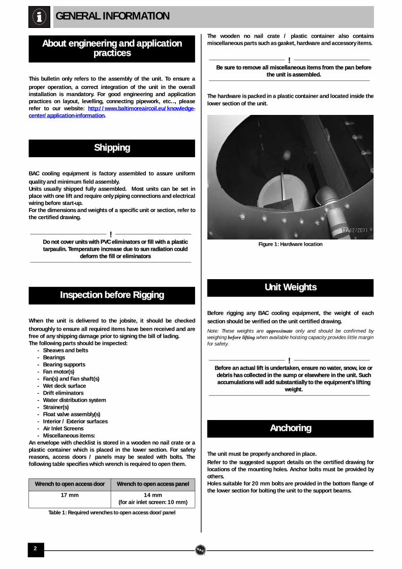
The wooden no nail crate / plastic container also containsmiscellaneous parts such as gasket, hardware and accessory items.
!Be sure to remove all miscellaneous items from the pan before
the unit is assembled.
The hardware is packed in a plastic container and located inside thelower section of the unit.
Before rigging any BAC cooling equipment, the weight of each
section should be verified on the unit certified drawing.
Note: These weights are approximate only and should be confirmed byweighing before lifting when available hoisting capacity provides little marginfor safety.
!Before an actual lift is undertaken, ensure no water, snow, ice or debris has collected in the sump or elsewhere in the unit. Such accumulations will add substantially to the equipment's lifting
weight.
The unit must be properly anchored in place.
Refer to the suggested support details on the certified drawing forlocations of the mounting holes. Anchor bolts must be provided byothers.Holes suitable for 20 mm bolts are provided in the bottom flange ofthe lower section for bolting the unit to the support beams.
About engineering and application practices
Shipping
Inspection before Rigging
Wrench to open access door Wrench to open access panel
17 mm 14 mm(for air inlet screen: 10 mm)
Table 1: Required wrenches to open access door/panel
Unit Weights
Anchoring
Figure 1: Hardware location
2
GENERAL INFORMATION
The unit must be level for proper operation and ease of piping.
All piping external to BAC cooling equipment must be supported
separately. In case the equipment is installed on vibration rails orsprings, the piping must contain compensators to eliminatevibrations carried through the external pipework.Suction pipe sizing should be done according to good practice,which may for larger flows require larger pipe diameters than thecooling tower outlet connection. In such cases adapter pieces needto be installed.
These products must be protected against damage and/or reduced
effectiveness due to possible freeze-up by mechanical andoperational methods. Please refer to the BAC Product & ApplicationHandbook or contact your local BAC Balticare representative forrecommended protection alternatives.
On all open cooling towers and all units operating with a remote
sump tank, install a bleed line with valve between the systemcirculating pump discharge riser and a convenient drain. Locate thebleed line in a portion of the riser piping that drains when the pumpis off. The bleed valve should always be open when the unit is in operation,unless the bleed rate is automatically controlled by a watertreatment system.
All electrical, mechanical and rotating machinery constitute a
potential hazard, particularly for those not familiar with its design,construction and operation. Accordingly, adequate safeguards(including use of protective enclosures where necessary) should betaken with this equipment both to safeguard the public (includingminors) from injury and to prevent damage to the equipment, itsassociated system and the premises.If there is doubt about safe and proper rigging, installation,operation or maintenance procedures, contact the equipmentmanufacturer or his representative for advise.When working on operating equipment, be aware that some partsmay have an elevated temperature. Any operations on elevatedlevel have to be executed with extra care to prevent accidents.
AUTHORIZED PERSONNELThe operation, maintenance and repair of this equipment should beundertaken only by personnel authorized and qualified to do so. Allsuch personnel should be thoroughly familiar with the equipment,the associated systems and controls and the procedures set forth inthis and other relevant manuals. Proper care, procedures and toolsmust be used in handling, lifting, installing, operating and repairingthis equipment to prevent personal injury and/or property damage.
MECHANICAL SAFETYMechanical safety of the equipment is in accordance with therequirements of the EU machinery directive. Depending upon siteconditions it also may be necessary to install items such as bottomscreens, ladders, safety cages, stairways, access platforms,handrails and toe boards for the safety and convenience of theauthorized service and maintenance personnel. At no time thisequipment should be operated without all fan screens, accesspanels and access doors in place.When the equipment is operated with a variable fan speed controldevice, steps must be taken to avoid operating at or near to thefan’s «critical speed». For more information consult your local BACBalticare representative.
ELECTRICAL SAFETYEach fan and pump motor associated with this equipment should beinstalled with a lockable disconnect switch located within the sightof the equipment. No service work should be performed on or nearthe fans, motors, drives or inside the equipment unless fan andpump motors, heaters etc. are electrically isolated.
LIFTING
!Failure to use designated lifting points can result in a dropped
load causing severe injury, death and/or property damage. Lifts must be performed by qualified riggers following BAC published Rigging Instructions and generally accepted lifting practices; The use of supplemental safety slings may also be required if the lift
circumstances warrant its use, as determined by the rigging contractor.
LOCATIONAll cooling equipment should be located as far away as possiblefrom occupied areas, open windows or air intakes to buildings.
!Each unit must be located and positioned to prevent the
introduction of discharge air into the ventilation systems of the building on which the unit is located and of adjacent buildings.
Note: For detailed recommendations on BAC equipment layout, please seethe BAC Application Handbook EU-Edition, the BAC website:
www.baltimoreaircoil.eu or contact your local BAC-BalticareRepresentative.
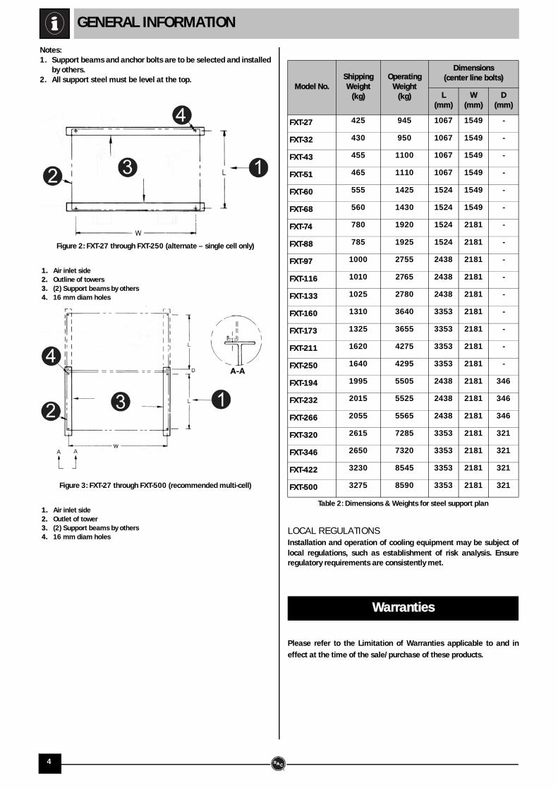
STEEL SUPPORTThe recommended support arrangement for FXT Cooling Towers is 2I-beams running either the length or width of the unit as shown inthe following figures. Besides providing adequate support, the steelalso serves to raise the unit above any solid foundation to assureaccess to the bottom of the tower.FXT towers may also be supported on columns at the anchor boltlocations shown in the following figures, if required. A minimumbearing surface of 15x15 cm must be provided under each of theconcentrated load points.
Leveling
Connecting Pipework
Freeze Protection
Bleed line installation
Safety Precautions
3
GENERAL INFORMATION
Notes:1. Support beams and anchor bolts are to be selected and installed
by others.2. All support steel must be level at the top.
1. Air inlet side 2. Outline of towers 3. (2) Support beams by others 4. 16 mm diam holes
1. Air inlet side 2. Outlet of tower 3. (2) Support beams by others 4. 16 mm diam holes
LOCAL REGULATIONSInstallation and operation of cooling equipment may be subject oflocal regulations, such as establishment of risk analysis. Ensureregulatory requirements are consistently met.
Please refer to the Limitation of Warranties applicable to and in
effect at the time of the sale/purchase of these products.
Figure 2: FXT-27 through FXT-250 (alternate – single cell only)
Figure 3: FXT-27 through FXT-500 (recommended multi-cell)
Model No.ShippingWeight
(kg)
OperatingWeight
(kg)
Dimensions(center line bolts)
L (mm)
W (mm)
D (mm)
FXT-27 425 945 1067 1549 -
FXT-32 430 950 1067 1549 -
FXT-43 455 1100 1067 1549 -
FXT-51 465 1110 1067 1549 -
FXT-60 555 1425 1524 1549 -
FXT-68 560 1430 1524 1549 -
FXT-74 780 1920 1524 2181 -
FXT-88 785 1925 1524 2181 -
FXT-97 1000 2755 2438 2181 -
FXT-116 1010 2765 2438 2181 -
FXT-133 1025 2780 2438 2181 -
FXT-160 1310 3640 3353 2181 -
FXT-173 1325 3655 3353 2181 -
FXT-211 1620 4275 3353 2181 -
FXT-250 1640 4295 3353 2181 -
FXT-194 1995 5505 2438 2181 346
FXT-232 2015 5525 2438 2181 346
FXT-266 2055 5565 2438 2181 346
FXT-320 2615 7285 3353 2181 321
FXT-346 2650 7320 3353 2181 321
FXT-422 3230 8545 3353 2181 321
FXT-500 3275 8590 3353 2181 321
Table 2: Dimensions & Weights for steel support plan
Warranties
4
RIGGING
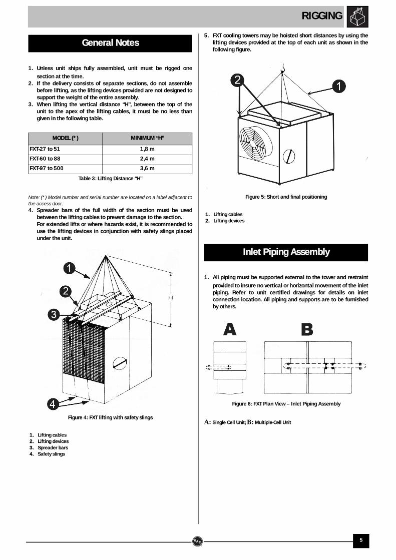
1. Unless unit ships fully assembled, unit must be rigged one
section at the time.2. If the delivery consists of separate sections, do not assemble
before lifting, as the lifting devices provided are not designed tosupport the weight of the entire assembly.
3. When lifting the vertical distance “H”, between the top of theunit to the apex of the lifting cables, it must be no less thangiven in the following table.
Note: (*) Model number and serial number are located on a label adjacent tothe access door.4. Spreader bars of the full width of the section must be used
between the lifting cables to prevent damage to the section. For extended lifts or where hazards exist, it is recommended touse the lifting devices in conjunction with safety slings placedunder the unit.
1. Lifting cables 2. Lifting devices 3. Spreader bars 4. Safety slings
5. FXT cooling towers may be hoisted short distances by using thelifting devices provided at the top of each unit as shown in thefollowing figure.
1. Lifting cables 2. Lifting devices
1. All piping must be supported external to the tower and restraint
provided to insure no vertical or horizontal movement of the inletpiping. Refer to unit certified drawings for details on inletconnection location. All piping and supports are to be furnishedby others.
A: Single Cell Unit; B: Multiple-Cell Unit
General Notes
MODEL (*) MINIMUM “H”
FXT-27 to 51 1,8 m
FXT-60 to 88 2,4 m
FXT-97 to 500 3,6 m
Table 3: Lifting Distance “H”
Figure 4: FXT lifting with safety slings
Inlet Piping Assembly
Figure 5: Short and final positioning
Figure 6: FXT Plan View – Inlet Piping Assembly
5
RIGGING
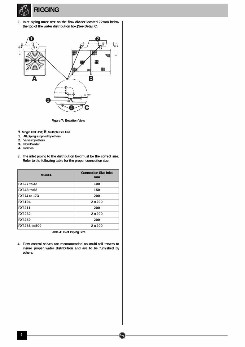
2. Inlet piping must rest on the flow divider located 22mm belowthe top of the water distribution box (See Detail C).
A: Single Cell Unit; B: Multiple Cell Unit 1. All piping supplied by others 2. Valves by others 3. Flow Divider 4. Nozzles
3. The inlet piping to the distribution box must be the correct size.Refer to the following table for the proper connection size.
4. Flow control valves are recommended on multi-cell towers toinsure proper water distribution and are to be furnished byothers.
MODELConnection Size Inlet
mm
FXT-27 to 32 100
FXT-43 to 68 150
FXT-74 to 173 200
FXT-194 2 x 200
FXT-211 200
FXT-232 2 x 200
FXT-250 200
FXT-266 to 500 2 x 200
Table 4: Inlet Piping Size
Figure 7: Elevation View
6
SECTION ASSEMBLY
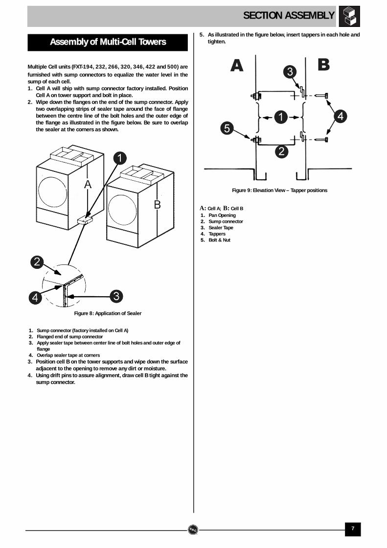
Multiple Cell units (FXT-194, 232, 266, 320, 346, 422 and 500) are
furnished with sump connectors to equalize the water level in thesump of each cell.1. Cell A will ship with sump connector factory installed. Position
Cell A on tower support and bolt in place.2. Wipe down the flanges on the end of the sump connector. Apply
two overlapping strips of sealer tape around the face of flangebetween the centre line of the bolt holes and the outer edge ofthe flange as illustrated in the figure below. Be sure to overlapthe sealer at the corners as shown.
1. Sump connector (factory installed on Cell A) 2. Flanged end of sump connector 3. Apply sealer tape between center line of bolt holes and outer edge of
flange 4. Overlap sealer tape at corners3. Position cell B on the tower supports and wipe down the surface
adjacent to the opening to remove any dirt or moisture.4. Using drift pins to assure alignment, draw cell B tight against the
sump connector.
5. As illustrated in the figure below, insert tappers in each hole andtighten.
A: Cell A; B: Cell B 1. Pan Opening 2. Sump connector 3. Sealer Tape 4. Tappers 5. Bolt & Nut
Assembly of Multi-Cell Towers
Figure 8: Application of Sealer
Figure 9: Elevation View – Tapper positions
7
OPTIONAL ACCESSORIES ASSEMBLY
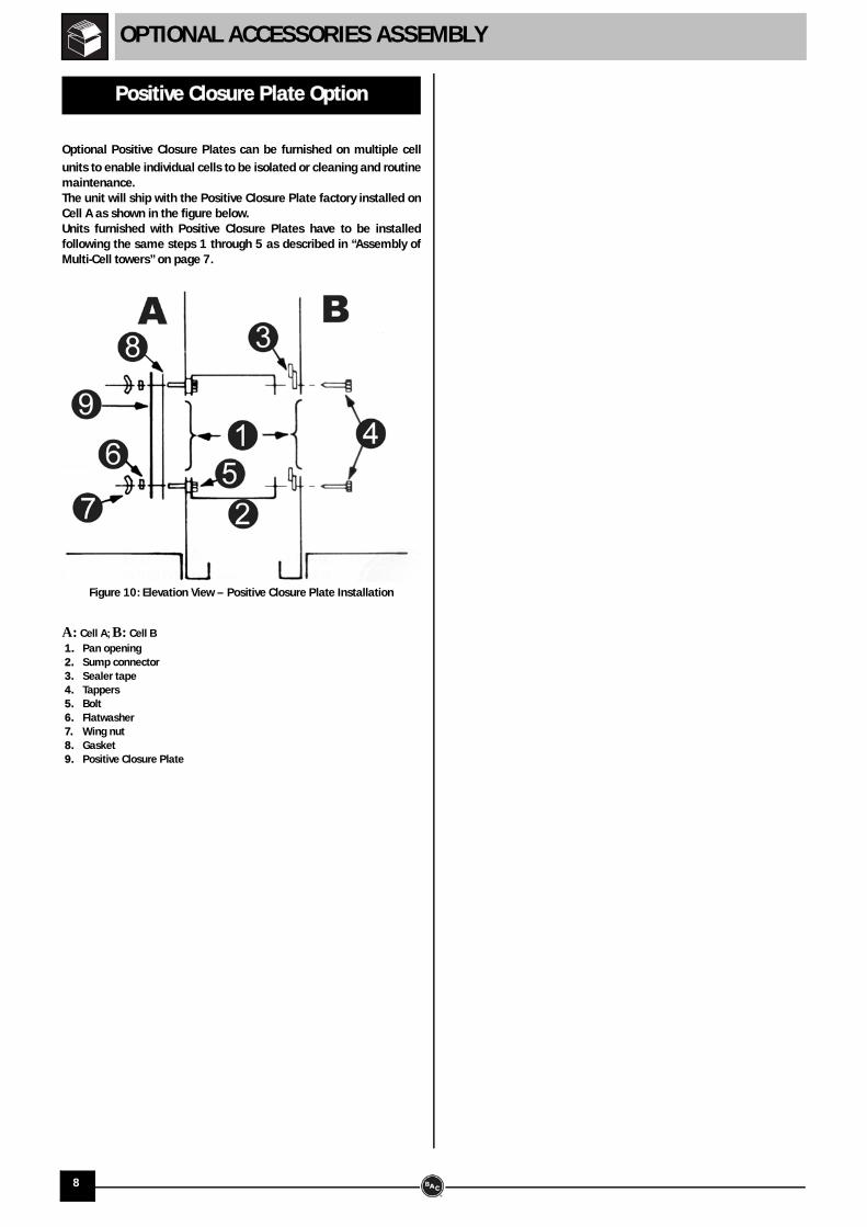
Optional Positive Closure Plates can be furnished on multiple cell
units to enable individual cells to be isolated or cleaning and routinemaintenance.The unit will ship with the Positive Closure Plate factory installed onCell A as shown in the figure below.Units furnished with Positive Closure Plates have to be installedfollowing the same steps 1 through 5 as described in “Assembly ofMulti-Cell towers” on page 7.
A: Cell A; B: Cell B 1. Pan opening 2. Sump connector 3. Sealer tape 4. Tappers 5. Bolt 6. Flatwasher 7. Wing nut 8. Gasket 9. Positive Closure Plate
Positive Closure Plate Option
Figure 10: Elevation View – Positive Closure Plate Installation
8
INSPECTION PRIOR TO START-UP
Prior to start-up, the following services, which are described in detail
in the Operating and Maintenance Manual (see TableRecommended Maintenance and Monitoring Schedule- Start-up)must be performed. Proper start-up procedures and scheduled periodic maintenancewill prolong the life of the equipment and ensure trouble-freeperformance for which the unit is designed.
General
9
10
NOTES
NOTES
11
RECOMMENDED MAINTENANCE AND MONITORING PROGRAMME
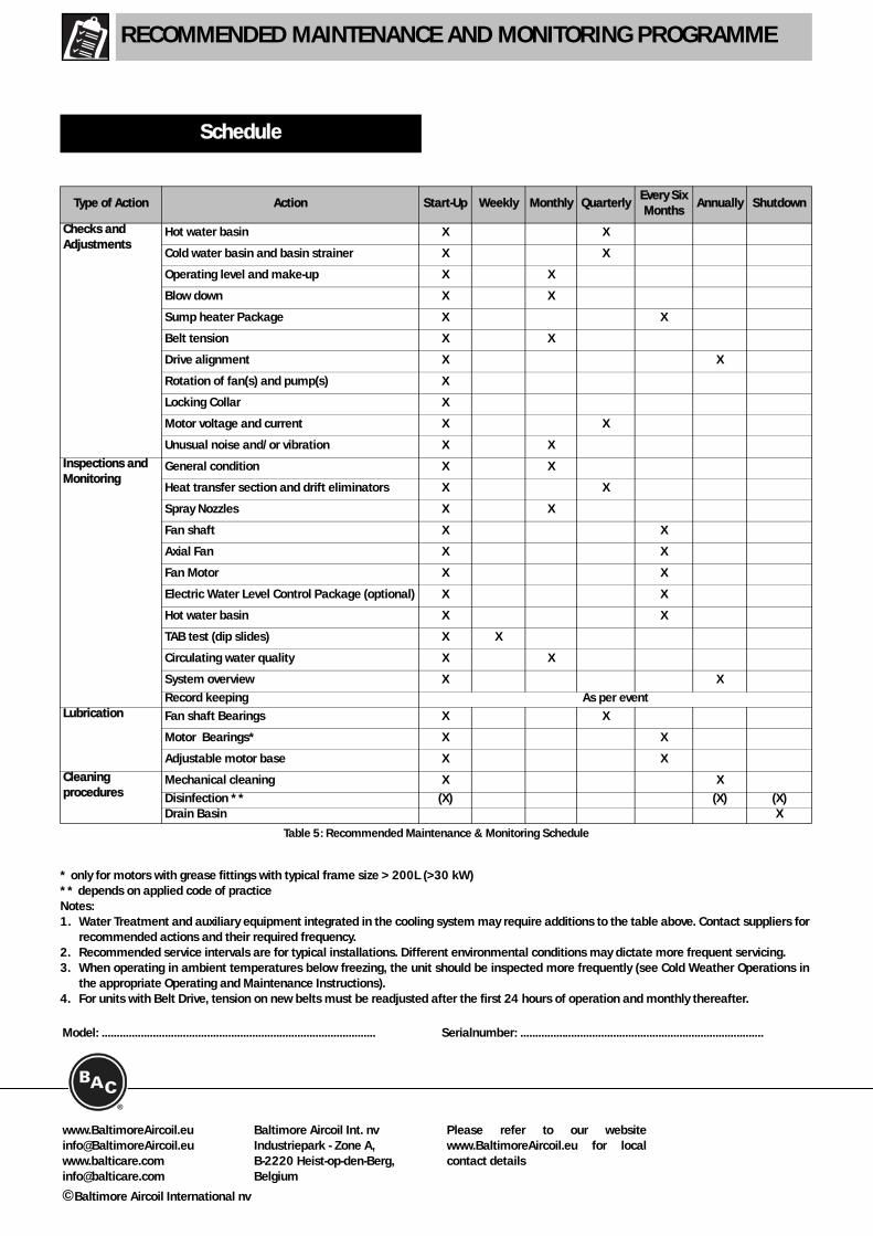
* only for motors with grease fittings with typical frame size > 200L (>30 kW)** depends on applied code of practiceNotes:1. Water Treatment and auxiliary equipment integrated in the cooling system may require additions to the table above. Contact suppliers for
recommended actions and their required frequency.2. Recommended service intervals are for typical installations. Different environmental conditions may dictate more frequent servicing.3. When operating in ambient temperatures below freezing, the unit should be inspected more frequently (see Cold Weather Operations in
the appropriate Operating and Maintenance Instructions).4. For units with Belt Drive, tension on new belts must be readjusted after the first 24 hours of operation and monthly thereafter.
Schedule
Type of Action Action Start-Up Weekly Monthly QuarterlyEvery Six Months
Annually Shutdown
Checks and Adjustments
Hot water basin X X
Cold water basin and basin strainer X X
Operating level and make-up X X
Blow down X X
Sump heater Package X X
Belt tension X X
Drive alignment X X
Rotation of fan(s) and pump(s) X
Locking Collar X
Motor voltage and current X X
Unusual noise and/or vibration X X
Inspections and Monitoring
General condition X X
Heat transfer section and drift eliminators X X
Spray Nozzles X X
Fan shaft X X
Axial Fan X X
Fan Motor X X
Electric Water Level Control Package (optional) X X
Hot water basin X X
TAB test (dip slides) X X
Circulating water quality X X
System overview X X
Record keeping As per eventLubrication Fan shaft Bearings X X
Motor Bearings* X X
Adjustable motor base X X
Cleaning procedures
Mechanical cleaning X X
Disinfection ** (X) (X) (X)Drain Basin X
Table 5: Recommended Maintenance & Monitoring Schedule
www.BaltimoreAircoil.euinfo@[email protected]
Baltimore Aircoil Int. nvIndustriepark - Zone A, B-2220 Heist-op-den-Berg,Belgium
Please refer to our websitewww.BaltimoreAircoil.eu for localcontact details
©Baltimore Aircoil International nv
Model: ........................................................................................... Serialnumber: .................................................................................