rim tach 8500 10 steps to installation · alignment with the sensor ... • inspect c-face, motor...
TRANSCRIPT
Northstar RIM Tach 8500
10 Steps to Installation
K – Wheel (Clamp Style)
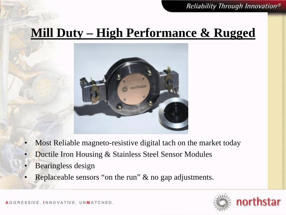
Mill Duty – High Performance & Rugged
• Most Reliable magneto-resistive digital tach on the market today• Ductile Iron Housing & Stainless Steel Sensor Modules• Bearingless design • Replaceable sensors “on the run” & no gap adjustments.
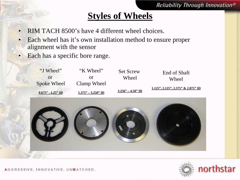
Styles of Wheels• RIM TACH 8500’s have 4 different wheel choices.• Each wheel has it’s own installation method to ensure proper
alignment with the sensor • Each has a specific bore range.
“J Wheel”or
Spoke Wheel0.675” - 1.25” ID
“K Wheel”or
Clamp Wheel1.375” – 3.250” ID
Set Screw Wheel
3.256” – 4.50” ID
End of ShaftWheel
1.125”, 2.125”, 2.375” & 2.875” ID
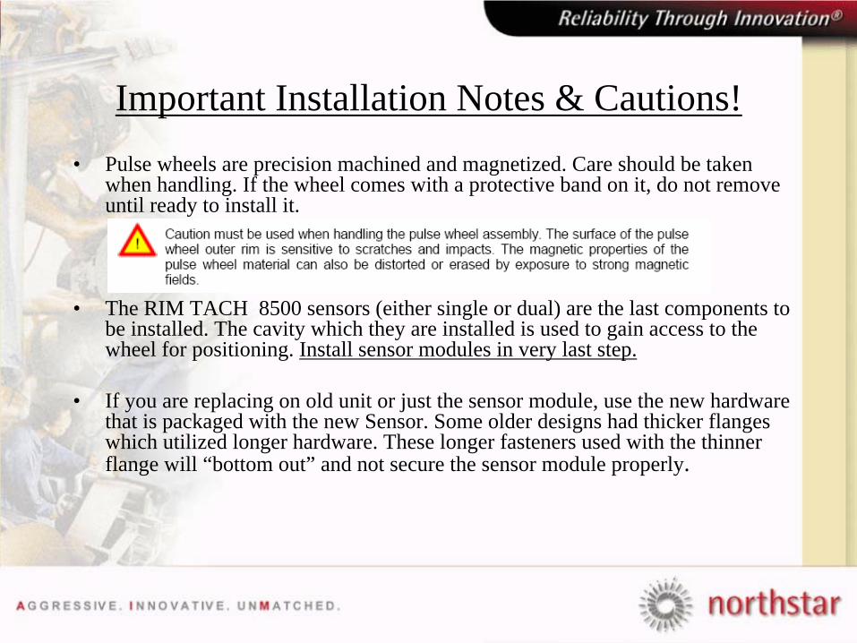
Important Installation Notes & Cautions!• Pulse wheels are precision machined and magnetized. Care should be taken
when handling. If the wheel comes with a protective band on it, do not remove until ready to install it.
• The RIM TACH 8500 sensors (either single or dual) are the last components to be installed. The cavity which they are installed is used to gain access to the wheel for positioning. Install sensor modules in very last step.
• If you are replacing on old unit or just the sensor module, use the new hardware that is packaged with the new Sensor. Some older designs had thicker flanges which utilized longer hardware. These longer fasteners used with the thinner flange will “bottom out” and not secure the sensor module properly.
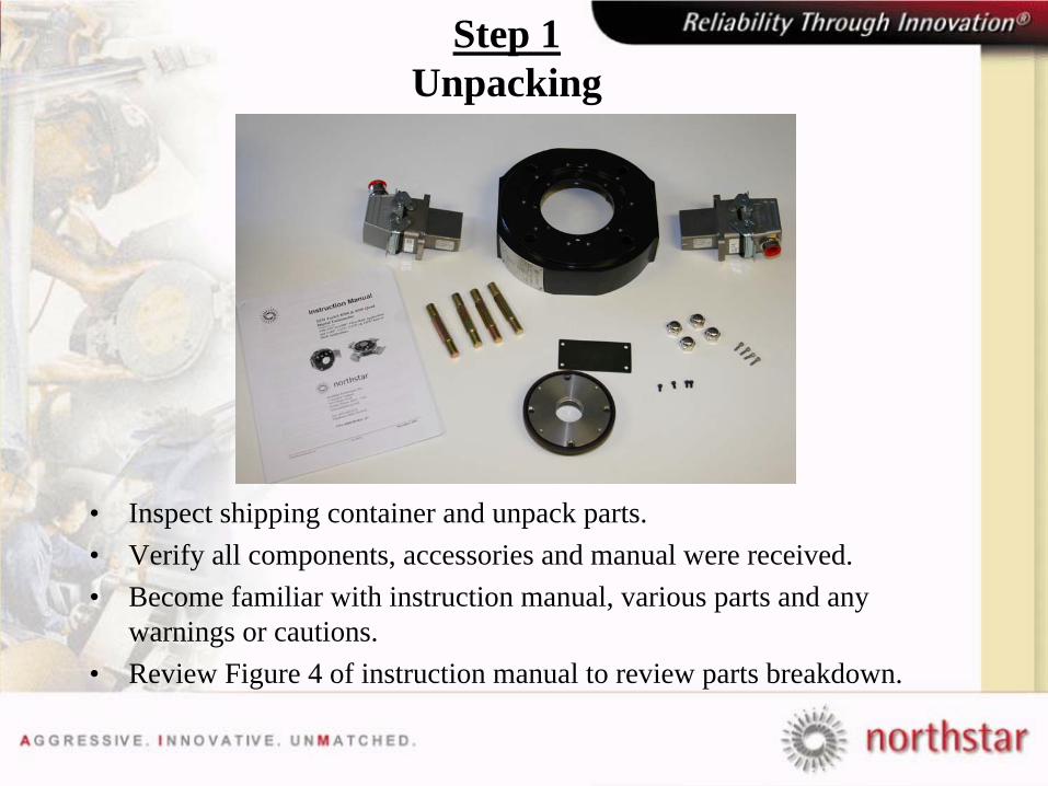
Step 1 Unpacking
• Inspect shipping container and unpack parts.• Verify all components, accessories and manual were received.• Become familiar with instruction manual, various parts and any
warnings or cautions.• Review Figure 4 of instruction manual to review parts breakdown.
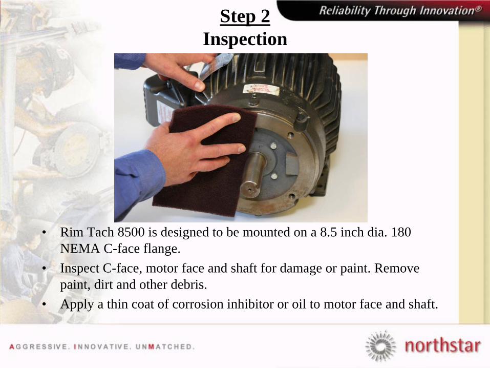
Step 2 Inspection
• Rim Tach 8500 is designed to be mounted on a 8.5 inch dia. 180 NEMA C-face flange.
• Inspect C-face, motor face and shaft for damage or paint. Remove paint, dirt and other debris.
• Apply a thin coat of corrosion inhibitor or oil to motor face and shaft.

Step 3 Insert mounting Studs
• Insert (4) ½-12 plated mounting studs into the motor frame.• Torque to a nominal 60 Ft-lbs.
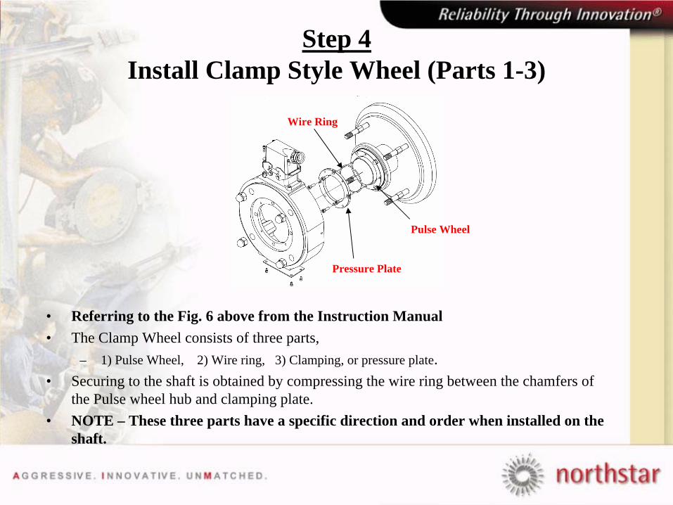
Step 4 Install Clamp Style Wheel (Parts 1-3)
• Referring to the Fig. 6 above from the Instruction Manual• The Clamp Wheel consists of three parts,
– 1) Pulse Wheel, 2) Wire ring, 3) Clamping, or pressure plate.• Securing to the shaft is obtained by compressing the wire ring between the chamfers of
the Pulse wheel hub and clamping plate.• NOTE – These three parts have a specific direction and order when installed on the
shaft.
Pressure Plate
Pulse Wheel
Wire Ring
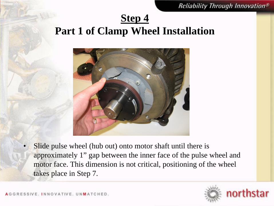
Step 4 Part 1 of Clamp Wheel Installation
• Slide pulse wheel (hub out) onto motor shaft until there is approximately 1” gap between the inner face of the pulse wheel and motor face. This dimension is not critical, positioning of the wheel takes place in Step 7.
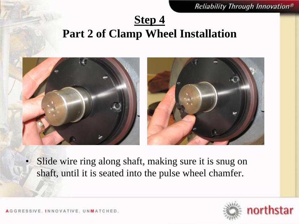
Step 4 Part 2 of Clamp Wheel Installation
• Slide wire ring along shaft, making sure it is snug on shaft, until it is seated into the pulse wheel chamfer.
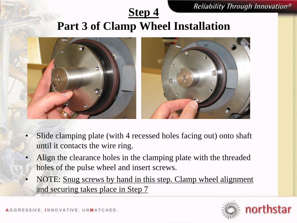
Step 4 Part 3 of Clamp Wheel Installation
• Slide clamping plate (with 4 recessed holes facing out) onto shaft until it contacts the wire ring.
• Align the clearance holes in the clamping plate with the threaded holes of the pulse wheel and insert screws.
• NOTE: Snug screws by hand in this step. Clamp wheel alignment and securing takes place in Step 7
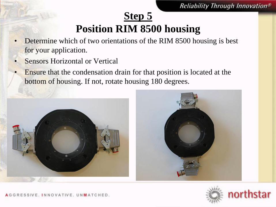
Step 5 Position RIM 8500 housing
• Determine which of two orientations of the RIM 8500 housing is best for your application.
• Sensors Horizontal or Vertical• Ensure that the condensation drain for that position is located at the
bottom of housing. If not, rotate housing 180 degrees.
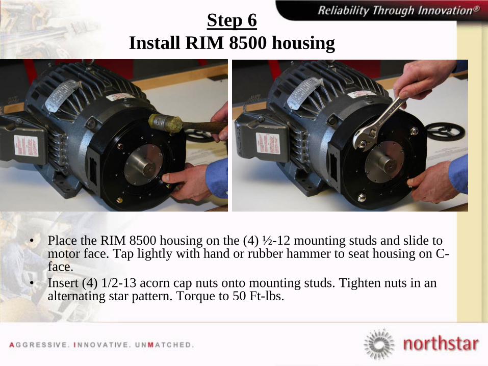
Step 6 Install RIM 8500 housing
• Place the RIM 8500 housing on the (4) ½-12 mounting studs and slide to motor face. Tap lightly with hand or rubber hammer to seat housing on C- face.
• Insert (4) 1/2-13 acorn cap nuts onto mounting studs. Tighten nuts in an alternating star pattern. Torque to 50 Ft-lbs.
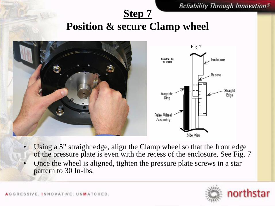
Step 7 Position & secure Clamp wheel
• Using a 5” straight edge, align the Clamp wheel so that the front edge of the pressure plate is even with the recess of the enclosure. See Fig. 7
• Once the wheel is aligned, tighten the pressure plate screws in a star pattern to 30 In-lbs.
Fig. 7
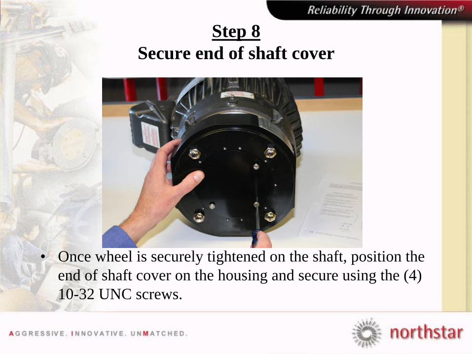
Step 8 Secure end of shaft cover
• Once wheel is securely tightened on the shaft, position the end of shaft cover on the housing and secure using the (4) 10-32 UNC screws.
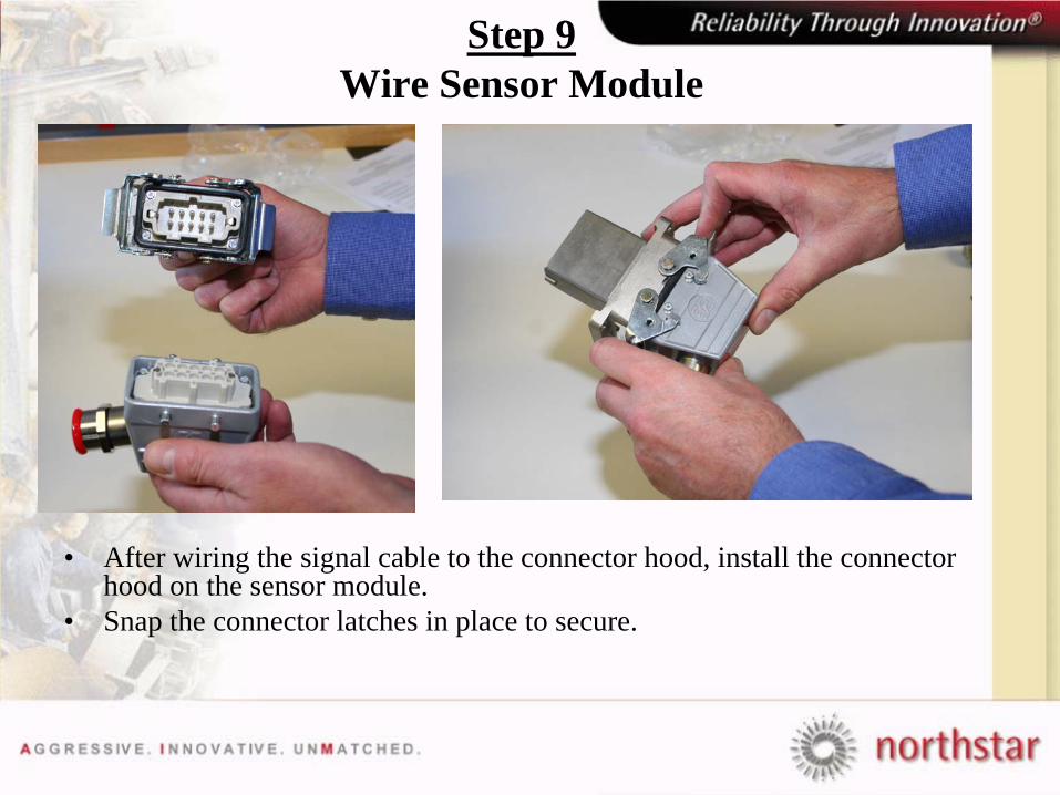
Step 9 Wire Sensor Module
• After wiring the signal cable to the connector hood, install the connector hood on the sensor module.
• Snap the connector latches in place to secure.
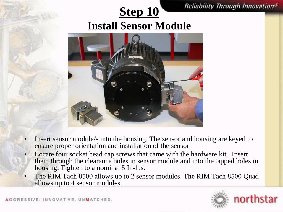
Step 10 Install Sensor Module
• Insert sensor module/s into the housing. The sensor and housing are keyed to ensure proper orientation and installation of the sensor.
• Locate four socket head cap screws that came with the hardware kit. Insert them through the clearance holes in sensor module and into the tapped holes in housing. Tighten to a nominal 5 In-lbs.
• The RIM Tach 8500 allows up to 2 sensor modules. The RIM Tach 8500 Quad allows up to 4 sensor modules.

Complete RIM Tach 8500
•Other training modules available•RIM Tach 8500 “End-of-Shaft Wheel”•RIM Tach 8500 “J Wheel”•RIM Tach “Shaft Grounding Brush”