road planning and design manual - 1st edition - chapter 6 - …/media/busind/techstdpubs/road... ·...
TRANSCRIPT

Department of Main Roads Chapter 6 Road Planning and Design Manual Speed Parameters
November 2007
i
6
Chapter 6 Speed Parameters

Department of Main Roads Chapter 6 Road Planning and Design Manual Speed Parameters
November 2007
ii
6
Manual Contents
Chapter 1 Framework of the Road Planning and
Design Manual
Chapter 13 Intersections at Grade
Chapter 2 Design Philosophy
Chapter 14 Roundabouts
Chapter 3 Road Planning and Design Fundamentals
Chapter 15 Auxiliary Lanes
Chapter 4 Application of Design Principles and
Guidelines
Chapter 16 Interchanges
Chapter 5 Traffic Parameters and Human Factors
Chapter 17 Lighting
Chapter 6 Speed Parameters
Chapter 18 Traffic signals
Chapter 7 Cross Section
Chapter 19 Intelligent Transport Systems
Chapter 8 Safety Barriers and Roadside Furniture
Chapter 20 Roadside Amenities
Chapter 9 Sight Distance
Chapter 21 Railway and Cane Railway Level
Crossings
Chapter 10 Alignment Design
Chapter 22 Bridges, Retaining Walls
Chapter 11 Horizontal Alignment
Chapter 23 Tunnels
Chapter 12 Vertical Alignment

Department of Main Roads Chapter 6 Road Planning and Design Manual Speed Parameters
November 2007
iii
6
Table of Contents Manual Contents .............................................................................................. ii
Table of Contents ............................................................................................ iii
Chapter 6 Amendments - November 2007...................................................... v
Revision Register ............................................................................................. v
6.1 Introduction.......................................................................................... 6-1
6.1.1 Background............................................................................................6-1
6.1.2 Speed Prediction Models .......................................................................6-1
6.1.3 Definitions / Explanation of Key Terms ..................................................6-2
6.2 Warrants for Geometric Assessment ................................................ 6-6
6.3 Operating Speed Characteristics and Geometric Standard of Different Road Types – Including Determination of Desired Speed ......... 6-6
6.3.1 Rural Roads ...........................................................................................6-6
6.3.2 Motorways and Interchange Ramps ....................................................6-11
6.3.3 Urban Roads ........................................................................................6-12
6.3.4 Temporary Roads (including sidetracks)..............................................6-13
6.4 Determination of Design Speeds ..................................................... 6-15
6.4.1 Roads on which Vehicle Speeds are Largely Unaffected by the Horizontal Alignment .........................................................................................................6-15
6.4.2 Roads on which Vehicle Speeds are Largely Influenced by the Horizontal Alignment .........................................................................................................6-16
6.4.3 Truck Speeds .......................................................................................6-17
6.5 Driver Behaviour and Road Design ................................................. 6-18
6.6 Potential Relative Speed Between Vehicles.................................... 6-19
6.6.1 Definition ..............................................................................................6-19
6.6.2 Design Principles .................................................................................6-19
6.7 Decrease in Speed Between Successive Elements........................ 6-20
6.7.1 Definition ..............................................................................................6-20
6.7.2 Maximum Decrease in Speeds Between Successive Elements of Roadways.........................................................................................................6-20
6.7.3 Maximum Increase in Side Friction Between Successive Elements of Roadways.........................................................................................................6-20

Department of Main Roads Chapter 6 Road Planning and Design Manual Speed Parameters
November 2007
iv
6
6.8 Speed Parameters in the Design Process....................................... 6-22
6.8.1 Select Target Speed/s..........................................................................6-22
6.8.2 Determine Trial Horizontal and Vertical Alignment ..............................6-23
6.8.3 Determine Desired Speed/s .................................................................6-23
6.8.4 Check Desired Speed against Target Speed.......................................6-23
6.8.5 Determine Operating Speeds / Design Speeds ...................................6-23
6.8.6 Relative Speed Checks........................................................................6-25
6.8.7 Complete Vertical Alignment and Review Horizontal Alignment..........6-26
6.9 Using the Operating Speed Model ................................................... 6-26
6.9.1 Basic Concepts ....................................................................................6-26
6.9.2 Operating Speed Model Components..................................................6-27
6.9.3 Using the Operating Speed Model .......................................................6-29
6.9.4 Additional considerations when using the Operating Speed Model .....6-39
6.9.5 Effects of Grades .................................................................................6-40
6.9.6 Effect of Cross-Section ........................................................................6-40
6.9.7 Effect of Pavement Condition...............................................................6-41
References................................................................................................... 6-42
Relationship to Other Chapters ................................................................. 6-43
Appendix 6A: Example of Applying the Operating Speed Model........... 6-44
Appendix 6B: Operating Speeds on Long Grades Steeper than 5% ..... 6-61
Appendix 6C: Symbols used in this Chapter ........................................... 6-62

Department of Main Roads Chapter 6 Road Planning and Design Manual Speed Parameters
November 2007
v
6
Chapter 6 Amendments - November 2007
Revision Register
Issue/
Rev
No.
Reference
Section
Description of Revision Authorised
by
Date
1 - First Issue Steering
Committee
Nov
2000
2 All Total revision to replace Speed Environment
Model with Operating Speed Model
Steering
Committee
6 Nov
2007
6

Department of Main Roads Chapter 6 Road Planning and Design Manual Speed Parameters
November 2007
vi
6

Department of Main Roads Chapter 6 Road Planning and Design Manual Speed Parameters
November 2007
6-1
6
Chapter 6
Speed Parameters 6.1 Introduction
6.1.1 Background
A fundamental aim of geometric road design is to provide road geometry (e.g. curvature, sight distance, superelevation etc.) that is suitable for the speeds that most vehicles operate at on the road. The actual operating speeds of vehicles can vary with time due to changes in traffic conditions and from point to point due to changes in the road environment, road characteristics, speed limits, driver behaviour and vehicle types.
Australian research in the late 1970’s (McLean 1977) showed that on roads of consistently high geometric standard (i.e. ones where all of the geometric elements are designed for more than 100km/h, operating speeds on horizontal curves and straights are not significantly different and typically do not exceed 110km/h. As explained in Section 6.2, these roads are called high-speed roads.
However, on most rural roads with geometric elements designed for speeds of 100km/h or less, McLean (1977) found that operating speeds vary over the length of the road. Higher speeds will occur on straights and large radius horizontal curves than on the more typical horizontal curves. As explained later, these roads are called intermediate speed roads or low speed roads, depending upon the operating speeds. On roads of this type that were designed and built prior to the introduction of the Austroads Speed Environment Model
in 1980 (NAASRA 1980), it was common for the operating speed on straights and large radius curves to exceed the design speed of those elements with the result that many of the other curves were also overdriven. Prior to the Speed Environment Model, a single design speed was assumed for ‘significant lengths’ of road, with the design speed being influenced by what could be achieved on the more constrained sections of the road.
The research that led to the development of the Austroads Speed Environment Model showed that drivers mainly react to visible cues or hazards and the principal visible cues that drivers use to set their speed are the apparent horizontal curvature of the road ahead and the roadside environment. Drivers react much less to vertical curvature and to a potential hazard that is out of view, e.g. beyond a crest vertical curve, even though attention may be drawn to the hazard by signs or other devices. In other words, vertical geometry and available sight distance have little effect on the speed adopted by drivers. It is the horizontal geometry and the topography that have the greatest effect.
6.1.2 Speed Prediction Models
The Speed Environment Model predicted the speed along a road where the operating speed varied. Its introduction provided a fundamental change in the way these roads were designed. Proper use of the model allowed these roads to be designed so that they closely matched the way they were driven. In contrast, the previous ‘single

Department of Main Roads Chapter 6 Road Planning and Design Manual Speed Parameters
November 2007
6-2
6
design speed’ approach essentially assumed motorists would drive the road according to the design speed.
However, the Speed Environment Model was not well implemented in Australia. This was largely due to its complexity and subjective elements with certain types of road. This is explained further in Cox (2003). Consequently, in 2003, Austroads adopted the Operating Speed Model (originally developed by VicRoads, see VicRoads (1994)) because it overcame some of the limitations of the Speed Environment Model. The Operating Speed Model was developed from the Speed Environment Model and the same research data that led its development. Validation of the Operating Speed Model was undertaken by the Australian Road Research Board (ARRB), see Botterill (1994).
Main Roads has subsequently adopted the Operating Speed Model with some minor enhancements as described in Section 6.9.
6.1.3 Definitions / Explanation of Key Terms
In order to produce a logical basis for the selection of speeds for geometric design, it is necessary to define and explain six key terms:
1. Target Speed.
2. Operating Speed / 85th Percentile Speed.
3. Desired Speed.
4. Design Speed.
5. Limiting Curve Speed.
6. Geometric Standard.
These terms are defined in the following paragraphs. Section 6.7.3 describes how each of these terms fit into the process for
the design of a horizontal alignment. Appendix 6A provides a comprehensive example on the application of this process.
Target Speed
Target speed is the indicative operating speed for a road link (or a significant part of the road link). It is set at the network planning level to meet an expected level of operational performance. It establishes a target geometric design standard for the road link that is commensurate with the function of the road, anticipated funding levels, community expectations etc. However, the road link is not always designed to the target speed over its entire length as there can be sections of road where it is not practical to provide road geometry that matches the target speed. For an overview of how target speed relates to other speed terms, see Figure 6.1.3. Selection of target speed is covered in Chapter 4 (Application of Design Principles and Guidelines).
Operating Speed / 85th Percentile Speed
Operating speed is the eighty-fifth (85th) percentile speed at some point on the road.
In turn, the 85th percentile speed is the speed at, or below which 85% of cars are observed to travel under free flowing conditions past a nominated point. Eighty-five percent of car drivers will travel at or below this speed and 15% will travel faster. Free flowing conditions occur when the traffic volume is small enough to afford the higher levels of service capable of being provided by the road. The times or periods of free flowing conditions can be readily identified from the reports produced from traffic counters that record both speed and volume for hourly (or less) periods

Department of Main Roads Chapter 6 Road Planning and Design Manual Speed Parameters
November 2007
6-3
6
throughout the day. On a low volume rural road, free flowing conditions occur throughout the day. On a high volume urban road, free flowing conditions will occur sometime prior to the morning peak and after the evening peak. It may also occur between the peaks. For an overview of how operating speed relates to other speed terms, see Figure 6.1.3.
Speed distribution curves from many sites around the country, show that the 85th percentile speed represents the point where increases in speed value cater for a rapidly diminishing proportion of drivers.
In effect, this means that designs based on the 85th percentile speed (i.e. operating speed) will cater for the majority of drivers. For design purposes, the 15% of drivers who exceed this speed are considered to be aware of the increased safety risk they are taking and are expected to maintain a higher level of alertness, effectively reducing their reaction times. It is not possible for practical reasons (mainly economic) for any road authority to design a road based on the 100th percentile speed.
Determination of operating speed on each element of a particular horizontal alignment design is discussed in Section 6.4.
It is important to note is that on a two way road, operating speed may be different for each direction of travel. Furthermore, on a multi-lane carriageway, operating speed may vary from lane to lane. However use of this particular characteristic would only be needed in exceptional circumstances.
Desired Speed
This is the operating speed that drivers will adopt on the less constrained elements, i.e. straights and large radius horizontal curves of a reasonably uniform section of road
when not constrained by other vehicles. For an overview of how desired speed relates to other speed terms, see Figure 6.1.3.
The desired speed for a section of road is influenced by:
Roadside Environment - topography in rural areas, development density and type (i.e. built environments) in urban areas.
Road Characteristics - geometric standard (predominately horizontal alignment; to a lesser extent, vertical alignment; and lane widths), frequency of intersections and accesses, sight distance, parking provisions etc.
Speed Limit.
Road Function – to the extent that on important roads such as motorways and highways, drivers are less willing to accept reductions in desired speed.
On intermediate and low speed rural roads (see Section 6.3.1) with 100km/h speed limits, the principal factors controlling the desired speed are the topography and horizontal alignment. All other factors listed above only have a secondary effect. On motorways and rural roads with a high geometric standard, the speed limit primarily influences the desired speed, particularly if regular enforcement is provided. On urban arterial roads, the primary factors influencing the desired speed are the roadside environment and the speed limit, since these will usually limit desired speed before the standard of the horizontal alignment.
In practice, the desired speed is often about 10km/h above the posted speed limit. Main Roads has large amounts of speed data that show this.

Department of Main Roads Chapter 6 Road Planning and Design Manual Speed Parameters
November 2007
6-4
6
Desired speed does not vary over a section of roadway that has a similar roadside environment, road characteristics and speed limit but the section may still have isolated geometric features inconsistent with the desired speed. Isolated geometric features can include the following:
a “tight” horizontal curve (or a short section of road containing a few “tight” curves);
an intersection controlled by a stop or give-way sign;
a roundabout; or
an overtaking lane / climbing lane.
In the case of an overtaking lane, it is possible that the operating speed of the overtaking lane will exceed the desired speed for the section of road.
If the roadside environment, road characteristics and speed limit of the roadway are similar before and after the isolated feature, the desired speed will remain the same. The desired speed will only change if the roadside environment or road characteristics change over a significant length of roadway.
Typically, reductions in desired speed take longer to come into effect than increases in desired speed. Therefore, on two-way roads, there may be locations where the desired speed is different for each direction (see Figure 6.1.3).
The Operating Speed Model does not explicitly encompass the concept of desired speed. In fact, in its basic form, it uses an implicit desired speed of 110km/h for all roads. Although this will be the case with most intermediate speed roads and even some low speed rural roads, there will be times a lower desired speed should be taken into account (see Section 6.2).
With the previous Speed Environment Model, Speed Environment was a measure of the influence that various factors have on the desired speed of drivers on significant lengths of the road. Therefore, Speed Environment is numerically equal to Desired Speed. Although the term speed environment is not used in conjunction with the Operating Speed Model, the concept is still valid since it effectively equates to desired speed. It is likely to remain in general usage for some time.
Design Speed
Design speed is defined as the speed that is adopted for the calculation of the various geometric design parameters (e.g. sight distance, application of superelevation, vertical curve radii). Design speed must be equal to or greater than the operating speed (85th percentile speed) for the particular horizontal geometric element. For an overview of how design speed relates to other speed terms, see Figure 6.1.3.
Determination of Design Speed is discussed in Sections 6.2 and 6.4.
Limiting Curve Speed
The limiting curve speed is the speed at which a vehicle travelling on a curve of given radius and superelevation, will have a side friction demand equal to the absolute maximum recommended value given in Chapter 11 (Horizontal Alignment), for that speed. The operating speed on a particular horizontal curve should not exceed the limiting curve speed for that curve. It may not be possible to apply this criterion, however, for horizontal curves on the minor roads at intersections, intersection turns and on roundabouts. On some interchange off-ramps and connecting ramps, it will be common for some curves to be driven at

Department of Main Roads Chapter 6 Road Planning and Design Manual Speed Parameters
November 2007
6-5
6
close to the limiting curve speed. This is due to general driver behaviour expectations and familiarity with these facilities. The Operating Speed model will show when this occurs.
Except for intersection turns and connecting roadways in interchanges, horizontal curve radii approaching the limiting curve speed radius should only be used in very constrained situations where dictated by economics or having to retain existing curvature. Such cases must be supported by factors that would ensure that the curves are consistent with driver expectations.
The limiting curve speed is also used as a secondary check on geometric consistency when the primary check between successive
elements is greater than the desirable limit but less than the absolute limit See Section 6.7.2 and Appendix 6A.
Geometric Standard
Within this Chapter, the term geometric standard simply serves as a comparison of the capability of different road alignments. For example, a high geometric standard permits high operating speeds and provides a higher level of service for a given traffic volume under free flowing conditions; a low geometric standard would result in low operating speeds and probably a lower level of safety. The term is not intended to determine some level of conformance to a prescribed standard.
Figure 6.1.3 General Overview of Speed Relationships
VTarget (say 110km/h)
Target Speed (VTarget) sets the Preferred Design Standard for a road link. Usually set at a strategic level. Actual design speed/s depend on the operating speed/s along the road in each direction. Note that it is possible for the
operating speed to exceed the Target Speed in some places and to be less than the Target Speed in other places.
VDesired = 110 km/h
VDesign [VOperating = 85th Percentile Speed (V85)]
Operating Speed (VOperating) is the 85th percentile speed at a point along the road, relative to the direction and lane of travel. Can be either measured on existing roads or predicted using the Operating Speed Model for existing or
new roads. Operating Speed can vary along the road / between geometric elements depending on road type.
Desired Speed (VDesired) is the operating speed on the longer straights and larger curves over a significant section of road, relative to direction and lane of travel. Influenced by several factors and may or may not be the same across all
sections of a road link.
100 km/h
88 km/h
110 km/h
94 km/h
VDesired = 100 km/h VDesired = 110 km/h VDesired = 100 km/h
VDesired = 100 km/h
98 km/h
105 km/h
100 km/h
90 km/h
100 km/h
88 km/h
94 km/h
Important: This figure is to be read in conjunction with the definitions given within this chapter.
Design Speed (VDesign) for the calculation of various geometric design parameters is equal to or greater than the Operating Speed for the particular horizontal geometric element the parameter is within.

Department of Main Roads Chapter 6 Road Planning and Design Manual Speed Parameters
November 2007
6-6
6
6.2 Warrants for Geometric Assessment
Essential to understanding whether a road project is “fit for purpose” or a “context sensitive design” is an assessment of its geometry (Cox and Foley 2003 – see also Chapter 2 (Design Philosophy)). Also, it is not just new road alignments that require an assessment of the operating speeds and the road geometry. Chapter 4 (Application of Design Principles and Guidelines) explains how the design of many types of restoration projects (which mostly retain an existing alignment) must include a geometric assessment of the alignment. This is because these projects have the potential to change driver perception of the road with a consequent increase in operating speed. In turn, some geometric features may not be suitable for the higher operating speed. The geometric assessment will show if this is the case.
6.3 Operating Speed Characteristics and Geometric Standard of Different Road Types – Including Determination of Desired Speed
Whereas the target speed for a road sets the overall expected geometric standard of a road (or major section of the road) and helps ensure design consistency, there can be sections of the road where it is not practical to provide road geometry that matches the target speed. As long as there are factors that help moderate the desired speed (see previous explanation of desired speed), it is acceptable to have sections of the road where the geometric standard or
desired speed is less than the target speed. As will be seen, there will also be factors that make it more acceptable for the desired speed to be less than the target speed on some types of road than it is for other types.
It should also be realised that it is possible to have a section of road where the desired speed exceeds the target speed. This is more likely to occur through a fortuitous combination of terrain and large radius horizontal curves.
6.3.1 Rural Roads
General
Rural roads range from rural motorways, highways and arterials down to rural district or local roads. Chapter 4 (Application of Design Principles and Guidelines) describes how these road types fit the State Road Network classifications. Compared with urban roads, the desired speed for a section of rural road is largely influenced by the horizontal geometry of the road.
A rural road carrying a large volume of traffic will usually have a higher target speed (and hence geometric standard and desired speed) than a road of lesser importance in similar topography; particularly where the savings in vehicle operation and other costs are sufficient to offset the increased costs of resumption, construction and access. A road in level or easy undulating country will usually have a higher geometric standard (and desired speed) than a road with similar traffic volume in more rugged country.
Where there is an obvious reason for a lower standard of geometry (e.g. rugged or steep terrain), drivers expect to travel at lower speeds and are more prepared to adjust to lower standard geometry than where there is no apparent reason for it.

Department of Main Roads Chapter 6 Road Planning and Design Manual Speed Parameters
November 2007
6-7
6
Drivers recognise or sense a logical speed for road conditions based on their knowledge of the system and appraisal of the ruggedness of the terrain, which they subconsciously relate to the road and its quality. Drivers do not adjust their speeds to the function or classification of the road, but to the physical limitations and the prevailing traffic conditions. However, on more important roads, drivers are likely to be less willing to accept sections of lower standard geometry, especially if the section is not long enough to have drivers feel that their desired speed is no longer appropriate.
Regardless of functional classification, rural roads can be classed in terms of their general operating characteristics as:
High Speed Rural Roads;
Intermediate Speed Rural Roads; or
Low Speed Rural Roads.
High Speed Rural Roads
These are roads that are designed for operating speeds in excess of 100km/h (see Figure 6.3.1(a). On these high-speed roads, operating speeds are not constrained by the largely consistent geometry of the road but by a number of other factors, which include:
The degree of risk the drivers are prepared to accept;
Speed limits and the level of policing of these limits; and
Vehicle performance.
These roads have a high desired speed and a uniform operating speed. Consequently they can (and should) have a single design speed.
Figure 6.3.1(a) Example of a high speed
rural road
Intermediate Speed Rural Roads
These are roads designed with minimum operating speeds (in places) of about 80km/h (see Figure 6.3.1(b). Operating speeds on these roads are generally constrained by the geometry. Drivers will, however, accelerate whenever the opportunity arises, such as on any straight or large radius curve. Speeds will increase up to the desired speed where possible, which may be up to 110km/h. Curve radii on these roads are generally in excess of 160m. The speed limit is likely to be 80km/h to 100km/h.
Figure 6.3.1(b) Example of an
intermediate speed rural road

Department of Main Roads Chapter 6 Road Planning and Design Manual Speed Parameters
November 2007
6-8
6
Low Speed Rural Roads
These are roads having many curves with radii less than 150m. Operating speeds on the curves generally vary from 50km/h to 70km/h (see Figure 6.3.1(c). Rural roads usually only have these characteristics when difficult terrain and costs preclude the adoption of higher standard geometry. The alignments provided in these circumstances could be expected to produce a high degree of driver alertness, so those lower standards are both expected and acceptable. These roads often have a reduced speed limit (typically 60km/h) which also helps lower the desired speed.
The most pragmatic approach to the design of individual elements in such constrained situations is to provide the best curvature that appears practicable, and to check that it is within the absolute minimum standards for the operating speed. Innovative, non-standard treatments will often be required when these standards cannot be met.
Figure 6.3.1(c) Example of a low speed
rural road
Determining Desired Speed on Existing Rural Roads
For restoration projects on existing rural roads, or for short sections that are being realigned, operating speeds should be measured from speed studies on suitable sections of the existing road. The desired
speed may be measured directly as the 85th percentile speed on long straights or large radius horizontal curves where there has been sufficient length for drivers to maintain a constant speed to suit the surrounding terrain. Typically, this length needs to be at least:
300m – where 70km/h is desired speed;
450m – where 90km/h is desired speed;
600m – where 110km/h is desired speed.
With restoration projects, it is also necessary to account for any increase in operating speed due to the improved cross section and riding quality. Sections 6.9.6 and 6.9.7 give suitable guidance.
Even if it is not possible to measure speeds at a location where the operating speed matches the desired speed, the measured operating speeds can still be used as a check for the speeds predicted by the Operating Speed Model. If the predicted operating speed is close to the measured speed at that point, any assumptions about initial speeds, desired speed and the effect of grade on speed increase will be confirmed.
Often, speed data is readily available from traffic counters that measure other aspects including volume and composition. These traffic counters however, may not distinguish between cars and heavy vehicles or between free vehicles and constrained vehicles. If speed data is not available, a desired speed may be selected as shown for new roads. However, actual speed data does remove some of the uncertainty and consequent need for iteration that may exist in the process for new roads.
Alternatively, if a similar road exists nearby (e.g. similar topography, horizontal curvature, road function), speed data

Department of Main Roads Chapter 6 Road Planning and Design Manual Speed Parameters
November 2007
6-9
6
collected on it may be used to provide an indication of the likely desired speed on the existing road being considered.
Determining Desired Speed on New Rural Roads
Where a similar roadside environment and horizontal geometry exist over a long length of road, drivers usually have the same desired speed over the entire length. This makes it easier to ensure that a consistent standard of geometry is provided along the full length of the road. This does not necessarily mean though that operating speeds will be uniform unless the road is being designed as a high-speed road.
When realigning a section within the total length of an intermediate or low-speed road, the assessment of the desired speed should also take into account the curvature on at least 1.5km of the road beyond each end of the realignment. If the adjoining sections are likely to be upgraded in the future, the analysis of desired speed must also cover the short term and long term scenarios.
Table 6.3.1(a) can be used as a guide when selecting the desired speed and hence design speed for rural roads with high standard geometry. Such roads provide a high quality of service for all drivers and, except for exceptional constraints, all geometric elements have a uniform design speed. Normally, high speed roads are used:
Where the high standard geometrics are compatible with the terrain, or
Where the importance of the road justifies the additional costs of achieving the added quality of service.
For low and intermediate speed rural roads, the desired speed can be determined from
Table 6.3.1(b) using the general range of curve radii that are likely to be adopted. However, if these roads are to be speed zoned (i.e. have a speed limit less than 100km/h) the desired speed will typically be equal to the speed limit plus 10km/h.
If a similar road exists nearby (e.g. similar topography, horizontal curvature, road function), speed data collected on it may be used to provide an indication of the likely desired speed on the new road being considered.
Desired Speed on Steep Grades
On steep grades, it is necessary to minimise the potential relative speeds of the faster lighter vehicles and the slower heavier vehicles in order to minimise rear-end accident rates. Such grades usually occur in mountainous terrain. The hatched area of Figure 6.3.1(d) shows combinations of roadway slope and length where the design should aim to achieve a relatively low desired speed (recommended maximum 80km/h). The horizontal geometry should be used to limit the desired speed in order to minimise the potential relative speeds. See also the example in Appendix 6B and Section 6.7.3.

Department of Main Roads Chapter 6 Road Planning and Design Manual Speed Parameters
November 2007
6-10
6
Figure 6.3.1 (d) Identification of Roadways on Long, Steep Grades
Table 6.3.1(a) Typical Desired Speed (for roads on which vehicle speeds are largely
unaffected by the horizontal alignment)
Road Type Proposed Speed
Limit (km/h)
#Typical Desired
Speed and Design
Speed (km/h)
*Typical Minimum
Radius (m) that will not
reduce Desired Speed
80 90 450
100 110 600
Motorways
110 120 800
100 110 600 High Speed Rural Roads
110 120 800
60 70 200
70 80 275
Urban Arterial and Sub-
arterial Roads
80 90 300
* Used for identifying those roads on which vehicle speeds are unaffected by the horizontal alignment.
Normally, there should be no curves that require vehicles to operate at less than the desired speed and the
minimum preferred radii are greater than these radii.
# For a speed zoned road, desired speed is usually speed limit + 10km/h.
Design horizontal alignment to
minimise potential relative speeds
(i.e. have a low desired speed;
80km/h max recommended)

Department of Main Roads Chapter 6 Road Planning and Design Manual Speed Parameters
November 2007
6-11
6
Table 6.3.1(b) Typical Desired Speed (for rural roads on which vehicle speeds are
influenced by the horizontal alignment)
Desired Speed (km/h)b, c
Terrain Type
Approximate Range of
Horizontal Curve
Radii (m)a Flat Undulating Hilly Mountainous
Less than 75 75 70
75-300 90 85 80
150-500 110 100 - 110 95 90
over 300-500 110 110
over 600-700 110 - 120
a. Value selected as representative of the road section’s general geometric standard. These are not to
be used as design values.
b. Desired Speed as a function of overall geometric standard and terrain type. It is the speed
regarded as acceptable to most drivers in the particular environment, and represented by the 85th
percentile speed on unconstrained sections, eg straights, curves with radii well above those listed.
c. On roads with a speed limit < 100km/h, the desired speed is typically equal to the speed limit +
10km/h.
6.3.2 Motorways and Interchange Ramps
Motorways
The desired speed, and hence design speed, for motorways will be influenced largely by the speed limit and having a consistent and reasonably high geometric standard for the area being traversed. The high geometric standard is necessary because of different driver behaviour and expectations. In turn, this is due to drivers being unrestricted by normal arterial road friction because of the control of access.
The design speed for a motorway should at least equal the value given in Chapter 4 (Application of Design Principles and Guidelines) and Table 6.3.1(a). This also means that the design speed and target speed for motorways should be the same. Higher values of design speed should be adopted where little savings, either financial or in terms of reduced adverse effect are achieved by using a lower value.
When using Chapter 4 (Application of Design Principles and Guidelines) to determine the expected minimum desired speed (speed environment) for motorways, the inner urban area is that area of intense development, being generally commercial, industrial or high density residential with extensive buildings dominating. This area includes the central business district and immediately adjacent areas. The outer urban area is that area surrounding the inner urban area and is less highly developed, being generally low density residential, with pockets of commercial and industrial development.
Where a lower speed limit and geometric standard are used (i.e. inner urban areas), the less restricted operation that is provided by a motorway (compared with adjacent urban roads) will mean that the horizontal geometry can influence desired speeds and operating speeds may have to be controlled by the judicious use of horizontal curvature.

Department of Main Roads Chapter 6 Road Planning and Design Manual Speed Parameters
November 2007
6-12
6
The issue of geometric consistency will also apply (see Section 6.7).
Interchange Ramps
Interchange ramps may be characterised by:
A low speed terminal with a surface street and a high speed terminal where vehicles enter / leave the major road, or
A connecting roadway that allows a vehicle to turn from one major road to another without stopping. A high speed terminal is used at each end of the ramp.
The design of the former type (including determining ramp length) requires speed profiles to be determined based on:
The acceleration or deceleration of vehicles under free flowing conditions;
Ensuring that the end of queued vehicles (even back from any design queue length) is always visible under different deceleration conditions; or
Allowing for different acceleration profiles in times of ramp metering. See Chapter 16 (Interchanges) for further details.
The latter type of ramp can take the form of direct connections, semi-direct connections or loops as explained in Chapter 16 (Interchanges). The section on Ramp Design Speed in Chapter 16 (Interchanges) sets the design domain for the operating speed on the smallest or controlling curve on these ramps, based on operational experience. Invariably, the controlling curve will be smaller than what drivers are used to on the major road and drivers will not tend to drop below a speed that they are comfortable with for the curve radius. Therefore, the Operating Speed Model can be (and must be) used to predict the
operating speeds on these ramps (see Interchange Ramps in Section 6.8.5).
For ramps between two high speed terminals, the operating speed that can be expected on a given horizontal curve radius will typically at or near the limiting curve speed. This is a normal characteristic of these ramps.
For connections where it is obvious to drivers that they are changing from one road to another, drivers expect to slow down more than they are prepared to slow down for a curve of the same radius on the “through alignment” of a rural road. Chapter 16 (Interchanges) gives the appropriate operating speeds for the different types of connecting ramps.
Loop ramps must be designed in accordance with Chapter 16 (Interchanges).
All other connections (and especially ones where drivers view the connection as being more of a continuation of the road that they are on) must be designed in accordance with the Operating Speed Model (see Interchange Ramps in Section 6.8.5).
6.3.3 Urban Roads
Urban roads include urban arterials and sub-arterials. On urban roads, top speeds of drivers for several hours of the day are limited or regulated to those at which the recurring peak volumes can be handled. During the peak hours, actual speeds are governed by the presence of other vehicles travelling en-masse both in and across the through lanes and by traffic control devices, rather than by physical characteristics of the road.
During periods of low-to-moderate traffic volumes, speeds are governed by such factors as speed limits, mid-block friction, and intersectional friction. Mid-block

Department of Main Roads Chapter 6 Road Planning and Design Manual Speed Parameters
November 2007
6-13
6
friction is where traffic flow between intersections is impeded by the normal vehicle movements on these roads (vehicles weaving, merging / diverging from auxiliary lanes etc). Intersectional friction is impedance to traffic flow caused by the intersection (signals, signage or turning / slowing vehicles). The desired speed of a section of existing urban road can be calculated from the measured speeds of vehicles using the roadway.
When urban road improvements are being planned, the desired speed should be determined using factors such as speed limits, physical and economic constraints, and the likely operating speeds that can be attained during off-peak hours (see Table 6.3.1(a).
Table 6.3.1(a) can be used as a guide when selecting the desired speed and hence prevailing design speed, for significant sections of urban roads. Although there is not the same link between desired speed and horizontal geometry on urban roads as there is for rural roads, most urban roads will have some horizontal curves with an operating speed (and hence design speed) that is less than the prevailing design speed. In these cases, there is no specific speed prediction model available for individual urban road curves like there is for rural roads, but the rural model can be used as an approximation (see Section 6.4.2). The adoption of the desired speed concept for urban roads helps support the use of the Operating Speed Model and in practice will be further supported by the need to ensure geometric consistency (see Section 6.7).
6.3.4 Temporary Roads (including sidetracks)
As with other road types, the design of temporary roads has to suit the operating
speeds that occur in practice. Compared with permanent works, there will be markedly different tradeoffs between cost, construction safety, operational safety and operational efficiency. The section on Temporary Roads (including sidetracks) in Chapter 4 (Application of Design Principles and Guidelines) sets the general design requirements for these roads and more specific details are given where necessary in the relevant chapters. Chapter 4 (Application of Design Principles and Guidelines) also emphasises the issues of:
Appropriate design standard – including provision for all relevant road users.
Ensuring that operating speeds and speed zoning are seen as appropriate by drivers.
Controlling operating speeds – including the provision of suitable transition sections between the temporary works and the existing road.
Proximity of the temporary works to the permanent works.
Other major issues are:
Safe operation – which has to be ensured in spite of tradeoffs due to costs and tradeoffs due to safety barriers needed to provide safe conditions for road workers.
The workplace health and safety of road workers during construction and maintenance – including the temporary works as well as the permanent works.
Having to accommodate temporary intersections and in some cases, temporary ramps or ramp terminals at interchanges.

Department of Main Roads Chapter 6 Road Planning and Design Manual Speed Parameters
November 2007
6-14
6
Speed Control Issues
It is usually desirable and necessary for the operating speeds on temporary roads to be less than the operating speed on the approach section. Where the temporary road is short (less than 1km say), the desired speed is unlikely to reduce significantly, even with the support of appropriate speed zoning. However, the addition of visible cues will highlight the need for reduced operating speed, and the speed zoning. This may be achieved by a combination of:
Signage, safety barriers and anti-gawking screens that reinforce the presence of the road works.
Narrower cross section elements where practical to give the appearance of a lower standard of road.
Different pavement surfacing appearance and / or type.
Similarly the use of Stop / Go traffic control on the side tracks will highlight reduced operating speed.
Chapter 4 (Application of Design Principles and Guidelines) gives the normal minimum design requirement for temporary roads to suit an operating speed of 70km/h with a posted speed limit of 60km/h. Depending upon conditions, a higher or lower speed may be justified. Typically, a combination of a 90km/h operating speed with an 80km/h posted speed is justified when widening or reconstructing high volume motorways or highways that normally have a 100km/h speed limit in order to maintain an acceptable level of service. Only at times of high traffic flow, will speeds be at or below the speed limit.
Assuming an operating speed (and hence design speed) equal to the posted speed plus
10km/h is based on common operational experience. Assuming a design speed equal to the posted speed limit cannot be done without supporting data.
Where possible, the horizontal curvature should be used to control operating speeds through a transition section since horizontal curvature has the greatest effect on operating speed. The horizontal alignment must then be designed with the aid of the Operating Speed Model. See Sections 6.4.2, 6.8 and 6.9. Geometric consistency must be achieved as described in Section 6.7. Without the aid of horizontal curvature to reduce operating speeds, it will take at least the distance given in Section 6.9.4 to achieve a typical operating speed that is equal to the speed limit plus 10km/h. An exception to this is a side track with Stop / Go traffic control.
Besides the transition section, it is good practice to use horizontal curvature to control operating speeds on the temporary road proper where possible. The horizontal alignment must then be designed with the aid of the Operating Speed Model as described for the transition sections. The most common design problem relates to sight distance around the curves because of the safety barriers that are needed. Conversely, it is not always possible to use horizontal curvature to control the operating speed (see Chapter 9 (Sight Distance) for further details). When the alignment of a temporary road is largely controlled by the alignment of an existing roadway (as in widening an existing roadway), the temporary road will mostly have generous curvature for the operating speed. Horizontal curve design and sight distance issues will then only tend to occur where the temporary road has to cross over from one part of the existing roadway to another.
Department of Main Roads Chapter 6 Road Planning and Design Manual Speed Parameters
November 2007
6-15
6
6.4 Determination of Design Speeds
Design speed applies to individual geometric elements and is the speed used to coordinate design parameters such as sight distance, vertical curvature, horizontal radius, superelevation and side friction demand. By definition, design speed must be equal to or greater than the operating speed (85th percentile speed) for that element.
As well as for new roads, operating speeds must be assessed for existing roads as described in Section 6.2 and Chapter 2 (Design Philosophy). The need for assessing operating speeds on existing roads is due to:
Change in operating speed due to change in driver perception of the road as a result of improving the cross-section with restoration projects. This can easily result in an existing horizontal curve becoming deficient due to increased approach speed (see Section 6.7); and / or
Operating speeds being different from the original design speed. In turn, this is due to:
o Changes in design guides, assumptions and practice over time.
o Improper use or lack of use of the Speed Environment Model since its introduction in 1980.
o Significant increase in vehicle performance (including speed, handling, tyres, braking, reliability).
o Vertical alignment not controlling desired speed (except on very steep grades that are outside the normal design domain for grades).
o Lack of driver perception of any sight distance deficiencies.
o Changes in driver behaviour.
o Changes in driver expectation with the improving road network over time.
It is necessary to use the correct operating speed when using the Extended Design Domain to assess sight distance capability on an existing road. This is because there is not the latitude that is available with the normal design domain for sight distance to cover any under-estimation of the operating speed. See Cox and Arndt (2006).
6.4.1 Roads on which Vehicle Speeds are Largely Unaffected by the Horizontal Alignment
Roads and sections of roads on which vehicle speeds are largely unaffected by the horizontal alignment include motorways, high-speed rural roads, some speed zoned rural roads and some urban arterial roads. The desired speed is influenced predominantly by the speed limit or road environment because all the horizontal curvature suits the desired speed. Typically, these roads fall within the criteria shown in Table 6.3.1(a).
In these cases, a single design speed will be acceptable for calculation of the various design parameters. The design speed will usually equal the target speed if the target speed was carefully selected.
Speed data collected by Main Roads shows that the desired speed will typically be 10km/h higher than the speed limit on these roads. This is reflected in Table 6.3.1(a). In remote areas with less regular police enforcement, the desired speed may be about 20km/h higher than the speed limit.

Department of Main Roads Chapter 6 Road Planning and Design Manual Speed Parameters
November 2007
6-16
6
This should be considered when selecting the design speed.
6.4.2 Roads on which Vehicle Speeds are Largely Influenced by the Horizontal Alignment
Roads and sections of roads on which operating speeds vary due to the horizontal alignment include:
1. Low speed and intermediate speed rural roads as explained in Section 6.3.1.
2. Where there is a change in desired speed.
3. Short and obviously constrained sections of a road that are characterised by the need for speed reduction but are not long enough to influence desired speed. The reason for the reduction in operating speed has to be apparent to drivers. Operating speeds may progressively reduce to more than 20km/h below the desired speed but will quickly revert to the desired speed beyond the constrained section. Such sections of road may also occur within the road types covered in Section 6.4.1.
4. Urban roads that do not have sufficiently uniform horizontal curvature or roadside environment (e.g. intersection spacing) such that vehicle speeds will vary between geometric elements along the road.
With all four categories, vehicle operating speeds will vary with drivers increasing speed on tangents and larger radius horizontal curves and drivers reducing speed when they perceive that the horizontal curvature is not suitable for their current speed of travel. The Operating Speed Model is used to calculate the operating speeds along the road.
In the interests of safety, the geometric design of the road must then ensure that any reduction in operating speed between successive horizontal elements meets the criteria given in Section 6.7 for these roads / road sections. It is a driver characteristic that the higher their approach speed, the less that they are prepared to slow for a given radius horizontal curve. This characteristic is incorporated in the Operating Speed Model. This also means that it is possible to have instances of lower standard horizontal curvature than that used over the majority of the road / road section, provided the criteria in Section 6.7 are met. Indeed, provided that the need for such cases of lower standard horizontal curvature is apparent to drivers, it is usually a more appropriate design solution than an expensive section of realignment.
The selected design speed on any particular horizontal geometric element must be equal to or greater than the operating speed for the element. The selected design speed may vary between each horizontal geometric element. However, it is preferable that it be as consistent as possible along the length of the road / road section.
On a two-lane two-way road, operating speeds have to be assessed for each direction. Preceding curvature can cause the operating speed on a given curve to be different for each direction. In such cases, the higher speed must be used for setting the design speed of the curve. However, the relevant operating speed for each direction is used to check the geometric consistency of each direction and to check sight distance on an existing road.

Department of Main Roads Chapter 6 Road Planning and Design Manual Speed Parameters
November 2007
6-17
6
Using the Operating Speed Model to Predict Operating Speeds
Once a horizontal alignment and desired speed have been selected, the Operating Speed Model is used to predict the operating speeds of cars along the road in each direction.
Experience with the Operating Speed Model and its predecessor, the Speed Environment Model, shows that when properly used, predicted speeds are usually within 5km/h of actual speeds. Experience shows that when there is doubt about what speed to adopt in the model (e.g. whether speeds increase through a horizontal curve) it pays to err in favour of the higher possible operating speed.
Use of the Operating Speed Model is described in Section 6.9. A comprehensive example of its use is given in Appendix 6A. This includes the preferred way of documenting a speed assessment.
Besides using the Operating Speed Model ‘manually’ as described in Section 6.9, it is possible to use the ‘OSroad’ tool for implementing the model. OSroad can be run as a standalone program or run within the 12d Model design suite. Nevertheless, it is still good practice to check the results of OSroad by following the process in Section 6.9.
6.4.3 Truck Speeds
Although the geometric design of a road is based primarily on the operating speed of cars (see Sections 6.4 and 6.9), there are cases where the speed of trucks should be considered as part of a further check on the suitability of a design. Such cases are:
Horizontal curves where car operation requires a factor of side friction greater than about 0.25. At this level of side
friction demand, high trucks start to become unstable (some can become unstable at as low as 0.2, see Section 11.3 of Chapter 11 (Horizontal Alignment)). Provision for trucks in such situations is covered in Appendix 6A.
Intersections on or near crest vertical curves.
Intersections in hilly terrain.
Situations where sight lines are likely to be adversely affected by the increased driver eye height and / or different positioning of the truck within the traffic lane because of vehicle tracking characteristics.
Visibility on horizontal curves since, unlike on vertical curves, the longer braking distances of trucks is not compensated by increased driver eye height.
Use of Extended Design Domain for sight distance involves checking of the sight distance capability for the truck operating speed.
When such provision must be made for trucks, the speeds should be measured where possible. Where this is not possible, speeds can be estimated from Table 6.4.3.
Table 6.4.3 Truck / Car Speed
Relationship
Car
Speed
(km/h)
110 100 90 70 60 50 40
Truck
Speed
(km/h)
100* 90* 80 60 52 43 34
* On motorway through lanes and high-speed rural
roads, truck operating speeds equal car operating
speeds.
Department of Main Roads Chapter 6 Road Planning and Design Manual Speed Parameters
November 2007
6-18
6
Table 6.4.3 represents an average condition since truck speeds vary more than car speeds due to grades, poorer acceleration and drivers increasing speeds in order to maintain momentum when approaching a grade. In preference to using Table 6.4.3, vehicle performance software such as the department’s VEHSIM program should be used. The operating speed profile for the “average load” prime-mover and semi-trailer should be used. This is also the case for B-double and road train routes, although it is good practice to explicitly check that the road geometry is suitable for the speed profiles of these vehicles rather than just assuming that they will be accommodated by a lower operating speed.
6.5 Driver Behaviour and Road Design
Research has shown that the following driving patterns occur on roadways:
1. As drivers travel along a roadway, they perceive the visual information of the roadway geometry (e.g. radius of horizontal curves, width of roadway) to control the speed and position of their vehicle on the roadway.
2. Drivers need to obtain an adequate amount of the visual information of the roadway to safely negotiate each geometric feature.
3. Roadways with poor geometry include those that contain unexpected geometric features that require a large change in speed or direction. These features require greater driver alertness and workload to recognise and perform the required action. As greater driver alertness and workload is required to negotiate a particular geometric feature, the chance of a driver making a mistake
is increased. This in turn increases the chance of an accident occurring.
For the above reasons, it is highly desirable that roads are designed in such a way that they are relatively simple and straightforward for drivers to choose the required safe speed and position of their vehicles. Geometric inconsistencies that require a large change in speed or direction violate driver expectancy and should be avoided.
A major geometric inconsistency is the provision of geometry that results in a high potential relative speed between vehicles. This concept is discussed in Section 6.6. Another major geometric inconsistency is the provision of a low speed geometric element following a high speed geometric element. This creates a large decrease in operating speed between successive geometric elements. This concept is discussed in Section 6.7.
Both driver alertness and the amount of retained visual information of the roadway reduce after prolonged high speed. This is a state of mind where a driver loses perspective of travel speed and physical surroundings and is called ‘velocitised’. This reduced alertness substantially increases the chance of drivers misreading the required visual information and being involved in single vehicle accidents. Driver Reviver and the Service Centre Policy are aimed at combating this reduced driver alertness.

Department of Main Roads Chapter 6 Road Planning and Design Manual Speed Parameters
November 2007
6-19
6
6.6 Potential Relative Speed Between Vehicles
6.6.1 Definition
The potential relative speed between vehicles can be defined as the potential relative operating speed between two vehicles at the point of potential conflict. The potential relative speed between vehicles is calculated by the cosine rule based on the absolute speeds of two vehicles crossing at an angle at the point of conflict. As stated in Section 6.5 a major geometric inconsistency is the provision of geometry which results in a high potential relative speed between vehicles. Those geometric features which require drivers to make a large decrease in their speed in order to reduce the actual relative speed between vehicles should be avoided. The result of drivers not recognising the required evasive action on these geometric features increases the actual relative speeds between vehicles and the chance of a multiple vehicle accident occurring.
Research has shown that the potential relative speed between vehicles is an important predictor of multiple vehicle accident rates at roundabouts (Arndt 1998) and unsignalised intersections (Arndt 2004). An increase in potential relative speed between vehicles results in an increase in multiple vehicle accidents at these intersections types. Section 3.5 of Austroads (2005) ‘Intersections at Grade’ discusses how the safety of at-grade intersections depends largely on low relative speeds. The potential relative speed between vehicles is an important parameter when predicting multiple vehicle accident rates and severity between any two streams of vehicles.
6.6.2 Design Principles
The potential relative speed between any stream/s of vehicles should be minimised for optimum safety. To reduce the potential relative speed between vehicles, the design principles in Figure 6.6.2 may be applied. In this figure, the parameter ‘Sr’ is the potential relative speed between vehicles.
Common situations where high potential relative speeds between vehicles may be encountered include the following:
1. At-grade intersections with one or both roads of high speed; typically rural intersections.
2. At-grade intersections with angles between roadways considerably less than or greater than 90 degrees. Design considerations to minimise the potential relative speed between vehicles at intersections are given in Chapter 13 (Intersections at Grade).
3. On roundabouts with minimal approach curvature and / or minimal deflection. Design considerations to minimise the potential relative speed between vehicles at roundabouts are given in Chapter 14 (Roundabouts).
4. Short entry ramps or exit ramps at interchanges. Design considerations to minimise the potential relative speed between vehicles at interchanges are given in Chapter 16 (Interchanges).
5. Steep grades with high speed horizontal alignment. Section 6.3.1 details a design treatment to minimise the potential relative speed between vehicles on steep grades. This treatment is shown in the example in Appendix 6B.

Department of Main Roads Chapter 6 Road Planning and Design Manual Speed Parameters
November 2007
6-20
6
6.7 Decrease in Speed Between Successive Elements
6.7.1 Definition
The decrease in speed between successive elements is defined as the decrease in operating speed (85th percentile speed) between successive horizontal geometric elements. As stated in Section 6.5, a major geometric inconsistency is the provision of a low speed geometric element following a high speed geometric element. This geometry requires drivers to make a large decrease in their speed to enable their vehicle to remain stable on the low speed geometric element.
The result of drivers not recognising the required action for these geometric features greatly increases the chance of a single vehicle accident occurring. In comparison, the adverse consequences of a driver not recognising the required action on a geometric element with a small decrease in speed at the start of the element are much lower. A larger decrease in speed between successive elements will also lead to more severe accidents.
Provision of geometric consistency is a fundamental requirement in geometric road design and in the application of the Operating Speed Model. Besides providing geometric consistency through limiting the change in operating speed between successive elements, it is desirable to provide an additional level of consistency through having operating speeds contained within a 20km/h range (Rahmann 1981). A range greater than 20km/h will have better driver acceptance when there are other
factors besides curvature that make the need for a lower operating speed obvious.
6.7.2 Maximum Decrease in Speeds Between Successive Elements of Roadways
The decrease in speed between successive geometric elements is a key measure for geometric consistency. Limits of the maximum decrease in speed between successive elements of roadways are shown in Table 6.7.2. However, Figure 6.9.2(b) shows that drivers are not always prepared to decrease their speed by the amounts shown in Table 6.7.2 and are likely to overdrive a curve. That is, they are likely to exceed the limiting curve speed without the aid of appropriate warning devices.
6.7.3 Maximum Increase in Side Friction Between Successive Elements of Roadways
A secondary check for geometric consistency involves limiting the increase in side friction demand between successive horizontal curves. Large increases in side friction demand over what drivers have become used to can lead to a change in the response of some drivers. Motorcyclists are particularly vulnerable to sudden increases in side friction demand.
It is desirable to limit any increase in side friction demand to a maximum of about 25%. Refer to Chapter 11 (Horizontal Alignment) for further details and discussion.

Department of Main Roads Chapter 6 Road Planning and Design Manual Speed Parameters
November 2007
6-21
6
Figure 6.6.2 Methods to Reduce the Potential Relative Speed of Any Two Vehicle Paths

Department of Main Roads Chapter 6 Road Planning and Design Manual Speed Parameters
November 2007
6-22
6
Table 6.7.2 Maximum Decrease in Design Speeds between Successive Horizontal
Geometric Elements of Roadways
Reverse Curves
Tangent to Curves Compound Curves
Geometric Feature
Desirable Max Absolute Max. 1
All roadways except
downgrades in the hatched
area of Figure 6.3.1 (d)
10km/h 15km/h 3,4 5km/h
Downgrades in the hatched
area of Figure 6.3.1 (d)
between 6% and 8% slope
8km/h 12km/h 3 4km/h
Downgrades in the hatched
area of Figure 6.3.1 (d)
above 8% slope
6km/h - 2 3km/h
Notes:
1. When the decrease in operating speed exceeds the desirable maximum, it is desirable that the curve
operating speed be less than the limiting curve speed so that there is still some margin for a driver
who misjudges the curvature. The Operating Speed Model shows whether this will occur. The
alignment must be refined where it is reasonable to do so.
2. Where the desirable maximum decrease can not be achieved, alternative treatments to reduce vehicle
speeds may be applied. See Chapters 13 (Intersections at Grade), 14 (Roundabouts) and 16
(Interchanges).
3. When the decrease in operating speed between successive geometric elements exceeds 10km/h and it
is not appropriate to revise the alignment, the design must include warning signs and chevron
markers in accordance with Section 3.4 of the Manual of Uniform Traffic Control Devices.
4. With interchange ramps and connecting roadways, larger decreases are possible. This is due to
drivers expecting and more willing to accept such a decrease when changing from one roadway to
another. See Section 6.8.5 and Chapter 16 (Interchanges).
6.8 Speed Parameters in the Design Process
This section outlines how speed parameters are applied in the geometric design process for a new or upgraded roadway and shows how the preceding sections apply to this process. It also shows just how complex the alignment design process can be in some cases.
The process for the design of one alternative alignment is covered. However, several alignments may need to be
examined as part of the options analysis phase. The process also applies to road restoration projects, which are ones that retain the existing alignment and improve the cross-section and riding comfort. Since restoration projects often involve the Extended Design Domain for sight distance, the accurate assessment of operating speeds is essential.
6.8.1 Select Target Speed/s
This will have previously been determined as part of a road strategy or link study (see

Department of Main Roads Chapter 6 Road Planning and Design Manual Speed Parameters
November 2007
6-23
6
Section 6.2 and Chapter 4 (Application of Design Principles and Guidelines)).
6.8.2 Determine Trial Horizontal and Vertical Alignment
A trial horizontal and vertical alignment should be produced with radii as large as economically justified given consideration of the target speed and realistic constraints on the location of the alignment. The minimum geometric standards used must be appropriate for the terrain, consistent with the hierarchy of the road and either equal to or greater than the predicted 85th percentile operating speed for the road, with consideration given to both cars and trucks. Even though operating speeds and geometric consistency are assessed at later steps in the geometric design process, an experienced designer is able to allow for many of these aspects at the trial alignment stage. Similarly, an experienced designer is often able to pre-empt relative speed problems at this stage, thus simplifying the step in Section 6.8.6.
Even for an existing alignment, it is good practice to determine what scope there is to modify parts of the alignment if there are problems in meeting geometric consistency if operating speeds vary along the road.
6.8.3 Determine Desired Speed/s
Sections 6.1.3 and 6.2 apply to this step. Details are provided for measuring desired speeds on existing roads and Table 6.3.1(a) and / or Table 6.3.1(b) are used for estimating desired speeds on new road alignments. The key issue is that desired speed stays the same over significant lengths of road even though operating speed may vary within that length. By definition, desired speed is the speed that drivers will
build up to and settle at on the longer straights and larger radius curves under free flowing conditions. Experience shows that on most roads with a 100km/h speed limit, the desired speed will be 110km/h. On most other roads, the desired speed will typically be 10km/h higher than the speed limit. Together with Table 6.3.1(a) and Table 6.3.1(b), this means that multiple desired speed sections are only likely to occur in the following situations:
Multiple speed zones (i.e. varying speed limits).
Obvious changes in terrain type with consequent change in horizontal alignment standard.
The desired speed sections identify the road sections that may have different geometric standards.
6.8.4 Check Desired Speed against Target Speed
This step helps ensure consistency in geometric standards at the road link level and addresses the fact that changes in desired speed will be more acceptable on some roads than on others (see Section 6.2).
6.8.5 Determine Operating Speeds / Design Speeds
The operating speeds along the road in each direction determine the design speeds of individual geometric elements. Where operating speeds vary in each direction, the higher speed is used to determine the superelevation and side friction parameters for a horizontal curve. Similarly, the higher speed is used for the design of the vertical alignment element. However, the respective speed for each direction may be used when ensuring that sufficient sight distance is provided on a horizontal curve
Department of Main Roads Chapter 6 Road Planning and Design Manual Speed Parameters
November 2007
6-24
6
and on the approach to an intersection. With existing alignments that involve the Extended Design Domain for sight distance, the respective speed for each direction is used to assess the sight distance capability for that direction.
Road Sections on Which Vehicle Speeds are Largely Unaffected by the Horizontal Alignment
Roads or road sections on which vehicle speeds are largely unaffected by the horizontal alignment include motorways, rural roads in high speed environments and some urban arterial roads as defined in Section 6.2. The process for the geometric design of these road sections is simple since only a single design speed is involved. In turn, this design speed will be at least equal to the target speed or target geometric standard.
Road Sections on Which Vehicle Speeds are Largely Affected by the Horizontal Alignment
Roads or road sections on which vehicle speeds are largely affected by the horizontal alignment include rural roads in low and intermediate speed environments, transitions between desired speed sections and short constrained sections of roadway as defined in Section 6.4.2. These roads or road sections require the use of the Operating Speed Model to predict operating speeds in each direction of travel. Because the Operating Speed Model involves both 85th percentile speed prediction and consistency checking (see Sections 6.9.3 and 6.7 respectively), the process will be complex if there is a large variation in horizontal curvature and if consistency checks are near to acceptable limits.
From Figure 6.9.2(b), it may be seen that the speed to which drivers are prepared to slow down for a given horizontal curve radius depends upon the approach speed. Also, it should be noted that the speed slowed to on a curve may require a combination of superelevation and side friction that exceeds the desirable limits given in Chapter 11 (Horizontal Alignment). Together, these two factors show that drivers do not necessarily slow down to a speed on a given curve that is commensurate with its radius, superelevation and assumed side friction parameters. Suitable horizontal curve design only results through determining the 85th percentile operating speed for a given curve then ensuring that the speed is consistent with preceding geometric elements then ensuring that the curve has an acceptable combination of superelevation and side friction demand.
When it is not possible to meet the required level of geometric consistency, or achieve a suitable combination of superelevation and side friction demand on a horizontal curve, the alignment should be refined. This is because there is a strong link between horizontal curve radius and crash rate (see Arndt, 2004). Even with a restoration project, there is sometimes scope to refine the radius of a horizontal curve as shown in the example in Appendix A. Where the alignment cannot be refined, a risk analysis must be performed and formal approval obtained. Reasons for the use of sub-standard radii must be documented and the design must include warning signs and chevron markers in accordance with Section 3.4 of the Manual of Uniform Traffic Control Devices (MUTCD).
Although the primary check on geometric consistency involves the decrease in speed

Department of Main Roads Chapter 6 Road Planning and Design Manual Speed Parameters
November 2007
6-25
6
between successive elements, note that there are also the desirable secondary requirements for any increase in side friction demand to be limited to a maximum of about 25% (see Section 6.7.3 and Chapter 11 (Horizontal Alignment)), and the operating speed on any horizontal element should not be more than 20km/h below the desired speed (see Section 6.7.1).
Where short length horizontal curves occur, the vehicle path radius (for a passenger car) on the curve can be substantially larger than the horizontal curve radius (particularly where wide pavements are provided). In these cases, the passenger car path radius should be used when using the Operating Speed Model. This will ensure better accuracy with the predicted operating speeds.
Short length horizontal curves are not common. They may occur in isolated situations in mountainous terrain, at roundabouts and on urban roads. These curves are usually of small radius.
A procedure to calculate vehicle path radii at roundabouts is shown in Appendix 14B and is contained in the computer program ‘ARNDT’. A similar procedure may be adopted to calculate vehicle path radii on short length horizontal curves on roadways.
Interchange Ramps
Chapter 16 (Interchanges) covers the determination of speed profiles for ramps between a low speed terminal and a high speed terminal.
For ramps between two high speed terminals Table 6.9.2 gives the operating speed that can be expected on a given horizontal curve radius. The table shows that typically, the controlling curve will be driven at or near its limiting curve speed.
This is a normal characteristic of these ramps. Attempts to force a lower operating speed by imposing an unrealistically low speed limit or advisory speed will not normally be successful.
For connections where it is obvious to drivers that they are changing from one road to another, larger speed reductions for the controlling curve are possible than those given in Table 6.7.2. In these situations, drivers are prepared to slow down more for the curve than shown in Figure 6.9.2(b) of the Operating Speed Model. In practice, it can be assumed that drivers can slow to the curve speed given in Chapter 16 (Interchanges) with the aid of suitable signage, which includes speed control. It is important to note that such signage may require some desirable minimum lengths of speed zoning or some other suitable treatment. Even so, it is essential that the speed reduction must be the minimum that is practical and the need is obvious to drivers.
Loop ramps must be designed in accordance with Chapter 16 (Interchanges).
All other connections (and especially ones where drivers view the connection as being more of a continuation of the road that they are on) must be designed in accordance with the Operating Speed Model and Table 6.7.2. as described for Road Sections on Which Vehicle Speeds are Largely Affected by the Horizontal Alignment.
6.8.6 Relative Speed Checks
This step makes the relative speed check an integral part of the geometric design process. Although this step could result in a revision of the alignment design and another iteration of the process, experienced designers are able to incorporate many of

Department of Main Roads Chapter 6 Road Planning and Design Manual Speed Parameters
November 2007
6-26
6
the design principles that minimise relative speeds when determining a trial alignment.
6.8.7 Complete Vertical Alignment and Review Horizontal Alignment
Although uncommon, it is possible that some refinement of the vertical alignment at this stage can force a change to the horizontal alignment. If this occurs, the process needs a further iteration.
6.9 Using the Operating Speed Model
The Operating Speed Model is used to predict the operating speeds of cars along the road in each direction. The effort required to use the model properly ranges from simple to complex depending upon the variation in horizontal geometry, desired speed, speed limits and driver expectations.
Proper use requires an understanding of the following concepts.
6.9.1 Basic Concepts
Section Operating Speed
Vehicle speeds on a series of horizontal curves and short straights tend to stabilise if the curves are ‘reasonably similar’. Vehicles will build up to this speed or slow down to it, depending upon the approach speed. This speed is dependent upon the general curve radii but will not exceed the desired speed for the road section. This speed is called the “Section Operating Speed”.
If the curves are not reasonably similar, or they are not closely spaced, they will constitute separate sections. This leads to the definition of Sections.
Sections
Within the context of the Operating Speed Model, a Section (or more precisely, an Operating Speed Section) is simply a geometric element or a chain of closely spaced elements that have similar operating characteristics. With horizontal curves being a primary determinant of speeds on intermediate and low speed roads, it follows that horizontal curves are used to identify the Sections when using the model. A section may consist of:
a single curve;
a series of similar curves linked by short straights (i.e. straights with lengths < 200m);
a straight (with a length ≥ 200m); or
a large radius curve (with a radius ≥ 600m).
Driver Behaviour
Consider first a typical driver approaching a straight section of road that is followed by a series of curves at the end of the straight.
The driver's initial response will depend on the speed at this time and the length of straight. If the straight is too short, the driver is likely to continue at the same speed. On longer straights, the driver will accelerate until terminal speed is reached, which is related to the length of straight, the initial speed and desired speed. They will then continue at this speed to within approximately 75m of the curve. The driver then decelerates to a speed that they consider safe for the curve ahead. Truck drivers will generally decelerate to the appropriate speed for the curve prior to the start of the curve, because of the dangers associated with braking trucks on curves. Car drivers are more likely to enter at a speed that is high for the curve as indicated

Department of Main Roads Chapter 6 Road Planning and Design Manual Speed Parameters
November 2007
6-27
6
by some further deceleration, which commonly occurs within the first 80m of the curve. Speeds remain at this level until the driver has a clear view of the curve or straight ahead. If it is a straight, the driver will accelerate out of the curve; if another relatively low radius curve follows, the driver is likely to reduce speed further. This loss of speed continues until the vehicle reaches a speed at which the driver feels comfortable. This is the section operating speed for the curve or series of similar curves. This speed is then maintained until the end of the section.
Road Characteristics
The grade, cross section and surface conditions may impact on the operating speed. However, to date, there is insufficient investigation to accurately understand their impact but it is important to be aware of their characteristics. This is explained further in Sections 6.9.5 to 6.9.7.
Desired Speed
In its basic form as described by Austroads (2003), the Operating Speed Model does not explicitly encompass the concept of desired speed. However, the concept was a fundamental outcome of the research that led to the development of the Speed Environment Model and ultimately, the Operating Speed Model. The Operating Speed Model uses an implicit desired speed of 110km/h. Experience and speed data collected by Main Roads shows that this is the case with most intermediate speed rural roads and even some low speed rural roads. However, for speed zoned rural roads, many low speed rural roads and urban roads, desired speed must be taken into account. This is achieved simply by ‘capping’ Section Operating Speed at the desired speed.
6.9.2 Operating Speed Model Components
When using the Operating Speed Model, the road is first divided into Sections as described in Section 6.9.3. The key components of the model are:
Table 6.9.2 Section Operating Speeds;
Figure 6.9.2(a) Increase in Speed on Straights; and
Figure 6.9.2(b) Deceleration on Curves Graph.
Potential Section Operating Speeds
For horizontal curve sections, the potential Section Operating Speeds are identified in Table 6.9.2. As will be seen in Section 6.9.3, drivers may not reduce speed to match the Section Operating Speed if the approach speed is too high. Conversely, if the approach speed is less than the Section Operating Speed, drivers will tend to accelerate through a curve. However, the speed will not increase beyond the Section Operating Speed (which may be capped at the desired speed instead of the value originally yielded by Table 6.9.2).
Car Acceleration on Straights Graph
Figure 6.9.2(a) allows the designer to estimate the speed at which a vehicle can accelerate over a given length. Large radius curves may be considered as straights, as depicted on Figure 6.9.2(b), where the Operating Speed from 50km/h to 120km/h is no longer influenced by a further increase in the radius. The change in speed read from Figure 6.9.2(a) assumes that the terrain is ‘relatively constant’. Figure 6.9.2(a) shows that the operating speed increases by about 1km/h for every 30m of travel. An increase of about 1km/h for every 5m of travel is possible when:

Department of Main Roads Chapter 6 Road Planning and Design Manual Speed Parameters
November 2007
6-28
6
Accelerating on steeper down grades on straights with good visibility.
Accelerating from stop such as starting off from an intersection.
Accelerating from speeds below about 70km/h and up to about 80km/h – except in mountainous terrain.
Car Deceleration on Curves Graph
Figure 6.9.2(b) allows the designer to estimate the speed that a vehicle decelerates to from a given approach speed for a given radius curve. Drivers will not slow below the Section Operating Speed. But if the approach speed is too high, drivers may not be prepared to slow to the Section Operating Speed. Therefore, when using Figure 6.9.2(b):
Enter the graph from the right for the approach speed; and then
Follow the approach speed line (which may be interpolated, for example 93km/h) to the intercept with the radius or the Section Operating Speed (whichever comes first).
The intercept with the higher speed value is the element departure speed, which is taken to be the curve operating speed.
Figure 6.9.2(b) allows the designer to then consider the given curve radius against the desirable minimum radius for the curve operating speed or the absolute minimum radius. The example on Figure 6.9.2(b) shows an approach speed of 100km/h intersecting with a given radius of 320m, resulting in a departure speed of 93km/h. The departure speed (or curve operating speed) is slightly more than the Section Operating Speed of 92km/h for a single
curve section. The curve radius intercept is about the desirable minimum radius limit.
If the curve radius intercept is to the left of the absolute minimum radius for 7% superelevation for the departure speed, the curve may be unacceptable (superelevation of up to 10% may be used in constrained situations, refer Chapter 11 (Horizontal Alignment)). That is, the potential operating speed exceeds the limiting curve speed, which is undesirable. For a new road, the alignment should be revised. For an existing road, realignment of the curve should be investigated. This may not always be possible because of cost or other (e.g. environmental) constraints. It may also result in unacceptable ‘downstream effects’ on operating speed. In this situation, appropriate signage in accordance with the MUTCD is critical (see also Section 6.7). Assessment of the downstream sections should proceed on the assumption that the operating speed for the curve has reduced to the lesser of:
The predicted departure speed, or
The limiting curve speed + 5km/h (the 5km/h margin is recognition of the likelihood that some overdriving of the curve will still occur in spite of the signage).
If the curve radius intercept is in the left half of the undesirable zone on Figure 6.9.2(b), it is still good practice to try to refine the alignment in the case of a new road. This may require the adjustment of adjoining curves as well. In the case of existing roads, signage may need to be revised for the reduction in speed that is required for the curve (see also Section 6.7).

Department of Main Roads Chapter 6 Road Planning and Design Manual Speed Parameters
November 2007
6-29
6
Table 6.9.2 Section Operating Speeds
Range of
Radii In
Section (m)
Single Curve
Section
Radius (m)
Section
Operating
Speed (km/h)
Range of
Radii In
Section (m)
Single Curve
Section
Radius (m)
Section
Operating
Speed (km/h)
45-65 55 50 180-285 235 84
50-70 60 52 200-310 260 86
55-75 65 54 225-335 280 89
60-85 70 56 245-360 305 91
70-90 80 58 270-390 330 93
75-100 85 60 295-415 355 96
80-105 95 62 320-445 385 98
85-115 100 64 350-475 410 100
90-125 110 66 370-500 440 103
100-140 120 68 400-530 465 105
105-150 130 71 425-560 490 106
110-170 140 73 450-585 520 107
120-190 160 75 480-610 545 108
130-215 175 77 500-640 570 109
145-240 190 79 530+ 600 110
160-260 210 82
6.9.3 Using the Operating Speed Model
The best way to explain the use of the Operating Speed Model is by working through a simple example. Figure 6.9.3(a), Figure 6.9.3(b) and Figure 6.9.3(c) help explain some basic concepts when using the model as well as giving details of the road
to be analysed. Figure 6.9.3(d), Figure 6.9.3(e) and Figure 6.9.3(f) show specific cases of using the Car Deceleration on Curves Graph (Figure 6.9.2(b). This example involves a 1.4km length of tight alignment that is being realigned. Figure 6.9.3(g) shows the predicted operating speeds along the road.

Department of Main Roads Chapter 6 Road Planning and Design Manual Speed Parameters
November 2007
6-30
6
Note: To use graph - enter the base of the graph at initial speed of the vehicle, project vertically up to the line representing the length of the straight, then project horizontally left to read the speed at the end of the straight.
Figure 6.9.2(a) Increase in Speed on Straights
Details of Example
For the road section under consideration:
It is in flat to undulating terrain.
The link strategy has set a target speed of 110km/hr for the link, but recognises that a lower operating speed will be likely over this section because of local topographic constraints.
It has horizontal curve radii ranging between 165m and 320m.
It has a posted speed limit of 100km/h.
The pavement conditions are constant.
The type cross section is the same for the entire length.
Generally, use an increase of 1km/h per 5m of travel when accelerating from speeds < 70km/h and up to about 80 km/h. See Section 6.9.2.
Initial Speed, km/h (speed at start of straight)

Department of Main Roads Chapter 6 Road Planning and Design Manual Speed Parameters
November 2007
6-31
6
Figure 6.9.2(b) Deceleration on Curves Graph
Determination of Desired Speed
Given a combination of flat to undulating terrain and horizontal curve radii ranging between 165m and 320m, Table 6.3.1(b) indicates a desired speed of 110km/h. This is reinforced by note ‘c’ in the table, which indicates a desired speed of 110km/h for the 100km/h speed limit in this example.
Length of Road to be Analysed
As a first step, it is necessary to include segments that are approximately 1km to 1.5km at each end of the length of road for which speed estimates are required. This helps ensure more accurate approach speeds
for the alignment that is being assessed. It also helps ensure that there are no problems created downstream due to increases in operating speed. If the adjoining 1km to 1.5km lengths are likely to be upgraded in the future, the analysis of speeds should also cover the short term and long term scenarios.
If, for example, speed estimates were required for the curves between C and I in Figure 6.9.3(a), the speed study would extend from A to L, with speeds being assessed in each direction of travel on a two-way road.

Department of Main Roads Chapter 6 Road Planning and Design Manual Speed Parameters
November 2007
6-32
6
Figure 6.9.3(a) Road Length Details
Figure 6.9.3(b) Identification of Road Sections
The extensions are necessary because the first speed estimate at the start of the extensions, at points A and L, are not likely to be particularly accurate without measured speed data. Accuracy then increases with distance depending on the alignment. The choice of 1.5km is considered conservative.
Identification of Sections
Table 6.9.2 is used to identify the operating speed sections and their potential operating speeds. In some circumstances, the radius of a single curve cannot be grouped with adjoining curves to create a Section because of the disparity between the radii. In this instance, the single curve has to be treated as a section as shown for Section 4 in Figure 6.9.3(b)
A series of similarly sized curves, separated by small straights, or spirals that can be
grouped together function as a single section and drivers will potentially travel along this portion of road at the Section Operating Speed.
Spiral lengths greater than about 60m should be divided in two, with the length of the two halves being included in the adjoining elements. Table 6.9.2 only includes radii up to 600m. Radii beyond that range should be considered as a straight. Also refer Section 6.9.2 and Figure 6.9.2(b).
Further research is required to establish a minimum length of straight that may be considered as a Section. In the meantime, it is suggested that 200m should be adopted as the minimum length of straight that may be considered as a Section. Straights shorter than 200m have no effect on vehicle operating speed unless they form part of a

Department of Main Roads Chapter 6 Road Planning and Design Manual Speed Parameters
November 2007
6-33
6
“chain” of curves and short straights with increasing radii (see Section 6.9.4).
It is also considered that:
Individual curves separated by straights longer than 200m are treated as individual sections.
Curves inconsistent in radius to the preceding curves where acceleration is likely, are treated as individual sections.
Acceleration occurs whenever speed has been reduced below the Section Operating Speed. For example, the potential section operating speeds on Sections 4 and 5 of Figure 6.9.3(c) are 76km/h and 91km/h respectively. Speed can thus be expected to increase through at least the first curve of Section 5 until stability is reached at 91km/h. See car acceleration on straights in Section 6.9.2.
The steps in identifying the individual sections for the alignment shown in Figure 6.9.3(a)
Section 1. Between A and B the curve radii range is from 230m to 320m. This range fits within the “Range of Radii in Section” column in Table 6.9.2, indicating that 89km/h is the potential Section Operating Speed.
Section 2. Being more than 200m long, this is the straight B-C.
o Consideration must then be given to the curves between points C and I where radii range between 165m and 320m. As this range will not fit within any listed in Table 6.9.2, the curves must be grouped into two or more sections. The problem curve is clearly the one with a radius of 165m. As this curve cannot be grouped with any of the adjacent
curves to form a section, it must be treated as a Single Curve Section Radius in Table 6.9.2.
Section 3. The curves between C and F range in radii between 270m and 320m. This range fits within the section in Table 6.9.2 that has a potential Section Operating Speed of 93km/h. Note that actual radii between C and F can fall within 3 ranges shown in Table 6.9.2. It is usually best to use the range with the highest potential section operating speed when the approach speed is greater than the given section operating speed. Conversely, it is usually best to use the range with the lowest potential section operating speed when the approach speed is less than the given section operating speed. Note that the selection of a different range will usually result in predicted speeds that are within 5km/h.
Section 4. The curve F-G is a single 165m radius curve section. Interpolated from column 2 in Table 6.9.2, this curve has a potential Section Operating Speed of 76km/h.
Section 5. The two curves between G and I both have radii of 300m. From Table 6.9.2, the section operating speed of this section is 91km/h. In this case the Section Operating Speed can be obtained from the single curve column.
Section 6. Being more than 200m long, this is the straight I-J.
Section 7. The curve J-K is a single 450m radius curve section. Interpolated from the Single Curve Section Radius column in Table 6.9.2, this curve has a potential Section Operating Speed of 104km/h.

Department of Main Roads Chapter 6 Road Planning and Design Manual Speed Parameters
November 2007
6-34
6
Figure 6.9.3(c) Potential Section Operating Speeds
Section 8. Being more than 200m long, this is the straight K-L.
The sections identified above are shown diagrammatically on Figure 6.9.3(b). The potential Section Operating Speeds within these sections are shown in Figure 6.9.3(c).
Estimating Actual Operating Speeds on a Section of Road
For this simple example, the pavement condition and cross section remain constant. The undulating terrain is also constant, so there is no need to allow for steep grades. See Sections 6.9.5 to 6.9.7 for further clarification.
Step 1 – Estimate speed at end of Section 1 (point B).
Given a length of 900m, and four curves, it is reasonable to assume that speeds have stabilised to match the potential operating speed of 89km/h by point B. For a shorter section or one with only two curves, of if there is any other doubt, it is better practice to assume the likely highest approach speed at point A (preferably measured if thought to be less than speed limit + 10km/h) and use Figure 6.9.2(b) to predict the departure speeds for each curve. See Step 3 and 4 below.
Step 2 – Estimate speed about 75m before the end of the 600m straight that is Section 2 (75m before point C), 75m being the distance where, if necessary, drivers begin to decelerate into the corner as explained in Section 6.9.1).
For a start speed of about 89km/h and a length of straight of about 525m, Figure 6.9.2(a) shows that a car will accelerate to about 99km/h (100km/h say). If there is little or no slowing required for the following curve (less than about 5km/h reduction; the potential section operating speed for the following section will show this) then it is better to use the full length of straight.
Step 3 – Estimate departure speed on first curve in Section 3 (point D).
On Figure 6.9.3(d), follow the 100km/h curve approach speed line down until in intercepts either with the radius of 320m or with the potential Section Operating Speed – determined earlier as 93km/h (whichever comes first). In this case the departure speed for this curve is 93km/h.
Note the location of the intercept with the radius line. The fact that this is close to the boundary of the Desirable area on Figure
Department of Main Roads Chapter 6 Road Planning and Design Manual Speed Parameters
November 2007
6-35
6
6.9.3(d) indicates that the curve radius requires only slightly more than the desirable maximum side friction factor. The curve is acceptable.
Step 4 – Estimate departure speed on second curve in Section 3 (point E).
On Figure 6.9.3(e), follow the approach speed line (which is now 93km/h) to the intercept with the radius of 270m or the potential Section Operating Speed (whichever comes first). In this case the approach speed already matches the Section Operating Speed of 93km/h. Therefore, no further slowing occurs. And the departure speed at Point E is equal to the Section Operating Speed (93km/h). Note also the location of the intercept between the radius (270m) and the curve speed. In this case it is close to the desirable minimum radius line. This indicates that the radius used is acceptable.
Step 5 – Estimate departure speed on third curve in Section 3 (point F).
As for Step 4, Figure 6.9.3(e) can be used again to demonstrate that the Section Operating Speed (93km/h) again prevails.
Step 6 – Estimate departure speed on single curve in Section 4 (point G).
On Figure 6.9.3(f), follow the approach speed line (93km/h) down to the intercept with the radius (165m) or the Section Operating Speed (76km/h) whichever comes first. The radius intercept is first and the departure speed is 81km/h. This means that drivers are not prepared to slow down to the speed that they would normally travel at on a 165m radius curve due to their approach speed.
The intersection of the approach speed 93km/h and the radius 165m is at the Absolute Minimum Radius line. For a new
road and even with an existing road, it is necessary to see if the radius can be increased to relocate the intercept of the Approach Speed (93km/h) and the radius to at least midway between the Desirable and Absolute Minimum Radii for the Approach Speed (93km/h). This is not always possible and the 12km/h speed reduction in this example will then require curve warning signs in accordance with Section 3.4 of the MUTCD. Attention also needs to be given to providing clear zones or safety barriers and achieving sight lines around the curve.
If the R165 can be increased to 220m, Figure 6.9.3(f) shows that this radius is midway between the Desirable and Absolute Minimum Radius and will have a Departure Speed of 85km/h.
It is desirable to redesign the alignment in those circumstances where the intersection of the approach speed and the Section Operating Speed (or radius) is to the left of the absolute minimum radius line.
Step 7 – Estimate Departure Speeds on curves in Section 5 (points H and I).
Having significantly reduced speed on the preceding 165m radius curve (F-G Section in Figure 6.9.3(c), vehicles will accelerate on subsequent elements. Most drivers will attempt to achieve the Section Operating Speed again, provided the driver can see some benefit. The driver will not accelerate over a short length only to decelerate around another tight curve. Acceleration will apply on both straights and curves provided the driver does not exceed the potential operating speed for the element. The acceleration on straights graph Figure 6.9.2(a), can be used to estimate the increase in speed by points H and I.

Department of Main Roads Chapter 6 Road Planning and Design Manual Speed Parameters
November 2007
6-36
6
If the distances G-H and H-I are each longer than 200m, Figure 6.9.2(a) can be used directly for each length. The departure speed for the curve F-G is used as the initial speed when using Figure 6.9.2(a) The speed reached after the length G-H gives the speed at point H. In turn, the speed at H is the initial speed when using Figure 6.9.2(a) to get the speed after length G-H.
In this case, the distance between G and I is 310m, with each curve length being less than 200m. It is incorrect to infer from Figure 6.9.2(a) that no acceleration will occur because each element is less than 200m. This situation is addressed by first chaining the two elements together. Figure 6.9.2(a) is used best with an approach speed 81km/h and the length of 310m to get a departure speed of 88km/h at point I. This is acceptable since it does not exceed the potential Section Operating Speed of 91km/h. Simple interpolation gives a departure speed of 84km/h at point H. More complex cases of chaining are possible. See Section 6.9.4.
Step 8 – Estimate speed at the end of the 270m straight that is Section 6 (point J).
For a start speed of about 88km/h and a length of straight of 270m, Figure 6.9.2(a) shows that a car will accelerate to about 94km/h (95km/h say). Note that this is less than the potential Section Operating Speed of the following curve.
Step 9 – Estimate departure speed on single curve in Section 7 (point K).
Since the speed of 95km/h reached at the end of the preceding straight is less than the potential Section Operating Speed of 104km/h, vehicles will continue to increase speed through the curve. For a start speed of about 95km/h and a length of curve of 300m, Figure 6.9.2(a) shows that a car will accelerate to about 101km/h. Note that this is less than the potential operating speed of 104km/h. Simple inspection of Figure 6.9.2(b) also shows that the 450m radius curve is in the desirable area of operation for a speed of 101km/h. It also means that the improvement of the alignment between points C and I will not result in an undesirable operating speed on the downstream R450 curve – unless the available sight distance on the curve is unacceptable for the operating speed.
Step 10 – Estimate speed at the end of the 710m straight that is Section 8 (point L).
For a start speed of about 101km/h Figure 6.9.2(a) shows that a car will accelerate to about 110km/h over a length of about 550m. With the desired speed being 110km/h, the operating speed will then settle at 110km/h up until the next curve that requires a reduction from this speed. Figure 6.9.2(a) can be used to estimate the speed at any point closer than 550m to point K if it is necessary to check the available sight distance on an existing vertical curve.
Figure 6.9.3(g) shows the predicted operating speeds along the road.

Department of Main Roads Chapter 6 Road Planning and Design Manual Speed Parameters
November 2007
6-37
6
Figure 6.9.3(d) Speed Prediction at Point D
Figure 6.9.3(e) Speed Prediction at Point E and F

Department of Main Roads Chapter 6 Road Planning and Design Manual Speed Parameters
November 2007
6-38
6
Figure 6.9.3(f) Speed Prediction at Point G
Figure 6.9.3(g) Predicted Operating Speeds Along the Road

Department of Main Roads Chapter 6 Road Planning and Design Manual Speed Parameters
November 2007
6-39
6
6.9.4 Additional considerations when using the Operating Speed Model
Increase in desired speed
Handling increases in desired speed is quite straightforward. An increase in desired speed can occur due to:
an increase in speed limit; and / or
a change in geometric standard.
Where the increase in desired speed is the result of an increase in speed limit, it is reasonable to allow acceleration to occur from a point about 100m prior to the change in speed limit if the operating speed is not already increasing at that point. The Operating Speed Model continues to be used in the same way but with potential Section Operating Speeds ‘capped’ at the new desired speed.
Where the increase in desired speed is the result of a change in geometric standard, the Operating Speed Model continues to be used in the same way but with potential Section Operating Speeds ‘capped’ at the new desired speed. A possible increase in desired speed should be considered whenever Figure 6.9.2(a) indicates that it is possible to increase speed beyond the current desired speed.
Decrease in desired speed
Simple driving experience is sufficient to show that it usually takes some time and distance to achieve a reduction in desired speed, even when it is due to a reduction in speed limit. Therefore, implementing a reduction in desired speed with the Operating Speed Model will be subjective when the road alignment itself does not lead to a reduction in operating speed. When the road alignment causes a reduction in
operating speed, it is then only necessary to decide if the alignment and terrain conditions then exist for a sufficient distance to cause a reduction in desired speed. Otherwise, operating speeds will tend to increase towards the original desired speed and the model will show this.
If the road alignment does not cause a reduction in operating speed (e.g. a reduction in speed limit on a straight), the key issue is to decide over what length the reduction in desired speed occurs. Drivers’ perception of the need for a speed reduction due to the change in roadside environment, level of speed limit enforcement and so on, all comes into play. It is suggested that a distance based on a 1km/h to 2km/h speed reduction for every 30m of travel be assumed, depending upon drivers’ perception of the need for a speed reduction.
Increase in speed on a chain of ‘short’ elements
Predicting the increase in speed through a combination of increasing curve radii with short intervening straights (each with a length < 200m) involves chaining a number of straights and curves together to determine the increase in operating speed. It is not correct to infer from Figure 6.9.2(a) that no speed increase will occur because each element is less than 200m long. A chain is terminated by the following conditions, whichever occurs first:
A straight at least 200m long. The speed at the end of the straight (or 75m before the end if slowing for a curve at the end is involved) is then calculated for the length of the chain. Operating speeds at the end of the preceding elements in the chain are interpolated over the length of the chain.

Department of Main Roads Chapter 6 Road Planning and Design Manual Speed Parameters
November 2007
6-40
6
The operating speed on an element in the chain reaches the desired speed. Operating speeds at the end of the preceding elements in the chain are interpolated over the length of the chain to this point. Speed on the following elements will stay at the desired speed until it is necessary to slow for a later section.
Speed on an element in the chain reaches the potential Section Operating Speed. Operating speeds at the end of the preceding elements in the chain are interpolated over the length of the chain to this point. However, the process may have to repeat for another chain after this point.
Sometimes, when the end of an element in a chain is more than about 400m from the start of the chain, experience shows that it may be more convenient to end the chain at that point and to repeat the process for another chain after this point.
6.9.5 Effects of Grades
Insufficient information is available to provide firm guidelines on the effect of grades. However, designers are expected to consider the grading and make adjustments to speed estimates. The section on grading within Chapter 12 (Vertical Alignment) provides guidance for cars on longer sections of grade.
The following assumptions can also be made for each element of the road as the speed estimate is made:
The operating speed of cars may be reduced on up-hill grades longer than 200m and steeper than about 8%.
The operating speed of laden trucks will be significantly reduced on long up hill grades. Where possible, use the
VEHSIM program to predict truck speeds using an average laden prime-mover and semi-trailer.
Car operating speeds can be assumed to be unaffected by ‘shorter’ (less than 200m say) down-hill grades less than about 9%. However, some increase should be expected toward the end of a ‘longer’ grade.
Car operating speeds can be assumed to be 5 to 10km/h lower on down-hill grades steeper than about 9%, than for flatter grades. However, some increase should be expected toward the end of the grade.
For grades steeper than 12%, see table on the Effects of Grade on Vehicle Type in Chapter 12 (Vertical Alignment).
Trucks may be required to significantly reduce their speed prior to steep (more than 8%) down-hill grades or even long grades as flat as 5%. Where possible, use the VEHSIM program or assume a speed 5km/h to 10km/h greater than the up-hill speed.
Corrections for grade should be considered for each element of the road. This is particularly necessary when there is a significant change in topography.
6.9.6 Effect of Cross-Section
Typically, operating speeds are reduced by about 3km/h when traffic lanes widths are 3m or less. The operating speed model assumes that the traffic lanes are 3.5m wide. This is because the horizontal alignment design should always be suitable for any future lane widening even if 3m wide lanes are being used initially.

Department of Main Roads Chapter 6 Road Planning and Design Manual Speed Parameters
November 2007
6-41
6
The only time speed reduction due to narrow lane width should be used is when using speed data on an existing road to “tune” the results from the operating speed model.
6.9.7 Effect of Pavement Condition
On roads with a high roughness or poor or broken surfaces, speeds can be reduced by 5km/h to 10km/h. The operating speed model assumes that the pavement is in good condition. This is because the horizontal alignment design should always be based on operating speeds when the pavement is in good condition.
The only time speed reduction due to pavement condition should be used is when using speed data on an existing road to “tune” the results from the operating speed model.

Department of Main Roads Chapter 6 Road Planning and Design Manual Speed Parameters
November 2007
6-42
6
References
Arndt, O. (1998): Relationship Between Roundabout Geometry and Accident Rates – Final Report, Report Number ETD02, Queensland Department of Main Roads, Brisbane, Australia, p. 112.
Arndt, O. (2004): Relationship Between Unsignalised Intersection Geometry and Accident Rates. Queensland Department of Main Roads, Brisbane, Australia.
Austroads (2003): Rural Road Design, A Guide to The Geometric Design of Rural Roads, Austroads, Sydney, Australia.
Austroads (2005): Guide to Traffic Engineering Practice, Part 5, Intersections at Grade, Austroads, Sydney, Australia.
Botterill, R. (1994): Validation of the Operating Speed Model. Contract Report CR TE 94/004, Australian Road Research Board Ltd, October 1994.
Cox, R.L., (2003): Application of the Austroads Speed Environment Model (Always? Often? Sometimes? Never?), Planners and Designers Symposium April 2003, Queensland Department of Main Roads.
Cox, R. and Foley A-M. (2003): Fit for Purpose – What are the legal liability implications? Planners and Designers Symposium April 2003, Queensland Department of Main Roads.
Cox, R.L., (2004): The new Operating Speed Model versus the old Speed Environment Model (Or is it better to sit on the fence?), Road System and Engineering Forum August 2004, Queensland Department of Main Roads.
Cox, R.L. and Arndt, O. (2006): Experience with Using the Extended Design Domain Concept for Road Restoration Projects -
(Use it but don’t abuse it). 22nd ARRB Conference, Canberra, October 2006.
McLean, J.R. (1977): Review of the Design Speed Concept, Report No AIR 1029-2, Australian Road Research Board.
National Association of Australian State Road Authorities (NAASRA) (1980). Interim Guide To The Geometric Design Of Rural Roads. NAASRA: Sydney.
Queensland Department of Main Roads (2003): Manual of Uniform Traffic Control Devices (MUTCD)
Rahmann W.M. (1981): Design of Horizontal Curves Using the Revised NAASRA Method - Side Friction Factors. Queensland Department of Main Roads: Road Design References, 1986.
VicRoads (1994): Road Design Guidelines Part 2: Horizontal and Vertical Geometry, Speed Used for Road Design.

Department of Main Roads Chapter 6 Road Planning and Design Manual Speed Parameters
November 2007
6-43
6
Relationship to Other Chapters
This Chapter sets out the overall philosophy adopted by Main Roads for the modelling of operating speeds along a road. The design speed of each geometric element usually depends on the results of the speed modelling. Design speed is central to the selection of the appropriate design standard, therefore Chapter 6 relates to nearly all of the other Chapters of this manual, which have to be read in conjunction with and applied in light of, this Chapter. Particularly relevant chapters are:
Chapter 4 (Application of Design Principles and Guidelines) describes the standard to be applied to roads of different types / functions. Chapter 6 also complements Chapter 4 in relation to Design Speed, Desired Speed and Target Speed.
Chapter 5 (Traffic Parameters and Human Factors) describes the particular requirements of various road users. Of particular relevance to Chapter 6 is Chapter 5’s sections relating to Driver Behaviour.
Chapter 7 (Cross Section) provides guidance with respect to cross sections. A road’s operating speed can affect the selection of some cross section elements (e.g. traffic lane width to accommodate bicycles, batter slope, clear zone width, etc).
Chapter 8 (Safety Barriers and Roadside Furniture) relates to the design and location of safety barriers and roadside furniture. Both of these factors are affected by the operating speed along the road.
Provides the speed data input into standards described in Chapters 9 (Sight Distance), 10 (Alignment Design), 11 (Horizontal Design), 12 (Vertical Design), 13 (Intersections at Grade), 14 (Roundabouts), 15 (Auxiliary Lanes), 16 (Interchanges) and 21 (Railway and Cane Railway Level Crossings).

Department of Main Roads Chapter 6 Road Planning and Design Manual Speed Parameters
November 2007
6-44
6
Appendix 6A: Example of Applying the Operating Speed Model
Overview of the Road
Figure 6A.1 shows a 4.5km long section of two-lane two-way regional road (see Chapter 4 (Application of Design Principles and Guidelines)) that is to be upgraded by overlay and widening. The link study for the road originally established a target speed of 100km/h for the full 22km length of the road. There are 10km sections in flat terrain at each end of the road with geometry that meets or exceeds this requirement. However, the link study recognised that within the intermediate 12km section that traverses undulating and hilly terrain, lower speeds would continue to be appropriate, given the function of the road, environmental constraints and financial constraints. The 4.5km section to be upgraded falls within the intermediate 12km section.
The intermediate 12km section has a desired speed of 90km/h due to the combination of undulating terrain, natural environment and representative horizontal curves in the range 150m to 305m (see Figure 6A.2 and Table 6A.1 and Table 6A.2). Speed studies also confirm the 90km/h desired speed. Furthermore, following public consultation, an 80km/h speed limit is planned to be imposed because of concerns for wildlife in the environmentally significant area.
Even though the 4.5km section that is to be upgraded involves mostly hilly terrain with a 1.5km section that has even steeper grades and representative horizontal curves in the range 50m to 92m, its length is not long enough to cause the desired speed to reduce below 90km/h.
This is because:
The desired speed would only change to 85km/h (see Table 6.3.1(b) and the operating speed model is capable of handling localised (short) sections of lower standard alignment within a ‘desired speed section’ as shown in this example.
The improvement in the cross section is likely to increase the desired speed slightly. In this example, it is assumed that there would be minimal clearing beyond the road cross section due to environmental requirements. For most roads though, the effect of improvements to the road cross section are likely to be higher and for a highway, having sections with a lower standard than the target speed should only occur when there are exceptional constraints.
Table 6A.1 and Table 6A.2 analyse each horizontal alignment element for each direction of travel in terms of predicted speeds, geometric consistency and curve design parameters. All of these aspects are part of the Operating Speed Model. The remarks column contains comments relating to the use of the Operating Speed Model and comments on the suitability of the road geometry. The latter are shown in italics and would normally be the only comments shown in a ‘production report’.
Note that the Operating Speed Model only predicts the operating speeds of cars along the road. A separate assessment for truck speeds should also be undertaken when conducting a full speed analysis of the road section (see Section 6.4.3).
In forming the potential operating speed sections, short straights (<200m) do not

Department of Main Roads Chapter 6 Road Planning and Design Manual Speed Parameters
November 2007
6-45
6
form separate sections. They have been allocated according to the following:
Straights less than 75m and which involve slowing for the following curve belong with the following curve.
Otherwise, the straights belong to the section containing the preceding curve.
Figure 6A.1 Horizontal Alignment to be Assessed

Department of Main Roads Chapter 6 Road Planning and Design Manual Speed Parameters
November 2007
6-46
6
Chainage 18.0km
Flat Terrain
desired speed starts to increase to 110km/hr
Chainage 17.8km
Undulating Terrain
Operating speed starting to revert to 90km/h desired speed
Chainage 16.4km
Hilly Terrain for 1.5km
Representative horizontal curves 50m to 92m.
Operating speed 50 to 60km/h
Chainage 12.5km
Undulating Terrain
Desired speed reducing to 90km/h
Chainage 8.0km
Flat Terrain
Desired speed 110km/h
Figure 6A.2 Variation in Terrain, Environment and Road Geometry that result in a
variation in Desired Speed.
Note: Figure is to be read from the bottom to the top of page.
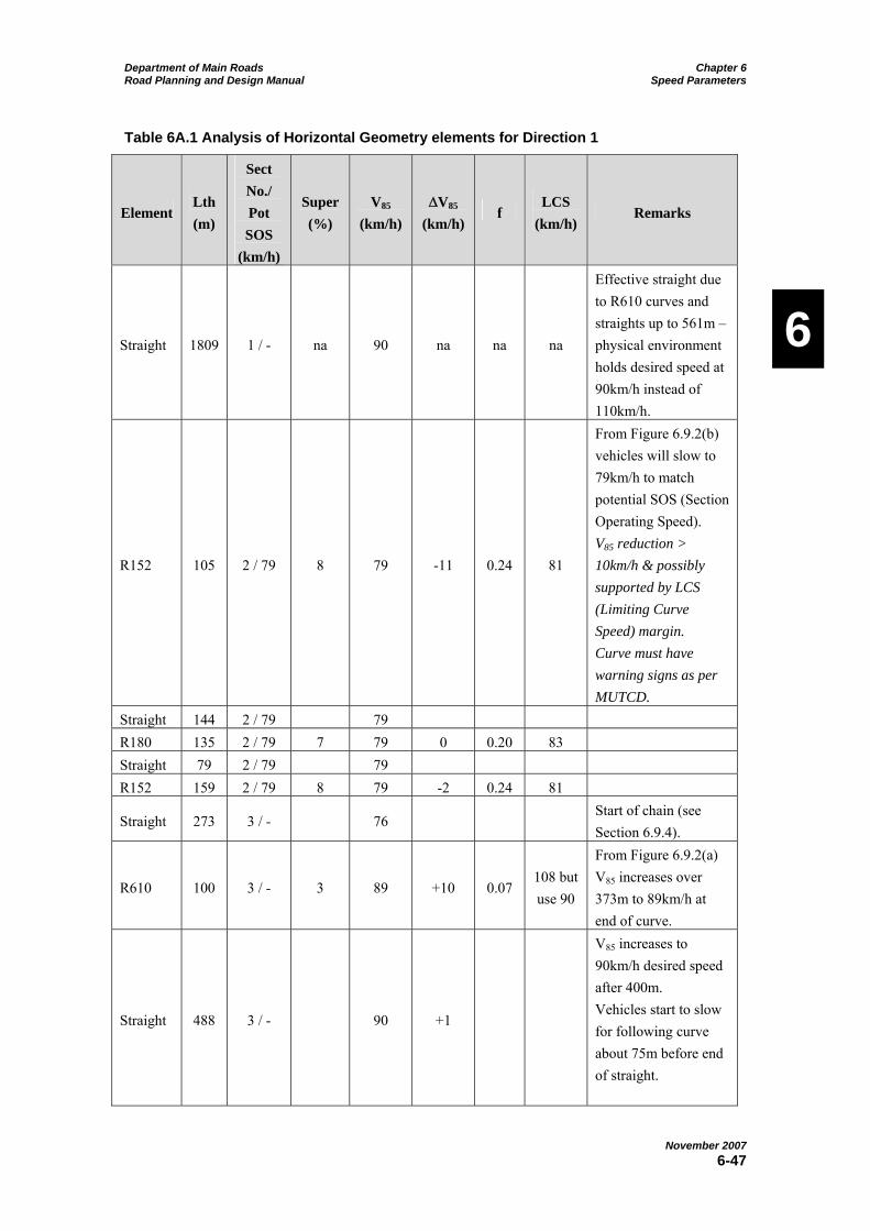
Department of Main Roads Chapter 6 Road Planning and Design Manual Speed Parameters
November 2007
6-47
6
Table 6A.1 Analysis of Horizontal Geometry elements for Direction 1
Element Lth
(m)
Sect
No./
Pot
SOS
(km/h)
Super
(%)
V85
(km/h)
V85
(km/h) f
LCS
(km/h) Remarks
Straight 1809 1 / - na 90 na na na
Effective straight due
to R610 curves and
straights up to 561m –
physical environment
holds desired speed at
90km/h instead of
110km/h.
R152 105 2 / 79 8 79 -11 0.24 81
From Figure 6.9.2(b)
vehicles will slow to
79km/h to match
potential SOS (Section
Operating Speed).
V85 reduction >
10km/h & possibly
supported by LCS
(Limiting Curve
Speed) margin.
Curve must have
warning signs as per
MUTCD.
Straight 144 2 / 79 79
R180 135 2 / 79 7 79 0 0.20 83
Straight 79 2 / 79 79
R152 159 2 / 79 8 79 -2 0.24 81
Straight 273 3 / - 76 Start of chain (see
Section 6.9.4).
R610 100 3 / - 3 89 +10 0.07 108 but
use 90
From Figure 6.9.2(a)
V85 increases over
373m to 89km/h at
end of curve.
Straight 488 3 / - 90 +1
V85 increases to
90km/h desired speed
after 400m.
Vehicles start to slow
for following curve
about 75m before end
of straight.

Department of Main Roads Chapter 6 Road Planning and Design Manual Speed Parameters
November 2007
6-48
6
Element Lth
(m)
Sect
No./
Pot
SOS
(km/h)
Super
(%)
V85
(km/h)
V85
(km/h) f
LCS
(km/h) Remarks
R244 105 4 / 85 3 85 -5 0.20 86
From Figure 6.9.2(b)
vehicles will slow to
85km/h to match
potential SOS.
Straight 364 5 / - 90 +5
V85 increases to
90km/h desired speed
after 200m.
R305 87
6 / 91
6 / 90
(SOS
capped
at
desired
speed)
3 90 0 0.18 92
Straight 190 6 / 90 90
R112 88 7 / 66 8
75
(use 75
since
only
slightly
> LCS)
-15
(-17 if
slow to
LCS)
0.32
(0.29
if
slow
to
LCS)
73
From Figure 6.9.2(b)
vehicles will slow to
75km/h but should
slow to 73km/h LCS
(or less).
Curve must have
warning signs and
chevron alignment
markers as per
MUTCD if not
improved.
Start of 1.5km with
steeper grades, smaller
horizontal curves and
shorter straights
matched with obvious
change in terrain.
This change in
environment helps
drivers slow the
necessary 15 to
17km/h.
Straight 162 7 / 66 75 0

Department of Main Roads Chapter 6 Road Planning and Design Manual Speed Parameters
November 2007
6-49
6
Element Lth
(m)
Sect
No./
Pot
SOS
(km/h)
Super
(%)
V85
(km/h)
V85
(km/h) f
LCS
(km/h) Remarks
R92
Tr45 99 7 / 66 10 66 -7 0.27 69
From Figure 6.9.2(b)
vehicles will slow to
66km/h SOS.
Straight 0.8 8 / 52
R50
Tr45 134 8 / 52 10 53 -13 0.34 53
Vehicles have to start
slowing during
transitions & previous
R92.
Significant increase in
side friction demand.
No LCS margin. At
absolute limit of
geometric consistency.
Curve must have
warning signs as per
MUTCD.
Straight 3 8 / 52 52
R61
Tr45 157 8 / 52 10 52 -1 0.25 59
Straight 37 9 / 82
R213 79 9 / 82 3 52 0 0.07 84
No speed increase
over 37+79m. Grade
+6.7% helps reduce
acceleration. Sections
8, 9 & 10 essentially
one section
Straight 6 10 / 50
R50
Tr45 130 10 / 50 10 50 -2 0.29 53
Straight 0.1 11 / 57
R76
Tr45 149 11 / 57 10 57 +7 0.24 64
Assume speed
increase to SOS
because of -5.2%
grade (see Section
6.9.2).

Department of Main Roads Chapter 6 Road Planning and Design Manual Speed Parameters
November 2007
6-50
6
Element Lth
(m)
Sect
No./
Pot
SOS
(km/h)
Super
(%)
V85
(km/h)
V85
(km/h) f
LCS
(km/h) Remarks
Straight 36 12 / 86 58 +1
Start of chain (see
Section 6.9.4).
Grades, curve, terrain
& view of road ahead
do not encourage
return to desired speed
yet (supported by
speed study data).
R214 91 12 / 86 3 61 +3 0.11 84
Grade -6.0%
127m from previous
R76 to end of this
curve. Speed increase
interpolated from
increase to following
R305 curve (see
Section 6.9.4).
Straight 51 12 / 86 63 Speed increase
interpolated
R305 78 12 / 86 3 65 +3 0.08 92
256m from previous
R76 to end of this
curve.
Grade –8.9%
From Figure 6.9.2(a)
V85 increases over
256m to at least
65km/h at end of
curve
Straight 41 13 /105
13 /90 67 +2
SOS capped at desired
speed
R457 381 13 /90 3 78 +11 0.07 101
Grade –8.9%
422m from previous
R305 to end of this
curve.

Department of Main Roads Chapter 6 Road Planning and Design Manual Speed Parameters
November 2007
6-51
6
Element Lth
(m)
Sect
No./
Pot
SOS
(km/h)
Super
(%)
V85
(km/h)
V85
(km/h) f
LCS
(km/h) Remarks
Straight 379 14 / - 89 +11
Terrain changing.
Drivers see return to
desired speed possible
and Figure 6.9.2(a)
shows V85 increases
over 379m to 89km/h
at end of straight.
305
Tr61 231 14 / 91 7 90 +1 0.14 97
Superelevation suits
opposite direction
Straight 1348 15 /110
110 (by
end of
straight)
+20
Further change in
terrain (flat)
encourages increase in
desired speed to
110km/h.
Design Issues with Direction 1
The 11km/h decrease in design speed for the first (R152) curve is slightly greater than the desirable maximum decrease between elements of 10km/h (see Section 6.7 and Table 6.7.2). The curve should have a margin with the Limiting Curve Speed being greater than the predicted operating speed. In this case, the 2km/h margin is limited. Nevertheless, any decrease in 85th percentile operating speed greater than 10km/h requires signing in accordance with Section 3.4 of the MUTCD. Given the mitigating signing treatment, the curve is acceptable if it is not feasible to increase the radius slightly. However, since this example involves overlay and widening, the design should be checked to see if the curve could be reconstructed with a slightly larger radius. Even though, Table 6.9.2 shows that increasing the radius to as much as 240m is
still going to result in a curve operating speed of 79km/h and a speed reduction of 11km/h, the increase in Limiting Curve Speed will provide a greater margin for driver error due to overdriving. For example, increasing the radius to 180m, 7% superelevation and 60m transition will require a 7km/h decrease in operating speed instead of a 9km/h decrease. Such a change would involve an increase in the curve secant of about 2.5m in this example, would reasonably limit the amount of existing pavement that was wasted, and provide a safety benefit.
Figure 6.9.2(b) shows that drivers will normally reduce speed from 90km/h to 75km/h for the seventh (R112) curve. However, this is still slightly greater than the limiting curve speed of 73km/h. Signage and chevron alignment markers in accordance with the MUTCD will be essential in order to help bring the operating

Department of Main Roads Chapter 6 Road Planning and Design Manual Speed Parameters
November 2007
6-52
6
speed to the limiting curve speed or less. Nevertheless, it is likely that the curve will be overdriven at 75km/h. Furthermore, the 15 to 17km/h decrease in operating speed adds to the issue of geometric inconsistency. The R112 curve is at best a borderline case and reasons for its retention will have to be documented as part of any defence for possible future liability. The documentation must include an investigation of the possibility of reconstructing the curve with a radius in the order of 125m with 7% superelevation and 60m transition. This would involve an increase in the curve secant of about 2.3m in this example. Any larger radius would result in too high a speed for the following R50 curves which are at the limit of acceptable operation.
The 13km/h decrease in design speed for the ninth (R50) curve is just above the desirable limit. There is no additional margin provided by the Limiting Curve Speed. However, the low operating speeds are likely to help the situation. Nevertheless, the curve is borderline in terms of geometric consistency. It will require a documented investigation into the
possibility of replacing the curve with a larger radius and, if not increased, signage in accordance with the MUTCD.
The side friction demand on both the R50 curves is close to the absolute maximum for the curve design speeds. Hence, the curve design speed in each case is almost equal to the Limiting Curve Speed. This is a case where little can be done without realignment because each curve has a common tangent point with the curve each side of it. Most other curves have a side friction demand between the desirable maximum and absolute maximum for the respective curve design speeds. This at least provides consistency in this example. Truck speeds on the R50 curves would need to be about 47km/h in order to keep the side friction demand at about 0.25. This speed difference with respect to cars is acceptable and realistic.
Note that the speed analysis in the opposite direction needs to be considered before any decisions on sections of realignment are finalised.
Table 6A.2 Analysis of Horizontal Geometry elements for Direction 2
Element Lth
(m)
Sect
No./
Pot
SOS
(km/h)
Super
(%)
V85
(km/
h)
V85
(km/h) f
LCS
(km/h) Remarks
Straight 1348 1 / - na 110 na na na
Effective straight due
to R610 to R1220
curves and straights
up to 353m –desired
speed = 110km/h

Department of Main Roads Chapter 6 Road Planning and Design Manual Speed Parameters
November 2007
6-53
6
Element Lth
(m)
Sect
No./
Pot
SOS
(km/h)
Super
(%)
V85
(km/
h)
V85
(km/h) f
LCS
(km/h) Remarks
R305
Tr61 231 2 / 91 7
100
97
-10
(-13 if
slow to
LCS)
0.19
(0.17
if slow
to
LCS)
97
From Figure 6.9.2(b)
vehicles will slow to
100km/h but should
slow to 97km/h LCS
(or less).
Physical environment
and road appearance
starts to change prior
to curve. Likely to
help drivers see need
to slow down to LCS
(or less) if aided by
signing.
Curve must have
warning signs and
chevron alignment
markers as per
MUTCD if not
improved.
Straight 379 3 / - 100 +3
Physical environment
and road appearance
changes further.
Assume desired speed
reduced to 100km/h.
R457 381 4 / 104 3 100 08 0.14 102
+8.9% grade,
therefore appropriate
to start using design
speed of a given curve
as desired speed for
the approach to the
following curve.
Straight 41 5 / 86
R305 78 5 / 86 3 92 -8 0.14 93
Grade +8.9%.
Now reasonable to
assume desired speed
now reduced to
92km/h.

Department of Main Roads Chapter 6 Road Planning and Design Manual Speed Parameters
November 2007
6-54
6
Element Lth
(m)
Sect
No./
Pot
SOS
(km/h)
Super
(%)
V85
(km/
h)
V85
(km/h) f
LCS
(km/h) Remarks
Straight 51 5 / 86
R214 91 5 / 86 3
6
86
(with
in-
crease
in
super
to 6%)
-6 0.21
84
(86
with
super
change
to 6%)
Grade +6.0% - aids
slowing for curve.
Increasing super to
6% increases LCS to
86km/h to match
speed that Figure
6.9.2(b) shows drivers
prepared to slow to.
Now reasonable to
assume desired speed
now reduced to
90km/h. even though
V85 is 86km/h.
Straight 36 6 / 57
R76
Tr45 149 6 / 57 10
68
64
-18
(-22 if
slow to
LCS)
0.38
(0.32
if slow
to
LCS)
64
From Figure 6.9.2(b)
vehicles will slow to
68km/h but have to
slow to 64km/h LCS
(or less). Major issue
with geometric
inconsistency. Curve
must have warning
signage as per
MUTCD if not
improved.
Straight 0.1 7 / 50
R50
Tr45 130 7 / 50 10 50
--18 to
-14 0.30 53
+5.2% grade aids
slowing for curve.
Curve must have
warning signs as per
MUTCD.
Straight 6 8 / 82 Start of chain (see
Section 6.9.4).
R213 79 8 / 82 3 51 +1 0.07 84
85m from previous
R50 to end of this
curve. Interpolated
speed increase.
Grade -6.7%.

Department of Main Roads Chapter 6 Road Planning and Design Manual Speed Parameters
November 2007
6-55
6
Element Lth
(m)
Sect
No./
Pot
SOS
(km/h)
Super
(%)
V85
(km/
h)
V85
(km/h) f
LCS
(km/h) Remarks
Straight 37 9 / 52 51
R61
Tr45 157 9 / 52 10 52 +2 0.25 59
V85 increases to SOS
within this curve
Straight 3 9 / 52
R50
Tr45 134 9 / 52 10 52 0 0.33 53
Near LCS but no
slowing required. In
sag VC which aids
visibility of curvature.
Straight 0.8 10 / 66 52 Start of chain (see
Section 6.9.4).
R92
Tr45 99 10 / 66 10 52 0 0.13 69
Common tangent
point with previous
curve. End of curve
94m from previous
curve. Crest VC. No
speed increase and V85
< 60km/h for
direction.
Straight 162 10 / 66 62 +10
-7.4% grade
Interpolated V85
between previous R92
and following R112
R112 88 10 / 66 8 66 +4 0.23 73
End of curve 250m
from end of previous
R92 curve.
Speed increase to
match 66km/h
potential SOS possible
due to low start speed
and grade (see Section
6.9.2)
End of curve at end of
1.5km constrained
section. Drivers see
return to 90km/h
desired speed possible
after this curve.

Department of Main Roads Chapter 6 Road Planning and Design Manual Speed Parameters
November 2007
6-56
6
Element Lth
(m)
Sect
No./
Pot
SOS
(km/h)
Super
(%)
V85
(km/
h)
V85
(km/h) f
LCS
(km/h) Remarks
Straight 190 11 / 91 72 +6
Start of chain (see
Section 6.9.4).
Interpolated V85
between previous
R112 and following
R305
R305 87 11 / 91 3 74 +2 0.11 92
End of curve 277m
from end of previous
R112 curve. V85
increase to 74km/h
and less than potential
SOS.
Straight 364 12 / - 85 +11
R244 105 13 / 85 3 85 0 0.20 86
Straight 488 14 / - 90 +5
90km/h reached after
200m of straight. V85
would increase further
if desired speed was
greater.
Have to confirm that
change in perception
of the road will not
lead to increase in
desired speed. In this
case, the 80km/h
speed limit at this
point confirms 90km/h
desired speed.
R610 100 14 / - 3 90 0 0.07 Use 90
Straight 273 14 / - 90 0 0

Department of Main Roads Chapter 6 Road Planning and Design Manual Speed Parameters
November 2007
6-57
6
Element Lth
(m)
Sect
No./
Pot
SOS
(km/h)
Super
(%)
V85
(km/
h)
V85
(km/h) f
LCS
(km/h) Remarks
R152 159 15 / 79 8 79 -11 0.24 81
From Figure 6.9.2(b)
vehicles will slow to
79 km/h to match
potential SOS.
V85 reduction >
10km/h & possibly
supported by LCS
margin.
Curve must have
warning signs as per
MUTCD.
Straight 79 15 / 79 79 0 V85 = SOS
R180 135 15 / 79 7 79 0 0.20 83 V85 = SOS
Straight 144 15 / 79 79 0
R152 105 15 / 79 8 79 0 0.24 81
Straight 331 16 / - 88
Design Problems with Direction 2
Figure 6A.3 shows that drivers will normally reduce speed from 110km/h to 100km/h for the first (R305) curve. However, this is still slightly greater than the limiting curve speed of 97km/h. Signing and chevron alignment markers in accordance with the MUTCD will be essential in order to help bring the operating speed to the limiting curve speed or less. Nevertheless, it is likely that the curve will be overdriven at 100km/h. Furthermore, the 10 to 13km/h decrease in operating speed adds to the issue of geometric inconsistency. This means that the R305 curve is at best a borderline case and reasons for its retention will have to be documented as part of any defence for possible future liability. The documentation must include an investigation of the possibility of
reconstructing the curve with a radius in the order of 440m with 6% superelevation and 80m transition.
With the fourth (R214) curve, drivers are only prepared to slow to the 86km/h Section Operating Speed. This is slightly greater than the limiting curve speed of 84km/h if the existing 3% superelevation is retained. Increasing the superelevation to 6% raises the limiting curve speed to 86km/h to match the predicted operating speed. This can be achieved by an increase in pavement depth, which reaches 0.27m on the outer edge of the curve (for 3.5m lanes and 1.0m shoulders). However, the R214 curve has to be further investigated in relation to the following R76 curve.
The fifth (R76) curve has a major problem with geometric inconsistency. Firstly, the predicted operating speed of 68km/h exceeds the Limiting Curve Speed of
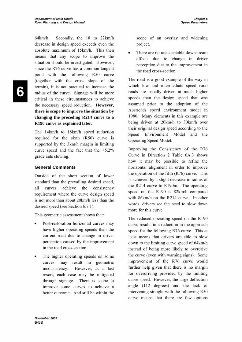
Department of Main Roads Chapter 6 Road Planning and Design Manual Speed Parameters
November 2007
6-58
6
64km/h. Secondly, the 18 to 22km/h decrease in design speed exceeds even the absolute maximum of 15km/h. This then means that any scope to improve the situation should be investigated. However, since the R76 curve has a common tangent point with the following R50 curve (together with the cross slope of the terrain), it is not practical to increase the radius of the curve. Signage will be more critical in these circumstances to achieve the necessary speed reduction. However, there is scope to improve the situation by changing the preceding R214 curve to a R190 curve as explained later.
The 14km/h to 18km/h speed reduction required for the sixth (R50) curve is supported by the 3km/h margin in limiting curve speed and the fact that the +5.2% grade aids slowing.
General Comments
Outside of the short section of lower standard than the prevailing desired speed, all curves achieve the consistency requirement where the curve design speed is not more than about 20km/h less than the desired speed (see Section 6.7.1).
This geometric assessment shows that:
Post-restoration horizontal curves may have higher operating speeds than the current road due to change in driver perception caused by the improvement in the road cross-section.
The higher operating speeds on some curves may result in geometric inconsistency. However, as a last resort, each case may be mitigated through signage. There is scope to improve some curves to achieve a better outcome. And still be within the
scope of an overlay and widening project.
There are no unacceptable downstream effects due to change in driver perception due to the improvement in the road cross-section.
The road is a good example of the way in which low and intermediate speed rural roads are usually driven at much higher speeds than the design speed that was assumed prior to the adoption of the Austroads speed environment model in 1980. Many elements in this example are being driven at 20km/h to 30km/h over their original design speed according to the Speed Environment Model and the Operating Speed Model.
Improving the Consistency of the R76 Curve in Direction 2 Table 6A.3 shows how it may be possible to refine the horizontal alignment in order to improve the operation of the fifth (R76) curve. This is achieved by a slight decrease in radius of the R214 curve to R190m. The operating speed on the R190 is 82km/h compared with 86km/h on the R214 curve. In other words, drivers see the need to slow down more for this curve.
The reduced operating speed on the R190 curve results in a reduction in the approach speed for the following R76 curve. This at least means that drivers are able to slow down to the limiting curve speed of 64km/h instead of being more likely to overdrive the curve (even with warning signs). Some improvement of the R76 curve would further help given that there is no margin for overdriving provided by the limiting curve speed. However, the large deflection angle (112 degrees) and the lack of intervening straight with the following R50 curve means that there are few options

Department of Main Roads Chapter 6 Road Planning and Design Manual Speed Parameters
November 2007
6-59
6
available to change the R76 curve within the scope of a restoration project.
The 10km/h speed reduction for the new R190 curve (instead of the 6km/h reduction for the R214 curve) is supported by having some margin for overdriving with the limiting curve speed (there was none with the R214 curve).
The new R190 curve has a change in the curve secant of 0.54m. This should be in the scope of a road restoration project, given the improvement in geometric consistency.
Table 6A.3 Assessment of Possible Refinement of Horizontal Geometry to Improve
Geometric Consistency of Direction 2
Element Lth
(m)
Sect
No./
Pot
SOS
(km/h)
Super
(%)
V85
(km/
h)
V85
(km/h) f
LCS
(km/h) Remarks
Straight 41 5 / 86
R305 78 5 / 86 3 92 -8 0.14 93
Grade +8.9%.
Now reasonable to
assume desired speed
now reduced to
92km/h.
Straight 56 5A / 86
R190 81 5A / 77 8 82 -10 0.20 85
Grade +6.0% - aids
slowing for curve.
Figure 6.9.2(b) shows
drivers prepared to
slow to 82km/h.
3km/h margin
provided by LCS.
Now reasonable to
assume desired speed
now reduced to
90km/h. even though
V85 is 82km/h.
Straight 41 6 / 57

Department of Main Roads Chapter 6 Road Planning and Design Manual Speed Parameters
November 2007
6-60
6
Element Lth
(m)
Sect
No./
Pot
SOS
(km/h)
Super
(%)
V85
(km/
h)
V85
(km/h) f
LCS
(km/h) Remarks
R76
Tr45 149 6 / 57 10 64 -18 0.32 64
Figure 6.9.2(b)
vehicles will slow to
64km/h but have no
LCS margin.
Still issue with
geometric
inconsistency due to
18km/h speed
reduction. But +5.2%
grade aids slowing for
curve. Curve must
have warning signs
and chevron
alignment markers as
per MUTCD if not
improved.

Department of Main Roads Chapter 6 Road Planning and Design Manual Speed Parameters
November 2007
6-61
6
Appendix 6B: Operating Speeds on Long Grades Steeper than 5%
Figure 6B.1 shows the horizontal alignment of road on a long steep grade. The vertical alignment has a constant 10% grade (Figure 6B.3). The horizontal alignment consists of quite generous radii curves which results in operating speeds on the steep downgrade of about 105km/h (See Table 6.9.2).
Eighty-fifth percentile heavy vehicles speeds on the downgrade will be likely to be around 20km/h. This creates a potential relative speed of 85km/h between the faster lighter vehicles and the slower heavy vehicles creating a potentially high rear-end vehicle accident rate particularly if this
roadway has a high percentage of heavy vehicles. This is compounded if inadequate visibility around curves is provided and this is common on steep downgrades due to the large cuts that are usually necessary.
Figure 6B.2 shows a slower speed horizontal alignment for the same vertical alignment. Operating speeds of about 70km/h occur with this layout. The potential relative speed between the lighter and heavier vehicles in this case is 50km/h. This is a reduction of 35km/h over the layout given in the upper diagram and will significantly reduce the rear-end vehicle accident rate. The cost of constructing this lower speed alignment is also usually considerably less.
500
450
500
700
Figure 6B.1 Horizontal Alignment – Operating Speed 105km/h
R130
R125
R100
R90 R125 R150
Figure 6B.2 Horizontal Alignment – Operating Speed 70km/h
10%
Figure 6B.3 Vertical Alignment

Department of Main Roads Chapter 6 Road Planning and Design Manual Speed Parameters
November 2007
6-62
6
Appendix 6C: Symbols used in this Chapter
Symbol Explanation
f Side Friction Factor
L Length of vehicle path on the particular horizontal geometric element (m)
LCS Limiting Curve Speed
R Radius of vehicle path on the particular horizontal geometric element (m)
Sr 85th percentile potential relative speed (km/h)
SOS Section Operating Speed
Tr Transition
V85 85th percentile speed on the particular horizontal geometric element (km/h)
V85 Decrease in 85th percentile speed at the start of the particular horizontal geometric
element (km/h)
VC Vertical Curve
VDesign Design Speed (km/h)
VDesired Desired Speed (km/h)
VOperating Operating Speed (km/h)
VTarget Target Speed (km/h)