roadway supporting technology applied to three …
TRANSCRIPT
Zhang, S., et al.: Roadway Supporting Technology Applied to Three Soft ... THERMAL SCIENCE: Year 2019, Vol. 23, Suppl. 3, pp. S887-S895 S887
ROADWAY SUPPORTING TECHNOLOGY APPLIED TO THREE SOFT COAL SEAM AT YANLONG MINING AREA IN CHINA
by
Sheng ZHANG a,b, Jie LI a, and Jianhong MA a,b*
a School of Energy Science and Engineering, Henan Polytechnic University, Henan, China b Collaborative Innovation Center of Coal Work Safety, Henan, China
Original scientific paper https://doi.org/10.2298/TSCI180322124Z
The compressive strength of coal in Yanlong mine area of China is less than 3 MPa. Basically, it is powdery. The roof and floor rocks are mudstone. Therefore, this coal seam is a typical “three soft” coal seam. Anchor and cable cannot be used due to low anchoring force. This paper describes how to support this type of soft coal roadway. The deformation characteristics of soft coal roadway were investigated. Results show the conventional U-shaped steel support is not subjected to uniform load, which bearing capacity can be improved by structural compensation, such as addition of horizontal and vertical beams made of U-shaped steel. In addition, by drilling pressure-relief holes in the ribs of a soft coal roadway, the stress distri-bution of surround rock in the roadway can be improved, which can transfer the high stress in the surrounding rock to deeper parts and reduce the pressure on the artificial support. A support method is to combine the strengthened U-shaped steel support with pressure-relieving drill holes, providing an economic and efficient way to support the very soft coal roadways.Key words: soft coal seam, pressure-relieving drilling holes, high stress,
coal roadway, u-shaped steel support
Introduction
As an important material base of national economy, it is no exaggeration say that fossil energy is the lifeline for rapid development of the country [1]. In the composition of fossil fuels, compared with other countries, China’s demand for coal is stronger. There are three soft coal seams in some mines in China, within which the strength of coal rock is lower than average. In these coal seams, the stability of roadway surrounding rock will become very difficult, when it encounters high stress, and at the same time, is subjected to blast or the dynamic disturbance caused by roof failure [2]. The so-called three soft coal seam refers to soft roof, soft coal and soft bottom of the coal seam. At present, there is no unified definition of three soft coal seams. It is generally considered that the uniaxial compressive strength of rock in the roof and floor is less than 15 MPa and the one of coal is less than 6 MPa. In such conditions, failure of the orig-inal support from start to appear successively at many mines, the surrounding rocks of roadway show obvious characteristics of soft rocks such as large deformation and long duration [3-5].
Based on the original concept of supporting, that the surrounding rock of three soft coal seam is soft and broken, and the anchor and cable supporting ability is low, people now use a U-shaped-steel + bolt-mesh-anchor combined supporting method [6-11]. At the same time,
* Corresponding author, e-mail: [email protected]
Zhang, S., et al.: Roadway Supporting Technology Applied to Three Soft ... S888 THERMAL SCIENCE: Year 2019, Vol. 23, Suppl. 3, pp. S887-S895
according to surrounding rock loose ring support theory, people propose a supporting form of bolt-beam-net + anchor cable [12, 13]. But these two methods are still only valid for the three soft coal seams with enough coal strength. Besides, for the crushed three soft coal seam, based on the idea that strong top to help the sides, and strong sides to help the top, the powerful com-posite support scheme was proposed, which conclude U-shape tent, anchor rod, anchor cable, steel belt, grouting and I-beam single steel support (wearing shoes) [14-17]. In conclusion, the existing researches, on the supporting methods of the three soft coal seams, still give priority to the anchor net supporting technology. However, if the coal seam is thick and the coal is powdery, their strength shall be so low that the anchor and cable will lose bolting ability. At this time, we must study more new supporting methods so as to adapt to such conditions.
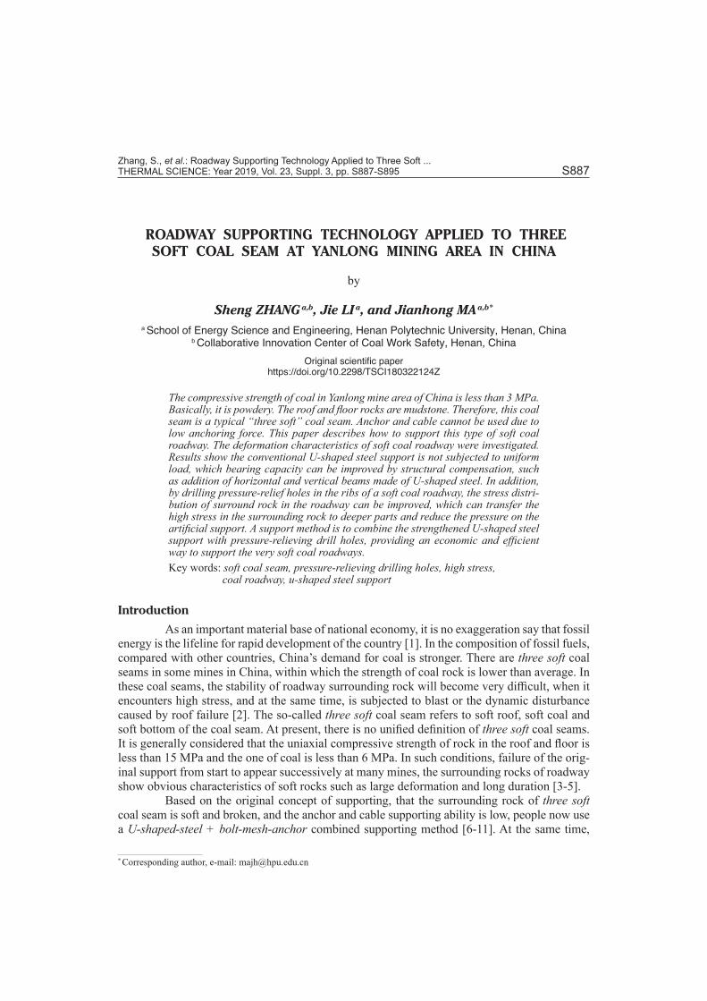
Dragon mining area in China is located in the geologically complicated tectonic zone of Songshan Mountain, having 72 mountain ridges. Therefore, coal seams in this area are extremely non-uniform and very weak with well-developed fractures, which is the typical characteristic of tectonic coal. Figure 1 shows the topographic map of Yonghua No. 1 mine in Dragon mining area.
The major coal seam 21 mined in the Dragon mining dips 9° ~ 20°. It is so soft, less than 3 MPa in compressive strength, that it can be crushed easily by hand. The immediate roofs
are carbonaceous mudstone and shale, and the main roof is siltstone. The floor rock is carbona-ceous mudstone having abundant plant fossils. Therefore, this coal seam is a typical three soft coal seam.
Sun [18] studied the reliability theory of mine supporting systems and found that roof bolting has only limited applicability. In the worst case, the bolt will be pulled out, when the pre-tension is applied. Therefore, the bolting method cannot be used. Xie et al. [19] analyzed the structural stability of U-shaped steel support and its control technology. When the yielding steel support made of U36 steel was installed in the mine, it did not achieve the ideal supporting per-formance. Field observations showed that the largest cross-sectional deformation of coal road-way could exceed 30% about one half month after development. Usually, 70 ~ 90% of the coal roadways require repairs, and most of the roadways need repeated repairs and re-supports, which slowed down roadway development, and increases supporting cost and potential safety hazards.
As for various types of steel supports in Chinese coal mines, the U36-shaped steelsup-port is a conventional support having the highest bearing capacity. But it is not strong enough for soft coal roadways. This paper provides guidelines for enhancing the supporting capacity of the whole U36-shaped steelsupport through structural compensation and optimization. At the same time, a method of drilling holes for pressure-relief is adopted so that the high stresses in the surrounding rocks can be transferred to farther away. The combination of these two methods provides a way to ensure the stability of the soft coal roadways.
Stress analysis of U-shaped steel support
The ANSYS software was used to model the conventional U36-shaped steelsupport in soft coal roadways. The model with boundary condition is shown in fig. 2, which is 75 m wide by 75 m high with the roadway at the center. The vertical displacement on the lower
Yonghua No. 1 mine inDragon mining area
Figure 1. Topographic map of Yonghua No. 1 mine in Dragon mining area, China
Zhang, S., et al.: Roadway Supporting Technology Applied to Three Soft ... THERMAL SCIENCE: Year 2019, Vol. 23, Suppl. 3, pp. S887-S895 S889
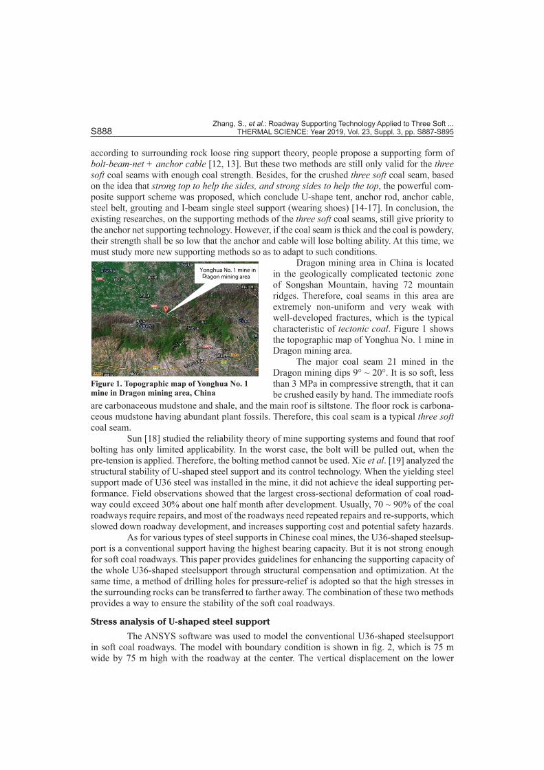
boundary was fixed, while the horizontal and the top boundary were free. The vertical stress was applied on the top boundary, and the horizontal stress was applied on the left-side and right-side boundaries. The Mohr-Coulomb yield criterion was used. The model of U-shaped steel support consisted of two nodes beam element, and the overlap parts of the steel support were simulat-ed with equivalent material processing method, i. e., the lap part and clamps of the support were replaced by the equivalent cross-section bar. The vertical stress σx, horizontal stress σy, and lateral pressure coefficient were 8.38 MPa, 12.56 MPa, and 1.5 MPa, respectively. Mechanical parame-ters of surrounding rock were shown as tab. 1. Six layers were considered.
Table 1. Mechanical parameters of surrounding rockNo of layer Lithology Thickness
[m] E [GPa] μ C [MPa] φ [°] γ [kN·m–3] Position
1 Medium sandstone 6.0 41.5 0.22 3.2 31 26.2 Hard roof
2 Sandy mudstone 3.5 29.3 0.20 2.9 29 24.6 Immediate roof
3 Mudstone 0.5 16.7 0.32 2.1 27 24.1 False roof
4 Coal 5.9 6.0 0.30 0.4 20 13.0 Coal
5 Sandy mudstone 3.0 29.3 0.20 2.9 29 24.6 Immediate floor
6 Medium sandstone 9.0 41.5 0.22 3.2 31 26.2 Hard floor
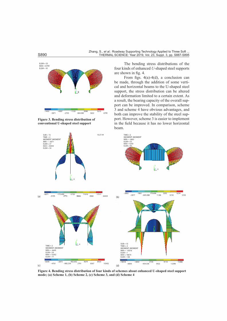
Figure 3 shows the bending stress distribution of the U-shaped steel support. The bending stresses of the top and side parts are larger. These parts deform easily due to lack of constraint. Table 2 shows the four kinds of schemes about enhanced U-shaped steel support mode.
Table 2. Four kinds of schemes about enhanced U-shaped steel support modeScheme number Support description Schematic diagram
1 U-shaped steel support with a vertical beam
2 U-shaped steel support with a horizontal beam
3 U-shaped steel support with a horizontal beam and two vertical beams
4 U-shaped steel support with two horizontal beams and two vertical beams
σx
Sandy
Siltston
Charcoal
mudstone
Coal
Charcoal mudstone
Mudstone
Roadway
Steel support
Siltston
σx
σy
Figure 2. Model with boundary condition
Zhang, S., et al.: Roadway Supporting Technology Applied to Three Soft ... S890 THERMAL SCIENCE: Year 2019, Vol. 23, Suppl. 3, pp. S887-S895
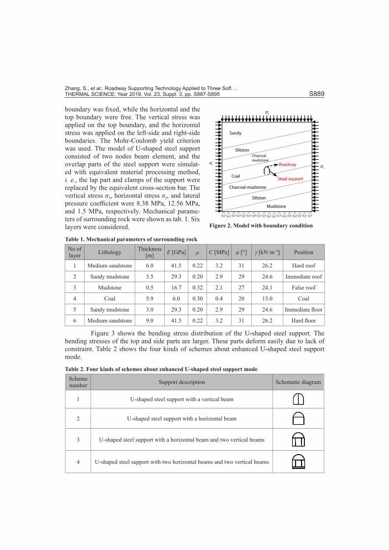
The bending stress distributions of the four kinds of enhanced U-shaped steel supports are shown in fig. 4.
From figs. 4(a)-4(d), a conclusion can be made, through the addition of some verti-cal and horizontal beams to the U-shaped steel support, the stress distribution can be altered and deformation limited to a certain extent. As a result, the bearing capacity of the overall sup-port can be improved. In comparison, scheme 3 and scheme 4 have obvious advantages, and both can improve the stability of the steel sup-port. However, scheme 3 is easier to implement in the field because it has no lower horizontal beam.
SUB = 15TIME = 2IMOMENT JMOMENTMIN = –6071ELEM = 37MAX = 20459ELEM = 54
10.27.44
–6071 –175.499–3123 2772
–57208668
11616 175114564 20459
X
Y
Z
X
Y
Z
TIME = 2IMOMENT JMOMENTMIN = –3892ELEM = 55MAX = 5250ELEM = 93
–3892 –1861–2877
170.69611.86
2202 42343218 5250–845.088
TIME = 2IMOMENT JMOMENTMIN = –6649ELEM = 54MAX = 10342ELEM = 77
X
Y
Z
–6649 –2873–4761
902.6922791
4679 84546567 10342–985.254
SUB = 15TIME = 2IMOMENT JMOMENTMIN = –10018ELEM = 1MAX = 18674ELEM = 148
X
Y
Z
–10018 –3642–6830
27345922
9110 1548612298–454.336
(a) (b)
(c) (d)
Figure 4. Bending stress distribution of four kinds of schemes about enhanced U-shaped steel support mode; (a) Scheme 1, (b) Scheme 2, (c) Scheme 3, and (d) Scheme 4
ELEM = 55
MAX = 6799
ELEM = 91
–7455 –4287–5871 –2703
–1120464.048
2048 52153632 6799
XYZ
Figure 3. Bending stress distribution of conventional U-shaped steel support
Zhang, S., et al.: Roadway Supporting Technology Applied to Three Soft ... THERMAL SCIENCE: Year 2019, Vol. 23, Suppl. 3, pp. S887-S895 S891
Numerical and experimental analyses of pressure-relief drill holes
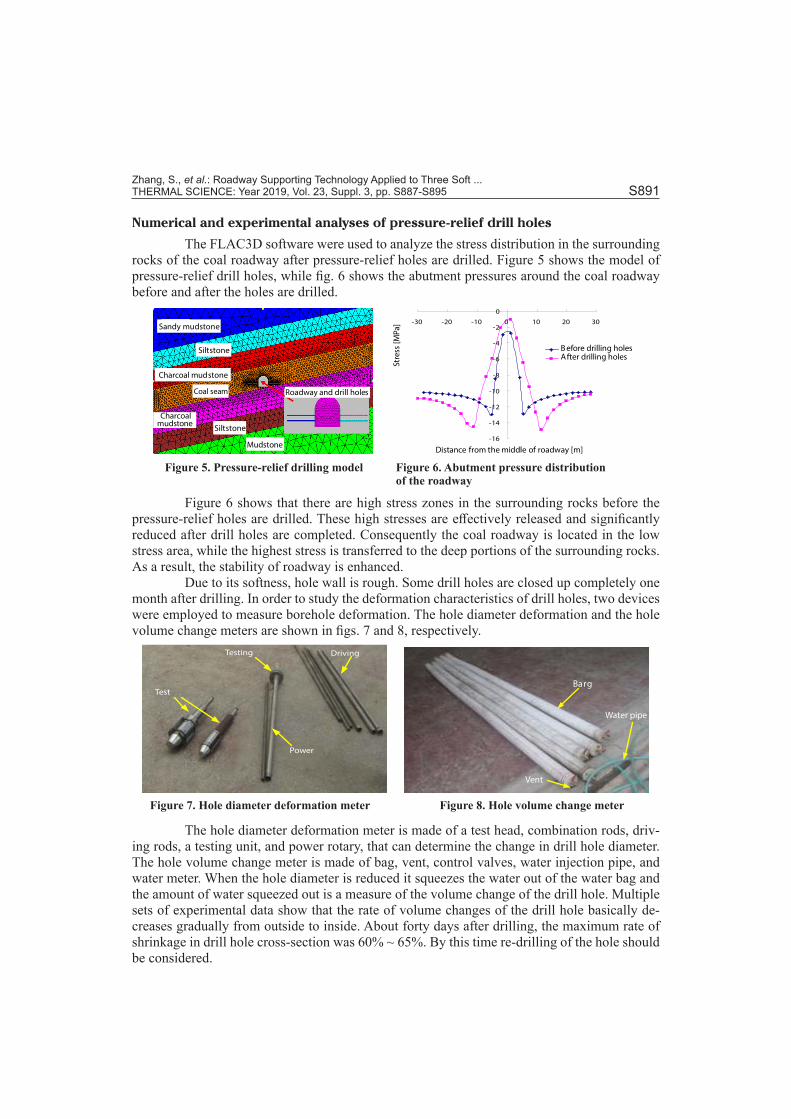
The FLAC3D software were used to analyze the stress distribution in the surrounding rocks of the coal roadway after pressure-relief holes are drilled. Figure 5 shows the model of pressure-relief drill holes, while fig. 6 shows the abutment pressures around the coal roadway before and after the holes are drilled.
Sandy mudstone
Siltstone
Charcoal mudstone
Coal seam
Charcoalmudstone
Siltstone
Mudstone
Roadway and drill holes
-16
-14
-12
-10
-8
-6
-4
-2
0
-30 -20 -10 0 10 20 30
���
���
Distance from the middle of roadway [m]
B efore drilling holesAfter drilling holes
Str
ess
[MP
a]
Figure 6 shows that there are high stress zones in the surrounding rocks before the pressure-relief holes are drilled. These high stresses are effectively released and significantly reduced after drill holes are completed. Consequently the coal roadway is located in the low stress area, while the highest stress is transferred to the deep portions of the surrounding rocks. As a result, the stability of roadway is enhanced.
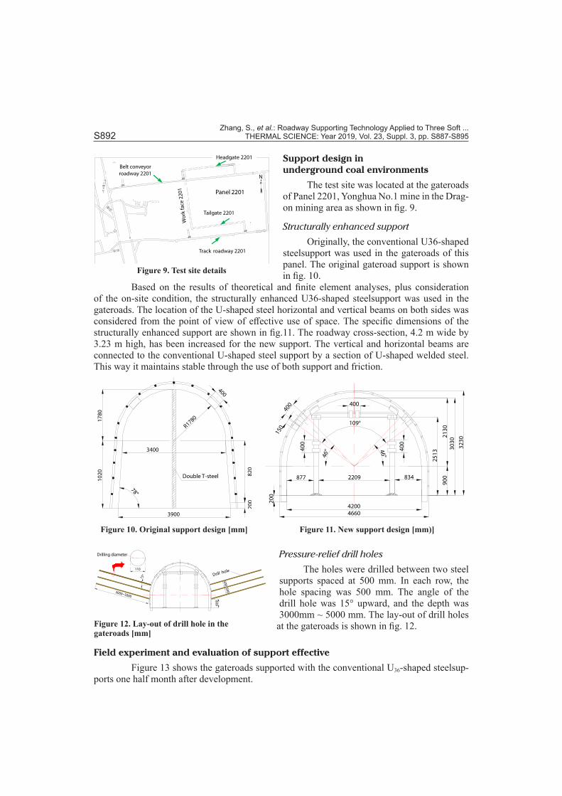
Due to its softness, hole wall is rough. Some drill holes are closed up completely one month after drilling. In order to study the deformation characteristics of drill holes, two devices were employed to measure borehole deformation. The hole diameter deformation and the hole volume change meters are shown in figs. 7 and 8, respectively.
Test
Driving
Power
Testing
Barg
Vent
Water pipe
Figure 7. Hole diameter deformation meter Figure 8. Hole volume change meter
The hole diameter deformation meter is made of a test head, combination rods, driv-ing rods, a testing unit, and power rotary, that can determine the change in drill hole diameter. The hole volume change meter is made of bag, vent, control valves, water injection pipe, and water meter. When the hole diameter is reduced it squeezes the water out of the water bag and the amount of water squeezed out is a measure of the volume change of the drill hole. Multiple sets of experimental data show that the rate of volume changes of the drill hole basically de-creases gradually from outside to inside. About forty days after drilling, the maximum rate of shrinkage in drill hole cross-section was 60% ~ 65%. By this time re-drilling of the hole should be considered.
Figure 5. Pressure-relief drilling model Figure 6. Abutment pressure distribution of the roadway
Zhang, S., et al.: Roadway Supporting Technology Applied to Three Soft ... S892 THERMAL SCIENCE: Year 2019, Vol. 23, Suppl. 3, pp. S887-S895
Support design in underground coal environments
The test site was located at the gateroads of Panel 2201, Yonghua No.1 mine in the Drag-on mining area as shown in fig. 9.
Structurally enhanced support
Originally, the conventional U36-shaped steelsupport was used in the gateroads of this panel. The original gateroad support is shown in fig. 10.
Based on the results of theoretical and finite element analyses, plus consideration of the on-site condition, the structurally enhanced U36-shaped steelsupport was used in the gateroads. The location of the U-shaped steel horizontal and vertical beams on both sides was considered from the point of view of effective use of space. The specific dimensions of the structurally enhanced support are shown in fig.11. The roadway cross-section, 4.2 m wide by 3.23 m high, has been increased for the new support. The vertical and horizontal beams are connected to the conventional U-shaped steel support by a section of U-shaped welded steel. This way it maintains stable through the use of both support and friction.
10
20
20
08
20
Double T-steel
R1780
400
17
80
3900
3400
78°
4004
00
40
0
400
109°
46
°46
°
20
0
42004660
2209877 834
25
13
90
02
13
0
30
30
32
30
150
Pressure-relief drill holes
The holes were drilled between two steel supports spaced at 500 mm. In each row, the hole spacing was 500 mm. The angle of the drill hole was 15° upward, and the depth was 3000mm ~ 5000 mm. The lay-out of drill holes
at the gateroads is shown in fig. 12.
Field experiment and evaluation of support effective
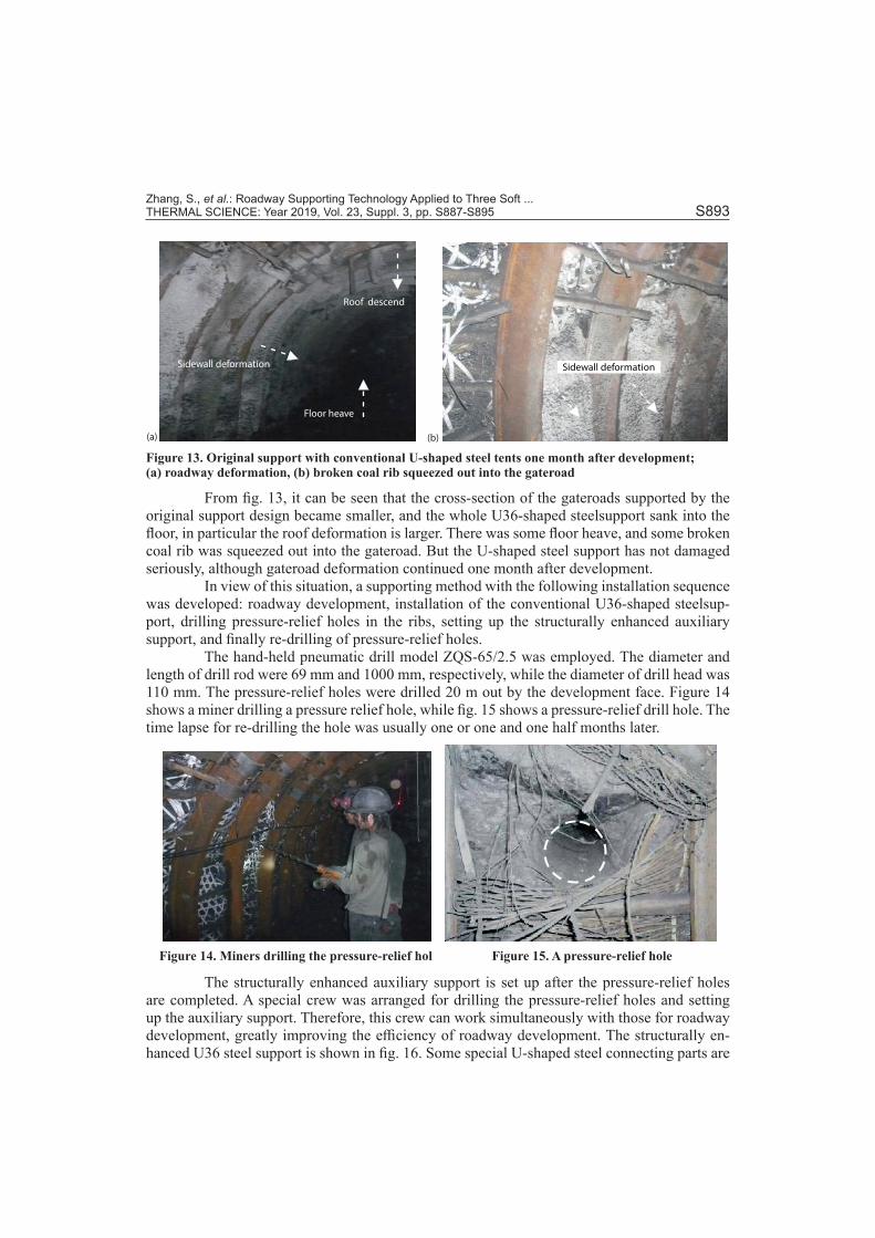
Figure 13 shows the gateroads supported with the conventional U36-shaped steelsup-ports one half month after development.
���� � 70����
������
2201�����
���
���
1#�
�0#��
2#�
�
2#�
�
#��
2201� ���
22
�
��
��
�
2201���
22
�
�
��
�
1
22
01�
��
2201���
2201
��
Track roadway 2201
Tailgate 2201
Headgate 2201
Belt conveyor
roadway 2201
Panel 2201
Wo
rkfa
ce2
20
1N
Figure 9. Test site details
Figure 10. Original support design [mm] Figure 11. New support design [mm)]
50
05
00
Drill hole
3000~5000
60
0
Drilling diameter
110
15°
Figure 12. Lay-out of drill hole in the gateroads [mm]
Zhang, S., et al.: Roadway Supporting Technology Applied to Three Soft ... THERMAL SCIENCE: Year 2019, Vol. 23, Suppl. 3, pp. S887-S895 S893
Roof descend
Floor heave
Sidewall deformation Sidewall deformation
(a) (b)
Figure 13. Original support with conventional U-shaped steel tents one month after development; (a) roadway deformation, (b) broken coal rib squeezed out into the gateroad
From fig. 13, it can be seen that the cross-section of the gateroads supported by the original support design became smaller, and the whole U36-shaped steelsupport sank into the floor, in particular the roof deformation is larger. There was some floor heave, and some broken coal rib was squeezed out into the gateroad. But the U-shaped steel support has not damaged seriously, although gateroad deformation continued one month after development.
In view of this situation, a supporting method with the following installation sequence was developed: roadway development, installation of the conventional U36-shaped steelsup-port, drilling pressure-relief holes in the ribs, setting up the structurally enhanced auxiliary support, and finally re-drilling of pressure-relief holes.
The hand-held pneumatic drill model ZQS-65/2.5 was employed. The diameter and length of drill rod were 69 mm and 1000 mm, respectively, while the diameter of drill head was 110 mm. The pressure-relief holes were drilled 20 m out by the development face. Figure 14 shows a miner drilling a pressure relief hole, while fig. 15 shows a pressure-relief drill hole. The time lapse for re-drilling the hole was usually one or one and one half months later.
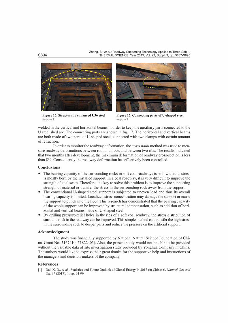
The structurally enhanced auxiliary support is set up after the pressure-relief holes are completed. A special crew was arranged for drilling the pressure-relief holes and setting up the auxiliary support. Therefore, this crew can work simultaneously with those for roadway development, greatly improving the efficiency of roadway development. The structurally en-hanced U36 steel support is shown in fig. 16. Some special U-shaped steel connecting parts are
Figure 14. Miners drilling the pressure-relief hol Figure 15. A pressure-relief hole
Zhang, S., et al.: Roadway Supporting Technology Applied to Three Soft ... S894 THERMAL SCIENCE: Year 2019, Vol. 23, Suppl. 3, pp. S887-S895
welded in the vertical and horizontal beams in order to keep the auxiliary parts connected to the U steel shed arc. The connecting parts are shown in fig. 17. The horizontal and vertical beams are both made of two parts of U-shaped steel, connected with two clamps with certain amount of retraction.
In order to monitor the roadway deformation, the cross point method was used to mea-sure roadway deformations between roof and floor, and between two ribs. The results indicated that two months after development, the maximum deformation of roadway cross-section is less than 8%. Consequently the roadway deformation has effectively been controlled.
Conclusions
y The bearing capacity of the surrounding rocks in soft coal roadways is so low that its stress is mostly born by the installed support. In a coal roadway, it is very difficult to improve the strength of coal seam. Therefore, the key to solve this problem is to improve the supporting strength of material or transfer the stress in the surrounding rock away from the support.
y The conventional U-shaped steel support is subjected to uneven load and thus its overall bearing capacity is limited. Localized stress concentration may damage the support or cause the support to punch into the floor. This research has demonstrated that the bearing capacity of the whole support can be improved by structural compensation, such as addition of hori-zontal and vertical beams made of U-shaped steel.
y By drilling pressure-relief holes in the ribs of a soft coal roadway, the stress distribution of surround rock in the roadway can be improved. This simple method can transfer the high stress in the surrounding rock to deeper parts and reduce the pressure on the artificial support.
Acknowledgment
The study was financially supported by National Natural Science Foundation of Chi-na(Grant No. 5167410, 51822403). Also, the present study would not be able to be provided without the valuable data of site investigation study provided by Yonghua Company in China. The authors would like to express their great thanks for the supportive help and instructions of the managers and decision-makers of the company.
References[1] Dai, X. D., et al., Statistics and Future Outlook of Global Energy in 2017 (in Chinese), Natural Gas and
Oil, 37 (2017), 1, pp. 94-99
Figure 16. Structurally enhanced U36 steel support
Figure 17. Connecting parts of U-shaped steel support
Zhang, S., et al.: Roadway Supporting Technology Applied to Three Soft ... THERMAL SCIENCE: Year 2019, Vol. 23, Suppl. 3, pp. S887-S895 S895
[2] Li, C. Y., et al., The Characteristics of Coal Mine Pressure and the Design and Practice of the Hydraulic Support for the Three Soft Coal Seam, China Coal, (1995), 6, pp. 28-32
[3] Shen, S. P., et al., Support Design and Practice for Large Section Roadway in Deep Three-Soft Coal Seam, Coal Engineering, 47 (2015),10, pp. 45-47
[4] Gao, M. Z., et al., Field Experiments on Fracture Evolution and Correlations between Connectivity and Abutment Pressure under Top Coal Caving Conditions, International Journal of Rock Mechanics and Mining Science, 111 (2018), Nov., pp. 84-93
[5] Li, Z. Z., et al., Research and Implementation Three Soft Coal Roadway Supporting Prestressed Steel Column, Coal Technology, 33 (2014), 7, pp. 147-149
[6] Zheng, Z. W., et al., Optimization on Supporting Parameters of Three Soft Coal Seam Roadway Sur-rounding Rock with High Stress in Deep Mine, Coal Technology, 36 (2017), 1, pp. 78-80
[7] Jiang, Y. J., et al., Study on Carrying Capacity of Bolt Support in Three-Soft Coal Seam Roadway Drifting along Goaf, Coal Technology, 35 (2016), 11, pp. 24-27
[8] Jiang, Y. J., et al., Research on Bolt Mash Supporting Technology for Three Soft Coal Seam Roadway in Zhaojiazhai Mine, Coal Technology, 35 (2016), 6, pp. 28-30
[9] Deng, P. H., et al., Study of Key Technologies of Support in Three Soft Coal Seam Roadway, Coal Tech-nology. 33 (2014), 4, pp. 118-121
[10] Bian, W. D., Discussion on Grouting Technology of Three Soft Coal Seam Wall, Shandong Industrial Technology, (2013), 12, pp. 95
[11] Huang, Z. B., Practice of Combined Support of Roadway Anchor and Pillar in Three Soft Coal Seam, Coal Science & Technology Magazine, (2011), 4, pp. 67-68
[12] Li, K. G., et al., Mining Gateway Support Technology Under Multiple Mining Activities in Seam with Soft Roof, Soft Coal and Soft Floor, Coal Science and Technology. 38 (2010), 9, pp. 4-9
[13] Liu, Z. C., et al., Roadway Supporting Technology in Deep Three-Soft Coal Seam in Baiji Coal Mine, Safety in Coal Mines, 61 (2008), 12, pp. 61-62
[14] Wang, X. F., et al., Enhanced Support Technology for Key Area of the Roadway in Large Inclined Angle Three-Soft Coal Seam. Journal of Mining and Safety Engineering, 34 (2017), 2, pp. 208-213
[15] Shi, J. H., Study on the Support Technology of Roadway Effected by Sliding Geological Structure in Three-Soft Coa1 Seam of Gaocheng Coal Mine, China University of Mining and Technology, 2014
[16] Zhang, C. G, et al., Three Soft Coal Roadway Strong Composite Supporting Technology, China Energy and Environmental Protection, (2012), 2, pp. 14-1
[17] Fan, G. J., et al., Compound Support in the Coal Mine Soft Research and Application of Coal Seam, Journal of North China Institute of Science and Technology. 8 (2011), 1, pp. 37-40
[18] Sun, G. Y., Research on Reliability Theory of Mine Support System, Liaoning Technical University, 2003[19] Xie, W. B., et al., Structural Stability of U-Steel Support and Its Control Technology, Chinese Journal of
Rock Mechanics and Engineering, 29 (2010), S2, pp. S3743-S3748
Paper submitted: March 22, 2018Paper revised: June 19, 2018 Paper accepted: December 11, 2018
© 2019 Society of Thermal Engineers of SerbiaPublished by the Vinča Institute of Nuclear Sciences, Belgrade, Serbia.
This is an open access article distributed under the CC BY-NC-ND 4.0 terms and conditions