robot using accelerometer
DESCRIPTION
robot without micrpprocessorTRANSCRIPT
Components required:
1. Dual axis Accelerometer
2. 4x 10k potentiometer
3. LM324 OP-AMP IC
4. HT12E+HT12D encoder decoder pair
5. ASK RF Transmitter and Receiver pair
6. L293D Motor Driver IC
7. 2x DC motors
8. 2x wheels
9. Castor wheel
10. Chassis
11. Breadboards
12. Wires
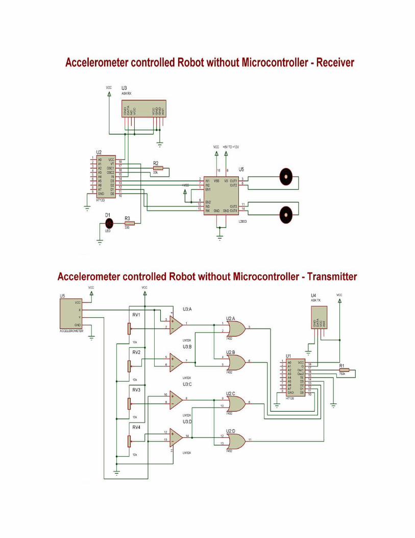
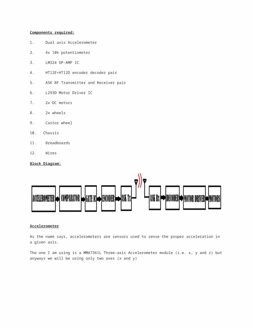
Block Diagram:
Accelerometer
As the name says, accelerometers are sensors used to sense the proper acceleration in a given axis.
The one I am using is a MMA7361L Three-axis Accelerometer module (i.e. x, y and z) but anyways we
will be using only two axes (x and y)

These sensors give analog output proportional to the tilt angle or orientation. More about this later.
LM324 Op-Amp
LM324 consists of four operational amplifiers which we would use as comparators. One of the inputs of
each op-amp would be connected to the accelerometer’s output. And other inputs would be connected
to their respective potentiometers which would be tuned later to give the required digital output.
We need four different combinations (For Forward, backward, right and left)
Imagine your hand as the accelerometer. The direction your fingers point to is the positive Y direction
and opposite to it is the negative Y. Perpendicular to your fingers, X axis exists.

These are the four orientations we would be assigning:
Now at normal position (accelerometer parallel to ground), the X and Y outputs of the sensors gives a
fixed analog voltage. Read it using a multimeter. Below are the values I got from my sensor when in
normal position and then after tilting the sensor like above shown diagram.
TILT DIRECTION
VOLTAGE READING
(in Volts) NO TILT FORWARD BACKWARD RIGHT LEFT
X 1.65 NA NA 2.3 1.1
Y 1.65 2.2 1.1 NA NA
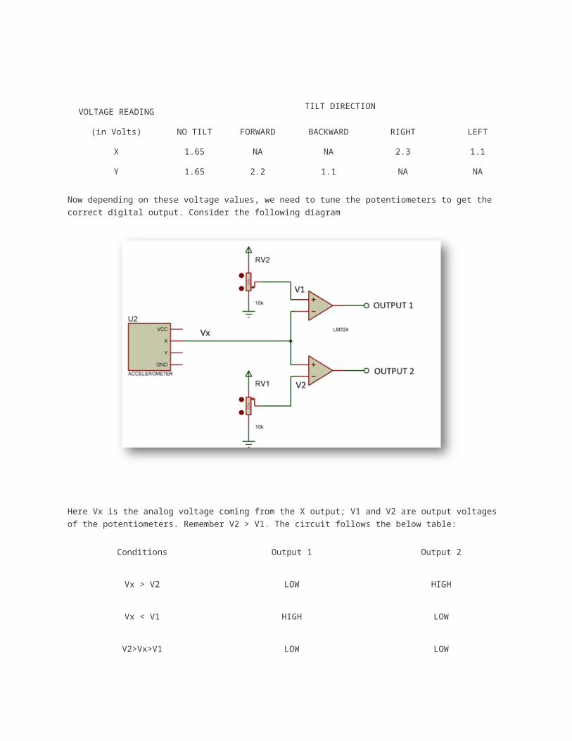
Now depending on these voltage values, we need to tune the potentiometers to get the correct digital
output. Consider the following diagram
Here Vx is the analog voltage coming from the X output; V1 and V2 are output voltages of the
potentiometers. Remember V2 > V1. The circuit follows the below table:
Conditions Output 1 Output 2
Vx > V2 LOW HIGH
Vx < V1 HIGH LOW
V2>Vx>V1 LOW LOW
So we need to adjust V1, V2 values (using the potentiometer) based on the reading we got and the above table.
You can see a demonstration in the video at the end. I connected LEDs to the output pins to see its state.
Similarly we do for Y output also.
Then we would get the below 4-bit output from the LM324 IC:
Tilt DirectionO1 O2
O
3O4
FORWARD 1 0 0 0
BACKWARD 0 1 0 0
RIGHT 0 0 1 0
LEFT 0 0 0 1
For Encoder/Decoder and RF ASK transmitter/Receiver, refer this
tutorial: http://www.engineersgarage.com/electronic-circuits/dc-motor-control-circuit-wireless-rf
Motor Driver
We will be using L293D motor driver which can control two motors bi-directionally. The reason we use
a motor driver is because circuits (most of them)/ microcontroller work at a different voltage level
when compared to the motor and also they cannot provide enough current to the motors. L293D has 4
inputs and 4 output terminals. Here is a table showing the input combinations and corresponding
outputs.
INPUTS MOTOR DIRECTION ROBOT’S MOTION
I1I2 I3 I4 LEFT MOTOR RIGHT MOTOR
10 0 1 ANTI CLOCKWISE CLOCKWISE FORWARD
01 1 0 CLOCKWISE ANTI CLOCKWISE BACKWARD
10 1 0 ANTI CLOCKWISE ANTI CLOCKWISE RIGHT
01 0 1 CLOCKWISE CLOCKWISE LEFT
: http://www.engineersgarage.com/electronic-circuits/dc-motor-control-circuit-wireless-rf
Wireless remote controlled toy cars work on the concept explained in this project. Motor
control through RF communication is a very interesting application and is widely used
in robotics, electronics toys, automation systems etc. This topic covers the way DC
motors can be driven by using the controls from a distant place. The controls are
transferred from one end to another by employing an RF module.

The remote control application of RF has been extended to operate a motor driver
which in turn controls the direction of motors.
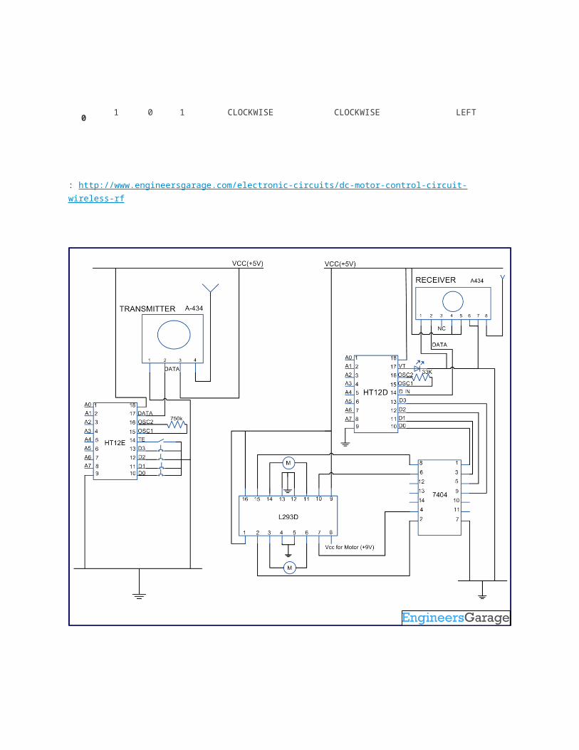
The circuit of this project uses RF module to control DC motors through a motor driver IC L293D. Transmission is enabled by giving a low bit to pin14 (TE, active low) of encoder HT12E. The controls for motor are first sent to HT12E. Pins 10 and 11 (D0-D1) are used to control one motor while pins 12 and 13 (D2-D3) to control another motor. The data signals of encoder HT12E work on negative logic. Therefore a particular signal is sent by giving a low bit to the corresponding data pin of encoder.
The parallel signals generated at transmission end are first encoded (into serial format)
by HT12E and then transferred through RF transmitter (434 MHz) at a baud rate of
around 1-10 kbps. The same signals are acquired by RF receiver after which it is
decoded by HT12D. For more details, refer RF remote control.
Since the encoder/decoder pair used here works on negative logic, the decoded signals
are fed to an inverter (NOT gate) IC 74LS04. The proper (inverted) signals are then
supplied to L293D. L293D contains two inbuilt H-bridge driver circuits to drive two DC
motors simultaneously, both in forward and reverse direction.
The motor operations of two motors can be controlled by input logic at pins 2 & 7 and
pins 10 & 15. Input logic 00 or 11 will stop the corresponding motor. Logic 01 and 10 will
rotate it in clockwise and anticlockwise directions, respectively. Thus, depending upon
the signals generated at the transmission end, the two motors can be rotated in desired
directions.
155,564-Reads
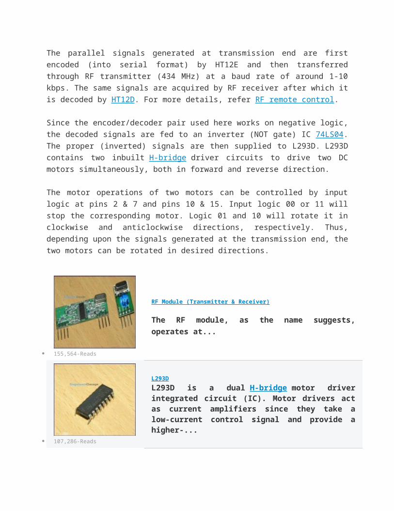
RF Module (Transmitter & Receiver)
The RF module, as the name suggests, operates at...
107,286-Reads
L293D
L293D is a dual H-bridge motor driver integrated circuit (IC). Motor drivers act as current amplifiers since they take a low-current control signal and provide a higher-...
67,059-Reads
IC 74LS04
7404 is a NOT gate IC. It consists of six inverters which perform logical invert action. The...
HT12E Encoder IC
HT12E is an encoder integrated circuit of 212 ...

60,144-Reads
46,140-Reads
HT12D Decoder IC
HT12D is a decoder integrated circuit that belongs to 212 series of decoders. This series of decoders...
How to lock the folder without any software?Sometimes when we are working on a shared computer or we have some confidential
data that we want to protect it from accessing the other users. A lot of softwares are
available for this purpose. But do you know that you can simply create a locked folder in
your computer without any software and you will have a key that will be required to
unlock that folder. There are two of methods discussed here, to exercise the first one
simply follow these steps:
1. First create a folder in any drive, let’s do as F:/Mouse (It will be better to create a
folder with name similar to the name of folders in Control Panel as on clicking the locked
folder, it will redirect to the control panel).
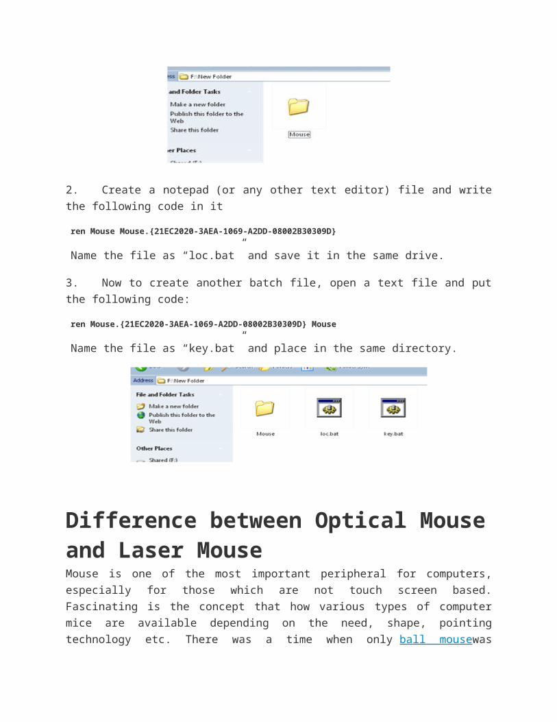
2. Create a notepad (or any other text editor) file and write the following code in it
ren Mouse Mouse.{21EC2020-3AEA-1069-A2DD-08002B30309D}
Name the file as “loc.bat” and save it in the same drive.
3. Now to create another batch file, open a text file and put the following code:
ren Mouse.{21EC2020-3AEA-1069-A2DD-08002B30309D} Mouse
Name the file as “key.bat” and place in the same directory.
Difference between Optical Mouse and Laser MouseMouse is one of the most important peripheral for computers, especially for those which
are not touch screen based. Fascinating is the concept that how various types of
computer mice are available depending on the need, shape, pointing technology etc.
There was a time when only ball mousewas prevalent. A proper surface was needed to
make it work and regular cleaning was mandatory too. Then came in the optical
technology giving us LED and laser based mice which, now has removed the barriers of
wiring too. These optical mice are now the present and probably future of this palm
sized computer peripheral. This article would detail with difference between a general
optical mouse and its sub-type, a Laser mouse. Obviously, both these mice are
based on light based tracking method but stand apart when detailed in numerous other
terms.
1. Technology Inception: Optical mouse technology was invented in the year 1980
but it took almost 2 decades to get to the commercial success threshold. Laser mouse
was first seen in Sun computers’ servers and workstations. It was launched for day to
day computing purposes in the year 2004 by Logitech.
2. Light Source: Optical mouse can use LED or an array of photodiodes as their light
source. Laser mice use infra red laser sources which are invisible to the naked eye.
However, when photographed using a CCD sensor, a purple can be seen in the image.
As Laser and optical mouse would appear similar in their appearance, one can figure
out the difference only by turning them upside down and comparing their light sources.
Optical mice usually have a red, white or even blue colored light coming out of them
whereas laser mice will have an infrared source which usually is not visible.
3. Button Functionality: Optical mice come with a manufacturer setting of two buttons
and one scrolling wheel or three buttons. Laser mice, on the other hand, carry much more functionality features as they have extra buttons which can be programmed by the user. The number of buttons on a laser mouse can go as many as 12.
4. DPI and Mouse Sensitivity: Dots per inch (DPI) is a measure of mouse sensitivity. It
can be defined as the number of movements the mouse can sense when it is moved

one inch. The higher the DPI of a mouse, more sensitive the mouse pointer would be.
The user can then expect more precise and accurate mouse-pointer experience.
5. Generally laser mice are known to show a fairly high DPI than other optical mice. An
optical mouse is known to show DPI of upto 800 while laser mouse support DPI’s
anywhere between 2000 and 3400. A few laser mice also allow DPI variations.
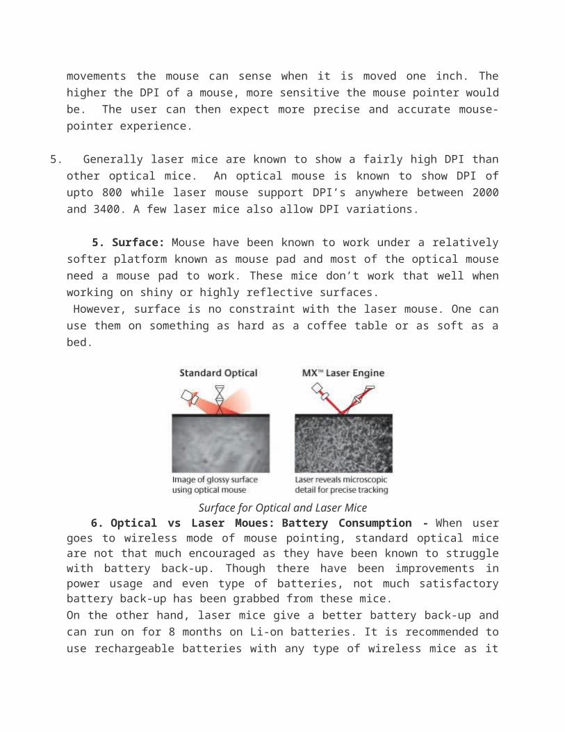
5. Surface: Mouse have been known to work under a relatively softer platform known
as mouse pad and most of the optical mouse need a mouse pad to work. These mice
don’t work that well when working on shiny or highly reflective surfaces.
However, surface is no constraint with the laser mouse. One can use them on
something as hard as a coffee table or as soft as a bed.
Surface for Optical and Laser Mice 6. Optical vs Laser Moues: Battery Consumption - When user goes to wireless mode
of mouse pointing, standard optical mice are not that much encouraged as they have been known to struggle with battery back-up. Though there have been improvements in power usage and even type of batteries, not much satisfactory battery back-up has been grabbed from these mice.
On the other hand, laser mice give a better battery back-up and can run on for 8 months
on Li-on batteries. It is recommended to use rechargeable batteries with any type of
wireless mice as it would be more economical and better battery life would be possible.
7. Optical vs Laser Mouse: User Experience - Optical mouse has definitely proved itself as a
much improved version over the mechanical mouse. However, it cannot take down the supremacy that laser mouse has established in terms of user experience. As the screen for the computer sizes up to 17inches and even larger sizes, it is desired that the mouse gives a good DPI. Here, Laser mice are always preferred than the simple optical ones. Also, laser mice are popular among gamers for their high precision and added hardware feature of extra buttons.
8. Optical vs Laser Mouse Pricing: Both mice are available in economic prices but
when one goes towards high end mice which are designed specifically for gaming, he
would find laser mice normally. Apart from the laser based navigation technology, laser
mice have a better plastic body which can be covered by Teflon and other non sticky
coatings which promotes longer use. Moreover, the DPI can be changed as per the
output screen.
9. Optical vs Laser Moues Applications: Optical mice are more of general task mice
which suffice enough to be used at homes, office and schools. When the user adapts to
a larger screen or wants to work on graphics or wants to play high-end video games, it
is more probable for he would use a laser mouse. Laser mice are also available with
several modifications such as different surface texture, including a separate trackball
etc. Some laser mice are also developed in a game specific manner where user can
play the game using just a mouse.
Difference between 2G and 3G TechnologySecond Generation (2G) technology was launched in the year 1991 in Finland. It is based on the technology known as global system for mobile communication or in short we can say GSM. This technology enabled various networks to provide services like text messages, picture messages and MMS. In this technology all text messages are digitally encrypted due to which only the intended receiver receives message. These digital signals consume less battery power, so it helps in saving the battery of mobiles.
The technologies used in 2G are either TDMA (Time Division Multiple Access) which
divides signal into different time slots or CDMA (Code Division Multiple Access) which
allocates a special code to each user so as to communicate over a multiplex physical
channel.
3G technology generally refers to the standard of accessibility and speed of mobile
devices. It was first used in Japan in the year 2001. The standards of the technology
were set by the International Telecommunication Union (ITU). This technology enables
use of various services like GPS (Global Positioning System), mobile television
and video conferencing. It not only enables them to be used worldwide, but also
provides with better bandwidth and increased speed.
This technology is much more flexible as it can support 5 major radio technologies that
operate under CDMA, TDMA and FDMA. CDMA accounts for IMT-DS (direct speed),
IMT-MC (multi carrier). TDMA holds for IMT-TC (time code), IMT-SC (single carrier).
This technology is also comfortable to work with 2G technologies. The main aim of this
technology is to allow much better coverage and growth with minimum investment.
Figure: Evolution of Mobile system from 2G to 3G

Difference between 2G and 3G Technology
· Cost: The license fee to be paid for 3G network is much higher as compared to
2G networks. The network construction and maintenance of 3G is much costlier than
2G networks. Also from the customers point of view the expenditure for 3G network will
be excessively high if they make use of the various applications of 3G.
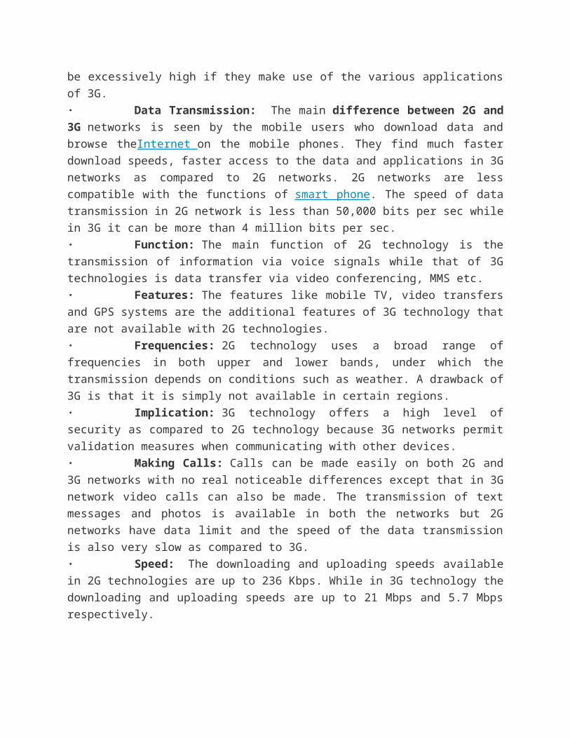
· Data Transmission: The main difference between 2G and 3G networks is
seen by the mobile users who download data and browse theInternet on the mobile
phones. They find much faster download speeds, faster access to the data and
applications in 3G networks as compared to 2G networks. 2G networks are less
compatible with the functions of smart phone. The speed of data transmission in 2G
network is less than 50,000 bits per sec while in 3G it can be more than 4 million bits
per sec.
· Function: The main function of 2G technology is the transmission of information
via voice signals while that of 3G technologies is data transfer via video conferencing,
MMS etc.
· Features: The features like mobile TV, video transfers and GPS systems are the
additional features of 3G technology that are not available with 2G technologies.
· Frequencies: 2G technology uses a broad range of frequencies in both upper
and lower bands, under which the transmission depends on conditions such as weather.
A drawback of 3G is that it is simply not available in certain regions.
· Implication: 3G technology offers a high level of security as compared to 2G
technology because 3G networks permit validation measures when communicating with
other devices.
· Making Calls: Calls can be made easily on both 2G and 3G networks with no
real noticeable differences except that in 3G network video calls can also be made. The
transmission of text messages and photos is available in both the networks but 2G
networks have data limit and the speed of the data transmission is also very slow as
compared to 3G.
· Speed: The downloading and uploading speeds available in 2G technologies are
up to 236 Kbps. While in 3G technology the downloading and uploading speeds are up
to 21 Mbps and 5.7 Mbps respectively.

Difference between Bluetooth and WiFiCommunication is going wireless with the upsurge of smart mobile devices such as
laptops, cellular phones, PDA, tablets etc. In order escape traps of wires and to stream
data wirelessly among these devices, a number of protocols have been formulated such
Bluetooth, Wi-Fi, NFC etc. Using these technologies users can exchange almost all
sorts of files at high speeds. The speed of data transfer is not a major concern and
there is no limit on data size exchanged. Though used for a lot of similar applications,
these data exchange protocols have significantly different rule stacks and vary a lot in
terms of range, device application etc. This article will detail with some of the common
and uncommon differences between two such data exchange protocols: Wi-Fi and
Bluetooth.
{C 1. Bluetooth vs. WiFi - Formulation: Bluetooth Technology’s invention has been
credited to Ericsson which in the year 1994 launched it as a wireless communication
alternative to RS232. Wi-Fi, though had researches since the mid 80s, was officially
launched in the year 1997. A committee for development of Wi-Fi was set in the year
1990 which was head by, Victor Hayes who is also known as father of Wi-Fi.
2. Bluetooth vs. WiFi - IEEE Standards: Bluetooth was initially defined under IEEE 802.15.1 standard
but is now taken care by a Special Interest Group (SIG). Wi-Fi, on the other hand, is defined under
802.11.x (x=a, b, c, and so on) series of protocols and is currently maintained under the same. A Wi-Fi
alliance founded by various companies tests and authorizes gadgets to be Wi-Fi compatible.
{C 3. Bluetooth vs. WiFi - Versions: Since its inception, Bluetooth has seen several versions of it such as
Bluetooth 2.0, Bluetooth 2.1, Bluetooth 3.0 and the latest, Bluetooth 4.0. Added technologies such as
Enhanced Data Rate (EDR), Alternate MAC/PHY, low energy protocols etc have been implemented in
these updates.
Various versions and upgrades are there in Wi-Fi too which are quite different than
those in Bluetooth. Since, it is an IEEE 802.11 standard, Wi-Fi versions are termed as
802.11.a, 802.11b and so on. These versions vary in terms of security protocols, radio
frequency used for data exchange, maximum speed for data exchange, bandwidth
occupied etc.
4. Bluetooth vs. WiFi - .Frequency: Bluetooth works at 2.4GHz frequency while Wi-Fi based networks
work at 2.4, 3.6 and 5 GHz .
5. Bluetooth vs. WiFi - Data Transfer Rates: The latest additions to Bluetooth (Bluetooth 4.0)
promises data transfer rates to be upto 25mbps while latest Wi-Fi version of Wi-Fi direct can reach upto
250mbps of data transferring rate. Earlier versions of Bluetooth were able to deliver data at 800 hops per
second while Wi-Fi clocked up at speeds like 54mbps.
{ 6. Bluetooth vs. WiFi - Range: Maximum range for Bluetooth based wireless connections is 30m while
for Wi-Fi, it can extend well upto 100m. In Wi-Fi, range depends on the version of Wi-Fi protocol applied
and addition of antennas in the communication system while no such concerns of range or extra antenna
are much known in Bluetooth.
. Bluetooth vs. WiFi - Devices Connected: In Bluetooth, upto 7 devices can be connected to each other
(piconet) while in Wi-Fi, the maximum connections depend on Wi-Fi router which can accommodate 1 to
several communicating devices at a time.
{C 8. Bluetooth vs. WiFi - Connection Complexity: Connecting two devices over Bluetooth is fairly simple
as there is just a simple key matching process. On the other hand, connections concerning Wi-Fi need an
expertise in configuration and security pass code matching process. This makes Wi-Fi connection
process more complex than the Bluetooth ones.
{C} 9. Bluetooth vs. WiFi - Security: Earlier versions of Bluetooth were encryption and even now Bluetooth
security is limited to key matching. Whereas in Wi-Fi, the security standards have been raised with
inclusion of new versions. Wireless Equivalent Privacy (WEP) and Wi-Fi Protected Access (WPA) are two
most used security accesses used in Wi-Fi with the former being less secure than the latter.
{C 10. Bluetooth vs. WiFi - Power Consumption: Able to works at longer distances and loaded with high
quality security protocols makes Wi-Fi a more power consuming protocol than Bluetooth.
{C11. Bluetooth vs. WiFi - Applicative Scenario: Wi-Fi technology is more used in connecting computers
to routers or internet gateways. Moreover, a number of electronic gadgets such as camera, gaming
consoles, PDA’s etc. also make use of Wi-Fi to connect to each other or internet.
Bluetooth, on the other hand, is used to connect peripherals to the computer. Computer
keyboards, mouse, headsets etc. can be connected to the CPU using Bluetooth
protocol.

Difference Between Compiler and InterpreterA Compiler and Interpreter both carry out the same purpose – convert a high level language (like C, Java) instructions into the binary form which is understandable by computer hardware. They are the software used to execute the high level programs and codes to perform various tasks. Specific compilers/interpreters are designed for different high level languages. However both compiler and interpreter have the same objective but they differ in the way they accomplish their task i.e. convert high level language into machine language. Through this article we will talk about the basic working of both and distinguish the basic difference between compiler and interpreter.
Compiler
A compiler is a piece of code that translates the high level language into machine
language. When a user writes a code in a high level language such as Java and wants
it to execute, a specific compiler which is designed for Java is used before it will be
executed. The compiler scans the entire program first and then translates it into
machine code which will be executed by the computer processor and the corresponding
tasks will be performed.
Shown in the figure is basic outline of the compilation process, here program written in
higher level language is known as source program and the converted one is called
object program.
Interpreter
Interpreters are not much different than compilers. They also convert the high level
language into machine readable binary equivalents. Each time when an interpreter gets
a high level language code to be executed, it converts the code into an intermediate
code before converting it into the machine code. Each part of the code is interpreted
and then execute separately in a sequence and an error is found in a part of the code it
will stop the interpretation of the code without translating the next set of the codes.

Outlining the basic working of the interpreter the above figure shows that first a source
code is converted to an intermediate form and then that is executed by the interpreter.
The main differences between compiler and interpreter are listed below:
· The interpreter takes one statement then translates it and executes it and then
takes another statement. While the compiler translates the entire program in one go and
then executes it.
· Compiler generates the error report after the translation of the entire page while
an interpreter will stop the translation after it gets the first error.
· Compiler takes a larger amount of time in analyzing and processing the high level
language code comparatively interpreter takes lesser time in the same process.
· Besides the processing and analyzing time the overall execution time of a code is
faster for compiler relative to the interpreter.