robotic non destructive testing sattar, t.p.1, leon
TRANSCRIPT
Sattar Page 1 of 21
26th International Conference of CAD/CAM, Robotics & Factories of the Future 26-28 July 2011, Kuala Lumpur, Malaysia
ROBOTIC NON DESTRUCTIVE TESTING
Sattar, T.P.1, Leon Rodriguez, H.E.2, Salman, H.1 1 London South Bank University, Faculty of Engineering, Sceince & the Built
Environment, London, UK
e-mail: [email protected] 2 Nueva Granada Military University, Bogota, Colombia
ABSTRACT
This keynote paper aims to highlight the application of mobile robotics to perform inspection
and Non Destructive Testing (NDT) in industries such as aerospace, large scale fabrication,
pipelines, petro-chemical storage, and power generation. It describes industrial tasks where
regular inspection is essential to ensure the integrity of infrastructure such as storage tanks,
pressure vessels, pipelines, aircraft, ships, etc, and to provide managers of capital assets with
data to plan outages and to make decisions on the life span of their infrastructure. The
development of robot prototypes is described for these industrial tasks. These robots deploy
NDT systems by first providing access to large vertical structures or to test sites that are
inaccessible to humans. They are designed to reduce outage time, or where possible, carry
out the NDT on-line thus preventing costly outages.
Keywords: Non Destructive Testing, Wall Climbing, Pipe Climbing and Amphibious Robots.
1 INTRODUCTION
Robotic Non Destructive Testing (RNDT) is a field that has made some progress over the past two decades [1,2]. The aim is to combine robotics with non destructive testing and evaluation techniques to enable an operator to perform inspection remotely. The 4 essential Ms of RNDT are Monitoring, Mobility, Manipulation and Measurement. Monitoring is the task of obtaining and storing information (data from previous inspection) about safety critical infrastructure to make asset management and outage decisions. Mobility is the task of carrying a payload of NDT sensors to a test site on very large structures that may also be located in hazardous environments. Manipulation is the task of deploying the NDT sensors in the required way e.g. raster scanning, following weld lines, skewing a probe to get higher signal to noise ratio, etc. Finally, the Measurement task is to reliably detect the presence and size of defects such as corrosion, cracks, inclusions, and disbonding in laminate structures. Regulatory bodies require mandatory inspection of safety critical infrastructure both during and after construction. These structures are usually very large and/or located in remote and hazardous environments. The Non Destructive Testing (NDT) system has to be deployed by first providing very expensive access, requiring the erection of scaffolding and lengthy preparation before NDT can start. In many cases e.g. in power plant, pipelines, storage tanks in the petro-chemical and food processing industries, etc., the inspection has to be performed during an outage by shutting down a plant. There is enormous pressure to reduce the outage time by performing the inspections as efficiently and quickly as possible to provide a quick turnaround. Our research has developed a number of mobile wall-climbing, swimming and pipe-
climbing robots that greatly reduce the cost of access to a test site by eliminating
Sattar Page 2 of 21
26th International Conference of CAD/CAM, Robotics & Factories of the Future 26-28 July 2011, Kuala Lumpur, Malaysia
scaffolding or abseiling and rope deployment of human operators [3]. This paper
describes some of these robots.
Probably the World’s first wall climbing robot was developed in the late 1980’s by the
Institute of Problems in Mechanics, Moscow. The robot uses two platforms that move
relative to each other to obtain stepped motion. The platforms attach to a surface using
pneumatic suction cups. A rotation of the outer platform (while the inner platform is
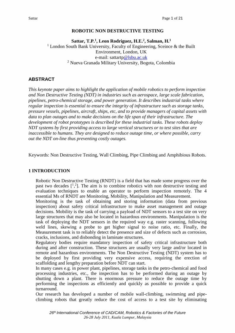
attached to a surface) enables change of direction. We modified this robot in 1992 by
equipping it with a six axis robot arm and an ultrasound flaw detector to perform the
NDT of vertical steel plates. The modified robot is shown in figure 1(a). Figure 1(b) shows the RRNDT wall climbing robot that we developed in 1995[4,5]. The robot uses pneumatic suction cups to stick to a surface. It carries a six axis PUMA 260 arm to raster scan with wet and dry contact ultrasound probes. The figure shows a C-scan image of corrosion thinning (variable thickness 0-6 mm measured from the back wall) of a 10mm thick steel plate, adjacent colors corresponding to thickness steps of 0.375 mm. Data obtained with 5 MHz wet contact compression wave probe (8mm diameter). The C-scan image is of the letter “U” which is part of the word “SBU” that is machined into the back of the 10mm thick steel plate.
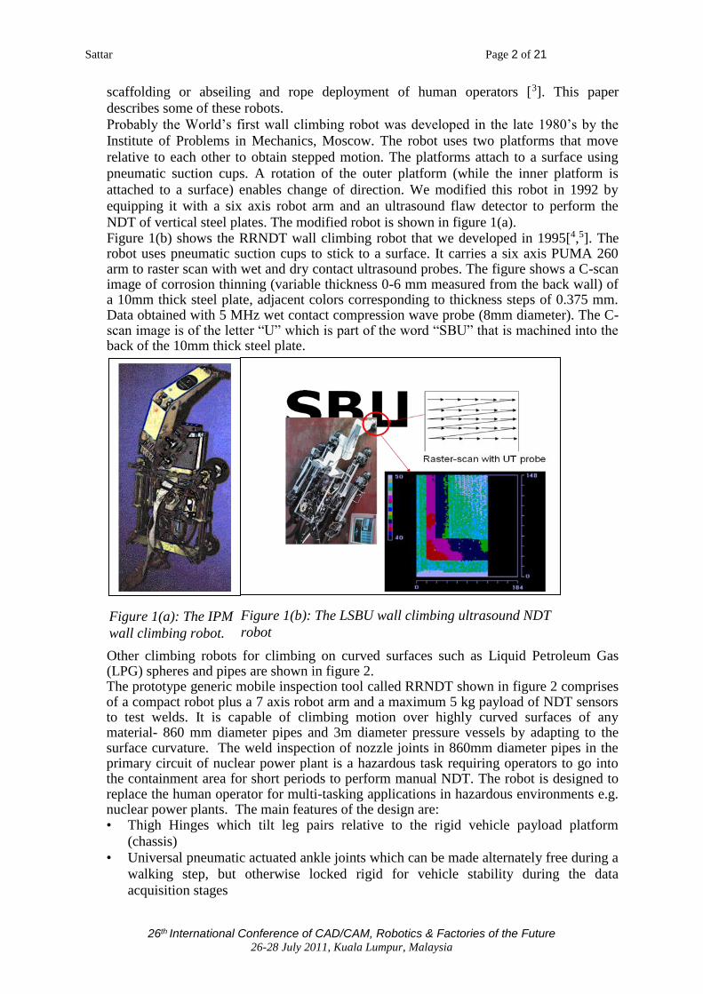
Other climbing robots for climbing on curved surfaces such as Liquid Petroleum Gas (LPG) spheres and pipes are shown in figure 2. The prototype generic mobile inspection tool called RRNDT shown in figure 2 comprises of a compact robot plus a 7 axis robot arm and a maximum 5 kg payload of NDT sensors to test welds. It is capable of climbing motion over highly curved surfaces of any material- 860 mm diameter pipes and 3m diameter pressure vessels by adapting to the surface curvature. The weld inspection of nozzle joints in 860mm diameter pipes in the primary circuit of nuclear power plant is a hazardous task requiring operators to go into the containment area for short periods to perform manual NDT. The robot is designed to replace the human operator for multi-tasking applications in hazardous environments e.g. nuclear power plants. The main features of the design are: • Thigh Hinges which tilt leg pairs relative to the rigid vehicle payload platform
(chassis)
• Universal pneumatic actuated ankle joints which can be made alternately free during a
walking step, but otherwise locked rigid for vehicle stability during the data
acquisition stages
Figure 1(b): The LSBU wall climbing ultrasound NDT
robot Figure 1(a): The IPM
wall climbing robot.
Sattar Page 3 of 21
26th International Conference of CAD/CAM, Robotics & Factories of the Future 26-28 July 2011, Kuala Lumpur, Malaysia
• Suction feet which can adapt and adhere to curved surfaces whilst remaining
sufficiently rigid for vehicle stability
• Seven degrees of freedom revolute jointed arm equipped with a force sensor in its
wrist and a 5MHz ultrasound probe.
The RRNDT robot has been tested on ultrasonic examination of welds on a 350mm
nozzle at 45 degrees to 865 mm diameter feeder pipes in the reactor coolant loop of a
nuclear power station, Sizewell B, United Kingdom.
2 WELD INSPECTION OF SHIP HULLS AND STRENGTHENING PLATES
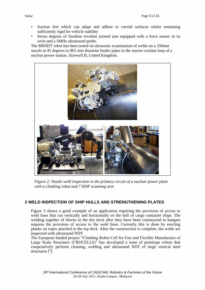
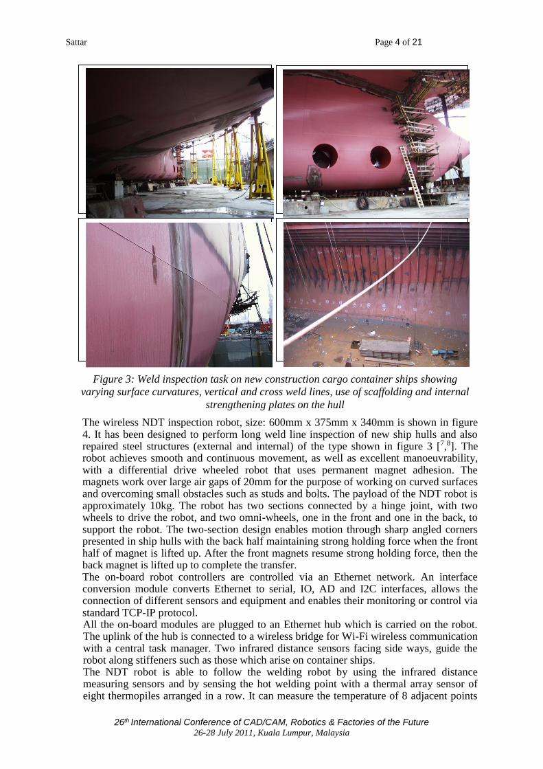
Figure 3 shows a good example of an application requiring the provision of access to weld lines that run vertically and horizontally on the hull of cargo container ships. The welding together of blocks in the dry dock after they have been constructed in hangars requires the provision of access to the weld lines. Currently this is done by erecting planks on ropes attached to the top deck. After the construction is complete, the welds are inspected with ultrasound NDT. The European funded project “Climbing Robot Cell for Fast and Flexible Manufacture of Large Scale Structures (CROCELLS)” has developed a team of prototype robots that cooperatively perform cleaning, welding and ultrasound NDT of large vertical steel structures [6].
Figure 2: Nozzle weld inspection in the primary circuit of a nuclear power plant
with a climbing robot and 7 DOF scanning arm
Sattar Page 4 of 21
26th International Conference of CAD/CAM, Robotics & Factories of the Future 26-28 July 2011, Kuala Lumpur, Malaysia
The wireless NDT inspection robot, size: 600mm x 375mm x 340mm is shown in figure 4. It has been designed to perform long weld line inspection of new ship hulls and also repaired steel structures (external and internal) of the type shown in figure 3 [7,8]. The robot achieves smooth and continuous movement, as well as excellent manoeuvrability, with a differential drive wheeled robot that uses permanent magnet adhesion. The magnets work over large air gaps of 20mm for the purpose of working on curved surfaces and overcoming small obstacles such as studs and bolts. The payload of the NDT robot is approximately 10kg. The robot has two sections connected by a hinge joint, with two wheels to drive the robot, and two omni-wheels, one in the front and one in the back, to support the robot. The two-section design enables motion through sharp angled corners presented in ship hulls with the back half maintaining strong holding force when the front half of magnet is lifted up. After the front magnets resume strong holding force, then the back magnet is lifted up to complete the transfer. The on-board robot controllers are controlled via an Ethernet network. An interface conversion module converts Ethernet to serial, IO, AD and I2C interfaces, allows the connection of different sensors and equipment and enables their monitoring or control via standard TCP-IP protocol. All the on-board modules are plugged to an Ethernet hub which is carried on the robot. The uplink of the hub is connected to a wireless bridge for Wi-Fi wireless communication with a central task manager. Two infrared distance sensors facing side ways, guide the robot along stiffeners such as those which arise on container ships. The NDT robot is able to follow the welding robot by using the infrared distance measuring sensors and by sensing the hot welding point with a thermal array sensor of eight thermopiles arranged in a row. It can measure the temperature of 8 adjacent points
Figure 3: Weld inspection task on new construction cargo container ships showing
varying surface curvatures, vertical and cross weld lines, use of scaffolding and internal
strengthening plates on the hull

Sattar Page 5 of 21
26th International Conference of CAD/CAM, Robotics & Factories of the Future 26-28 July 2011, Kuala Lumpur, Malaysia
simultaneously. The sensor reads infra-red in the 2um to 22um range, which is the radiant heat wavelength. The driving wheels are made of aluminium hubs bonded with solid 65
IRHD polyurethane tyres with coefficient of friction of 0.9 on steel walls. The key benefits of the material are resistance to abrasion (non-marking), impact, cuts, and large range of operating temperatures. The polyurethane material has a long working life, good traction and is oxygen and ozone resistant. The NDT robot is required to perform real time inspection of long weld lines with 100%
volume coverage, simultaneously with the welding process. Ultrasound phased array
NDT with an Omniscan carried by the robot sends data wirelessly to a laptop for analysis.
A scan from a weld test piece is shown in figure 5.
Figure 4: The CROCELLS wall climbing robots performing both
welding and weld inspection
Weld defect visible
on phased array scan
Figure 5: Weld NDT with phased array ultrasound
Sattar Page 6 of 21
26th International Conference of CAD/CAM, Robotics & Factories of the Future 26-28 July 2011, Kuala Lumpur, Malaysia
3. INSPECTION OF AIRCRAFT WINGS AND FUSELAGE
Regular NDT of civil aircraft is mandatory. Aircraft wings and fuselage are tested for
bond quality, corrosion, impact damage, and cracks around fastener holes. Pressurisation
and de-pressurisation during takeoff/landing cycle causes stress fatigue at the rivets that
hold the surface skin to its frame. The fatigue results in growth of radial cracks. There are
approximately 2,000 rivets in a typical aircraft wing. NDT is mostly manual with limited
area coverage. Techniques used are eddy current, ultrasonic and X-ray. The inspection is
unreliable due to operator fatigue when performing100% inspection on large structures
e.g. aerofoil and wings. Full coverage with more reliable methods such as X-ray is very
expensive as the component has to be removed for radiography in shielded bays.
Robotic deployment of the NDT techniques offers three operational and economic
advantages: thoroughness, correctness, and records of the inspection.
Portable C-scanner bridges, fixed by straps or suction cup, are available for semi-
automation of ultrasonic field inspection enabled by Microelectronics and PC
development. Flexible bridges have been introduced in recent years to deal with the
complex geometry of aircraft structures e.g. PANDA (Tektrend, Quebec), MAUS
(Boeing, St Louis), and the ISCAN (Fraunhofer Institute, Germany).
Automated Non Destructive Inspector (ANDI) [Carnegie Mellon University], The Crown
Inspection Mobile Platform (CIMP) [Carnegie Mellon University], The Autocrawler
[AutoCrawler LLC] and the Multifunction Automated Crawling System (MACS), NASA
Jet Propulsion Laboratory.
Our climbing robot called ROBAIR [9] provides access to the top-side and under-side of
aircraft wings and fuselage. The compact robot uses vacuum adhesion to adhere to a
surface to climb on the topside and underside of aircraft wings and on all areas of the
fuselage. It can carry a 18 kg payload of scanning arm plus NDT Sensors with a safety
factor of 4, move over all surfaces with curvatures less than 0.3m and travel with a
maximum speed of 1m/min. The mass of the climbing robot is 20kg with outer
dimensions 518x518x180mm. Payload including umbilical mass is 18 kg. The umbilical
comprises of two 10mm air tubes, 2 twisted pairs RS485, a 2 wire cable for 24VDC. The
climbing ability is proven on test frames.
Non-Destructive Evaluation Sensors and Instrumentation
The climbing vehicle carries a Flaw Detector and the scanning arm carries a sensor
payload that is changed according to inspection requirements and comprises of a Acoustic
Camera, Ultrasonic Phased Array, Eddy Current sensor, Thermo graphic Camera,
Ultrasonic Dry Contact Wheel Probes and Defect Visualization Software.
Ultrasonic wheel probes constructed of hydrophilic material have been shown to be
capable of detecting rivet defects and the Phased array has been shown capable of
detecting angled cracks.
The Thermo graphic technique is best at detecting loose rivets while Eddy-current
detection of angled cracks has been successfully demonstrated.
Robotic Scanner Mounted on the climbing vehicle is a Cartesian scanning arm with 4 degrees of freedom
(X, Y, Z and Roll) that deploys NDT sensors in a work envelope of volume 400 x 400 x
180 mm. Control systems adapt to the changing dynamics of the inspection device as it
operates on different structures e.g. on a fuselage or top or bottom of aircraft wing.

Sattar Page 7 of 21
26th International Conference of CAD/CAM, Robotics & Factories of the Future 26-28 July 2011, Kuala Lumpur, Malaysia
Figure 6: ROBAIR climbing robot inspecting rows of rivets on aircraft wings and
fuselage
Figure 7: Inspection of loose rivets with thermo graphy. The climbing robot
carrying a thermograph camera and heat source. Bottom: Loose rivet detected
Sattar Page 8 of 21
26th International Conference of CAD/CAM, Robotics & Factories of the Future 26-28 July 2011, Kuala Lumpur, Malaysia
4. INSPECTION OF STORAGE TANK FLOORS Storage tanks are normally inspected by opening them after every ten years. Tank outages
are very expensive as the tank product has to be emptied by transporting and storing it at
other locations. The tank has to be repeatedly cleaned so that it is free of toxic and
explosive vapour before the tank is opened for inspection by human operators. A crude
oil tank outage can take 8-9 months. Initial NDT is by MFL and more detailed inspection
is by ultrasound.
Huge savings in cost and inspection times could be obtained by performing in-service
inspection of tank floors and walls with robotic devices. Our work has resulted in the
development of prototype mobile robots [10] that can enter tanks through minimum
manhole openings of 300 mm diameter to deploy a payload of Non Destructive Testing
(NDT) sensors for the inspection of top and bottom corrosion on the tank floor. The
robots are designed to operate in explosive and hazardous liquids such as crude oil,
petroleum products, etc.
To inspect the floor of clean storage tanks (size from about 2 to 20 metres in diameter)
containing blended oil products and chemicals, for underside corrosion, magnetic flux
leakage (MFL) is used for the initial inspection. Suspect areas are further examined using
either vacuum box or magnetic particle inspection methods.
To inspect larger crude oil storage tanks (20 and 100 metres diameter with construction
from carbon steel and floating roofs), either double skin or pontoon type, with many
manhole openings (for agitator entry). The preparation periods for entry and internal
inspection are lengthy with 6-9 months required for removal of the oil, gas, and sludge
banks. Another 3-6 months are required for the process of washing the tank clean of all
oil and venting it before men can enter the tank. Tanks are inspected visually followed by
MFL techniques to find problem areas. Ultrasound testing is used as a final method to
validate the problem areas. Dependent on technique, annular floor plate thickness up to
35mm can be achieved with discrimination between topside and under floor corrosion. A
number of robots that gain entry to tanks to perform cleaning and inspection tasks have
been developed [11,12,13].
Our prototype wall climbing robot called ROBTANK [14] can perform ultrasonic non-
destructive testing (NDT) while submerged in liquids. The robot is able to rotate through
any angle within the full 360 degree maximum and can change surfaces from a floor to a
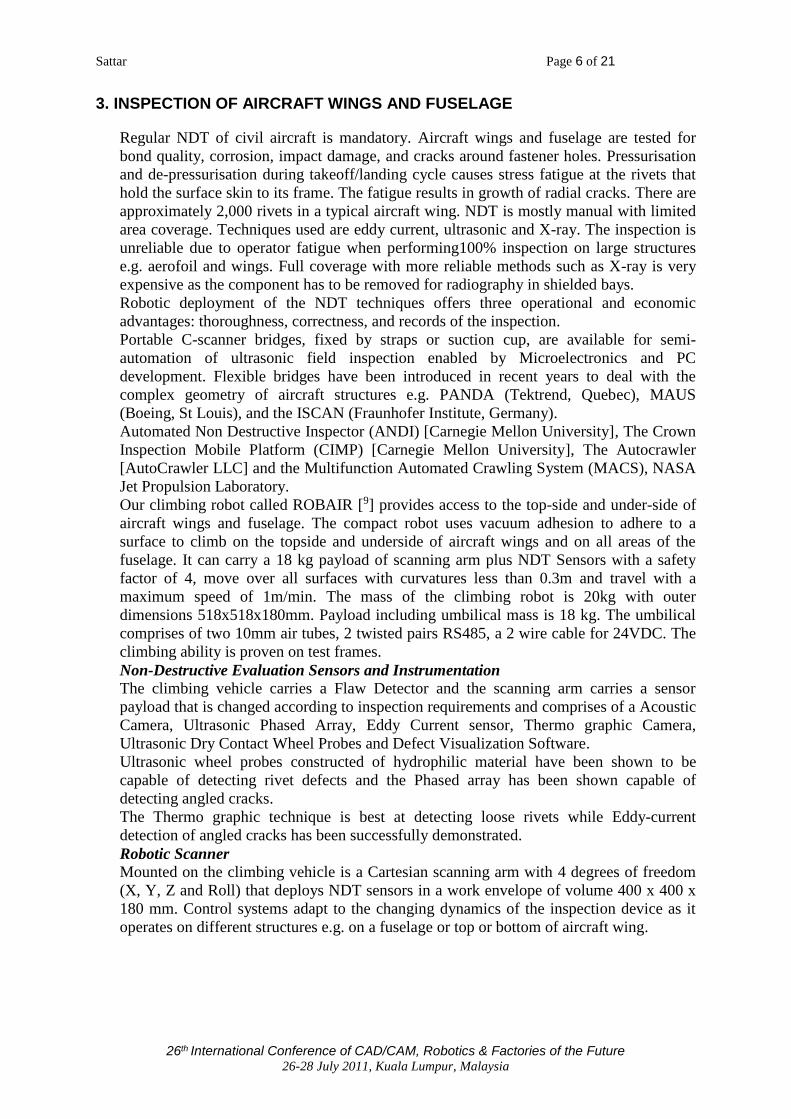
Figure 8: Other NDT methods to detect cracks between rivets. On the right: Phased
array ultrasound. On the right: Eddy current NDT detects slot between two rivets
Sattar Page 9 of 21
26th International Conference of CAD/CAM, Robotics & Factories of the Future 26-28 July 2011, Kuala Lumpur, Malaysia
wall and vice versa. It is designed to find application in the in-service inspection of large
storage tanks to detect corrosion on tank floors and walls, and in the inspection of
floating oil storage platforms that have first been emptied and then filled with water. It
can also be applied without modification to inspect the submerged hull of a ship.
ROBTANK is designed to be compact and lightweight so that it can be manually handled
by one or at most two operators and can be inserted into restricted spaces through
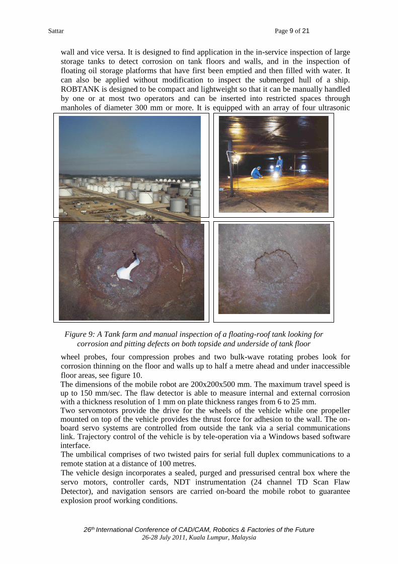
manholes of diameter 300 mm or more. It is equipped with an array of four ultrasonic
wheel probes, four compression probes and two bulk-wave rotating probes look for
corrosion thinning on the floor and walls up to half a metre ahead and under inaccessible
floor areas, see figure 10. The dimensions of the mobile robot are 200x200x500 mm. The maximum travel speed is up to 150 mm/sec. The flaw detector is able to measure internal and external corrosion with a thickness resolution of 1 mm on plate thickness ranges from 6 to 25 mm. Two servomotors provide the drive for the wheels of the vehicle while one propeller mounted on top of the vehicle provides the thrust force for adhesion to the wall. The on-board servo systems are controlled from outside the tank via a serial communications link. Trajectory control of the vehicle is by tele-operation via a Windows based software interface. The umbilical comprises of two twisted pairs for serial full duplex communications to a
remote station at a distance of 100 metres.
The vehicle design incorporates a sealed, purged and pressurised central box where the
servo motors, controller cards, NDT instrumentation (24 channel TD Scan Flaw
Detector), and navigation sensors are carried on-board the mobile robot to guarantee
explosion proof working conditions.
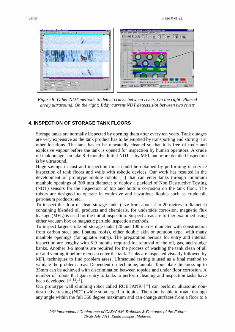
Figure 9: A Tank farm and manual inspection of a floating-roof tank looking for
corrosion and pitting defects on both topside and underside of tank floor
Sattar Page 10 of 21
26th International Conference of CAD/CAM, Robotics & Factories of the Future 26-28 July 2011, Kuala Lumpur, Malaysia
The vehicle is able to travel on the tank floor while submerged in liquid (tests have been
performed in water), change surfaces from the floor to a wall and vice versa, and climb
the walls of a tank. It uses thrust from two propellers to provide vehicle adhesion to a
vertical surface and hence is able to climb on all types of surface.
Figure 10: ROBTANK climbing a wall carrying a payload of NDT sensors
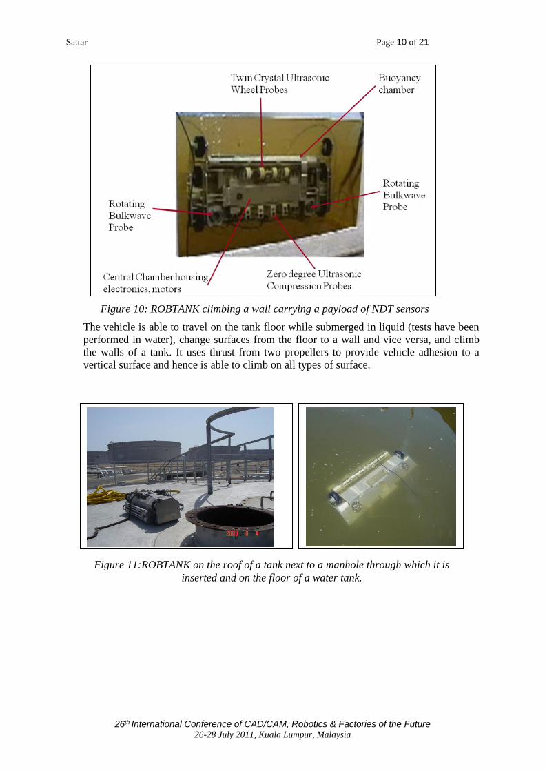
Figure 11:ROBTANK on the roof of a tank next to a manhole through which it is
inserted and on the floor of a water tank.

Sattar Page 11 of 21
26th International Conference of CAD/CAM, Robotics & Factories of the Future 26-28 July 2011, Kuala Lumpur, Malaysia
Two probe arrays, each 30cm long with 15 to 20mm pitch, are mounted to the front and
rear of the inspection robot. The minimum detectable area is a 6mm diameter flat-
bottomed hole at a range of 3 mm. A surface coverage of 3m2 per minute and surface
speed of 10 m per minute are realisable with this arrangement. The inspection system is
able to measure plate thickness between 6-25mm with minimum thickness of 3mm. Two
sets of 0º (in the front and rear of the vehicle) high efficiency twin wheel probes have
been developed to cope with large crude oil tank inspection difficulties and environment
conditions. They are designed to European Standard EN10160 (July 1999) for the UT
examination of steel planar plates. Tests on single and twin crystal probes for scanning
the surface with a fluid gap or direct contact, ability to monitor wall thickness despite
changes in probe orientation, size of probe, frequency of element and coverage, and the
influence of sludge, sand and other tank constituents resulted in the development of a
Wheel probe system consisting of a high efficiency ultrasonic inspection twin wheel
probe that in the preliminary laboratory tests showed a promising behaviour working in
crude oil tank environment simulations.
Two ultrasonic rotating bulk wave probes are mounted on the two sides of the robot to
speed up the discovery of potentially corroded areas in the plate with a look forward
distance of 50 cm in water. The probe is motorized and encoded to produce a radar type
B scan plot, see figure12, to detect the edges of tanks, welds, etc and can therefore be
180° 0°
B-Scan line with origin at centre
Drain outlet
Reflection of drain outlet in tank wall
Welded stud on tank floor
Top of tank wall
Tank floor weld
Corner of tank floor
Tank floor weld 270°
Figure 12: Floor inspection with rotating ROBULK ultrasound probes

Sattar Page 12 of 21
26th International Conference of CAD/CAM, Robotics & Factories of the Future 26-28 July 2011, Kuala Lumpur, Malaysia
used for navigation. The sound wave dives under unattached obstacles and can therefore
inspect under striker plates. Wheel probes that can penetrate debris and sludge on the tank
floor provide quantitative data at the required rate.
A commercially available TD-Scan 24 channel flaw detector with dimensions of
170x60x104 mm is mounted in the purged box on-board the robot. The TD-Pocket
integrates a pulser/receiver, A/D converter, encoder inputs (the requirement is for one bi-
directional input to describe forward/backward travel), and 2 unidirectional encoders to
control the LORUS probes). Software for data acquisition, display and analysis in all
standard NDT formats is provided. The TD Pocket uses TTL signals from one of the
robots incremental encoders to position stamp the NDT data.
An industrial version of RobTank, certified as intrinsically safe and able to perform
reliable NDT, could
• Save 80% of the average cost of inspecting a storage tank i.e. 56,000 Euro per
tank
• Provide, after a few days of in-service inspection, an initial indication of state of
the tank floor and buried tank walls
• Enable a tank operator to plan an outage for repair and could prevent a mandatory
10 year outage when floor has not suffered from corrosion.
5. INSPECTION OF TANKS FOR FLOATING PRODUCTION STORAGE OF OIL
The other robot that we have developed for operation in liquids in storage tanks is the
FPSO robot that is designed for inspecting tanks in off-shore oil operations - Floating
Production Storage of Oil (FPSO), see figure 13. FPSO provides access to welds on
stiffener plates inside oil storage tanks when the tank is either full of oil or emptied to the
last few centimetres. It performs non-destructive testing of the welds using a number of
NDT techniques. The robot is very compact, inserted through a manhole in the roof, and
is able to swim to a test site on the floor of the tank. It is able to follow welds all the way
along stiffener plates in a constrained space and find weld cracks and floor corrosion. It is
designed to be intrinsically safe in Explosive Environments.
Figure 14 shows the FPSO swimming robot in a water tank. Vertical motion is controlled
by depth sensor feedback and active buoyancy control. Horizontal motion is with two
independently controlled thrusters. The robot descends to the tank floor and moves on the
floor using wheels to follow weld lines along stiffener plates and walls.
The NDT techniques used are (a) ACFM for weld body inspection and for plate corrosion
sizing between stiffeners (b) Ultrasound for weld toe inspection (using creep waves) and
for plate corrosion detection (using plate waves). The NDT payload comprises of ACFM probes for weld inspection (5 kHz with 8 sensors in 2 modules) and for corrosion sizing (50 kHz using 2 Bz coils). Two further sensors, a Sonatron S54008 plate wave sensor at 2 MHz and 65⁰ refracted angle and a dual creep wave sensor : RTD Crst4 at 4 MHz, Dual element and 80⁰ refracted angle. To change the direction of the FPSO robot during motion on the floor of a tank, its
wheels are rotated by 90 degree to allow the robot to move in an orthogonal direction to
its present position.

Sattar Page 13 of 21
26th International Conference of CAD/CAM, Robotics & Factories of the Future 26-28 July 2011, Kuala Lumpur, Malaysia
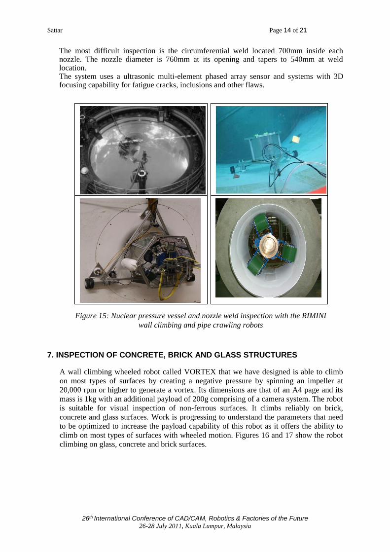
6. INSPECTION OF NUCLEAR PRESSURE VESSEL WELDS
Reactor Pressure Vessels are inspected with an outage on average every 1-5 years. The inspection must not interfere with other maintenance tasks. NDT is performed with Ultrasonic and eddy current techniques. Figure 15 shows the RIMINI wall climbing robot that is designed to inspect shell welds from inside a nuclear reactor pressure vessel (RPV) while submerged in water. It provides access to nozzles to enable another pipe crawling robot (carried by the climbing robot) to enter the nozzle pipe to inspect a circumferential weld located 700mm inside the nozzle. The robot is designed to withstand large doses of radiation. Two DC motors provide the drive actuation, 3 triangular suction cups provide adhesion to the RPV wall (3 air motors provide suction cup actuation). Welds in the RPV are classified as circumferential welds and nozzle welds. Circumferential welds are located at - flange to upper shell, upper shell to middle shell, middle shell to lower shell and lower shell to bottom head. Nozzle welds are located at - nozzle to middle shell, nozzle to nozzle pipe (so called safe end). Flange ligaments are also inspected. Some reactor vessels - vertical welds of reactor shell and safety injection nozzle welds are included in inspection Most RPV have at least six nozzles, the number of nozzle welds to be inspected is 12, and the number of circumferential weld inspections is sixteen. Thus many days are required to inspect one RPV.
Figure 13: Floating Production Storage of Oil (FPSO) requires NDT of welds on
strengthening plates located on the floor of a tank
Figure 14: The FPSO robot swims to a test location and descends (using active
buoyancy control) to the floor. It uses wheeled motion on the floor to move along
strengthening plates and perform weld inspection
Sattar Page 14 of 21
26th International Conference of CAD/CAM, Robotics & Factories of the Future 26-28 July 2011, Kuala Lumpur, Malaysia
The most difficult inspection is the circumferential weld located 700mm inside each nozzle. The nozzle diameter is 760mm at its opening and tapers to 540mm at weld location. The system uses a ultrasonic multi-element phased array sensor and systems with 3D focusing capability for fatigue cracks, inclusions and other flaws.
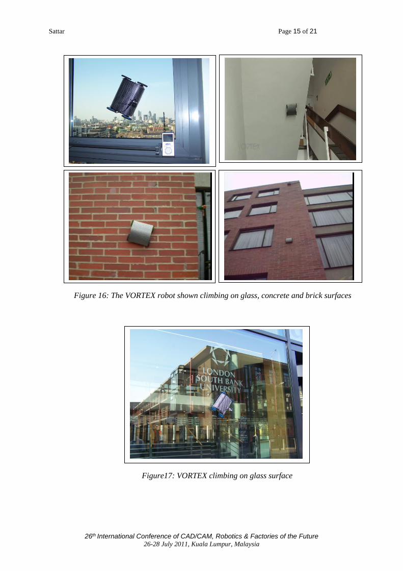
7. INSPECTION OF CONCRETE, BRICK AND GLASS STRUCTURES
A wall climbing wheeled robot called VORTEX that we have designed is able to climb
on most types of surfaces by creating a negative pressure by spinning an impeller at
20,000 rpm or higher to generate a vortex. Its dimensions are that of an A4 page and its
mass is 1kg with an additional payload of 200g comprising of a camera system. The robot
is suitable for visual inspection of non-ferrous surfaces. It climbs reliably on brick,
concrete and glass surfaces. Work is progressing to understand the parameters that need
to be optimized to increase the payload capability of this robot as it offers the ability to
climb on most types of surfaces with wheeled motion. Figures 16 and 17 show the robot
climbing on glass, concrete and brick surfaces.
Figure 15: Nuclear pressure vessel and nozzle weld inspection with the RIMINI
wall climbing and pipe crawling robots
Sattar Page 15 of 21
26th International Conference of CAD/CAM, Robotics & Factories of the Future 26-28 July 2011, Kuala Lumpur, Malaysia
Figure 16: The VORTEX robot shown climbing on glass, concrete and brick surfaces
Figure17: VORTEX climbing on glass surface

Sattar Page 16 of 21
26th International Conference of CAD/CAM, Robotics & Factories of the Future 26-28 July 2011, Kuala Lumpur, Malaysia
8. INSPECTION OF WIND TURBINE TOWERS AND BLADES
There is currently great interest in finding solutions to the in-situ inspection of wind blades. Wind turbine farms for sustainable electric power production are being planned worldwide. The largest wind turbines planned for the future will generate 5MW and involve fibre reinforced composite (FRP) blades up to 100m in length. Wind blades are subject to enormous stresses, especially in storm conditions in offshore locations. At the same time the use of FRP in safety critical structures located in such extreme environments is relatively new and it is likely that structural defects of a previously unknown nature may arise. Effective regular inspection for structural integrity inspection is thus essential. Access to offshore wind turbine blades poses tremendous problems, danger to human operatives and costs in the event of blades having to be taken out of service and transported to shore for scheduled inspections.
Robotic in-situ blade inspection of offshore wind turbines is a promising solution. A climbing robot carrying a micro focus X ray source and digital detector could deploy radiography to test a blade. Computed axial X ray tomography has been identified as the optimal if not the only solution for identification of safety critical defects in the thickest blade sections. The weight of such an inspection system is very high, typically 200kg and typical cross sectional scanner dimensions of 1m x 2 m to encircle as blade, clearly involve very high destabilizing moments to be countered by the deployment robot. Our solution [15] is a climbing ring robot completely encircling a turbine tower (typically 3 meter in diameter). Because of the size and thus development costs of such a huge robot, we have designed and prototyped a small scale model. The key design innovation is that the adhesive forces between the robot and climbing surface are provided entirely by mechanical means rather than by using the usual methods of vacuum suction or magnetic force. Figure 18 shows the CONCEPT ‘ring’ climbing robot, funded by the European Commission [16]developed from several modular frames that decrease in diameter from 4.5 m to 3 m at the top of the tower. The system has a Cartesian scanning arm to scan the blades from the top of the tower to the bottom. The blade can usually be rotated to change its “pitch”. This ability is useful to turn the blade in the radiation beam to enable 3D computation of a defect. The robot is then moved to a new position to obtain new results along the blade. The prototype has three modules which are completely identical and can be easily joined together to climb on any circumferential tube. The tower has a tapering radius. The robot is placed around the tower and it uses spring forces to grip it. Active force control could also be used to adapt to changing radius but this method has not been used here.
Figure 18: RING robot climbs on pipes and towers
Sattar Page 17 of 21
26th International Conference of CAD/CAM, Robotics & Factories of the Future 26-28 July 2011, Kuala Lumpur, Malaysia
Each module uses two motors, one for the drive motion and the other to turn the angle of the wheel so that the robot climbing trajectory is spiral. The robot has the capability to face the driver wheels in different angles which means that the robot can either climb along the tube, or with a certain pitch angle it can spiral around the tube, or if the wheel is turned through 90 degrees then the robot will not climb but it will rotate around the tube in the same spot. The prototype has been built to a linear scale of 1:10 (for both the robot and test pipe) and tested successfully performing the three types of motion i.e. up/down, spiral, and rotation on the spot. The robot weight is 3kg, the payload capacity is 2kg with a safety factor of 2 and maximum speeds of climbing and circumferential motions are 10m/min. In the full scale model the cross sectional area over which adhesive forces between the wheels and turbine tower could be developed would increase by a factor of 100 (assuming the wheel widths and diameters to be scaled up by a factor of 10 and the payload capacity can thus be potentially increased in the same proportion to about 200kg, the target figure. However, if necessary, adhesion forces can always be augmented in the full scale design by the inclusion of a number of rare earth magnet arrays.
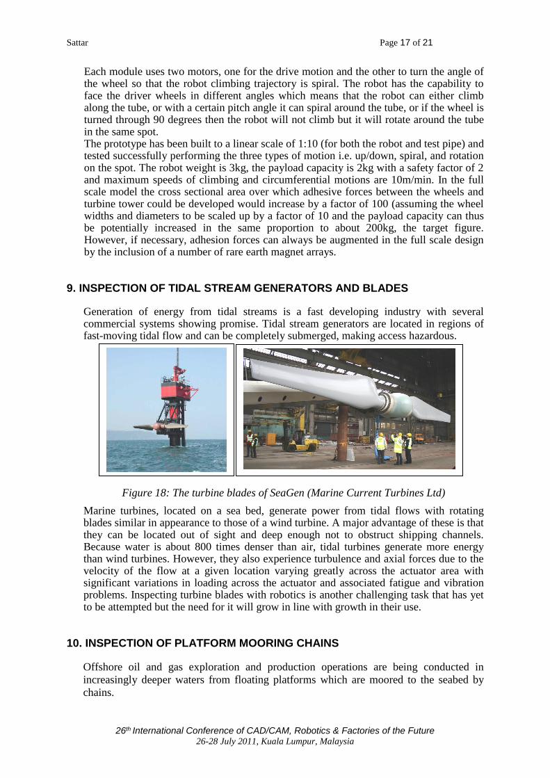
9. INSPECTION OF TIDAL STREAM GENERATORS AND BLADES
Generation of energy from tidal streams is a fast developing industry with several commercial systems showing promise. Tidal stream generators are located in regions of fast-moving tidal flow and can be completely submerged, making access hazardous.
Marine turbines, located on a sea bed, generate power from tidal flows with rotating blades similar in appearance to those of a wind turbine. A major advantage of these is that they can be located out of sight and deep enough not to obstruct shipping channels. Because water is about 800 times denser than air, tidal turbines generate more energy than wind turbines. However, they also experience turbulence and axial forces due to the velocity of the flow at a given location varying greatly across the actuator area with significant variations in loading across the actuator and associated fatigue and vibration problems. Inspecting turbine blades with robotics is another challenging task that has yet to be attempted but the need for it will grow in line with growth in their use.
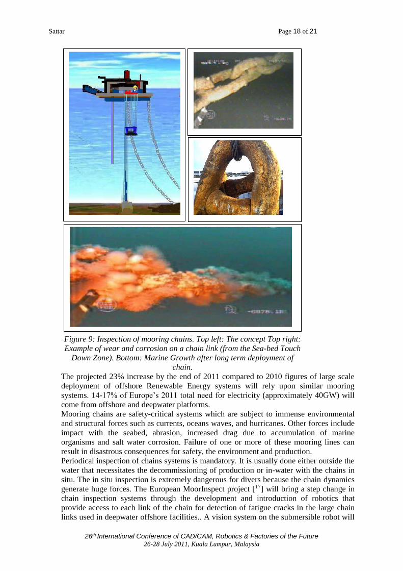
10. INSPECTION OF PLATFORM MOORING CHAINS
Offshore oil and gas exploration and production operations are being conducted in
increasingly deeper waters from floating platforms which are moored to the seabed by
chains.
Figure 18: The turbine blades of SeaGen (Marine Current Turbines Ltd)
Sattar Page 18 of 21
26th International Conference of CAD/CAM, Robotics & Factories of the Future 26-28 July 2011, Kuala Lumpur, Malaysia
The projected 23% increase by the end of 2011 compared to 2010 figures of large scale
deployment of offshore Renewable Energy systems will rely upon similar mooring
systems. 14-17% of Europe’s 2011 total need for electricity (approximately 40GW) will
come from offshore and deepwater platforms.
Mooring chains are safety-critical systems which are subject to immense environmental
and structural forces such as currents, oceans waves, and hurricanes. Other forces include
impact with the seabed, abrasion, increased drag due to accumulation of marine
organisms and salt water corrosion. Failure of one or more of these mooring lines can
result in disastrous consequences for safety, the environment and production.
Periodical inspection of chains systems is mandatory. It is usually done either outside the
water that necessitates the decommissioning of production or in-water with the chains in
situ. The in situ inspection is extremely dangerous for divers because the chain dynamics
generate huge forces. The European MoorInspect project [17] will bring a step change in
chain inspection systems through the development and introduction of robotics that
provide access to each link of the chain for detection of fatigue cracks in the large chain
links used in deepwater offshore facilities.. A vision system on the submersible robot will
Figure 9: Inspection of mooring chains. Top left: The concept Top right:
Example of wear and corrosion on a chain link (from the Sea-bed Touch
Down Zone). Bottom: Marine Growth after long term deployment of
chain.
Sattar Page 19 of 21
26th International Conference of CAD/CAM, Robotics & Factories of the Future 26-28 July 2011, Kuala Lumpur, Malaysia
give early indication of problems. The robot will clean a link before strapping a Medium
Range Ultrasonic Transducer collar to a cleaned area. Each link will be tested with
medium range ultrasound guided waves.
11. CONCLUSION
The mobile robots presented here are designed to provide access to inspection sites on very large structures and/or test sites located in hazardous environments. The robots deploy sensors to implement an appropriate technique from the full range of NDT techniques to find defects such as cracks, inclusions, lamination debonding and the extent of corrosion on steel structures. Robotic access both speeds up the inspection and reduces costs by eliminating the expensive and lengthy erection of scaffolding or the preparation of the site before humans can manually perform the inspection. Thus outage turnaround can be reduced or an outage prevented where the robotic inspection can be performed while the plant is in service. Robotic deployment of NDT is the only means of performing testing where the test site is located in hazardous and dangerous environments.
12. RECOMMENDATIONS
There are numerous industrial inspection tasks requiring these types of inspection robots.
Recent developments in cheap wireless control, mobile communications, improved
battery technology and spatial positioning systems now offers the means to build small
umbilical-free mobile robots that can be deployed cheaply and quickly to go to a remote
test site, gather NDT data, stamp its position and have it analyzed in real-time by an
operator sitting safely some distance away.
Further research and development is required to develop robots to go inside petro-
chemical storage tanks (while full of product) to inspect floors for pitting and corrosion,
to climb on the hulls of steel ships to inspect hundreds of kilometres of weld, to inspect
the walls of petro-chemical storage tanks for corrosion and weld integrity, to inspect
nozzle welds inside nuclear pressure vessels, to inspect structures such as dams and
bridges for cracks, to inspect overhead power cables, to internally inspect buried pipelines
that are currently not reachable by intelligent pigs, to climb up off-shore wind turbine
towers to inspect the blades, and to climb on aircraft wings and fuselage to detect for
cracks and loose rivets.
ACKNOWLEDGEMENTS
The support of the European Commission under projects Moorinspect FP7-SME-2011-1,
286976, COOP-CT-2006-032949, and NMP2-CT-2005-017509 is gratefully
acknowledged, and Nueva Granada Military University of Colombia for sponsoring Dr
Leon Rodriguez.

Sattar Page 20 of 21
26th International Conference of CAD/CAM, Robotics & Factories of the Future 26-28 July 2011, Kuala Lumpur, Malaysia
REFERENCES
[1] Topics On Nondestructive Evaluation (TONE), Volume 4, Automation, Miniature
Robotics and Sensors for Nondestructive Evaluation and Testing, Technical Editor: Yoseph
Bar-Cohen, ASNT, ISBN:1-57117-043-X
[2] Special issue on NDT Robots, In Industrial Robot: An International Journal, Vol.37 , No.
5, 2010, Emerald Group Publishing Limited, ISSN 0143-991X
[3] Sattar, T., Robotic Non Destructive Testing, Viewpoint: Robotic non destructive testing,
Special issue on NDT Robots, In Industrial Robot: An International Journal, Vol.37 , No. 5,
2010, Emerald Group Publishing Limited, ISSN 0143-991X
[4] Bridge B, Sattar T., Chen S, Khalid A , On the design of multi-task, compact, climbing
robotic NDT systems for remote operation on large surfaces and in hazardous environments,
Nondestructive Testing and Evaluation, 1997, Vol 3, pp 85-111.
[5] Chen S., Sattar T.P., Khalid A., Bridge B. (1996) Design, development and performance
Evaluation of a new pneumatically powered versatile wall climbing robotic NDT system
suitable for hazardous environments, Proceedings of the 14th World Conference on NDT
(14th WCNDT), Vol. 1-5, Ch. 566, pp 1023-1026.
[6] European FP6 STREP programme CROCELLS Contract No. NMP2-CT-2005-017509,
Climbing Robot Cell for Fast and Flexible Manufacture of large Scale Structures
[7] Shang, J., Bridge, B., Sattar, T.P., Mondal, S., Brenner, A., Development of a climbing
robot for the NDT of long weld lines, Industrial Robot: An international Journal, Volume 35
Issue 3, 2008, Emerald Group Publishing Ltd., ISSN 0143-991X
[8] Mondal, S.C., Bryan, B., Sattar T. P., Patel, T., Remote mobile vehicle and its suitable
non destructive testing (NDT) inspection methods for the melt weld inspection, Proceedings
of 13th International Conference On Climbing and Walking Robots and the Support
Technologies for Mobile Machines, 2010 [9] Shang, J.; Sattar, T.; Chen S.; Bridge, B. Design of a Climnbing Robot for Inspecting Aircraft Wings and Fuselage, Industrial Robot: An International Journal, Vol. 34, No. 6, 2007, Emeral Group Publishing Limited, ISSN 0143-991X
[10] Sattar, T.P., Leon-Rodriguez, H.E., Shang, J., Amphibious NDT Robots, Chapter 6
Climbing and Walking Robots, Towards New Applications, International Journal of
Advanced Robotics Systems, 2006, ISBN 978-3-902613-16-5, 24 pages
[11] Berger,A., Knape, B.,Thompson, B., Development of a Remote Tank Inspection (RTI)
Robotic System, Proceedings of 1990 American Nuclear Society Winter
Meeting,Washington D.C., November 1990
[12] Schempf H. (1994). Neptune-Above-Ground Storage Inspection Robot System,
Proceeding of IEEE International Conference on Robotics and Automation, San Diego, Vols
1-4, Part 2. pg. 1403-1408
[13] Maverick Demonstration “Submarine that goes in Gasoline”, Solex Robotics,
http://www.solexrobotics.com/Solex6.html
[14] Sattar, T.P., Leon-Rodriguez, H.E., Shang, J., Amphibious NDT Robots, Chapter 6
Climbing and Walking Robots, Towards New Applications, International Journal of
Advanced Robotics Systems, ISBN 978-3-902613-16-5, 24 pages, 2007
[15] Sattar, T.P., Leon Rodriguez, H.E. and Bridge, B. Climbing Ring Robot for inspection
of off-shore wind turbines, Industrial Robot: The international journal of industrial and
service robotics, Number 4 Mobile robots + CLAWAR, Vol. 36 No. 4, 2009, pp326-
330Emerald Group Publishing Limited, ISSN 0143-991X

Sattar Page 21 of 21
26th International Conference of CAD/CAM, Robotics & Factories of the Future 26-28 July 2011, Kuala Lumpur, Malaysia
[16] European CRAFT project CONCEPT-INSPECT, “Computerised Open Environment
Portable Tomography”, 6th Framework Programme CRAFT COOP-SME: COOP-CT-2006-
032949.
[17] MoorInspect: Development of an advanced medium range ultrasonic technique for
mooring chains inspection in water, European FP7 Collaborative projects, Networks of
Excellence, Coordination and Support Actions, research for the benefits of specific groups (In
particular SMES), Grant agreement no.: 286976