roche avl9120 9130_9140_9180_9181_-_service_manual
TRANSCRIPT
MED
ICA
L IN
STR
UM
ENTS
AVL 9120, 9130,9140, 9180, 9181
Electrolyte Analyzers
Service Manual
Tenth EditionNovember 1997
Copyright, 1997, AVL Scientific Corporation. All rights reserved. Unless otherwise noted, no part of thispublication may be reproduced, transmitted, transcribed, stored in a retrieval system, or translated intoany language in any form without the written permission of AVL Scientific Corporation.
For information contact:
AVL Scientific Corporation AVL MEDICAL INSTRUMENTS AG AVL LIST GmbH50 Mansell Court Stettemerstrasse 28 Kleiststrasse 48P.O. Box 337 CH-8207 Schaffhausen A-8020 GrazRoswell, Georgia USA 30077 Switzerland Austria1-800-526-2272 41-848-800-885 43-316-787-0
Printed in USA
US0285 REV K
ii
This Operator´s Manual contains important warnings and safety information to be observed by theuser.
This instrument is only intended for one area of application which is described in the instruc-tions. The most important prerequisites for application, operation and safety, are explained toensure smooth operation. No warranty or liability claims will be covered if the instrument isapplied in areas other than those described or if the necessary prerequisites and safetymeasures are not observed.
The instrument is only to be operated by qualified personnel capable of observing theseprerequisites.
Only accessories and supplies either delivered by or approved by AVL are to be used with theinstrument.
Due to the operating principle of the instrument, analytical accuracy not only depends oncorrect operation and function, but also upon a variety of external influences beyond themanufacturers control. Therefore, the test results from this instrument must be carefullyexamined by an expert, before further measures are taken based on the analytical results.
Instrument adjustment and maintenance with removed covers and connected power mains areonly to be performed by a qualified technician who is aware of the dangers involved.
Instrument repairs are only to be performed by the manufacturer or qualified service personnel.
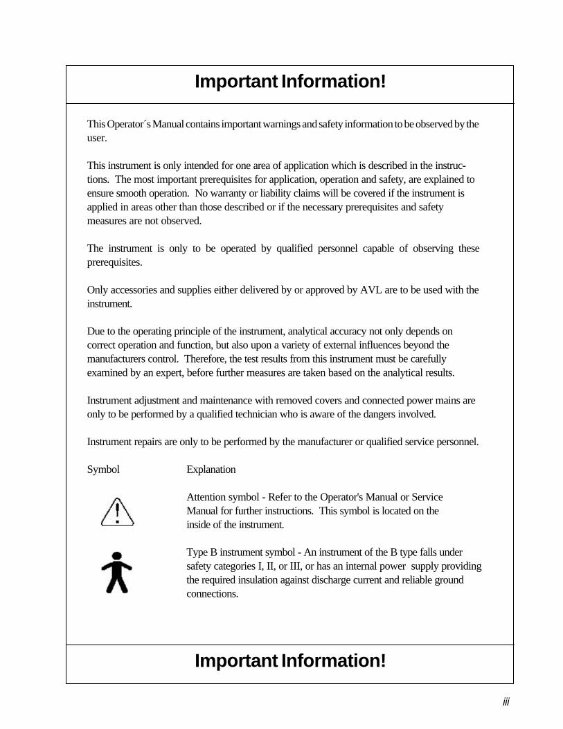
Symbol Explanation
Attention symbol - Refer to the Operator's Manual or ServiceManual for further instructions. This symbol is located on theinside of the instrument.
Type B instrument symbol - An instrument of the B type falls undersafety categories I, II, or III, or has an internal power supply providingthe required insulation against discharge current and reliable groundconnections.
Important Information!
iii
Important Information!
• This instrument falls under Safety Category I.• This instrument is a Class B instrument.
This device complies with Part 15 of the FCC Rules. Operation is subject to the following twoconditions: (1) this device may not cause harmful interference’s, and (2) this device must acceptany interference received, including interference that may cause undesired operation.
Warning: Changes or modifications to this unit not expressly approved by the partyresponsible for compliance could void the user’s authority to operate the equipment.
Note: This equipment has been tested and found to comply with the limits for a Class Bdigital device, pursuant to Part 15 of the FCC Rules. These limits are designed to providereasonable protection against harmful interference in a residential installation.This equipment generates, uses, and can radiate radio frequency energy and, if notinstalled and used in accordance with the instructions, may cause harmful interference toradio communication. However, there is no guarantee that interference will not occur in aparticular installation. If this equipment does not cause harmful interference to radio ortelevision reception, which can be determined by turning the equipment off and on, theuser is encouraged to try to correct the interference by one or more of the followingmeasures:
• Reorient or relocate the receiving antenna• Increase the separation between the equipment and receiver• Connect the equipment into an outlet on a circuit different from that to which
the receiver is connected.• Consult the dealer or an experienced radio TV technician for help
Caution:• The instrument is designed as a conventional device (closed, not waterproof type).• Do not operate the instrument in an explosive environment or in the vicinity of
explosive anesthetic mixtures containing oxygen or nitrous oxide.• This instrument is suitable for continuous operation.• The power plug is to be plugged into a ground socket only. When using an extension
cord, make sure that it is of the proper size and is properly grounded.• Any breakage of the ground lead inside or outside the instrument or a loose ground
connection can cause a hazardous condition when operating the instrument.Intentional disconnection of the grounding is not permitted.
• When replacing the fuses, make sure that they are of the same type and rating as theoriginal fuses. Never use repaired fuses or short-circuit the fuse holders.
Operating Safety Information
iv
Operating Safety Information
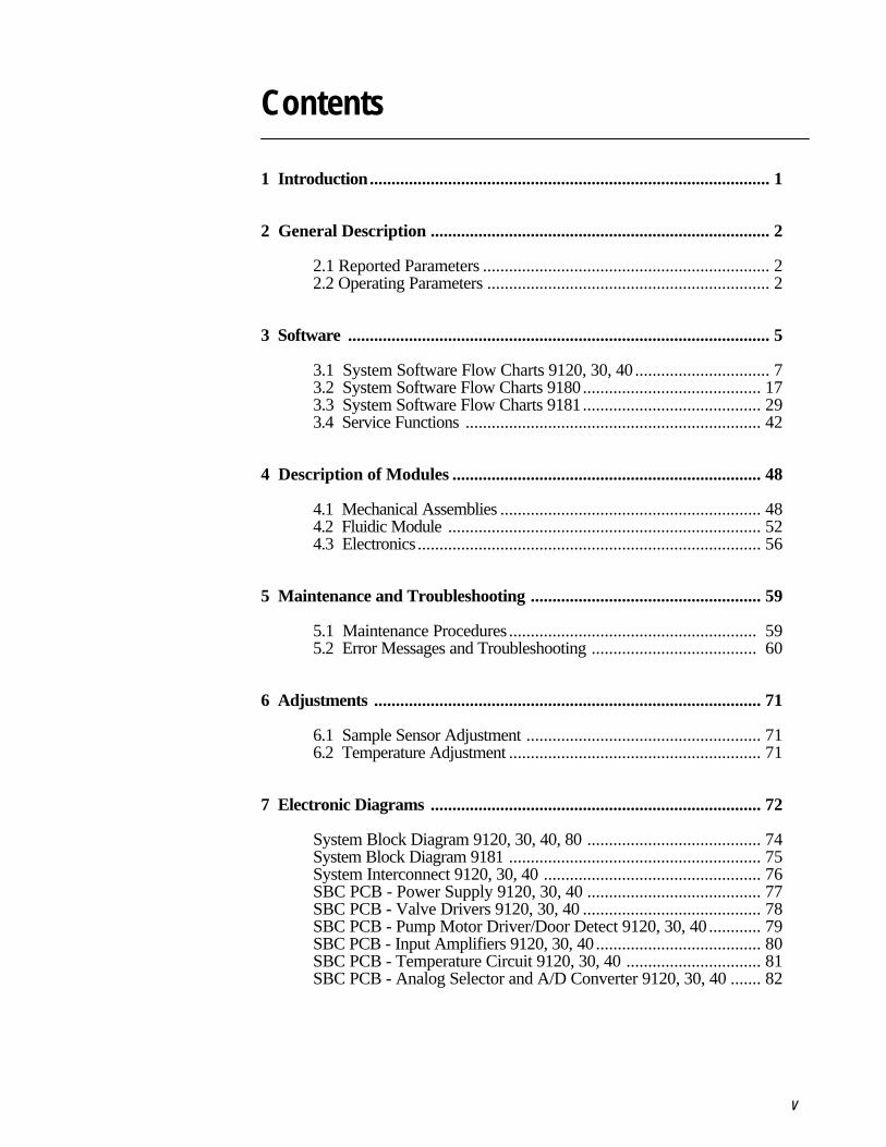
Contents
1 Introduction............................................................................................ 1
2 General Description .............................................................................. 2
2.1 Reported Parameters .................................................................. 22.2 Operating Parameters ................................................................. 2
3 Software ................................................................................................. 5
3.1 System Software Flow Charts 9120, 30, 40 ............................... 73.2 System Software Flow Charts 9180......................................... 173.3 System Software Flow Charts 9181......................................... 293.4 Service Functions .................................................................... 42
4 Description of Modules ....................................................................... 48
4.1 Mechanical Assemblies ............................................................ 484.2 Fluidic Module ........................................................................ 524.3 Electronics ............................................................................... 56
5 Maintenance and Troubleshooting ..................................................... 59
5.1 Maintenance Procedures ......................................................... 595.2 Error Messages and Troubleshooting ...................................... 60
6 Adjustments ......................................................................................... 71
6.1 Sample Sensor Adjustment ...................................................... 716.2 Temperature Adjustment .......................................................... 71
7 Electronic Diagrams ............................................................................ 72
System Block Diagram 9120, 30, 40, 80 ........................................ 74System Block Diagram 9181 .......................................................... 75System Interconnect 9120, 30, 40 .................................................. 76SBC PCB - Power Supply 9120, 30, 40 ........................................ 77SBC PCB - Valve Drivers 9120, 30, 40 ......................................... 78SBC PCB - Pump Motor Driver/Door Detect 9120, 30, 40 ............ 79SBC PCB - Input Amplifiers 9120, 30, 40...................................... 80SBC PCB - Temperature Circuit 9120, 30, 40 ............................... 81SBC PCB - Analog Selector and A/D Converter 9120, 30, 40 ....... 82
v
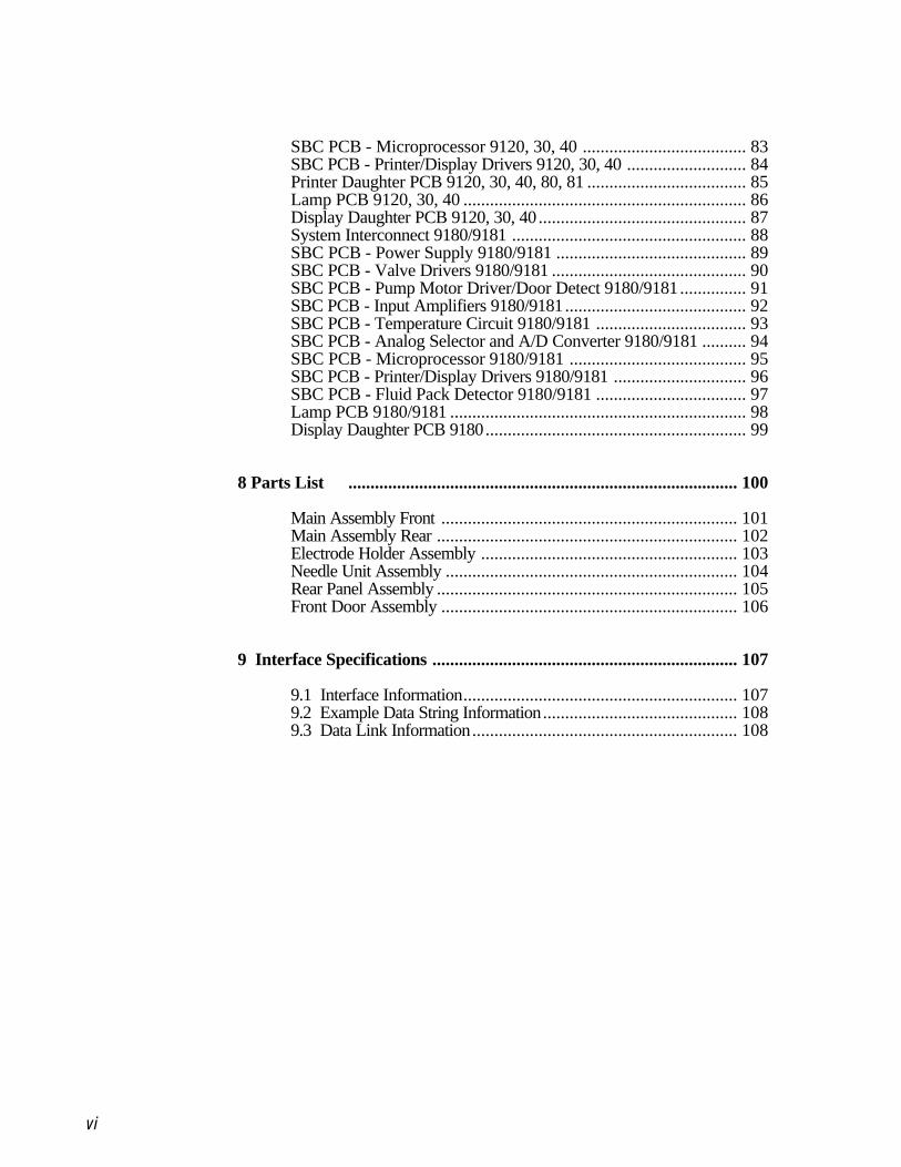
SBC PCB - Microprocessor 9120, 30, 40 ..................................... 83SBC PCB - Printer/Display Drivers 9120, 30, 40 ........................... 84Printer Daughter PCB 9120, 30, 40, 80, 81 .................................... 85Lamp PCB 9120, 30, 40 ................................................................ 86Display Daughter PCB 9120, 30, 40............................................... 87System Interconnect 9180/9181 ..................................................... 88SBC PCB - Power Supply 9180/9181 ........................................... 89SBC PCB - Valve Drivers 9180/9181 ............................................ 90SBC PCB - Pump Motor Driver/Door Detect 9180/9181............... 91SBC PCB - Input Amplifiers 9180/9181......................................... 92SBC PCB - Temperature Circuit 9180/9181 .................................. 93SBC PCB - Analog Selector and A/D Converter 9180/9181 .......... 94SBC PCB - Microprocessor 9180/9181 ........................................ 95SBC PCB - Printer/Display Drivers 9180/9181 .............................. 96SBC PCB - Fluid Pack Detector 9180/9181 .................................. 97Lamp PCB 9180/9181 ................................................................... 98Display Daughter PCB 9180........................................................... 99
8 Parts List ........................................................................................ 100
Main Assembly Front ................................................................... 101Main Assembly Rear .................................................................... 102Electrode Holder Assembly .......................................................... 103Needle Unit Assembly .................................................................. 104Rear Panel Assembly .................................................................... 105Front Door Assembly ................................................................... 106
9 Interface Specifications ..................................................................... 107
9.1 Interface Information.............................................................. 1079.2 Example Data String Information............................................ 1089.3 Data Link Information............................................................ 108
vi
1 Introduction
The Service Manual for the 9120, 30, 40, 80, and 81 Electrolyte Analyzerscontains the technical information needed to ensure easy fault identification.This manual is intended to be complementary to the Operator's Manual wheredetailed instructions for operation, maintenance and troubleshooting areprovided.
As for all clinical instrumentation, a thorough understanding of the principlesof operation is prerequisite to attempting service of this product. Trainingalong with experience will enhance the use of this manual.
Service and repair of 9120, 30, 40, 80, and 81 analyzers should be performedonly by qualified repair technicians. Care should be taken when removing thecovers as hazardous voltages are exposed. Use only accepted electronic testprocedures and static protection when replacing and handling all electronicparts.
This manual is divided into 9 chapters to facilitate location of technical infor-mation. Chapter 2 provides specifications and operating parameter informa-tion. Chapter 3 includes flow charts for all system functions and detailedoperation of system test procedures. In Chapter 4, all mechanical, fluidic andelectronic assemblies are described. Chapter 5 outlines routine maintenanceand troubleshooting procedures. Chapter 6 includes electronic adjustmentsand Chapter 7 provides the system block diagram and all circuit schematicdiagrams and wiring interconnection information. In Chapter 8, part identifica-tion, location and description is provided by the illustrated parts list.Finally, in Chapter 9 interface specifications are provided for the RS232output.
1
2
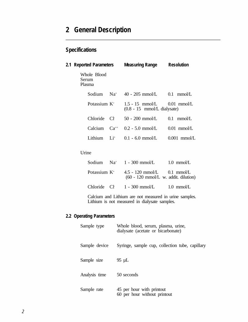
2 General Description
Specifications
2.1 Reported Parameters Measuring Range Resolution
Whole BloodSerumPlasma
Sodium Na+ 40 - 205 mmol/L 0.1 mmol/L
Potassium K+ 1.5 - 15 mmol/L 0.01 mmol/L(0.8 - 15 mmol/L dialysate)
Chloride Cl- 50 - 200 mmol/L 0.1 mmol/L
Calcium Ca++ 0.2 - 5.0 mmol/L 0.01 mmol/L
Lithium Li+ 0.1 - 6.0 mmol/L 0.001 mmol/L
Urine
Sodium Na+ 1 - 300 mmol/L 1.0 mmol/L
Potassium K+ 4.5 - 120 mmol/L 0.1 mmol/L (60 - 120 mmol/L w. addit. dilution)
Chloride Cl- 1 - 300 mmol/L 1.0 mmol/L
Calcium and Lithium are not measured in urine samples.Lithium is not measured in dialysate samples.
2.2 Operating Parameters
Sample type Whole blood, serum, plasma, urine,dialysate (acetate or bicarbonate)
Sample device Syringe, sample cup, collection tube, capillary
Sample size 95 µL
Analysis time 50 seconds
Sample rate 45 per hour with printout60 per hour without printout
3
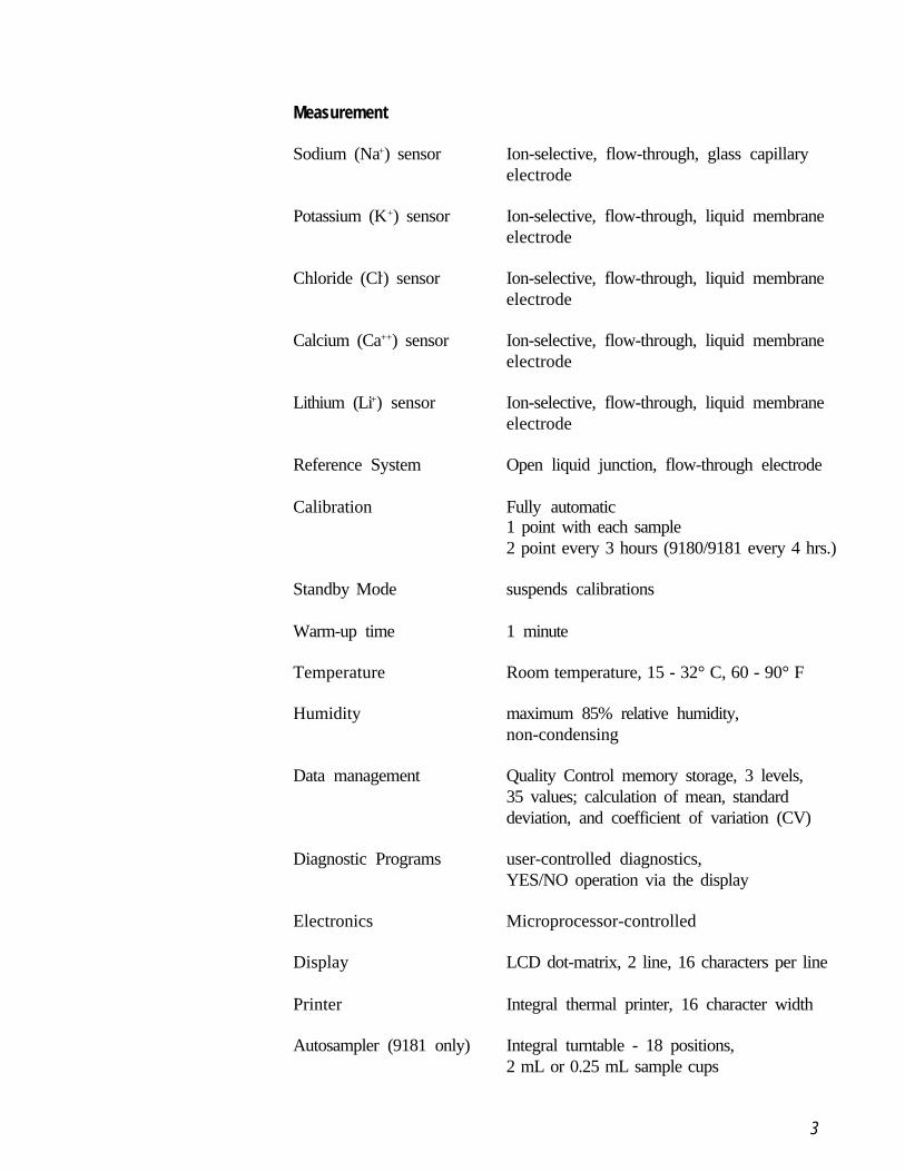
Measurement
Sodium (Na+) sensor Ion-selective, flow-through, glass capillaryelectrode
Potassium (K+) sensor Ion-selective, flow-through, liquid membraneelectrode
Chloride (Cl-) sensor Ion-selective, flow-through, liquid membraneelectrode
Calcium (Ca++) sensor Ion-selective, flow-through, liquid membraneelectrode
Lithium (Li+) sensor Ion-selective, flow-through, liquid membraneelectrode
Reference System Open liquid junction, flow-through electrode
Calibration Fully automatic1 point with each sample2 point every 3 hours (9180/9181 every 4 hrs.)
Standby Mode suspends calibrations
Warm-up time 1 minute
Temperature Room temperature, 15 - 32° C, 60 - 90° F
Humidity maximum 85% relative humidity,non-condensing
Data management Quality Control memory storage, 3 levels,35 values; calculation of mean, standarddeviation, and coefficient of variation (CV)
Diagnostic Programs user-controlled diagnostics,YES/NO operation via the display
Electronics Microprocessor-controlled
Display LCD dot-matrix, 2 line, 16 characters per line
Printer Integral thermal printer, 16 character width
Autosampler (9181 only) Integral turntable - 18 positions,2 mL or 0.25 mL sample cups
4
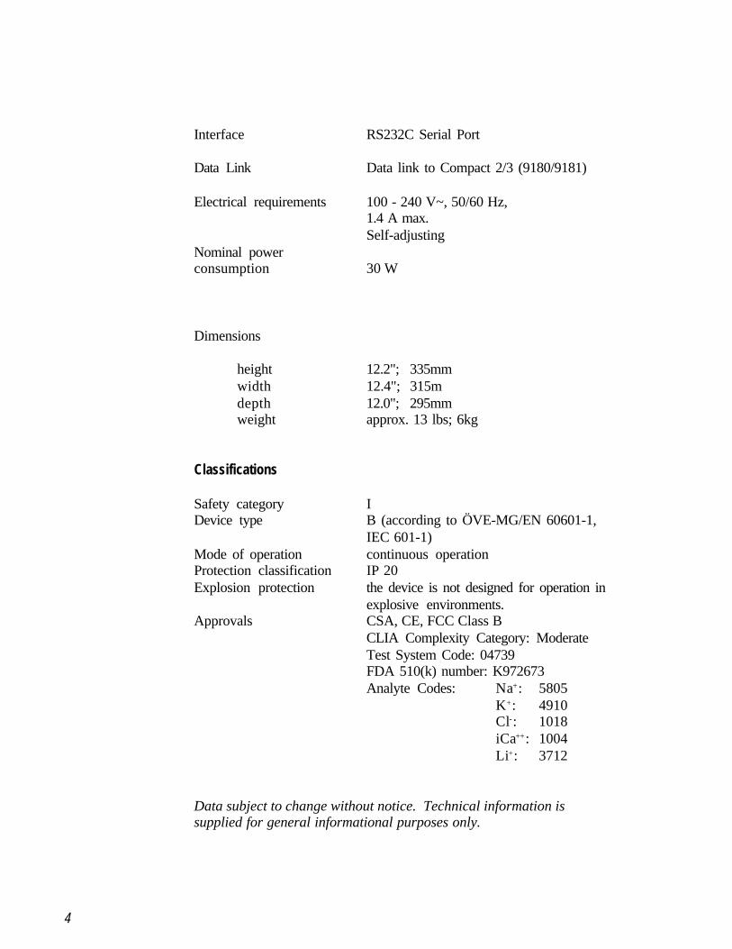
Interface RS232C Serial Port
Data Link Data link to Compact 2/3 (9180/9181)
Electrical requirements 100 - 240 V~, 50/60 Hz,1.4 A max.Self-adjusting
Nominal powerconsumption 30 W
Dimensions
height 12.2"; 335mmwidth 12.4"; 315mdepth 12.0"; 295mmweight approx. 13 lbs; 6kg
Classifications
Safety category IDevice type B (according to ÖVE-MG/EN 60601-1,
IEC 601-1)Mode of operation continuous operationProtection classification IP 20Explosion protection the device is not designed for operation in
explosive environments.Approvals CSA, CE, FCC Class B
CLIA Complexity Category: ModerateTest System Code: 04739FDA 510(k) number: K972673Analyte Codes: Na+: 5805
K+: 4910Cl-: 1018iCa++: 1004Li+: 3712
Data subject to change without notice. Technical information issupplied for general informational purposes only.
5
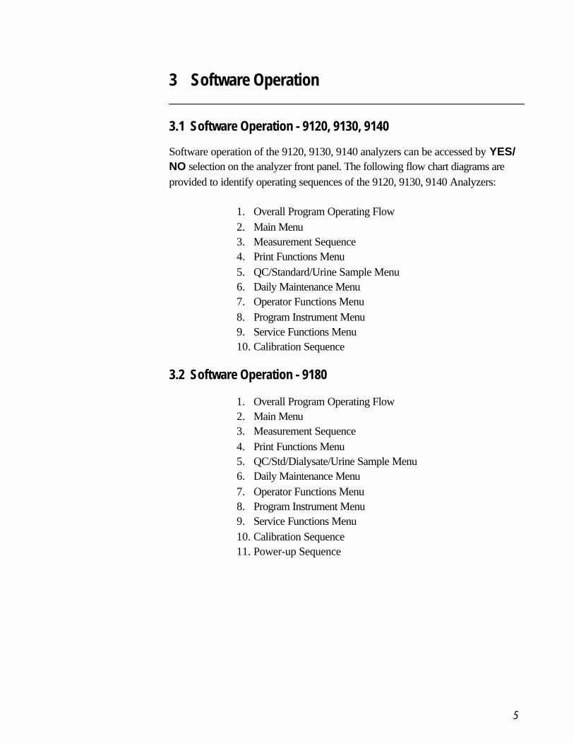
3 Software Operation
3.1 Software Operation - 9120, 9130, 9140
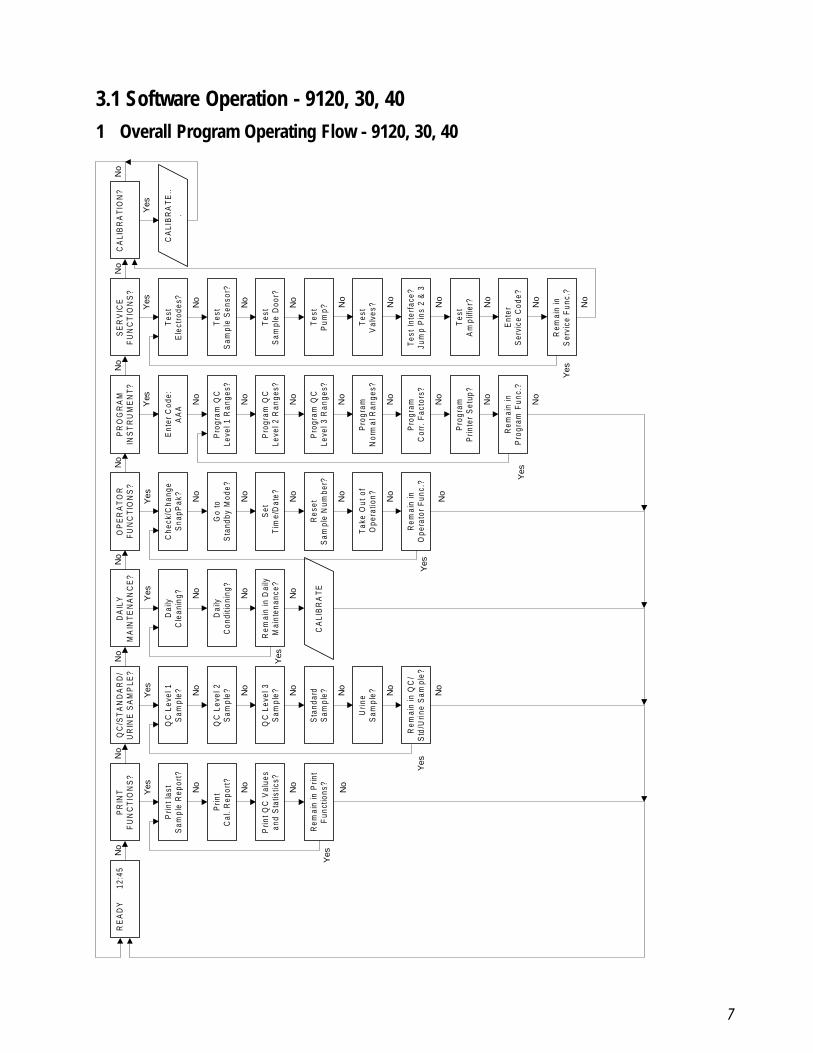
Software operation of the 9120, 9130, 9140 analyzers can be accessed by YES/NO selection on the analyzer front panel. The following flow chart diagrams areprovided to identify operating sequences of the 9120, 9130, 9140 Analyzers:
1. Overall Program Operating Flow2. Main Menu3. Measurement Sequence4. Print Functions Menu5. QC/Standard/Urine Sample Menu6. Daily Maintenance Menu7. Operator Functions Menu8. Program Instrument Menu9. Service Functions Menu10. Calibration Sequence
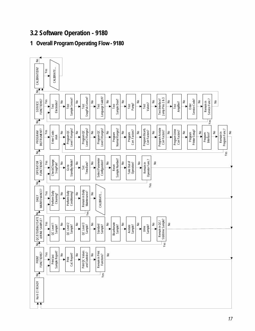
3.2 Software Operation - 9180
1. Overall Program Operating Flow2. Main Menu3. Measurement Sequence4. Print Functions Menu5. QC/Std/Dialysate/Urine Sample Menu6. Daily Maintenance Menu7. Operator Functions Menu8. Program Instrument Menu9. Service Functions Menu10. Calibration Sequence11. Power-up Sequence
6
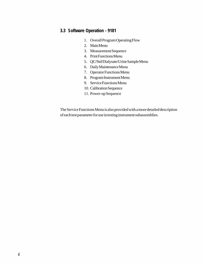
3.3 Software Operation - 9181
1. Overall Program Operating Flow2. Main Menu3. Measurement Sequence4. Print Functions Menu5. QC/Std/Dialysate/Urine Sample Menu6. Daily Maintenance Menu7. Operator Functions Menu8. Program Instrument Menu9. Service Functions Menu10. Calibration Sequence11. Power-up Sequence
The Service Functions Menu is also provided with a more detailed descriptionof each test parameter for use in testing instrument subassemblies.
7
3.1 Software Operation - 9120, 30, 401 Overall Program Operating Flow - 9120, 30, 40
No
No
No
No
No
No
No
No
Yes
RE
AD
Y
12:
45P
RIN
TF
UN
CT
ION
S?
QC
/ST
AN
DA
RD
/U
RIN
E S
AM
PLE
?D
AIL
YM
AIN
TE
NA
NC
E?
OP
ER
AT
OR
FU
NC
TIO
NS
?S
ER
VIC
EF
UN
CT
ION
S?
CA
LIB
RA
TIO
N?
Tes
tE
lect
rode
s?
Tes
tS
ampl
e S
enso
r?
Tes
tS
ampl
e D
oor?
Tes
tP
ump?
Tes
tV
alve
s?
Tes
t In
terf
ace?
Jum
p P
ins
2 &
3
Tes
tA
mpl
ifier
?
Ent
erS
ervi
ce C
ode?
Rem
ain
inS
ervi
ce F
unc.
?
Prin
t las
tS
ampl
e R
epor
t?
Prin
tC
al.
Rep
ort?
Prin
t QC
Val
ues
and
Sta
tistic
s?
Rem
ain
in P
rint
Fun
ctio
ns?
QC
Lev
el 1
Sam
ple?
QC
Lev
el 2
Sam
ple?
QC
Lev
el 3
Sam
ple?
Sta
ndar
dS
ampl
e?
Urin
eS
ampl
e?
Rem
ain
in Q
C/
Std
/Urin
e S
ampl
e?
Dai
lyC
lean
ing?
Dai
lyC
ondi
tioni
ng?
Rem
ain
in D
aily
Mai
nten
ance
?
CA
LIB
RA
TE
Che
ck/C
hang
eS
napP
ak?
Go
toS
tand
by M
ode?
Set
Tim
e/D
ate?
Res
etS
ampl
e N
umbe
r?
Tak
e O
ut o
fO
pera
tion?
Rem
ain
inO
pera
tor
Fun
c.?
PR
OG
RA
MIN
ST
RU
ME
NT
?
Ent
er C
ode:
AA
A
Pro
gram
QC
Leve
l 1 R
ange
s?
Pro
gram
QC
Leve
l 2 R
ange
s?
Pro
gram
QC
Leve
l 3 R
ange
s?
Pro
gram
Nor
mal
Ran
ges?
Pro
gram
Cor
r. F
acto
rs?
Pro
gram
Prin
ter
Set
up?
Rem
ain
inP
rogr
am F
unc.
?
CA
LIB
RA
TE
...
No
Yes No
No
No
No
No
No
No
No
No
No
No
No
No
No
No
No
No
No
No
No
No
No
No
No
No
No
No
No
No
No
No
No
No
Yes
Yes
Yes
Yes
Yes
Yes
Yes
No
Yes
Yes
No
Yes
Yes
8
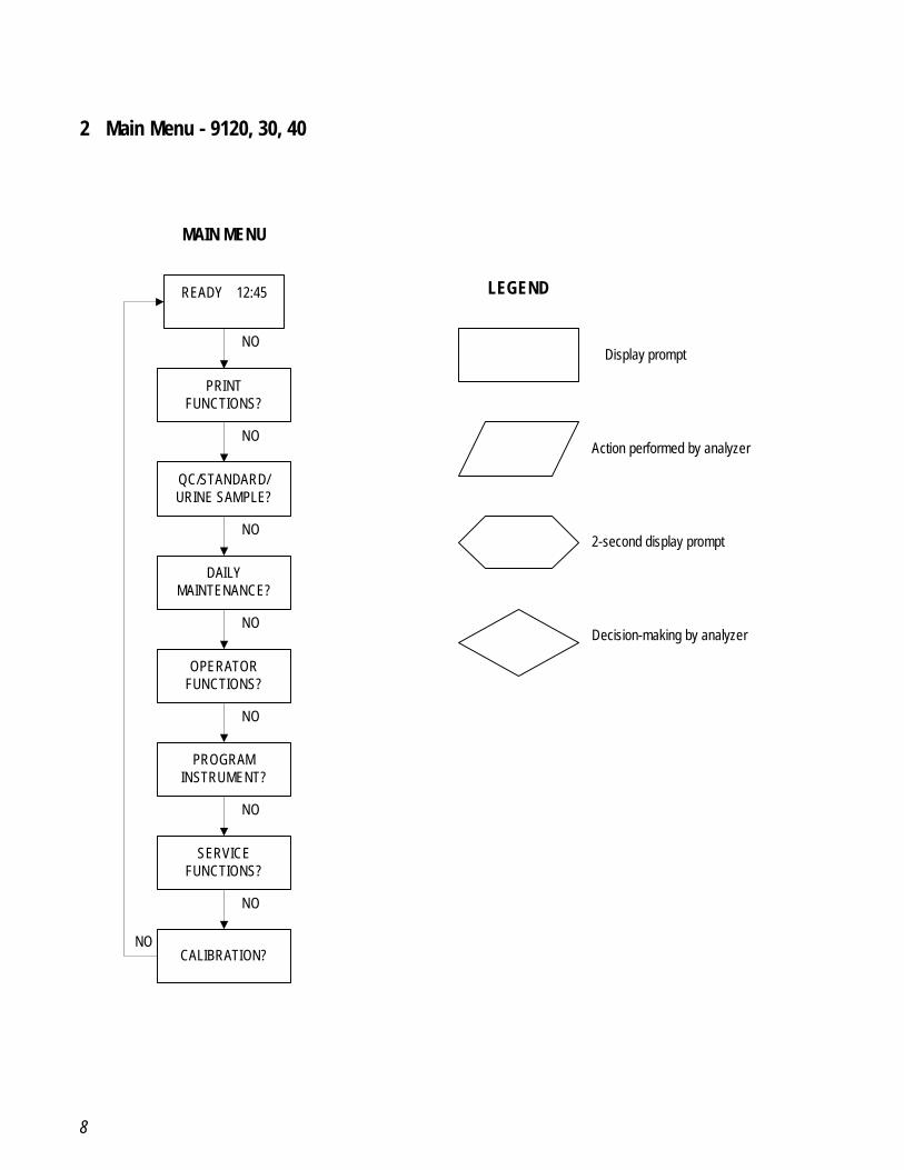
2 Main Menu - 9120, 30, 40
READY 12:45
PRINTFUNCTIONS?
QC/STANDARD/URINE SAMPLE?
DAILYMAINTENANCE?
OPERATORFUNCTIONS?
PROGRAMINSTRUMENT?
SERVICEFUNCTIONS?
CALIBRATION?
MAIN MENU
LEGEND
Display prompt
Action performed by analyzer
2-second display prompt
Decision-making by analyzer
NO
NO
NO
NO
NO
NO
NO
NO
9
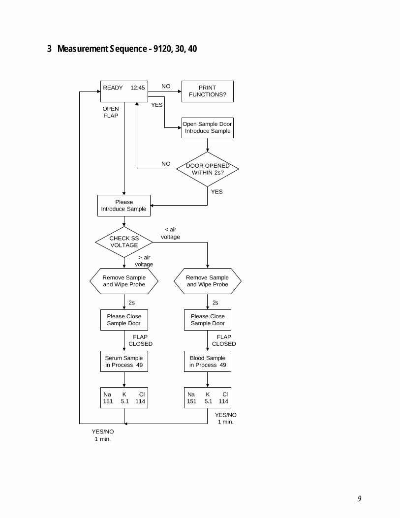
3 Measurement Sequence - 9120, 30, 40
READY 12:45
DOOR OPENEDWITHIN 2s?
Remove Sampleand Wipe Probe
PRINTFUNCTIONS?
Open Sample DoorIntroduce Sample
PleaseIntroduce Sample
CHECK SSVOLTAGE
Remove Sampleand Wipe Probe
Please CloseSample Door
Please CloseSample Door
Serum Samplein Process 49
Blood Samplein Process 49
Na K Cl151 5.1 114
Na K Cl151 5.1 114
NO
YESOPENFLAP
NO
YES
< airvoltage
> airvoltage
2s 2s
FLAPCLOSED
FLAPCLOSED
YES/NO1 min.
YES/NO1 min.
10
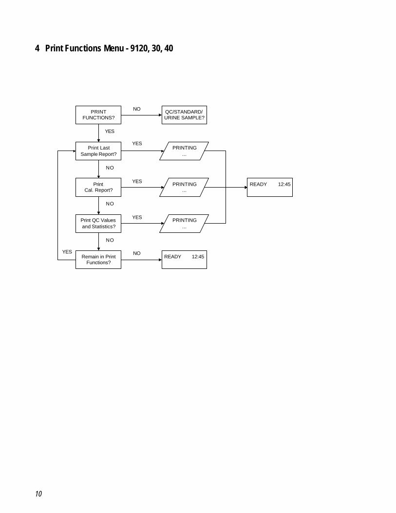
4 Print Functions Menu - 9120, 30, 40
PRINTFUNCTIONS?
PRINTING...
QC/STANDARD/URINE SAMPLE?
Print LastSample Report?
PrintCal. Report?
Print QC Valuesand Statistics?
Remain in PrintFunctions?
READY 12:45
READY 12:45PRINTING...
PRINTING...
NO
NO
NO
NO
NO
YES
YES
YES
YES
YES
11
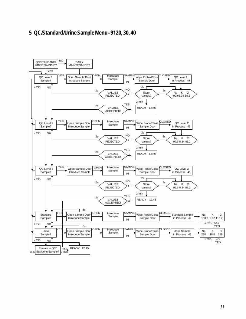
5 QC/Standard/Urine Sample Menu - 9120, 30, 40
QC/STANDARD/URINE SAMPLE?
DAILYMAINTENANCE?
YES
NO
QC Level 1Sample?
Open Sample DoorIntroduce Sample
IntroduceSample
Wipe Probe/CloseSample Door
QC Level 1in Process 49
READY 12:45
Na K Cl99.65.34 88.2
StoreValues?
VALUESREJECTED!
VALUESACCEPTED!
YES OPEN SAMPLE
IN
CLOSED
2s2s
2 min
2s
2s YES
NO
QC Level 2Sample?
Open Sample DoorIntroduce Sample
IntroduceSample Wipe Probe/Close
Sample DoorQC Level 2
in Process 49
READY 12:45
Na K Cl99.6 5.34 88.2
StoreValues?
VALUESREJECTED!
VALUESACCEPTED!
YES OPEN SAMPLE
IN
CLOSED
2s2s
2 min
2s
2sYES
NO
QC Level 3Sample?
Open Sample DoorIntroduce Sample
IntroduceSample
Wipe Probe/CloseSample Door
QC Level 3in Process 49
READY 12:45
Na K Cl99.6 5.34 88.2
StoreValues?
VALUESREJECTED!
VALUESACCEPTED!
YES OPEN SAMPLE
IN
CLOSED
2s
2s
2 min
2s
2s YES
NO
NO
NO
NO
StandardSample?
Open Sample DoorIntroduce Sample
IntroduceSample Wipe Probe/Close
Sample DoorStandard Samplein Process 49
YES OPEN SAMPLE
IN
CLOSEDNa K Cl158.8 5.82 113.2
1 min. NO/YES
NO
UrineSample?
Open Sample DoorIntroduce Sample
IntroduceSample Wipe Probe/Close
Sample DoorUrine Samplein Process 49
YES OPEN SAMPLE
IN
CLOSEDNa K Cl238 18.8 198
1 min. NO/YESNO
Remain in QC/Std/Urine Sample?
READY 12:45NO/2 min.
5s
5s
YES
2 min.
2 min.
2 min.
2 min.
2 min.
12
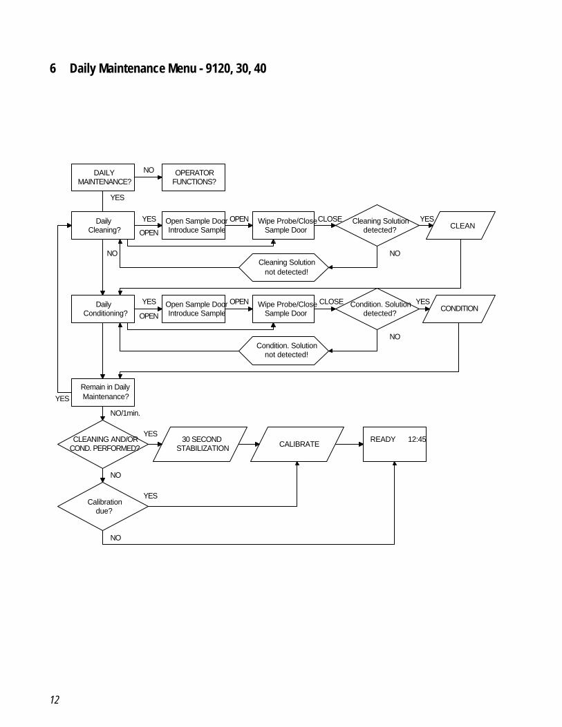
6 Daily Maintenance Menu - 9120, 30, 40
DAILYMAINTENANCE?
OPERATORFUNCTIONS?
NO
DailyCleaning?
Open Sample DoorIntroduce Sample
Wipe Probe/CloseSample Door
Cleaning Solutiondetected? CLEAN
Cleaning Solutionnot detected!
YES
YES
OPEN
OPEN CLOSE YES
NO
DailyConditioning?
Open Sample DoorIntroduce Sample
Wipe Probe/CloseSample Door
Condition. Solutiondetected?
CONDITION
Condition. Solutionnot detected!
NO
YES
OPEN
OPEN CLOSE YES
NO
Remain in DailyMaintenance?YES
CLEANING AND/ORCOND. PERFORMED?
Calibrationdue?
NO/1min.
NO
30 SECONDSTABILIZATION CALIBRATE
READY 12:45
NO
YES
YES
13
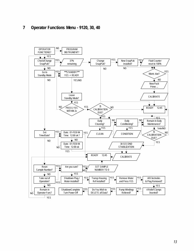
7 Operator Functions Menu - 9120, 30, 40
OPERATORFUNCTIONS?
PROGRAMINSTRUMENT?
Check/ChangeSnapPak?
37%remaining
ChangeSnapPak?
New SnapPakinstalled?
Fluid Counterreset to 100%
Go toStandby Mode
***STANDBY!***YES -> READY Maint. due?
New PackPrime ...
CALIBRATE
READY 12:45
LeaveStandby Mode?
PRESS YESWITHIN 2s
ISCALIBRATION
DUE?
DailyCleaning?
DailyConditioning?
Remain in DailyMaintenance?
CONDITIONCLEANIS
CALIBRATIONDUE?
Date: 01-FEB-94Time: 12:00 ok ?
SetTime/Date?
Date: 01-FEB-94Time: 12:00 ok
30 SECONDSTABILIZATION
CALIBRATEREADY 12:45
Are you sure?ResetSample Number?
SET SAMPLENUMBER TO 0
Take out ofOperation?
Shutdown Plug /Water installed?
Transp HousingRef installed?
Remove Waterand Press YES
All Electrodes& Plug Removed?
4 Relief ClampsInserted?
Pump WindingsRelieved?
Do You Wish toDELETE all Data?
ShutdownCompleteTurn Power Off
Remain inOperator Func?
NO
NO
NO
YESYES
NO
YES
NO
YES
NO
YESYES
YES/NO
YES
NO YES NO
YES
YES
NO NO
YES
YES
1min/NO
NO
YESNO
NO
NO
YES YES
YES
NO
NO
NO
YES
YES
YES
YESNOYES/
YES YES YES
YESYESYESYES
14
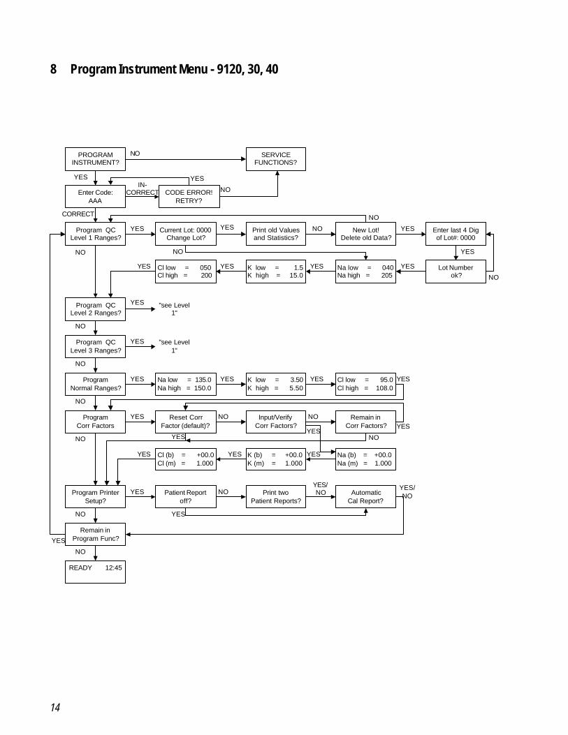
8 Program Instrument Menu - 9120, 30, 40
PROGRAMINSTRUMENT?
SERVICEFUNCTIONS?
Enter Code:AAA
CODE ERROR!RETRY?
Program QCLevel 1 Ranges?
Current Lot: 0000Change Lot?
Print old Valuesand Statistics?
New Lot!Delete old Data?
Enter last 4 Digof Lot#: 0000
Lot Numberok?
Na low = 040Na high = 205
K low = 3.50K high = 5.50
Cl low = 050Cl high = 200
Program QCLevel 2 Ranges?
Program QCLevel 3 Ranges?
ProgramNormal Ranges?
ProgramCorr Factors
Program PrinterSetup?
Remain inProgram Func?
READY 12:45
Patient Reportoff?
Print twoPatient Reports?
Reset CorrFactor (default)?
Remain inCorr Factors?
Input/VerifyCorr Factors?
Na low = 135.0Na high = 150.0
Cl low = 95.0Cl high = 108.0
K low = 1.5K high = 15.0
Na (b) = +00.0Na (m) = 1.000
K (b) = +00.0K (m) = 1.000
Cl (b) = +00.0Cl (m) = 1.000
AutomaticCal Report?
NO
NO
YES YESIN-
CORRECT
CORRECT
YES YES NO YES
NO
YES
NO
YESYESYESYES
NONO
"see Level1"
"see Level1"
NO
NO
NO
NO
NO
NO
YES
YES
YES
YES YES YES YES
YES
NOYES
NO
YESYES
NOYES
YES
YES
YES
YES
NOYES/NO
YES/NO
15
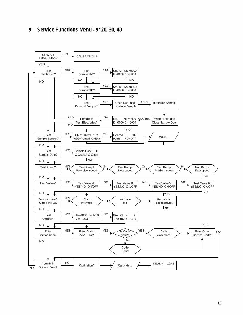
9 Service Functions Menu - 9120, 30, 40
Test Valve V:YES/NO=ON/OFF
SERVICEFUNCTIONS? CALIBRATION?
TestElectrodes?
TestStandard A?
Std. A: Na =0000K =0000 Cl =0000
Std. B: Na =0000K =0000 Cl =0000
TestStandard B?
TestExternal Sample?
Open Door andIntroduce Sample
Introduce Sample
Wipe Probe andClose Sample Door
Ext.: Na =0000K =0000 Cl =0000
Remain inTest Electrodes?
TestSample Sensor?
DRY: 80-120: 102YES=Pump/NO=Exit
External: 102Pump: NO=OFF
wash...
TestSample Door?
Sample Door: CC:Closed O:Open
Test Pump?
Test Valves?
Test Pump!Very slow speed
Test Pump!Slow speed
Test Pump!Medium speed
Test Pump!Fast speed
Test Valve A:YES/NO=ON/OFF
Test Valve B:YES/NO=ON/OFF
Test Valve R:YES/NO=ON/OFF
Test Interface?Jump Pins 2&3
TestAmplifier?
EnterService Code?
Na=-1030 K=-1200Cl = -1093
Ground = 2-2500mV = -2496
Remain inTest Interface?
Enter Code:AAA ok?
Enter OtherService Code?
READY 12:45Calibration?
Remain inService Func?
-- Test ---- Interface --
Interfaceok!
CodeAccepted!
CodeError!
Calibrate...
Is Codevalid?
NO
NO NO NO
NO NO
NO
NO
NO
NO
NO NO
NO
NO
NO NO NO
NO
NONO
NO
NO
NO NO
NO
NO
YES
YES YES YES
YES
YES
YESYES
YES
YES
YES
YES YES
YES
YES
YES
YESYES
YES
OPEN
CLOSED
2s 2s 2s
2s
16
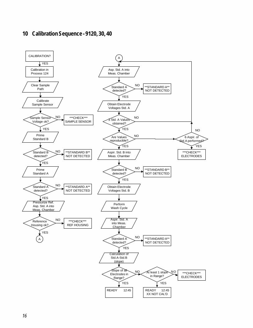
10 Calibration Sequence - 9120, 30, 40
CALIBRATION?
Calibration inProcess 124
Clear SamplePath
CalibrateSample Sensor
Sample SensorVoltage ok?
PrimeStandard B
Standard Bdetected?
PrimeStandard A
Standard Adetected?
Pressurize Ref.Asp. Std. A intoMeas. Chamber
ReferenceHousing ok?
A
***CHECK***SAMPLE SENSOR
**STANDARD B**NOT DETECTED
**STANDARD A**NOT DETECTED
***CHECK***REF HOUSING
YES
YES
YES
YES
YES
NO
NO
NO
NO
A
Asp. Std. A intoMeas. Chamber
Standard Adetected?
Obtain ElectrodeVoltages Std. A
3 Std. A Valuesobtained?
Are Valuesreproducible?
Aspir. Std. B intoMeas. Chamber
Standard Bdetected?
Obtain ElectrodeVoltages Std. B
PerformWash Cycle
Aspir. Std. Ainto Meas.Chamber
Standard Adetected?
**STANDARD A**NOT DETECTED
NO
Calculation ofStd.A-Std.B
(slope)
Slope of allElectrodes in
Range?
At least 1 slopein Range?
**STANDARD B**NOT DETECTED
NO
**STANDARD A**NOT DETECTED
NO
***CHECK***ELECTRODES
6 Aspir. ofStd.A performed?
***CHECK***ELECTRODES
READY 12:45 READY 12:45XX NOT CAL'D
NO
NO
NO
NO NO
YES YES
YES
YES
YES
YES
YES
YES
17
3.2 Software Operation - 91801 Overall Program Operating Flow - 9180
NoNo
NoNo
NoNo
NoNo
Yes
NoYes
No No
No No No No No No No
No No No
No No No No No
No No No No No No No No No
No No No No No No No No No No
Yes
Yes
Yes
Yes
Yes
Yes
Yes
No
Yes
No
Yes
No
Yes
No
Yes
No
Na K
Cl
READ
YPR
INT
FUNC
TIO
NS?
QC/
STD/
DIAL
YSAT
E/U
RINE
SAM
PLE?
DAIL
YM
AINT
ENAN
CE?
OPE
RATO
RFU
NCTI
ONS
?SE
RVIC
EFU
NCTI
ONS
?CA
LIBR
ATIO
N?
Test
Elec
trode
s?
Test
Sam
ple
Sens
or?
Test
Snap
Pak
Sens
or?
Test
Lang
uage
Swi
tch?
Test
Sam
ple
Door
?
Test
Pum
p?
Test
Valve
s?
Test
Inte
rface
?Ju
mp
Pins
2 &
3
Test
Ampl
ifier?
Ente
rSe
rvice
Cod
e?
Rem
ain
inSe
rvice
Fun
c.?
Prin
t las
tSa
mpl
e Re
port?
Prin
tCa
l. Re
port?
Prin
t QC
Valu
esan
d St
atist
ics?
Rem
ain
in P
rint
Func
tions
?
QC
Leve
l 1Sa
mpl
e?
QC
Leve
l 2Sa
mpl
e?
QC
Leve
l 3Sa
mpl
e?
Stan
dard
Sam
ple?
Bica
rbon
ate
Sam
ple?
Acet
ate
Sam
ple?
Urin
eSa
mpl
e?
Perfo
rm D
aily
Clea
ning
?
Perfo
rm D
aily
Cond
itioni
ng?
Rem
ain
in D
aily
Mai
nten
ance
?
CALI
BRAT
E...
Chec
k/Ch
ange
Snap
Pak?
Go
toSt
andb
y Mod
e?
Set
Tim
e/Da
te?
Sele
ct P
aram
eter
Conf
igur
atio
n?
Rese
tSa
mpl
e Nu
mbe
r?
Take
Out
of
Ope
ratio
n?
PRO
GRA
MIN
STRU
MEN
T?
Ente
r Cod
e:AA
A
Prog
ram
QC
Leve
l 1 R
ange
s?
Prog
ram
QC
Leve
l 2 R
ange
s?
Prog
ram
QC
Leve
l 3 R
ange
s?
Prog
ram
Norm
al R
ange
s?
Prog
ram
Corr.
Fac
tors
?
Prog
ram
Bica
rb.
Corr
Fact
ors?
Prog
ram
Ace
tate
Corr
Fact
ors?
Prog
ram
Urin
eCo
rr Fa
ctor
s?
Prog
ram
Prin
ter S
etup
?
CALI
BRAT
E...
Rem
ain
in Q
C/St
d/Ur
ine
Sam
ple?
Prog
ram
Inte
rface
?
Rem
ain
inPr
ogra
m F
unc.
?
No No
Rem
ain
inO
pera
tor F
unc.
?
No
18
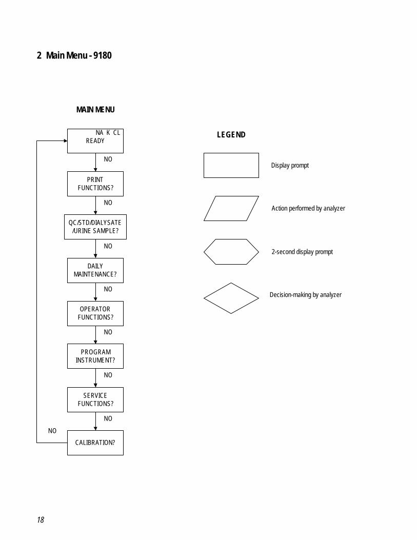
2 Main Menu - 9180
NA K CLREADY
PRINTFUNCTIONS?
QC/STD/DIALYSATE/URINE SAMPLE?
DAILYMAINTENANCE?
OPERATORFUNCTIONS?
PROGRAMINSTRUMENT?
SERVICEFUNCTIONS?
CALIBRATION?
MAIN MENU
LEGEND
Display prompt
Action performed by analyzer
2-second display prompt
Decision-making by analyzer
NO
NO
NO
NO
NO
NO
NO
NO
19
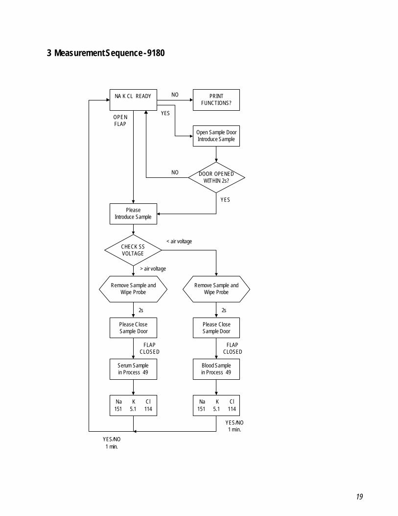
3 Measurement Sequence - 9180
NA K CL READY
DOOR OPENEDWITHIN 2s?
Remove Sample andWipe Probe
PRINTFUNCTIONS?
Open Sample DoorIntroduce Sample
PleaseIntroduce Sample
CHECK SSVOLTAGE
Remove Sample andWipe Probe
Please CloseSample Door
Please CloseSample Door
Serum Samplein Process 49
Blood Samplein Process 49
Na K Cl151 5.1 114
Na K Cl151 5.1 114
NO
YESOPENFLAP
NO
YES
< air voltage
> air voltage
2s 2s
FLAPCLOSED
FLAPCLOSED
YES/NO1 min.
YES/NO1 min.
20
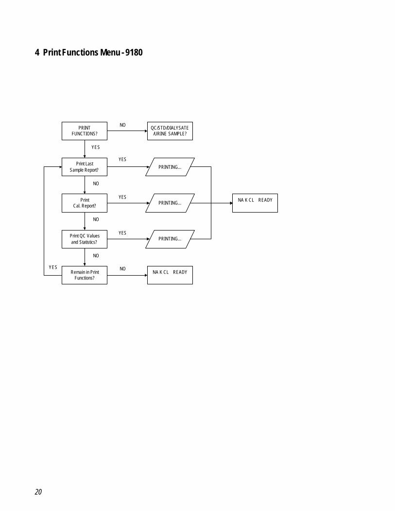
4 Print Functions Menu - 9180
PRINTFUNCTIONS?
PRINTING...
QC/STD/DIALYSATE/URINE SAMPLE?
Print LastSample Report?
PrintCal. Report?
Print QC Valuesand Statistics?
Remain in PrintFunctions?
NA K CL READY
NA K CL READYPRINTING...
PRINTING...
NO
NO
NO
NO
NO
YES
YES
YES
YES
YES
21
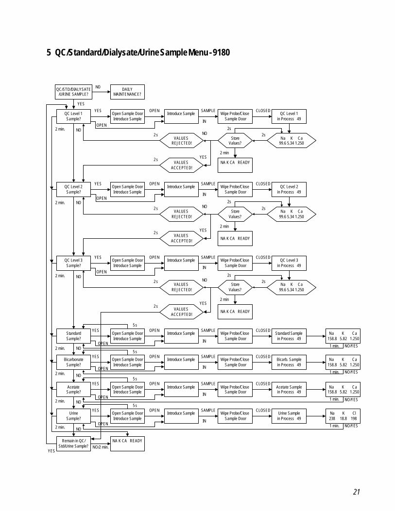
5 QC/Standard/Dialysate/Urine Sample Menu - 9180
QC/STD/DIALYSATE/URINE SAMPLE?
DAILYMAINTENANCE?
YES
NO
QC Level 1Sample?
Open Sample DoorIntroduce Sample
Introduce Sample Wipe Probe/CloseSample Door
QC Level 1in Process 49
NA K CA READY
Na K Ca99.6 5.34 1.250
StoreValues?
VALUESREJECTED!
VALUESACCEPTED!
YES OPEN SAMPLE
IN
CLOSED
2s2s
2 min
2 s
2 s YES
NO
QC Level 2Sample?
Open Sample DoorIntroduce Sample
Introduce Sample Wipe Probe/CloseSample Door
QC Level 2in Process 49
NA K CA READY
Na K Ca99.6 5.34 1.250
StoreValues?
VALUESREJECTED!
VALUESACCEPTED!
YES OPEN SAMPLE
IN
CLOSED
2s
2s
2 min
2 s
2 s YES
NO
QC Level 3Sample?
Open Sample DoorIntroduce Sample
Introduce Sample Wipe Probe/CloseSample Door
QC Level 3in Process 49
NA K CA READY
Na K Ca99.6 5.34 1.250
StoreValues?
VALUESREJECTED!
VALUESACCEPTED!
YES OPEN SAMPLE
IN
CLOSED
2s2s
2 min
2 s
2 sYES
NO
NO
NO
NO
StandardSample?
Open Sample DoorIntroduce Sample
Introduce Sample Wipe Probe/CloseSample Door
Standard Samplein Process 49
YES OPEN SAMPLE
IN
CLOSEDNa K Ca
158.8 5.82 1.250
1 min. NO/YESNO
BicarbonateSample?
Open Sample DoorIntroduce Sample
Introduce Sample Wipe Probe/CloseSample Door
Bicarb. Samplein Process 49
YES OPEN SAMPLE
IN
CLOSEDNa K Ca
158.8 5.82 1.250
1 min. NO/YESNO
5 s
5 s
YES
2 min.
2 min.
2 min.
2 min.
2 min.
NO
UrineSample?
Open Sample DoorIntroduce Sample
Introduce Sample Wipe Probe/CloseSample Door
Urine Samplein Process 49
YES OPEN SAMPLE
IN
CLOSEDNa K Cl238 18.8 198
1 min. NO/YESNO
Remain in QC/Std/Urine Sample?
NA K CA READYNO/2 min.
5 s
2 min.
AcetateSample?
Open Sample DoorIntroduce Sample
Introduce Sample Wipe Probe/CloseSample Door
Acetate Samplein Process 49
YES OPEN SAMPLE
IN
CLOSEDNa K Ca
158.8 5.82 1.250
1 min. NO/YES
5 s
2 min.
OPEN
OPEN
OPEN
OPEN
OPEN
OPEN
OPEN
22
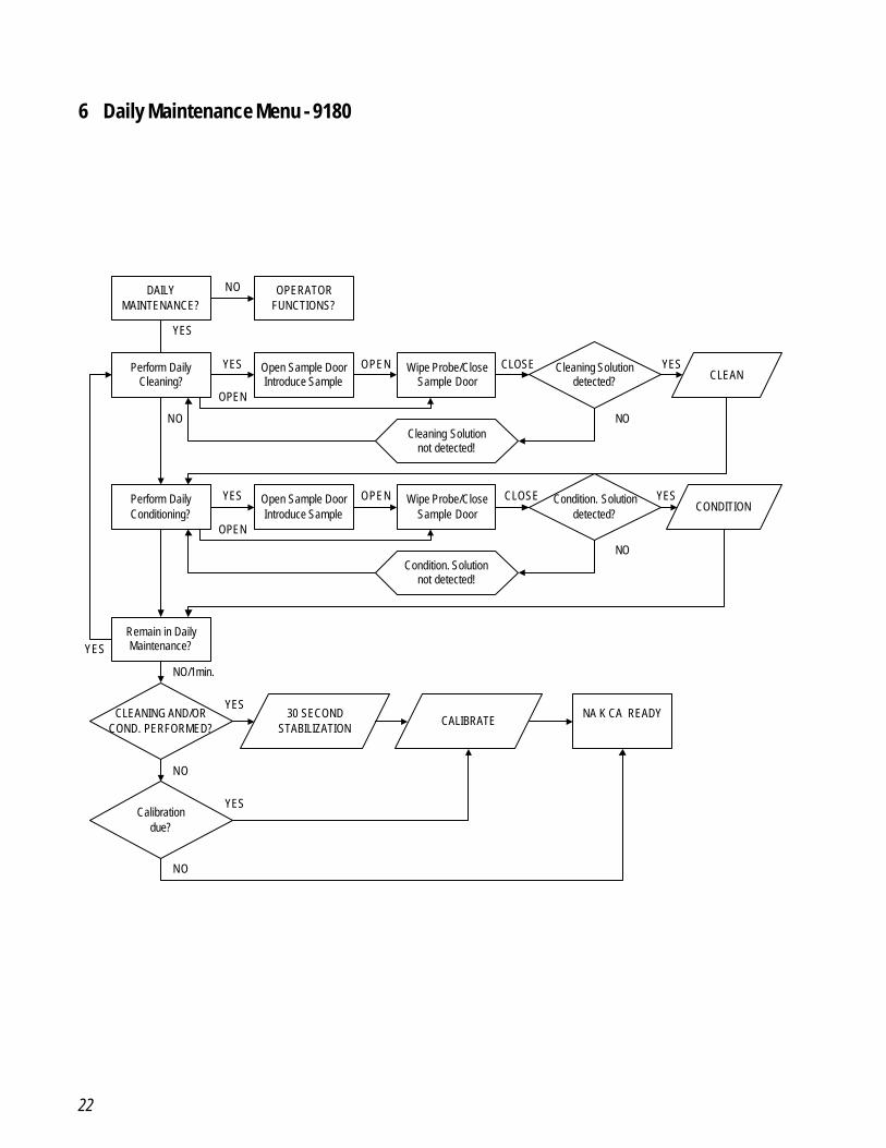
6 Daily Maintenance Menu - 9180
DAILYMAINTENANCE?
OPERATORFUNCTIONS?
NO
Perform DailyCleaning?
Open Sample DoorIntroduce Sample
Wipe Probe/CloseSample Door
Cleaning Solutiondetected? CLEAN
Cleaning Solutionnot detected!
YES
YES
OPEN
OPEN CLOSE YES
NO
Perform DailyConditioning?
Open Sample DoorIntroduce Sample
Wipe Probe/CloseSample Door
Condition. Solutiondetected?
CONDITION
Condition. Solutionnot detected!
NO
YES
OPEN
OPEN CLOSE YES
NO
Remain in DailyMaintenance?YES
CLEANING AND/ORCOND. PERFORMED?
Calibrationdue?
NO/1min.
NO
30 SECONDSTABILIZATION
CALIBRATENA K CA READY
NO
YES
YES
23
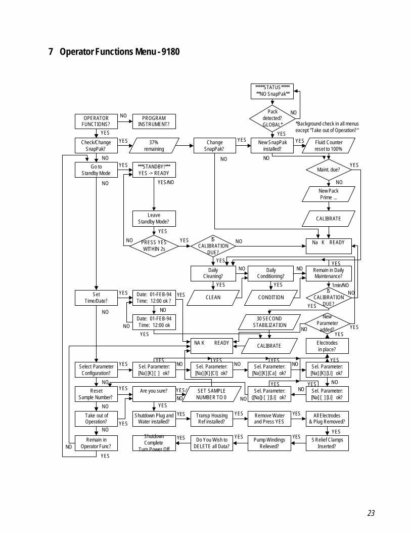
7 Operator Functions Menu - 9180
OPERATORFUNCTIONS?
PROGRAMINSTRUMENT?
Check/ChangeSnapPak?
37%remaining
ChangeSnapPak?
New SnapPakinstalled?
Fluid Counterreset to 100%
Go toStandby Mode
***STANDBY!***YES -> READY
Maint. due?
New PackPrime ...
CALIBRATE
Na K READY
LeaveStandby Mode?
PRESS YESWITHIN 2s
ISCALIBRATION
DUE?
DailyCleaning?
DailyConditioning?
Remain in DailyMaintenance?
CONDITIONCLEANIS
CALIBRATIONDUE?
Date: 01-FEB-94Time: 12:00 ok ?
SetTime/Date?
Date: 01-FEB-94Time: 12:00 ok
30 SECONDSTABILIZATION
CALIBRATENA K READY
Are you sure?ResetSample Number?
SET SAMPLENUMBER TO 0
Take out ofOperation?
Shutdown Plug andWater installed?
Transp HousingRef installed?
Remove Waterand Press YES
All Electrodes& Plug Removed?
5 Relief ClampsInserted?
Pump WindingsRelieved?
Do You Wish toDELETE all Data?
ShutdownComplete
Turn Power Off
Remain inOperator Func?
NO
NO
NO
YESYES
NO
YES
NO
YES
NO
YESYES
YES/NO
YES
NO YES NO
YES
YES
NO NO
YES
YES
1min/NONO
YESNO
NO
NO
YES YES
YES
NO
NO
NO
YES
YES
YES
YESNOYES/
YES YES
YESYESYESYES
Packdetected?GLOBAL*
*****STATUS*******NO SnapPak**
YES
NO
*Background check in all menusexcept "Take out of Operation?"
YES
Select ParameterConfiguration?
Sel. Parameter:[Na] [K] [ ] ok?
Sel. Parameter:[Na] [K] [Cl] ok?
Sel. Parameter:[Na] [K] [Ca] ok?
Sel. Parameter:([Na]) [ ] [Li] ok?
Sel. Parameter:[Na] [ ] [Li] ok?
Sel. Parameter:[Na] [K] [Li] ok?
Electrodesin place?
NewParameter
added?
NO
YES NO NO NO
NONO
NO
YES
YESYES YES YES
YES
YESYESNO

24
8 Program Instrument Menu - 9180
PROGRAMINSTRUMENT?
SERVICEFUNCTIONS?
Enter Code:AAA
CODE ERROR!RETRY?
Program QCLevel 1 Ranges?
Current Lot: 0000Change Lot?
Print old Valuesand Statistics?
New Lot!Delete old Data?
Enter last 4 Digof Lot#: 0000
Enter last 4 Digof Lot#: 0000 ok?
Na low = 040 Na high = 205 ok?
K low = 03.5 K high = 05.1 ok?
Cl low = 050 Cl high = 200 ok?
Program QCLevel 2 Ranges?
Program QCLevel 3 Ranges?
ProgramNormal Ranges?
ProgramCorr Factors
Program PrinterSetup?
Remain inProgram Func?
NA K READY
Patient Reportoff?
Print twoPatient Reports?
Reset CorrFactor (default)?
Remain inCorr Factors?
Input/VerifyCorr Factors?
Na low = 136 Na high = 145 ok?
K low = 1.5 K high = 15.0 ok?
Na (b) = +00.0Na (m) = 1.000
K (b) = +00.0K (m) = 1.000
AutomaticCal Report?
NO
NO
YES YESIN-
CORRECT
CORRECT
YES YES NO YESNO
YES
NO
YESYESYESNO
NONO
"see Level 1"
"see Level 1"
NO
NO
NO
NO
NO
NO
YES
YES
YES
YES YES YES
YES
NO
NO YES
YES
NOYES
YES
YES
NOYES/NO
YES/NO
AdditionalParameters?
YES
Ca low = 0.2 Ca high = 5.0 ok?
Li low = 0.1 Li high = 6.0 ok?
YESYES YES
Program Bicarb.Corr Factors
Reset Bicarb.Factor (default)?
Remain inBicarb Factors?
Input/VerifyBicarb. Factors?
Na (b) = +00.0Na (m) = 1.000
K (b) = +00.0K (m) = 1.000
YES
NO
NO YES
YES
NOYES
YES
Program AcetateCorr Factors
Reset AcetateFactor (default)?
Remain inAcetate Factors?
Input/VerifyAcetate Factors?
Na (b) = +00.0Na (m) = 1.000
K (b) = +00.0K (m) = 1.000
YES
NO
NO YES
YES
NOYES
YES
Enter CommentLine?
Enter Comment: _
ProgramInterface?
ActivateData Link?
YES
NO
YES
NO YES
YES/NO
YES
YES
YES
YES
NO
NO
Program UrineCorr Factors
NO
Reset UrineFactor (default)?
Remain inUrine Factors?
Input/VerifyUrine Factors?
Na (b) = +00.0Na (m) = 1.000
K (b) = +00.0K (m) = 1.000
YES
NO
NO YES
YES
NOYES
YES YES
25
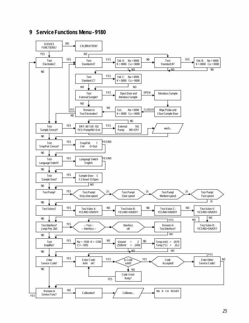
9 Service Functions Menu - 9180
Test Valve C:YES/NO=ON/OFF
SERVICEFUNCTIONS? CALIBRATION?
TestElectrodes?
TestStandard A?
Std. A: Na = 0000K = 0000 Ca = 0000
Std. C: Na = 0000K = 0000 Ca = 0000
TestStandard C?
TestExternal Sample?
Open Door andIntroduce Sample
Introduce Sample
Wipe Probe andClose Sample Door
Ext.: Na = 0000K = 0000 Ca = 0000
Remain inTest Electrodes?
TestSample Sensor?
DRY: 80-120: 102YES=Pump/NO=Exit
External: 102Pump: NO=OFF wash...
TestSample Door?
Sample Door: CC:Closed O:Open
Test Pump?
Test Valves?
Test Pump!Very slow speed
Test Pump!Slow speed
Test Pump!Medium speed
Test Pump!Fast speed
Test Valve A:YES/NO=ON/OFF
Test Valve B:YES/NO=ON/OFF
Test Valve V:YES/NO=ON/OFF
Test Interface?Jump Pins 2&3
TestAmplifier?
EnterService Code?
Na = -1030 K = -1200 Cl = -1093
Ground = 2-2500mV = -2496
Remain inTest Interface?
Enter Code:AAA ok?
Enter OtherService Code?
NA K CA READYCalibration?
Remain inService Func?
-- Test ---- Interface --
Interfaceok!
CodeAccepted!
Calibrate...
Is Codevalid?
NO
NONO
NO NO
NO
NO
NO
NO
NO NO
NO
NO
NO NO NO
NO
NONO
NO
NO
NO
NO
NO
NO
YES
YES YES YES
YES
YES
YESYES
YES
YES
YES
YES YES
YES
YES
YES
YESYES
YES
OPEN
CLOSED
2s 2s 2s
2s
TestSnapPak Sensor?
TestLanguage Switch?
NO
NO
SnapPak: II=In O=Out
Language SwitchEnglish
YES
YES YES/NO
YES/NO
Std. B: Na = 0000K = 0000 Ca = 0000
TestStandard B?
YESNO
NO
Test Valve R:YES/NO=ON/OFF
NO
Code Error!Retry?YES
NO
NO NO
NO
Temp (mV) = -2670Temp (°C) = 26.2
NO
NO
26
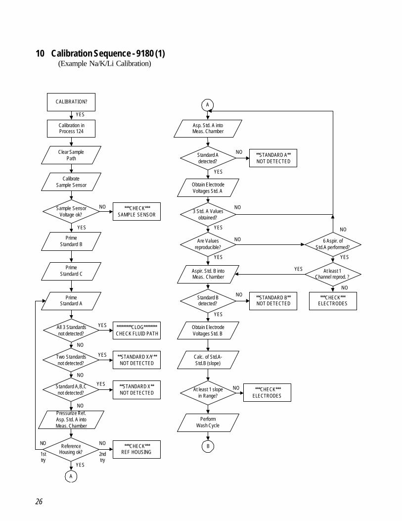
10 Calibration Sequence - 9180 (1) (Example Na/K/Li Calibration)
CALIBRATION?
Calibration inProcess 124
Clear SamplePath
CalibrateSample Sensor
Sample SensorVoltage ok?
PrimeStandard B
Two Standardsnot detected?
PrimeStandard A
All 3 Standardsnot detected?
Pressurize Ref.Asp. Std. A intoMeas. Chamber
ReferenceHousing ok?
A
***CHECK***SAMPLE SENSOR
**STANDARD X/Y**NOT DETECTED
*********CLOG********CHECK FLUID PATH
***CHECK***REF HOUSING
YES
YES
YES
YES
NO
NO
NO
NO
A
Asp. Std. A intoMeas. Chamber
Standard Adetected?
Obtain ElectrodeVoltages Std. A
3 Std. A Valuesobtained?
Are Valuesreproducible?
Aspir. Std. B intoMeas. Chamber
Standard Bdetected?
Obtain ElectrodeVoltages Std. B
Calc. of Std.A-Std.B (slope)
**STANDARD B**NOT DETECTED
NO
**STANDARD A**NOT DETECTED
NO
***CHECK***ELECTRODES
6 Aspir. ofStd.A performed?
NO
NO
NO
NO
YES
YES
YES
YES
YES
Standard A,B,Cnot detected?
**STANDARD X**NOT DETECTED
YES
NO
PrimeStandard C
YES
NO
1sttry
2ndtry
At least 1Channel reprod. ?
NO
YES
At least 1 slopein Range?
***CHECK***ELECTRODES
PerformWash Cycle
B
27
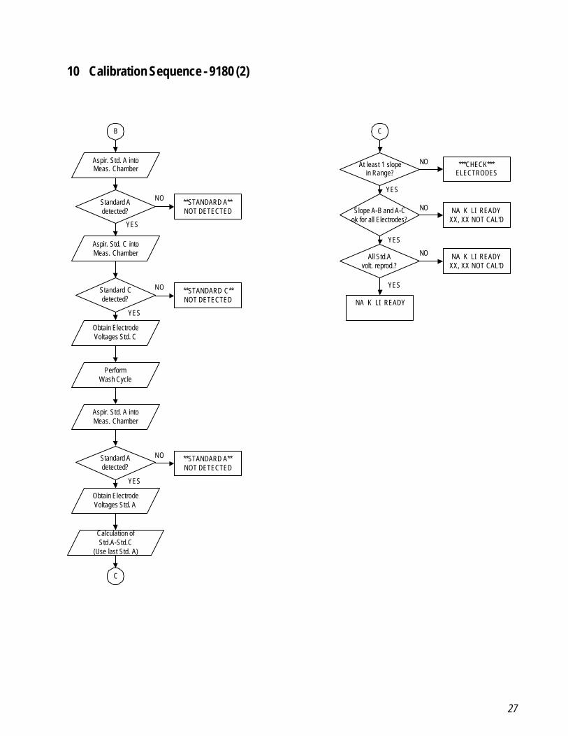
10 Calibration Sequence - 9180 (2)
Aspir. Std. A intoMeas. Chamber
Standard Adetected?
**STANDARD A**NOT DETECTED
NO
Calculation ofStd.A-Std.C
(Use last Std. A)
All Std.Avolt. reprod.?
At least 1 slopein Range?
***CHECK***ELECTRODES
NA K LI READY
NA K LI READYXX, XX NOT CAL'D
NO
YES
YES
B
Aspir. Std. C intoMeas. Chamber
Standard Cdetected?
**STANDARD C**NOT DETECTED
NO
Obtain ElectrodeVoltages Std. C
PerformWash Cycle
Aspir. Std. A intoMeas. Chamber
Standard Adetected?
**STANDARD A**NOT DETECTED
NO
Obtain ElectrodeVoltages Std. A
Slope A-B and A-Cok for all Electrodes?
NA K LI READYXX, XX NOT CAL'D
C
C
YES
YES
YES
YES
NO
NO
28
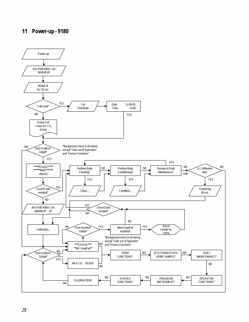
11 Power-up - 9180
Power-up
AVL9180 A80X1.AAWARM UP
All dots litfor 1/2 sec.
Cold start?Set
Time/DateDate: 1-JAN-95Time: 12:00
Power Fail1-Nov-95 1:12
(Print)
Pack in place?Global*
*****PLEASE************WAIT*******
(Wash)
Perform DailyCleaning?
Perform DailyConditioning?
Is Calibrationdue?
Clean/Cond.needed?
Clean... Condition...
Remain in DailyMaintenance?
Stabilizing30 sec.
AVL9180 A80X1.AAWARM UP 59
Clean/Cond.needed?
Calibration...Pack inserted?
Global*New SnapPak
installed?
Resetcounter to
100%
Pack in place?Global*
****STATUS******NO SnapPak**
NA K CA READY
PRINTFUNCTIONS?
QC/STD/DIALYSATE/URINE SAMPLE?
DAILYMAINTENANCE?
CALIBRATION?SERVICE
FUNCTIONS?PROGRAM
INSTRUMENT?OPERATOR
FUNCTIONS?
YES
YESNO
NO
YES
YES
YES YES
NO NO
YES
NO
1min
YES
NO
YES
NO
NO YES YES
NO
YES
NO
NO
NO
NO
NO NO
NO
NO
NO
NO
*Background check in all menusexcept "Take out of Operation"and "Service Functions"
*Background check in all menusexcept "Take out of Operation"and "Service Functions"
NO
29
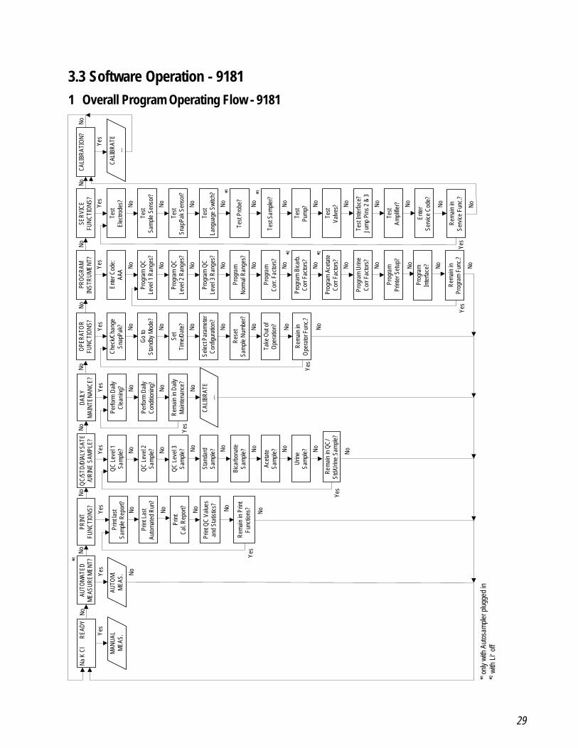
3.3 Software Operation - 91811 Overall Program Operating Flow - 9181
Yes
NoNo
NoNo
NoNo
No
Yes
NoNo No No
No No No No No
No No No No No No No No No
No No No No No No No No No No
Yes
Yes
Yes
Yes
Yes
Yes
No
Yes
No
Yes
No
QC/
STD/
DIAL
YSAT
E/U
RINE
SAM
PLE?
OPE
RATO
RFU
NCTI
ONS
?SE
RVIC
EFU
NCTI
ONS
?CA
LIBR
ATIO
N?
Test
Elec
trode
s?
Test
Sam
ple
Sens
or?
Test
Snap
Pak
Sens
or?
Test
Lang
uage
Swi
tch?
Test
Pro
be?
Test
Sam
pler
?
Test
Pum
p?
Test
Valve
s?
Test
Inte
rface
?Ju
mp
Pins
2 &
3
Test
Ampl
ifier?
Ente
rSe
rvice
Cod
e?
QC
Leve
l 1Sa
mpl
e?
QC
Leve
l 2Sa
mpl
e?
QC
Leve
l 3Sa
mpl
e?
CALI
BRAT
E...
Chec
k/Cha
nge
Snap
Pak?
Go
toSt
andb
y M
ode?
Set
Tim
e/Da
te?
Sele
ct P
aram
eter
Conf
igur
atio
n?
Rese
tSa
mpl
e Nu
mbe
r?
Take
Out
of
Ope
ratio
n?
PRO
GRA
MIN
STRU
MEN
T?
Ente
r Cod
e:AA
A
Prog
ram
QC
Leve
l 1 R
ange
s?
Prog
ram
QC
Leve
l 2 R
ange
s?
Prog
ram
QC
Leve
l 3 R
ange
s?
Prog
ram
Norm
al R
ange
s?
Prog
ram
Corr.
Fac
tors
?
Prog
ram
Bica
rb.
Corr
Fact
ors?
Prog
ram
Ace
tate
Corr
Fact
ors?
Prog
ram
Urin
eCo
rr Fa
ctor
s?
Prog
ram
Prin
ter S
etup
?
CALI
BRAT
E...
Prog
ram
Inte
rface
?
Rem
ain
inPr
ogra
m F
unc.
?
No No
Rem
ain
inO
pera
tor F
unc.?
No
No No NoYes
DAIL
YM
AINT
ENAN
CE?
Perfo
rm D
aily
Clea
ning
?
Perfo
rm D
aily
Cond
itioni
ng?
Rem
ain
in D
aily
Mai
nten
ance
?
No
Rem
ain
inSe
rvice
Fun
c.?
NoNo
Yes
Na K
Cl
R
EADY
AUTO
MAT
EDM
EASU
REM
ENT?
Yes
MAN
UAL
MEA
S.AU
TOM
.M
EAS.
Yes
No
Yes
No
PRIN
TFU
NCTI
ONS
?
Prin
t las
tSa
mpl
e Re
port?
Prin
t Las
tAu
tom
ated
Run
?
Prin
tCa
l. Re
port? No
Prin
t QC
Valu
esan
d St
atist
ics?
No
Rem
ain
in P
rint
Func
tions
?
No
No No No No No
Stan
dard
Sam
ple?
Bica
rbon
ate
Sam
ple?
Acet
ate
Sam
ple?
Urin
eSa
mpl
e?
Rem
ain
in Q
C/St
d/Ur
ine
Sam
ple?
*1
*1 *1
*2 *2
*1 on
ly wi
th A
utos
ampl
er p
lugg
ed in
*2 with
Li+ o
ff
30
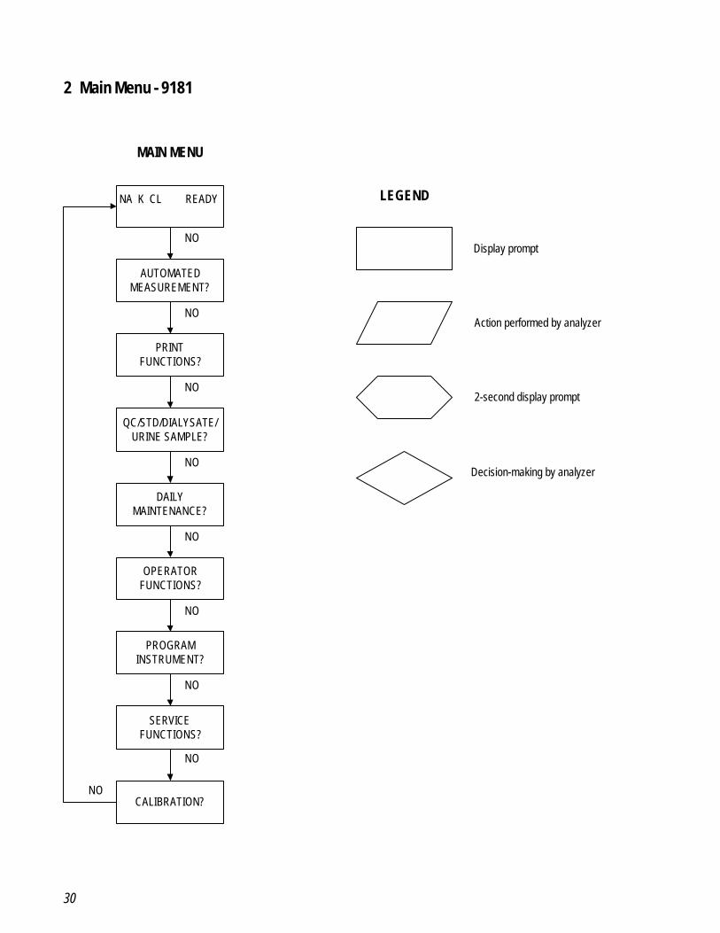
2 Main Menu - 9181
NA K CL READY
AUTOMATEDMEASUREMENT?
PRINTFUNCTIONS?
QC/STD/DIALYSATE/URINE SAMPLE?
DAILYMAINTENANCE?
OPERATORFUNCTIONS?
PROGRAMINSTRUMENT?
SERVICEFUNCTIONS?
MAIN MENU
LEGEND
Display prompt
Action performed by analyzer
2-second display prompt
Decision-making by analyzer
NO
NO
NO
NO
NO
NO
NO
NOCALIBRATION?
NO
31
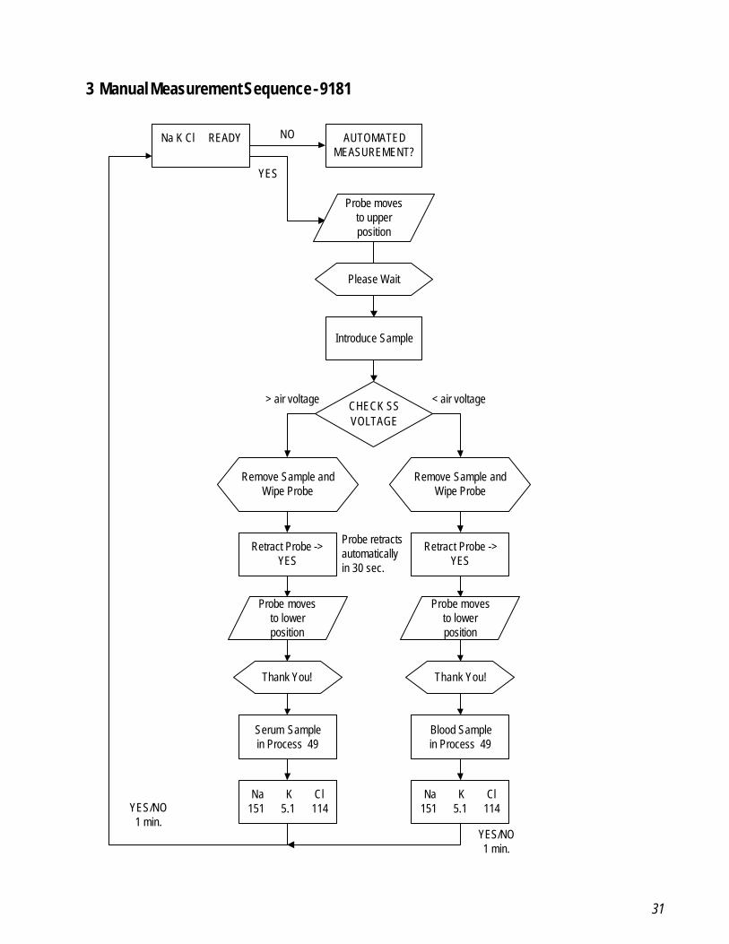
3 Manual Measurement Sequence - 9181
Na K Cl READY
Remove Sample andWipe Probe
AUTOMATEDMEASUREMENT?
Introduce Sample
CHECK SSVOLTAGE
Remove Sample andWipe Probe
Retract Probe ->YES
Retract Probe ->YES
Serum Samplein Process 49
Blood Samplein Process 49
Na K Cl151 5.1 114
Na K Cl151 5.1 114
NO
YES
< air voltage> air voltage
YES/NO1 min.
YES/NO1 min.
Probe movesto upperposition
Please Wait
Probe retractsautomaticallyin 30 sec.
Probe movesto lowerposition
Probe movesto lowerposition
Thank You! Thank You!
32
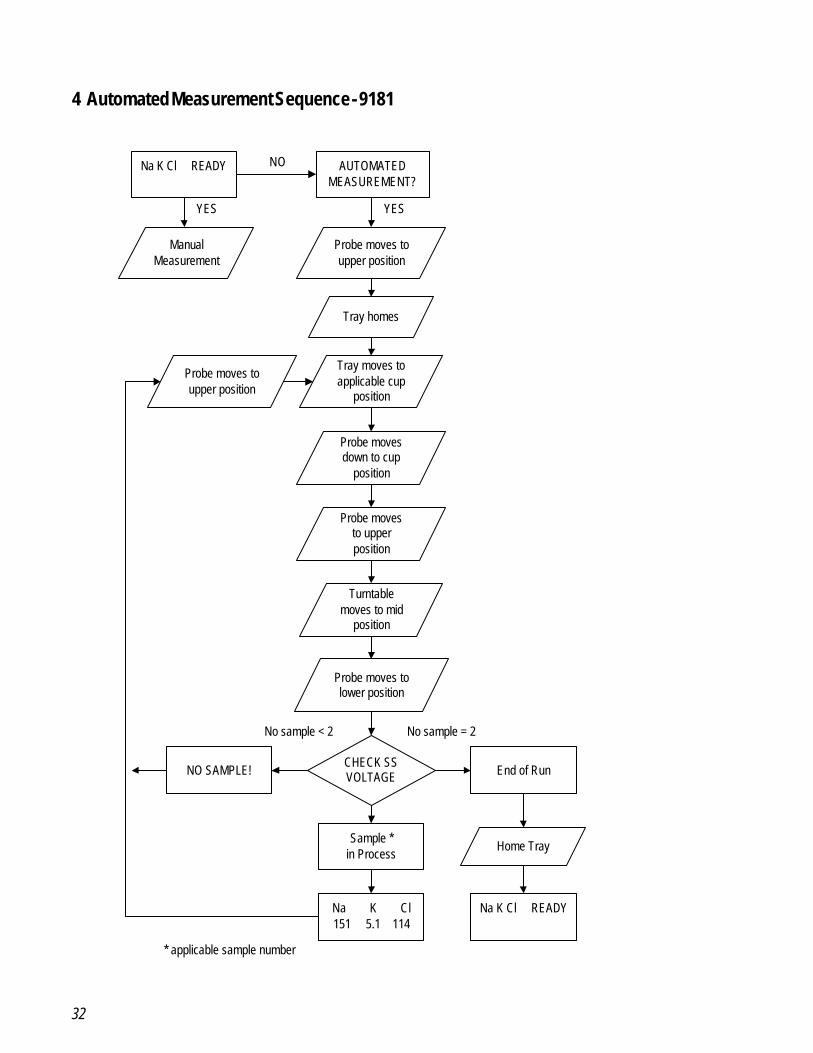
4 Automated Measurement Sequence - 9181
Na K Cl READY AUTOMATEDMEASUREMENT?
CHECK SSVOLTAGE
Sample *in Process
NO SAMPLE!
Na K Cl151 5.1 114
NO
YES
No sample = 2No sample < 2
Probe moves toupper position
ManualMeasurement
YES
Tray homes
Tray moves toapplicable cup
position
Probe movesdown to cup
position
Turntablemoves to mid
position
Probe moves tolower position
End of Run
Home Tray
Na K Cl READY
Probe moves toupper position
* applicable sample number
Probe movesto upperposition
33
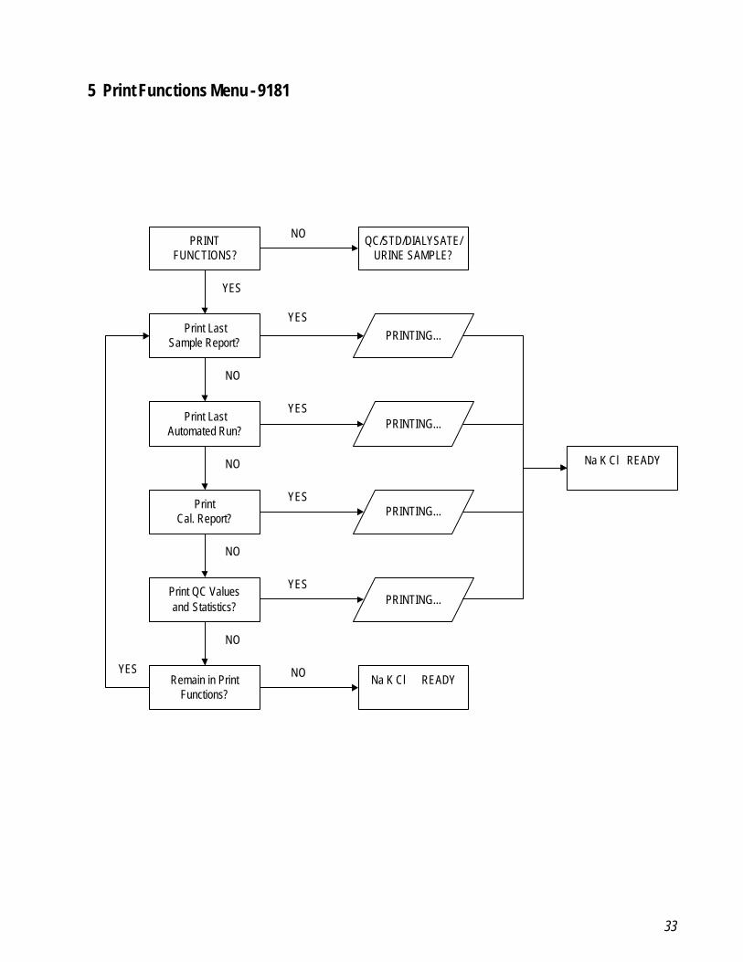
5 Print Functions Menu - 9181
PRINTFUNCTIONS?
PRINTING...
QC/STD/DIALYSATE/URINE SAMPLE?
Print LastSample Report?
PrintCal. Report?
Print QC Valuesand Statistics?
Remain in PrintFunctions?
Na K Cl READY
Na K Cl READY
PRINTING...
PRINTING...
NO
NO
NO
NO
NO
YES
YES
YES
YES
YES
Print LastAutomated Run? PRINTING...
NO
YES
34
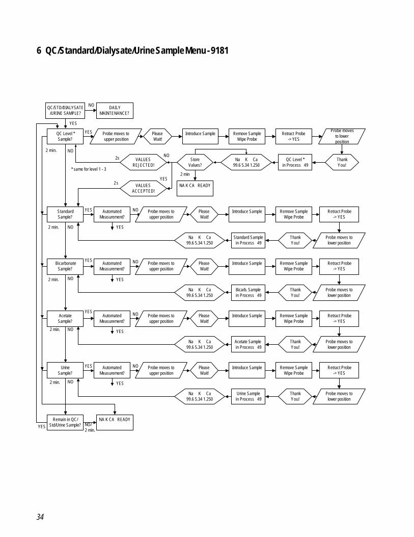
6 QC/Standard/Dialysate/Urine Sample Menu - 9181
QC/STD/DIALYSATE/URINE SAMPLE?
DAILYMAINTENANCE?
YES
NO
QC Level *Sample?
Introduce Sample Remove SampleWipe Probe
QC Level *in Process 49
NA K CA READY
Na K Ca99.6 5.34 1.250
StoreValues?
VALUESREJECTED!
VALUESACCEPTED!
YES
2 min
2s
2 sYES
NONO
StandardSample?
NO
BicarbonateSample?
YES
NO
YES
2 min.
2 min.
2 min.
NO
UrineSample?
YES
NO
Remain in QC/Std/Urine Sample?
NA K CA READYNO/2 min.
2 min.
AcetateSample?
YES
2 min.
Probe moves toupper position
PleaseWait!
Retract Probe-> YES
Probe movesto lowerposition
ThankYou!
* same for level 1 - 3
AutomatedMeasurement?
Introduce Sample Remove SampleWipe Probe
NO Probe moves toupper position
PleaseWait!
Retract Probe-> YES
YES
YES
Probe moves tolower position
Standard Samplein Process 49
Na K Ca99.6 5.34 1.250
ThankYou!
AutomatedMeasurement?
Introduce Sample Remove SampleWipe Probe
NO Probe moves toupper position
PleaseWait!
Retract Probe-> YES
YES
Probe moves tolower position
Bicarb. Samplein Process 49
Na K Ca99.6 5.34 1.250
ThankYou!
AutomatedMeasurement?
Introduce Sample Remove SampleWipe Probe
NO Probe moves toupper position
PleaseWait!
Retract Probe-> YES
YES
Probe moves tolower position
Acetate Samplein Process 49
Na K Ca99.6 5.34 1.250
ThankYou!
AutomatedMeasurement?
Introduce Sample Remove SampleWipe Probe
NO Probe moves toupper position
PleaseWait!
Retract Probe-> YES
YES
Probe moves tolower position
Urine Samplein Process 49
Na K Ca99.6 5.34 1.250
ThankYou!
35
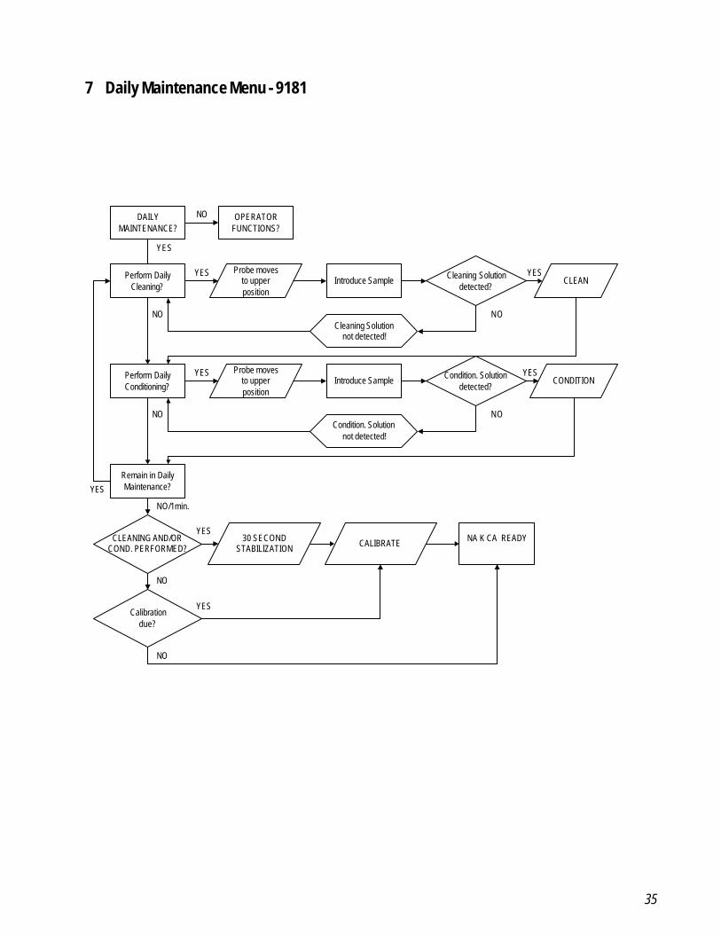
7 Daily Maintenance Menu - 9181
DAILYMAINTENANCE?
OPERATORFUNCTIONS?
NO
Perform DailyCleaning?
Introduce Sample Cleaning Solutiondetected?
CLEAN
Cleaning Solutionnot detected!
YES
YES YES
NO
Perform DailyConditioning?
Introduce Sample Condition. Solutiondetected?
CONDITION
Condition. Solutionnot detected!
NO
YES YES
NO
Remain in DailyMaintenance?YES
CLEANING AND/ORCOND. PERFORMED?
Calibrationdue?
NO/1min.
NO
30 SECONDSTABILIZATION CALIBRATE NA K CA READY
NO
YES
YES
Probe movesto upperposition
Probe movesto upperposition
NO
36
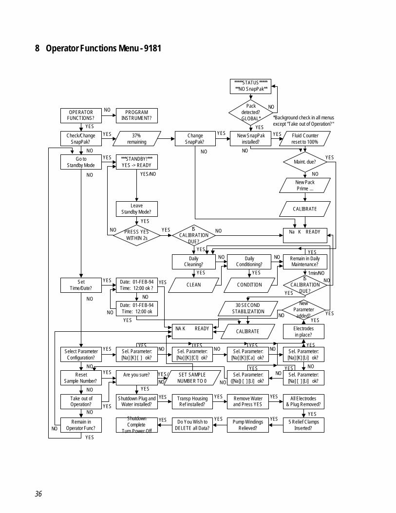
8 Operator Functions Menu - 9181
OPERATORFUNCTIONS?
PROGRAMINSTRUMENT?
Check/ChangeSnapPak?
37%remaining
ChangeSnapPak?
New SnapPakinstalled?
Fluid Counterreset to 100%
Go toStandby Mode
***STANDBY!***YES -> READY
Maint. due?
New PackPrime ...
CALIBRATE
Na K READY
LeaveStandby Mode?
PRESS YESWITHIN 2s
ISCALIBRATION
DUE?
DailyCleaning?
DailyConditioning?
Remain in DailyMaintenance?
CONDITIONCLEANIS
CALIBRATIONDUE?
Date: 01-FEB-94Time: 12:00 ok ?
SetTime/Date?
Date: 01-FEB-94Time: 12:00 ok
30 SECONDSTABILIZATION
CALIBRATENA K READY
Are you sure?ResetSample Number?
SET SAMPLENUMBER TO 0
Take out ofOperation?
Shutdown Plug andWater installed?
Transp HousingRef installed?
Remove Waterand Press YES
All Electrodes& Plug Removed?
5 Relief ClampsInserted?
Pump WindingsRelieved?
Do You Wish toDELETE all Data?
ShutdownComplete
Turn Power Off
Remain inOperator Func?
NO
NO
NO
YESYES
NO
YES
NO
YES
NO
YESYES
YES/NO
YES
NO YES NO
YES
YES
NO NO
YES
YES
1min/NONO
YESNO
NO
NO
YES YES
YES
NO
NO
NO
YES
YES
YES
YESNOYES/
YES YES
YESYESYESYES
Packdetected?GLOBAL*
*****STATUS*******NO SnapPak**
YES
NO
*Background check in all menusexcept "Take out of Operation?"
YES
Select ParameterConfiguration?
Sel. Parameter:[Na] [K] [ ] ok?
Sel. Parameter:[Na] [K] [Cl] ok?
Sel. Parameter:[Na] [K] [Ca] ok?
Sel. Parameter:([Na]) [ ] [Li] ok?
Sel. Parameter:[Na] [ ] [Li] ok?
Sel. Parameter:[Na] [K] [Li] ok?
Electrodesin place?
NewParameter
added?
NO
YES NO NO NO
NONO
NO
YES
YESYES YES YES
YES
YESYESNO
37
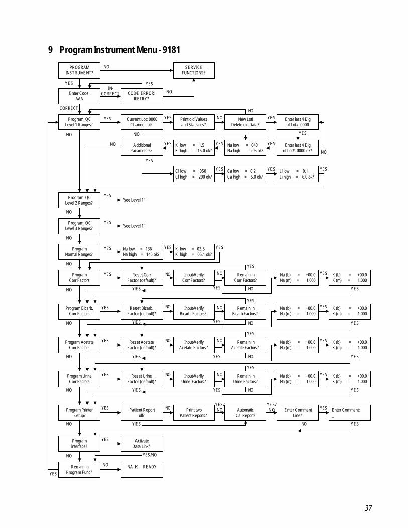
9 Program Instrument Menu - 9181
PROGRAMINSTRUMENT?
SERVICEFUNCTIONS?
Enter Code:AAA
CODE ERROR!RETRY?
Program QCLevel 1 Ranges?
Current Lot: 0000Change Lot?
Print old Valuesand Statistics?
New Lot!Delete old Data?
Enter last 4 Digof Lot#: 0000
Enter last 4 Digof Lot#: 0000 ok?
Na low = 040 Na high = 205 ok?
K low = 03.5 K high = 05.1 ok?
Cl low = 050 Cl high = 200 ok?
Program QCLevel 2 Ranges?
Program QCLevel 3 Ranges?
ProgramNormal Ranges?
ProgramCorr Factors
Program PrinterSetup?
Remain inProgram Func?
NA K READY
Patient Reportoff?
Print twoPatient Reports?
Reset CorrFactor (default)?
Remain inCorr Factors?
Input/VerifyCorr Factors?
Na low = 136 Na high = 145 ok?
K low = 1.5 K high = 15.0 ok?
Na (b) = +00.0Na (m) = 1.000
K (b) = +00.0K (m) = 1.000
AutomaticCal Report?
NO
NO
YES YESIN-
CORRECT
CORRECT
YES YES NO YESNO
YES
NO
YESYESYESNO
NONO
"see Level 1"
"see Level 1"
NO
NO
NO
NO
NO
NO
YES
YES
YES
YES YES YES
YES
NO
NO YES
YES
NOYES
YES
YES
NOYES/NO
YES/NO
AdditionalParameters?
YES
Ca low = 0.2 Ca high = 5.0 ok?
Li low = 0.1 Li high = 6.0 ok?
YESYES YES
Program Bicarb.Corr Factors
Reset Bicarb.Factor (default)?
Remain inBicarb Factors?
Input/VerifyBicarb. Factors?
Na (b) = +00.0Na (m) = 1.000
K (b) = +00.0K (m) = 1.000
YES
NO
NO YES
YES
NOYES
YES
Program AcetateCorr Factors
Reset AcetateFactor (default)?
Remain inAcetate Factors?
Input/VerifyAcetate Factors?
Na (b) = +00.0Na (m) = 1.000
K (b) = +00.0K (m) = 1.000
YES
NO
NO YES
YES
NOYES
YES
Enter CommentLine?
Enter Comment: _
ProgramInterface?
ActivateData Link?
YES
NO
YES
NO YES
YES/NO
YES
YES
YES
YES
NO
NO
Program UrineCorr Factors
NO
Reset UrineFactor (default)?
Remain inUrine Factors?
Input/VerifyUrine Factors?
Na (b) = +00.0Na (m) = 1.000
K (b) = +00.0K (m) = 1.000
YES
NO
NO YES
YES
NOYES
YES YES
38
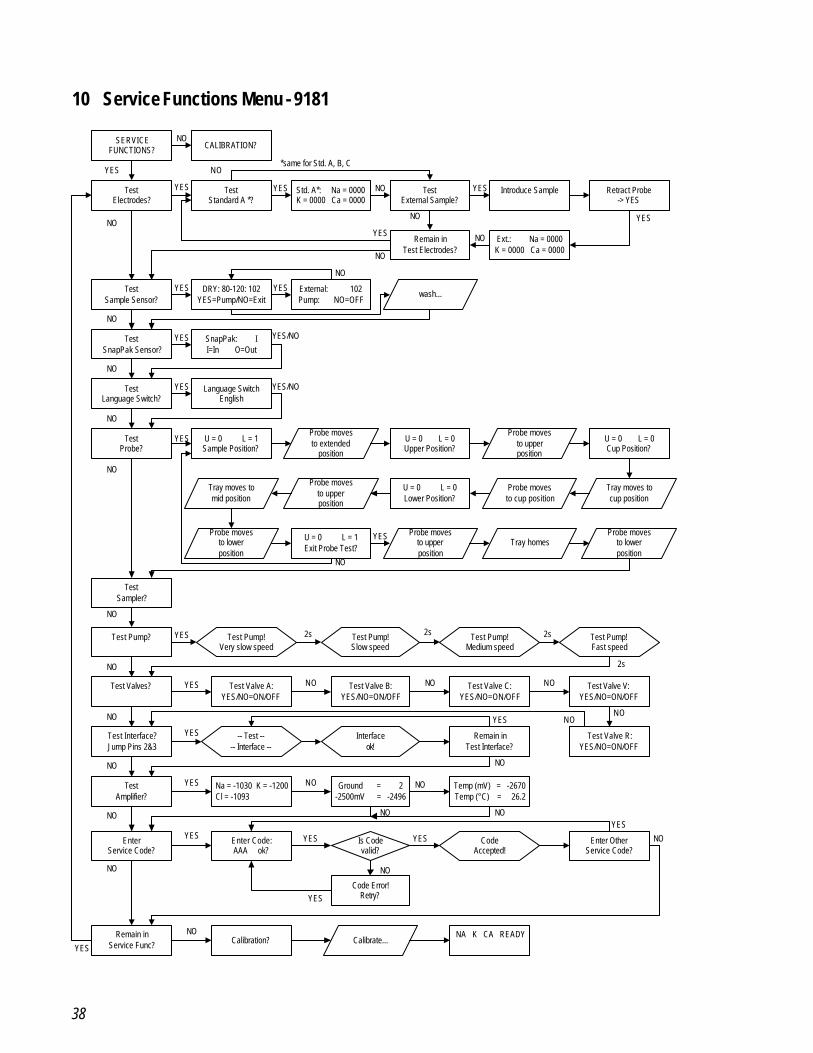
10 Service Functions Menu - 9181
Test Valve C:YES/NO=ON/OFF
SERVICEFUNCTIONS? CALIBRATION?
TestElectrodes?
TestStandard A *?
Std. A*: Na = 0000K = 0000 Ca = 0000
TestExternal Sample?
Introduce Sample Retract Probe-> YES
Ext.: Na = 0000K = 0000 Ca = 0000
Remain inTest Electrodes?
TestSample Sensor?
DRY: 80-120: 102YES=Pump/NO=Exit
External: 102Pump: NO=OFF
wash...
TestProbe?
Test Pump?
Test Valves?
Test Pump!Very slow speed
Test Pump!Slow speed
Test Pump!Medium speed
Test Pump!Fast speed
Test Valve A:YES/NO=ON/OFF
Test Valve B:YES/NO=ON/OFF
Test Valve V:YES/NO=ON/OFF
Test Interface?Jump Pins 2&3
TestAmplifier?
EnterService Code?
Na = -1030 K = -1200 Cl = -1093
Ground = 2-2500mV = -2496
Remain inTest Interface?
Enter Code:AAA ok?
Enter OtherService Code?
NA K CA READYCalibration?
Remain inService Func?
-- Test ---- Interface --
Interfaceok!
CodeAccepted!
Calibrate...
Is Codevalid?
NO
NO
NO
NO
NO
NO
NO
NO
NO
NO NO NO
NO
NONO
NO
NO
NO
NO
NO
NO
YES
YES YES YES
YES
YES
YESYES
YES
YES
YES
YES YES
YES
YESYES
YES
2s 2s 2s
2s
TestSnapPak Sensor?
TestLanguage Switch?
NO
NO
SnapPak: II=In O=Out
Language SwitchEnglish
YES
YES YES/NO
YES/NO
YESNO
NO
Test Valve R:YES/NO=ON/OFF
NO
Code Error!Retry?YES
NO
NO
Temp (mV) = -2670Temp (°C) = 26.2
NO
NO
*same for Std. A, B, C
YES
TestSampler?
Probe movesto extended
position
U = 0 L = 1Sample Position?
U = 0 L = 0Upper Position?
U = 0 L = 0Cup Position?
U = 0 L = 0Lower Position?
U = 0 L = 1Exit Probe Test?
Probe movesto upperposition
Probe movesto cup position
Tray moves tocup position
Probe movesto upperposition
Tray moves tomid position
Probe movesto lowerposition
Probe movesto upperposition
Tray homesProbe moves
to lowerposition
YES
NO
NO
39
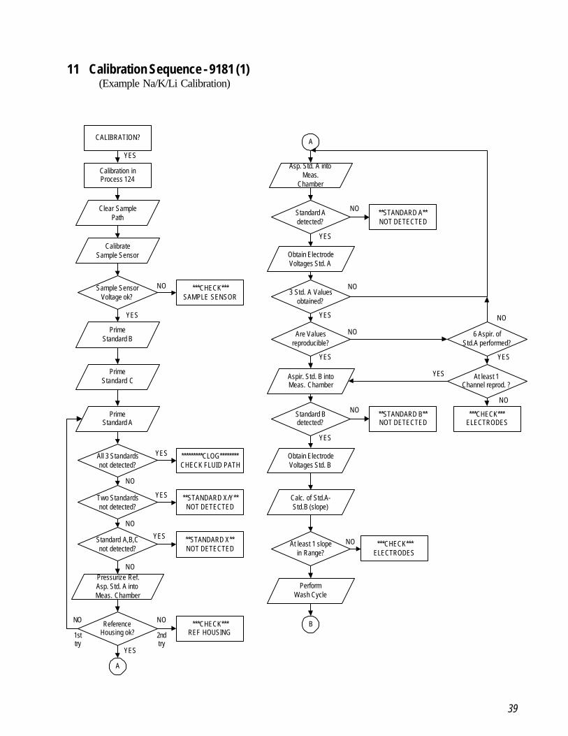
11 Calibration Sequence - 9181 (1) (Example Na/K/Li Calibration)
CALIBRATION?
Calibration inProcess 124
Clear SamplePath
CalibrateSample Sensor
Sample SensorVoltage ok?
PrimeStandard B
Two Standardsnot detected?
PrimeStandard A
All 3 Standardsnot detected?
Pressurize Ref.Asp. Std. A intoMeas. Chamber
ReferenceHousing ok?
A
***CHECK***SAMPLE SENSOR
**STANDARD X/Y**NOT DETECTED
*********CLOG********CHECK FLUID PATH
***CHECK***REF HOUSING
YES
YES
YES
YES
NO
NO
NO
NO
A
Asp. Std. A intoMeas.
Chamber
Standard Adetected?
Obtain ElectrodeVoltages Std. A
3 Std. A Valuesobtained?
Are Valuesreproducible?
Aspir. Std. B intoMeas. Chamber
Standard Bdetected?
Obtain ElectrodeVoltages Std. B
Calc. of Std.A-Std.B (slope)
**STANDARD B**NOT DETECTED
NO
**STANDARD A**NOT DETECTED
NO
***CHECK***ELECTRODES
6 Aspir. ofStd.A performed?
NO
NO
NO
NO
YES
YES
YES
YES
YES
Standard A,B,Cnot detected?
**STANDARD X**NOT DETECTED
YES
NO
PrimeStandard C
YES
NO
1sttry
2ndtry
At least 1Channel reprod. ?
NO
YES
At least 1 slopein Range?
***CHECK***ELECTRODES
PerformWash Cycle
B
40
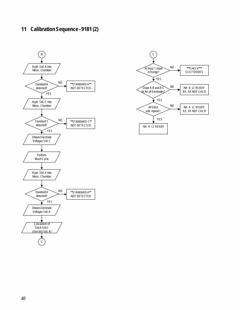
11 Calibration Sequence - 9181 (2)
Aspir. Std. A intoMeas. Chamber
Standard Adetected?
**STANDARD A**NOT DETECTED
NO
Calculation ofStd.A-Std.C
(Use last Std. A)
All Std.Avolt. reprod.?
At least 1 slopein Range?
***CHECK***ELECTRODES
NA K LI READY
NA K LI READYXX, XX NOT CAL'D
NO
YES
YES
B
Aspir. Std. C intoMeas. Chamber
Standard Cdetected?
**STANDARD C**NOT DETECTED
NO
Obtain ElectrodeVoltages Std. C
PerformWash Cycle
Aspir. Std. A intoMeas. Chamber
Standard Adetected?
**STANDARD A**NOT DETECTED
NO
Obtain ElectrodeVoltages Std. A
Slope A-B and A-Cok for all Electrodes?
NA K LI READYXX, XX NOT CAL'D
C
C
YES
YES
YES
YES
NO
NO
41
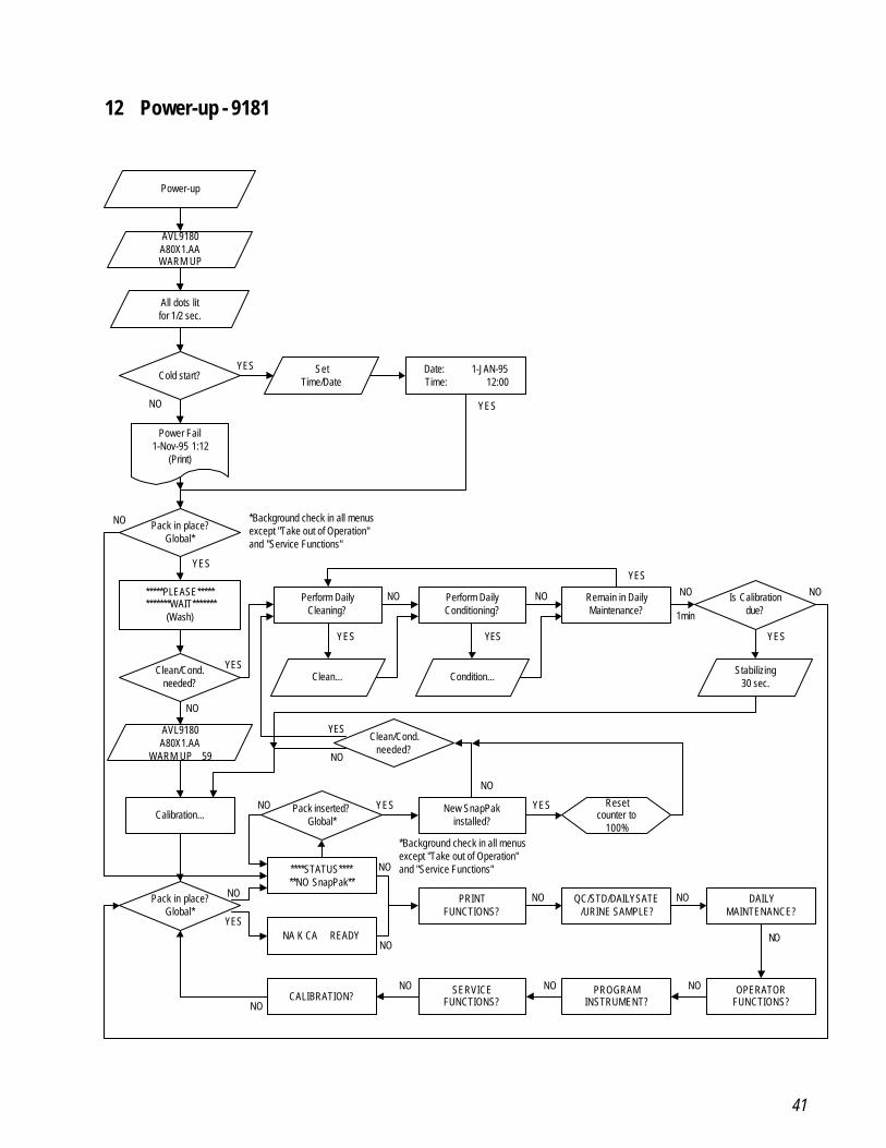
12 Power-up - 9181
Power-up
AVL9180A80X1.AAWARM UP
All dots litfor 1/2 sec.
Cold start?Set
Time/DateDate: 1-JAN-95Time: 12:00
Power Fail1-Nov-95 1:12
(Print)
Pack in place?Global*
*****PLEASE************WAIT*******
(Wash)
Perform DailyCleaning?
Perform DailyConditioning?
Is Calibrationdue?
Clean/Cond.needed?
Clean... Condition...
Remain in DailyMaintenance?
Stabilizing30 sec.
AVL9180A80X1.AA
WARM UP 59
Clean/Cond.needed?
Calibration...Pack inserted?
Global*New SnapPak
installed?
Resetcounter to
100%
Pack in place?Global*
****STATUS******NO SnapPak**
NA K CA READY
PRINTFUNCTIONS?
QC/STD/DAILYSATE/URINE SAMPLE?
DAILYMAINTENANCE?
CALIBRATION?SERVICE
FUNCTIONS?PROGRAM
INSTRUMENT?OPERATOR
FUNCTIONS?
YES
YESNO
NO
YES
YES
YES YES
NO NO
YES
NO
1min
YES
NO
YES
NO
NO YES YES
NO
YES
NO
NO
NO
NO
NO NO
NO
NO
NO
NO
*Background check in all menusexcept "Take out of Operation"and "Service Functions"
*Background check in all menusexcept "Take out of Operation"and "Service Functions"
NO
42
3.4 Service Functions
The Service Functions mode provides a menu of service test functions to assist infailure diagnosis and identification. A logic flow chart is provided for reference ofthe sequences included in the Service Functions mode.
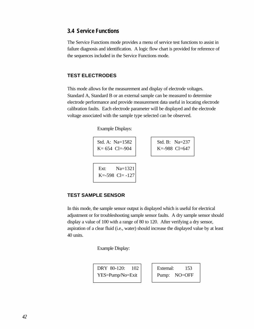
TEST ELECTRODES
This mode allows for the measurement and display of electrode voltages.Standard A, Standard B or an external sample can be measured to determineelectrode performance and provide measurement data useful in locating electrodecalibration faults. Each electrode parameter will be displayed and the electrodevoltage associated with the sample type selected can be observed.
Example Displays:
Std. A: Na=1582 Std. B: Na=237K= 654 Cl=-904 K=-988 Cl=647
Ext: Na=1321 K=-598 Cl= -127
TEST SAMPLE SENSOR
In this mode, the sample sensor output is displayed which is useful for electricaladjustment or for troubleshooting sample sensor faults. A dry sample sensor shoulddisplay a value of 100 with a range of 80 to 120. After verifying a dry sensor,aspiration of a clear fluid (i.e., water) should increase the displayed value by at least40 units.
Example Display:
DRY 80-120: 102 External: 153YES=Pump/No=Exit Pump: NO=OFF
43
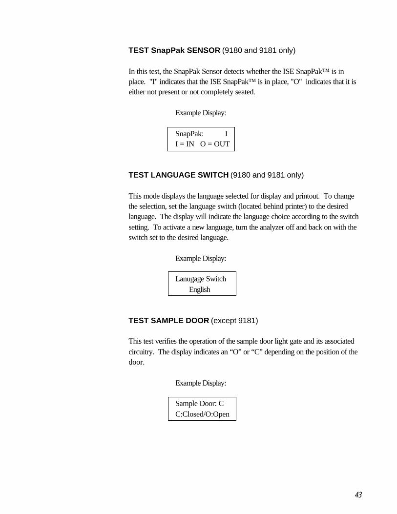
TEST SnapPak SENSOR (9180 and 9181 only)
In this test, the SnapPak Sensor detects whether the ISE SnapPak™ is inplace. "I" indicates that the ISE SnapPak™ is in place, "O" indicates that it iseither not present or not completely seated.
Example Display:
SnapPak: II = IN O = OUT
TEST LANGUAGE SWITCH (9180 and 9181 only)
This mode displays the language selected for display and printout. To changethe selection, set the language switch (located behind printer) to the desiredlanguage. The display will indicate the language choice according to the switchsetting. To activate a new language, turn the analyzer off and back on with theswitch set to the desired language.
Example Display:
Lanugage Switch English
TEST SAMPLE DOOR (except 9181)
This test verifies the operation of the sample door light gate and its associatedcircuitry. The display indicates an “O” or “C” depending on the position of thedoor.
Example Display:
Sample Door: CC:Closed/O:Open
44
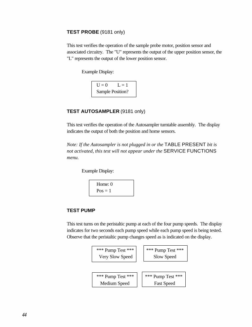
TEST PROBE (9181 only)
This test verifies the operation of the sample probe motor, position sensor andassociated circuitry. The "U" represents the output of the upper position sensor, the"L" represents the output of the lower position sensor.
Example Display:
U = 0 L = 1Sample Position?
TEST AUTOSAMPLER (9181 only)
This test verifies the operation of the Autosampler turntable assembly. The displayindicates the output of both the position and home sensors.
Note: If the Autosampler is not plugged in or the TABLE PRESENT bit isnot activated, this test will not appear under the SERVICE FUNCTIONSmenu.
Example Display:
Home: 0Pos = 1
TEST PUMP
This test turns on the peristaltic pump at each of the four pump speeds. The displayindicates for two seconds each pump speed while each pump speed is being tested.Observe that the peristaltic pump changes speed as is indicated on the display.
*** Pump Test *** *** Pump Test *** Very Slow Speed Slow Speed
*** Pump Test *** *** Pump Test *** Medium Speed Fast Speed
45
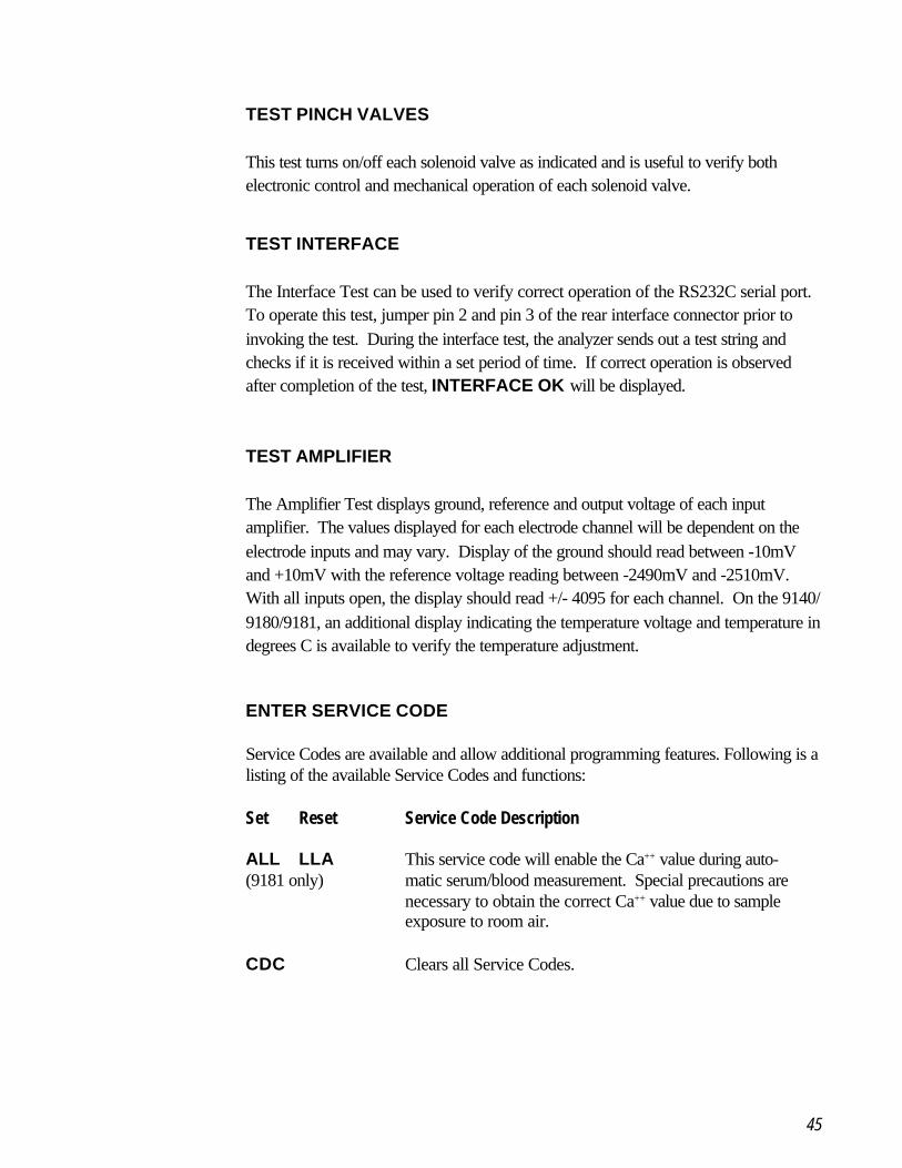
TEST PINCH VALVES
This test turns on/off each solenoid valve as indicated and is useful to verify bothelectronic control and mechanical operation of each solenoid valve.
TEST INTERFACE
The Interface Test can be used to verify correct operation of the RS232C serial port.To operate this test, jumper pin 2 and pin 3 of the rear interface connector prior toinvoking the test. During the interface test, the analyzer sends out a test string andchecks if it is received within a set period of time. If correct operation is observedafter completion of the test, INTERFACE OK will be displayed.
TEST AMPLIFIER
The Amplifier Test displays ground, reference and output voltage of each inputamplifier. The values displayed for each electrode channel will be dependent on theelectrode inputs and may vary. Display of the ground should read between -10mVand +10mV with the reference voltage reading between -2490mV and -2510mV.With all inputs open, the display should read +/- 4095 for each channel. On the 9140/9180/9181, an additional display indicating the temperature voltage and temperature indegrees C is available to verify the temperature adjustment.
ENTER SERVICE CODE
Service Codes are available and allow additional programming features. Following is alisting of the available Service Codes and functions:
Set Reset Service Code Description
ALL LLA This service code will enable the Ca++ value during auto-(9181 only) matic serum/blood measurement. Special precautions are
necessary to obtain the correct Ca++ value due to sampleexposure to room air.
CDC Clears all Service Codes.
46
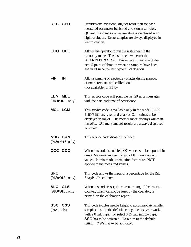
DEC CED Provides one additional digit of resolution for eachmeasured parameter for blood and serum samples.QC and Standard samples are always displayed withhigh resolution. Urine samples are always displayed inlow resolution.
ECO OCE Allows the operator to run the instrument in theeconomy mode. The instrument will enter theSTANDBY MODE. This occurs at the time of thenext 2-point calibration when no samples have beenanalyzed since the last 2-point calibration.
FIF IFI Allows printing of electrode voltages during printoutof measurements and calibrations.(not available for 9140)
LEM MEL This service code will print the last 20 error messages(9180/9181 only) with the date and time of occurrence.
MGL LGM This service code is available only in the model 9140/9180/9181 analyzer and enables Ca++ values to bedisplayed in mg/dL. The normal mode displays values inmmol/L. QC and Standard results are always displayedin mmol/L.
NOB BON This service code disables the beep.(9180 /9181only)
QCC CCQ When this code is enabled, QC values will be reported indirect ISE measurement instead of flame-equivalentvalues. In this mode, correlation factors are NOTapplied to the measured values.
SFC This code allows the input of a percentage for the ISE(9180/9181 only) SnapPakTM counter.
SLC CLS When this code is set, the current setting of the leasing(9180/9181 only) counter, which cannot be reset by the operator, is
printed on the calibration report.
SSC CSS This code toggles needle height to accommodate smaller(9181 only) sample cups. In the default setting, the analyzer works
with 2.0 mL cups. To select 0.25 mL sample cups,SSC has to be activated. To return to the defaultsetting, CSS has to be activated.
47
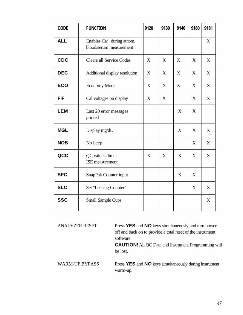
CODE FUNCTION 9120 9130 9140 9180 9181
ALL Enables Ca++ during autom. Xblood/serum measurement
CDC Clears all Service Codes X X X X X
DEC Additional display resolution X X X X X
ECO Economy Mode X X X X X
FIF Cal voltages on display X X X X
LEM Last 20 error messages X Xprinted
MGL Display mg/dL X X X
NOB No beep X X
QCC QC values direct X X X X XISE measurement
SFC SnapPak Counter input X X
SLC Set "Leasing Counter" X X
SSC Small Sample Cups X
ANALYZER RESET Press YES and NO keys simultaneously and turn poweroff and back on to provide a total reset of the instrumentsoftware.CAUTION! All QC Data and Instrument Programming willbe lost.
WARM-UP BYPASS Press YES and NO keys simultaneously during instrumentwarm-up.
48
4 Description of Modules
4.1 Mechanical Assemblies
4.1.1 Front Door Assembly
For the 9120, 30, 40 and 80 analyzers, the front door can be removed by movingthe analyzer to the edge of a work surface so the analyzer door, when opened, willextend past the edge of the work surface. With one hand, hold the analyzer doornear the right side hinge pin and, with the other hand, gently apply pressure to themiddle rear area of the door. This will allow the right hinge pin to clear the retaininghole in the main chassis. The door can then be removed from the analyzer.The 9181 front panel can be removed by tilting it slightly away from the analyzerand lifting it straight up. The plastic window can also be replaced in the field bygently pressing from the rear of the window and snapping the plastic window outtoward the front of the analyzer door. The door magnets cannot be replaced in thefield as they are glued in place with conductive adhesive.
4.1.2 Needle Unit Assembly
Both sample needle and fill port are designed for easy replacement by the user.To remove the fill port assembly for replacement, pull the fill port holder towardsthe front for easy access. Then, press the two plastic tabs on the fill port to allowremoval of the fill port from the fill port holder. The sample needle can also beremoved and is supplied as a one-piece assembly including the intake tubing.To remove the sample needle, grasp the needle near the white holder block and pullup to unsnap the sample needle from its position. To replace the assembly, align areplacement sample needle and press the replacement assembly into place.
Three screws located on the left side of the assembly hold the needle unit assemblyin place. To access the two rear screws, turn power off and remove the rear panel.The rear panel can be moved away from the unit for easier access by unplugging thewire harness from the power supply. The SBC board can now be removed byremoving the screws which secure the SBC board and disconnecting the cables onthe SBC board. Disconnect the connector to the lamp board which supplies theDoor Open signal. The two rear screws which secure the needle unit can now beremoved using an Allen wrench. Then, remove the front securing screw, the sampleintake tubing and the reagent supply tubing (red tag) from the fill port. The needleunit can now be removed from the front of the analyzer for replacement. Referencethe Illustrated Parts diagram in Section 8 for a detailed parts diagram of the needleunit.
49
4.1.3 Electrode Holder Assembly
To remove the electrode holder assembly from the analyzer, first unplug thesample intake tubing on the right side of the module, then the sample sensorcable, then remove the reference solution tubing connector and last, take out thewaste tube (green tag) at the left side of the electrode holder. The electrodeholder can now be removed by pressing the two plastic tabs (right and left sideof the module) and sliding the module forward. Press the plastic tabs again torelease the second detent and completely remove the module from the analyzer.The sample sensor and/or the left side electrode holder can be removed andreplaced by removing the screws on the under side of this module. The Illus-trated Parts List in Section 8 provides a detailed reference of the parts of thisassembly.
4.1.4 Peristaltic Pump Assembly
Replacement of the roller assembly of the peristaltic pump can be accomplishedby removing the pump tubing and firmly pulling the roller assembly toward thefront. To replace the roller assembly, align the roller and the flat on the motorshaft and press the replacement roller into position.
To remove the motor, first remove the rear panel assembly and SBC Board asdescribed in Sections 4.1.7 and 4.1.8. Now, the electrical connector on thelamp board can be accessed to unplug the motor connector. The motor cannow be removed by removing four screws located on the front of the housingnear the peristaltic pump.
4.1.5 Solenoid Assembly
Removal of each solenoid is identical. Each solenoid valve has a removablepressure piece which is held in place by a solenoid cap. To remove the pres-sure piece, locate the arrow on the solenoid cap and remove the solenoid capby sliding it off the solenoid shaft in the direction of the arrow. This exposes thepressure piece which can now be removed from the solenoid shaft. To replacepressure piece and cap, energize the solenoid as described in Section 3.2 (TestValves). This extends the solenoid shaft to the outermost position for ease inreplacing pressure piece and cap. Removal of the pressure piece and cap isrequired prior to removing the solenoid and allows for easier replacement of thetubing under each solenoid.
50
To remove the solenoid assembly, the rear panel and the SBC Board described inSection 4.1.8 must be removed first. Each solenoid has an electrical connection tothe lamp board which must be unplugged prior to removal of the solenoid. At thispoint, remove the two screws on the front panel to remove the solenoid assembly.
4.1.6 Printer Assembly
The printer assembly is designed to allow for easy removal by the user which can beaccomplished without removal of the electrical power to the analyzer. Slide thepaper tray forward to allow access to the printer, tear the paper roll and completelyremove it together with the paper tray. Slide fingers under the printer assembly andpull the printer forward. This will disengage the printer from the interconnector andenable removal of the assembly from the front of the analyzer. Removal of theprinter should be performed for replacement and for removal of a paper jam.To replace the printer, locate the printer slide and insert the printer assembly. Pressfirmly into place to ensure electrical connection of the printer.
Note: Never attempt to dislodge paper from the printer with a paper clip orsimilar object to avoid damage to the print head or printer platen.
4.1.7 Rear Panel Assembly
To remove the rear panel assembly, ensure that the power cord has been discon-nected. Remove the four corner screws to expose the rear panel. The powersupply module located on the rear panel assembly can now be removed by remov-ing the three screws securing the circuit board and by disconnecting the wiringinterconnections. The main power receptacle can also be replaced by removing thetwo screws holding this assembly.
4.1.8 SBC Board
After the rear panel (Section 4.1.7) has been removed, the SBC Board is acces-sible for removal. This circuit board can be removed by removing the sevenscrews securing the board to the housing and by disconnecting electrical connectorsfrom the power supply module, display board and lamp board.The electrode push pins can now be replaced by simply pulling the connecting pinfrom its socket. When installing the board, make sure to place the plastic washersunder the screw heads.
51
4.1.9 Lamp Board
The rear panel and SBC board must be removed to gain access to the lampboard. Remove one screw and washer which hold the board in place andremove the electrical connectors to remove this board.
4.1.10 Display Board
The rear panel and SBC board must be removed to gain access to the displayboard. Remove three screws and 50 degree spacers and unplug the samplesensor cable from the front and the ribbon cable to the SBC board to removethe display board.
52
4.2 Fluidic Module
4.2.1 Standard A
Standard A is drawn to the electrode module by vacuum provided by the peristalticpump. When Standard A is to be aspirated into the electrode module, solenoidvalve A is opened and solenoid valves B, V and R are closed. Standard A is thendrawn from the ISE SnapPakTM, to the fill port, through the sample needle and issensed by the sample sensor. At this point, solenoid valve V is opened and sole-noid valve A is closed as the peristaltic pump continues to pump Standard A intothe electrode module. As the trailing edge of the Standard A sample is sensed bythe sample sensor, the peristaltic pump stops. During the time Standard A isaspirated into the electrode module, the reference housing is pressurized due to theperistaltic pump providing pressure to the reference solution line and solenoid valveR being closed. An amount of reference solution is forced out through the referencejunction to provide contact to the sample.
4.2.2 Standard B/C
The process for Standard B/C is identical to that of Standard A with the exceptionof the operation of solenoid valves B and C. These solenoid valves are operated inreverse order of Standard A aspiration.
4.2.3 Reference Solution
The reference housing is filled automatically using the second winding of theperistaltic pump and solenoid valve R. The reference solution connector allows forthe reference housing tubing to be plugged into the reference solution circuit. As theperistaltic pump aspirates reference solution, solenoid valve R is opened to allowexcess solution to be pumped into the reference return line of the ISE SnapPakTM.
4.2.4 Waste Liquids
Calibration standard and sample waste are pumped out of the left side of theelectrode module (green-banded tubing) through the peristaltic pump to the wasteline of the ISE SnapPakTM. An internal one-way valve is incorporated into thewaste line of each ISE SnapPakTM to prevent any waste products from leakingout of the ISE SnapPakTM.
53
4.2.5 Main Tube Set
The main tube set is supplied as a pre-cut tubing harness with the fluidic inter-connections preassembled. Replacement of the tube set should be performedannually. For removal of the tubing, first remove the ISE SnapPakTM from thereagent compartment. This will allow access for removal of the white TPRblock which is the main interconnection between the ISE SnapPakTM and thetubing. This block can be removed by grasping the front surface and pullingforward. Next, remove tubing from each solenoid valve. Follow the procedureoutlined in Section 4.1.5 for disassembly of the solenoid valves to enable fluidictubing to be easily removed at each solenoid. Pull the two pump windings at theperistaltic pump tube set off the pump roller and remove the white referencesolution tube connector. Remove the white TPR reference solution block bygrasping the front of the block and pulling forward. The three tube connectionsare labeled with green, blue and red tags. All remaining tubes can now beremoved and the entire tubing harness can be discarded.
Fit the replacement tubing harness and assemble in reverse order as disassem-bly. Reference the Tube Diagram on the next page for correct tube locations.
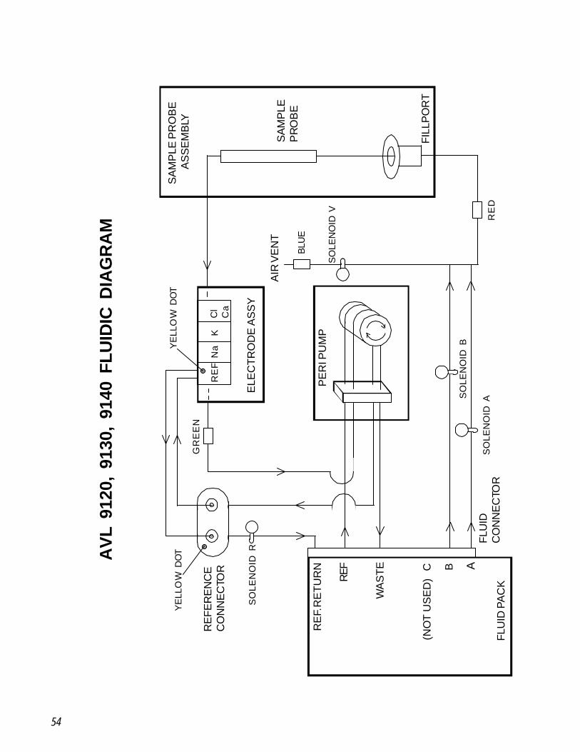
54
AB
FLU
ID P
AC
K
RE
F. R
ET
UR
N
REF
WA
STE
(NO
T U
SE
D)
C
FLU
IDC
ON
NE
CTO
R
PE
RI P
UM
P
FILL
PO
RT
SA
MP
LEP
RO
BE
SA
MP
LE P
RO
BE
A
SS
EM
BLY
AIR
VE
NT
ELE
CTR
OD
E A
SS
Y
RE
FER
EN
CE
CO
NN
EC
TOR
SO
LEN
OID
R
GR
EE
N
RE
FN
aK
Cl
Ca
BLU
E
SO
LEN
OID
V
SO
LEN
OID
A
SO
LEN
OID
B
RE
D
YE
LLO
W D
OT
YE
LLO
W D
OTAV
L 91
20,
9130
, 91
40 F
LUID
IC D
IAG
RA
M
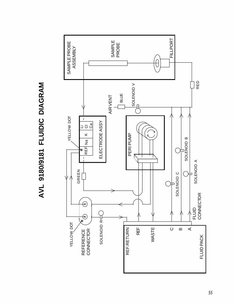
55
B
FLU
ID P
AC
K
RE
F. R
ET
UR
N
REF
WA
STE
FLU
IDC
ON
NE
CTO
R
PE
RI P
UM
P
FILL
PO
RT
SA
MP
LEP
RO
BE
SA
MP
LE P
RO
BE
A
SS
EM
BLY
AIR
VE
NT
ELE
CTR
OD
E A
SS
Y
RE
FER
EN
CE
CO
NN
EC
TOR
SO
LEN
OID
R
GR
EE
N
RE
FN
aK
BLU
E
SO
LEN
OID
V
SO
LEN
OID
A
SO
LEN
OID
B
RE
D
YE
LLO
W D
OT
YE
LLO
W D
OT
SO
LEN
OID
CC A
Li Cl
Ca
AV
L 91
80/9
181
FLU
IDIC
DIA
GR
AM
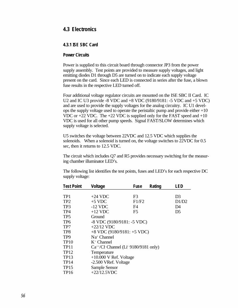
56
4.3 Electronics
4.3.1 ISE SBC Card
Power Circuits
Power is supplied to this circuit board through connector JP3 from the powersupply assembly. Test points are provided to measure supply voltages, and lightemitting diodes D1 through D5 are turned on to indicate each supply voltagepresent on the card. Since each LED is connected in series after the fuse, a blownfuse results in the respective LED turned off.
Four additional voltage regulator circuits are mounted on the ISE SBC II Card. ICU2 and IC U3 provide -8 VDC and +8 VDC (9180/9181: -5 VDC and +5 VDC)and are used to provide the supply voltages for the analog circuitry. IC U1 devel-ops the supply voltage used to operate the peristaltic pump and provide either +10VDC or +22 VDC. The +22 VDC is supplied only for the FAST speed and +10VDC is used for all other pump speeds. Signal FAST/SLOW determines whichsupply voltage is selected.
U5 switches the voltage between 22VDC and 12.5 VDC which supplies thesolenoids. When a solenoid is turned on, the voltage switches to 22VDC for 0.5sec, then it returns to 12.5 VDC.
The circuit which includes Q7 and R5 provides necessary switching for the measur-ing chamber illuminator LED’s.
The following list identifies the test points, fuses and LED’s for each respective DCsupply voltage:
Test Point Voltage Fuse Rating LED
TP1 +24 VDC F3 D3TP2 +5 VDC F1/F2 D1/D2TP3 -12 VDC F4 D4TP4 +12 VDC F5 D5TP5 GroundTP6 -8 VDC (9180/9181: -5 VDC)TP7 +22/12 VDCTP8 +8 VDC (9180/9181: +5 VDC)TP9 Na+ ChannelTP10 K+ ChannelTP11 Ca++/Cl- Channel (Li+ 9180/9181 only)TP12 TemperatureTP13 +10.000 V Ref. VoltageTP14 -2.500 VRef. VoltageTP15 Sample SensorTP16 +22/12.5VDC
57
Valve Drivers
The solenoids are activated by transistors Q9 - Q13. To open the solenoid, a0.5-second pulse of 22 volts is applied, then the voltage drops down to 12.5volts to hold the solenoid open.
Pump Motor Driver/Cover Sensor
The pump driver circuit IC U9 and IC U10 provide the drive and control forthe peristaltic pump. Signals PUMPEN, Pump Enable and PUMPSTEP, PumpStep Pulses enable IC U10 to provide the necessary control to driver IC U9which supplies pump drive signals PHASE A through PHASE D to controlperistaltic pump operation.
IC U11 operates with signal DCLOSED from the sample door light gate toprovide signal DOOR which detects the status of the sample door (open orclosed).
Input Amplifiers
IC U13, U14 and U15 (9180/9181: U13 only) provide high to low inputimpedance matching for each Electrode input. Offset generator IC U12D andamplifiers IC U12A, U12B and U12C provide the necessary gain and offset foreach electrode channel. TP9, TP10 and TP11 provide test points for the Na+,K+ and Cl-/Ca++/Li channels respectively.
Temperature Sensor
This is an optional circuit which is used in the 9140, 9180 and 9181.The circuit creates a temperature-dependent voltage which is converted bysoftware to degrees C. R54 can be adjusted for correct temperature setting.
Analog Channel Selector and A/D Converter
Analog inputs from the input amplifiers are selected via signals ADSEL0 throughADSEL2 and are multiplexed by IC U19. This multiplexed signal is then fed tothe A/D Converter IC U20. IC U21 supplies the necessary reference voltage(2500mV) for the A/D Converter and can be measured at TP14.
58
Microprocessor
Microprocessor IC U31, EPROM IC U25 (9180/9181: U40) and MOSTEK RealTime Clock/RAM IC U22 form the components of the central processing system.IC U23 Address Demultiplexer, IC U24 Programmable Array Logic (PAL) and ICU28 provide serial data buses (9180/9181: U23, U24 and U28 not present). ICU34 through IC U38 convert serial data to parallel data and provide printer data,display data, solenoid valve control and peristaltic pump control. This fashion ofserial to parallel data conversion is used to prevent analyzer lock-up by peripheraldevices. The RS232 serial interface is a direct input/output from the microproces-sor utilizing interface driver and receiver U29 and U30.
SnapPak Sensor (9180/9181 only)
Optical detector ISO1 provides a signal indicating if the ISE SnapPak™ is in place.This signal is fed to U41 which converts the light gate input to a digital logic outputindicating SnapPak position (IN or OUT).
4.3.2 Lamp Board
The lamp board contains the LED array used to illuminate the measuring chamberand the interconnectors used for all solenoids, the peristaltic pump, door sensor andsample turntable (9181 only). A ribbon cable from the SBC Board supplies theelectrical connection for each signal through connector JP6.
4.3.3 Display Board
The display board contains the LCD display, sample sensor connector and theYES and NO switches used for operation of the analyzer. Power and signalinterconnection is accomplished via a ribbon cable from the SBC board throughJP2 on the display board.
Display boards utilized in the 9181 analyzer also contain circuitry for both theneedle mechanism motor control and position sensor. The autosampler "TablePresent" signal is also buffered through U1 on this board.
59
5 Maintenance and Troubleshooting
Maintenance procedures for the 9120, 30, 40, 80, 81 Analyzers require minimaltime by the operator to perform. The procedures outlined below should beperformed by the schedule indicated. Detailed instructions for these procedures canbe found in the Operator's Manual describing the correct method to perform routineanalyzer maintenance.
5.1 Maintenance
Daily Maintenance
- Perform cleaning cycle.
- Perform conditioning cycle.
Weekly Maintenance
- Clean sample probe and fill port.
- Clean analyzer surfaces.
Monthly Maintenance
- Clean reference electrode housing.
Six Month Maintenance
- Replace peristaltic pump tubing.
Annual Preventive Maintenance
- Replace complete tubing set.
- Replace peristaltic pump tubing.
- Replace fill port assembly.
- Replace sample probe.
- Replace sample sensor Quad-ring.
- Check sample sensor voltage.
- Check sample temperature (9140/80/81 only).
60
5.2 Error Messages and Troubleshooting
STATUS: NOT CALIBRATED
This message is only displayed when a calibration has been interrupted bypressing NO or opening the sample door. Perform a calibration to return to theREADY Mode.
STANDARD A NOT DETECTED
This message is displayed when the sample sensor is unable to properly detectthe Standard A solution in a programmed time period. As the analyzer draws asample of Standard A, the leading edge of the solution is detected by thesample sensor. The sample sensor must also detect a continuous flow ofStandard A Solution into the sample chamber, lasting several seconds, withoutencountering air bubbles or air. After several seconds, the trailing edge of theStandard A sample is sensed, the peristaltic pump stops and measurementoccurs.
Possible causes and remedies:
• Check for air leaks preventing the Standard from being drawn into thechamber. Ensure that all O-rings are in place. There must be acontinuous draw of standard solution, free of air bubbles. Check solenoid V for proper sealing of the vent line. Check fill port to ensure the absence of air leaks.
• Check for clots or crystals formed in the Standard A tubing orelectrode chamber.
• Ensure that the sample sensor is plugged in securely and performSample Sensor Test to ensure sensor is operating correctly. Clean,adjust or replace sample sensor to correct sample sensor operation.
• Replace peristaltic pump tube set to ensure proper sample aspiration.
• Check the fluid remaining in the ISE SnapPakTM. If less than 5%remains, replace the ISE SnapPakTM.

61
STANDARD B NOT DETECTEDSTANDARD C NOT DETECTED (9180/9181 only)
The system for drawing Standard B or C is like that of Standard A. If Standard Ais drawn properly and Standard B or C is not detected, check Standard B tubingfor crystallization. Perform checks for Standard A detection problems to correct.During the calibration sequence, Standard B or C is drawn into the measuringchamber prior to Standard A, therefore check if Standard A calibrant can beproperly detected to isolate possible fluidic faults. If neither Standard A, B nor Care detected check for air leaks or blockages within the fluidic path.
CHECK SAMPLE SENSOR
The sample sensor must provide a reading of 80 - 120 when air is detected.Perform Test Sample Sensor to observe sample sensor response. When clear fluid(e.g. water) is aspirated, the sample sensor display must indicate an increase of of atleast 40 units. For blood samples (not transparent), the reading should decrease byat least 40 units. The sample sensor is calibrated with air during each calibration.Perform a calibration to remove the error message after troubleshooting.
Possible causes and remedies:
• Clean sample sensor using Daily Cleaning procedure.
• Check for correct drying of measuring chamber during the wash cycle.
• Replace peristaltic pump tube set.
• Test and adjust sample sensor to correct adjustment.
• Replace sample sensor assembly.
62
CHECK REFERENCE HOUSING
At the beginning of a calibration, pressure is formed in the reference housingwhile the R valve is closed and the V valve is open. After Standard A isdetected in the sample chamber, the back pressure formed in the referencehousing causes the Standard A solution to move back toward the samplesensor. When the standard A solution is detected by the sample sensor, the Rvalve is opened to release the pressure. If the sample sensor does not detectstandard A as it moves back, CHECK REFERENCE HOUSING will bedisplayed.
Possible causes and remedies:
• Check for clogged reference housing and clean per monthlymaintenance procedures.
• Check and ensure that reference tubing is securely connected at thetubing connector.
• Check for proper filling of the reference housing and ensure thatreference solution reagent level allows complete filling of thereference housing.
• Check for bubble-free aspiration of Standard A.
PLEASE CLOSE SAMPLE DOOR (except 9181)
This message occurs and prints NO SAMPLE on the print-out, when either oftwo conditions exists.
1. Sample door is not closed within 20 seconds after samples are inplace.
2. Sample door has been opened and no sample is detected within 20seconds.
Possible causes and remedies:
• Close sample door within the time allowed.
• Check needle mechanism light gate.
• Check whether sample sensor is plugged in.
63
NO SAMPLE
This message is displayed when any of the following conditions occur:
1. During sampling, either a bubble in the sample is detected or thesample sizeis smaller than the minimum sample required.
2. The sample door is opened and no sample is fed into the analyzer.
3. Sample door is not closed within 20 seconds after sample is detected.
Possible causes and remedies:
• Check whether the sample sensor is plugged in and performTEST SAMPLE SENSOR to verify that it operates correctly.
• Check sample draw and look for clots or leaks in the sampling system.
CLEANING FLUID NOT DETECTED
When the cleaning cycle has been initiated, the analyzer checks for properaspiration of the cleaning solution using the sample sensor. If solution is notdetected in the proper time, above error message will be displayed.
Possible causes and remedies:
• Ensure that a sufficient volume of cleaning solution is presented foraspiration and no air bubbles are present as solution is aspirated.
• Check to ensure that the solution is being aspirated through the samplingmechanism correctly. The sample path must be free of leaks or clots.
• Verify that sample sensor is properly plugged in and perform theSAMPLE SENSOR TEST to verify the correct operation of thesample sensor.
• Check pump tubing and replace as necessary to ensure a correct pumprate.
64
CONDITIONING FLUID NOT DETECTED
When the conditioning cycle has been initiated, the analyzer checks for properaspiration of the conditioning solution using the sample sensor. If the solution isnot detected in the proper time, this error message will be displayed.
Possible causes and remedies:
• Ensure that a sufficient volume of conditioning solution is presented foraspiration and no air bubbles are present as solution is aspirated.
• Check to ensure that the solution is being properly aspiratedthrough the sampling mechanism. The sample path must be free ofleaks or clots.
• Verify that sample sensor is correctly plugged in and perform theSAMPLE SENSOR TEST to verify its proper operation.
• Check pump tubing and replace as necessary to ensure correctpump rate.
INTERFACE ERROR
This message is displayed only during the INTERFACE TEST. Pins 2 and 3must be shorted together to perform the INTERFACE TEST. Make surethat the pins are not shorted to chassis ground.
Possible cause and remedy:
• Replace SBC Card.
PAPER JAM OR PRINTER DEFECT
This message is displayed when the printer head is jammed and tries to print. Itis a temporary message that is displayed for 2 seconds and then sample resultsare displayed. To clear paper jam remove printer from the analyzer andremove jammed paper. Replace printer and retry. The printer can be removedby grasping the rear edge of the printer assembly and pulling it to the front. Theprinter can be removed with the Analyzer power on. To free up jammed paper,turn the small gears on the left side of the printer module.
65
CHECK ELECTRODES
This message is displayed when either of the following conditions are present.
1. More than six aspirations of Standard A are required for all electrodechannels.
2. The difference between voltage A and B is out of specification for allchannels.
Possible causes and remedies:
• Electrodes are not plugged in. Check the slide mechanism to ensure it is inthe correct position and firmly pushed into electrode connectors.
• Perform Daily Maintenance.
• Check or replace reference electrode.
• Replace ISE SnapPakTM.
NA NOT CAL’DK NOT CAL’DCL NOT CAL’DCA NOT CAL’DLI NOT CAL’D
These messages will be displayed when a specific electrode does not calibrateproperly during a calibration sequence. If more than six standard draws arerequired or the difference between Standard A and Standard B voltages is out ofrange, the NOT CALIBRATED message will be displayed for each channelwhich exhibits either of these conditions. A copy of the calibration report should beprinted to provide the electrode output voltages measured during calibration.The electrode voltage range table identifies correct voltage ranges for eachelectrode parameter.If the difference between Standard A and Standard C (9180/9181 only) is out ofrange for Li+ or Na+, LI NOT CAL’D will be displayed.Possible causes and remedies:
• Check to ensure calibration reagents are transported correctly. Test forleaks, blockages, bubbles, or improper pump flow rate.
• Check or replace ISE SnapPakTM.
• Check whether electrodes are plugged in properly. Check the slidemechanism to ensure it is in the correct position and firmly pushed intoelectrode connectors. Clean and/or replace electrode.
• If A-C is out of range for Na+, repeat the calibration or replace theISE SnapPakTM.
• Check or replace SBC Card.
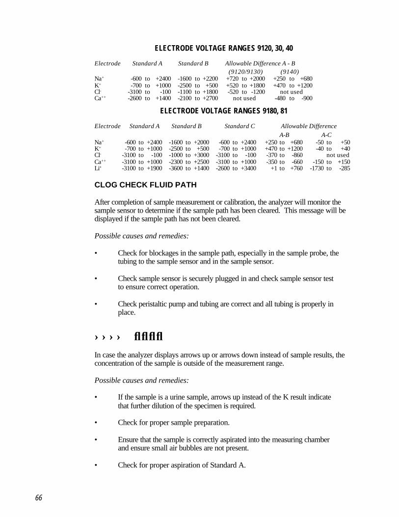
66
ELECTRODE VOLTAGE RANGES 9120, 30, 40
Electrode Standard A Standard B Allowable Difference A - B (9120/9130) (9140)
Na+ -600 to +2400 -1600 to +2200 +720 to +2000 +250 to +680K+ -700 to +1000 -2500 to +500 +520 to +1800 +470 to +1200Cl- -3100 to -100 -1100 to +1800 -520 to -1200 not usedCa++ -2600 to +1400 -2100 to +2700 not used -480 to -900
ELECTRODE VOLTAGE RANGES 9180, 81
Electrode Standard A Standard B Standard C Allowable Difference A-B A-C
Na+ -600 to +2400 -1600 to +2000 -600 to +2400 +250 to +680 -50 to +50K+ -700 to +1000 -2500 to +500 -700 to +1000 +470 to +1200 -40 to +40Cl- -3100 to -100 -1000 to +3000 -3100 to -100 -370 to -860 not usedCa++ -3100 to +1000 -2300 to +2500 -3100 to +1000 -350 to -660 -150 to +150Li+ -3100 to +1900 -3600 to +1400 -2600 to +3400 +1 to +760 -1730 to -285
CLOG CHECK FLUID PATH
After completion of sample measurement or calibration, the analyzer will monitor thesample sensor to determine if the sample path has been cleared. This message will bedisplayed if the sample path has not been cleared.
Possible causes and remedies:
• Check for blockages in the sample path, especially in the sample probe, thetubing to the sample sensor and in the sample sensor.
• Check sample sensor is securely plugged in and check sample sensor testto ensure correct operation.
• Check peristaltic pump and tubing are correct and all tubing is properly inplace.
↑↑↑↑ ↓↓↓↓In case the analyzer displays arrows up or arrows down instead of sample results, theconcentration of the sample is outside of the measurement range.
Possible causes and remedies:
• If the sample is a urine sample, arrows up instead of the K result indicatethat further dilution of the specimen is required.
• Check for proper sample preparation.
• Ensure that the sample is correctly aspirated into the measuring chamberand ensure small air bubbles are not present.
• Check for proper aspiration of Standard A.
67
↑ ↓
On the 9140, 9180 and 9181 models, the calibration report will print an arrow upor down instead of the actual temperature, if the temperature measured is out ofrange (10.0°C -40.0°C). The temperature sensor is located in the right sideelectrode holder.
Possible causes and remedies:
• Ensure that sample sensor cable is securely plugged in.
• Check whether room temperature is within specified limits(15°C to 32°C / 60°F to 90°F).
• Perform temperature adjustment procedure.
• Replace SBC board or right side electrode holder.
ERR
The analyzer will display ERR in place of sample results when the analyzer isunable to obtain valid voltage readings from the electrode (A/D over- or under-flow).
Possible causes and remedies:
• Ensure that the electrodes are securely in place and plugged into theanalyzer.
• Check to ensure proper filling of the reference electrode has occurred.
• Ensure proper sampling and proper sample preparation. Check for airbubbles in the sample.
PERFORM DAILY MAINTENANCE
This message will be printed at the end of a sample report when cleaning or condi-tioning have not been performed within the last 24 hours. This message is printedonly. Perform Daily Maintenance to clear this message.
68
REPLACE FLUID PACK
When the monitored fluid level in the ISE SnapPakTM reaches 5% remaining,the analyzer will print REPLACE FLUID PACK at the end of each samplereport. This message is printed only. Replace the ISE SnapPakTM followingthe instructions outlined in the Operator Manual.To maximize the life of the ISE SnapPakTM, continue running the analyzer untila STANDARD A NOT DETECTED message is displayed. This willensure that the ISE SnapPakTM is completely depleted before replacement.
CHECK TEMPERATURE (9140/9180/9181 only)
On the 9140/80/81 models, the analyzer will display CHECKTEMPERATURE at the end of each measurement, if the temperaturemeasured is out of range (10.0°C to 40°C). The temperature sensor is locatedin the right side electrode holder.
Possible causes and remedies:
• Ensure that the sample sensor cable is securely plugged in.
• Check whether room temperature is within specified limits(15°C to 32°C / 60°F to 90°F).
• Perform temperature adjustment procedure.
• Replace SBC board or right side electrode holder.
VALVE OVERTEMP! CHECK VALVES
In case one of the valve solenoids overheats, the message VALVEOVERTEMP! CHECK VALVES will be displayed. Each solenoidincorporates a thermo-fuse, which will reset automatically.
Possible causes and remedies:
• Turn power off for at least one hour.
• Check fuse F3 (24V).
• Check whether room temperature is within specified limits(15°C to 32°C / 60°F to 90°F).
69
ERROR: UPPER NEEDLE SENSOR
If probe movement to the upper position is not detected within a certain timeperiod, the above message is displayed.
Possible remedies:
• Check for foreign material that may prevent the probe from moving freely.
• Contact AVL for technical assistance.
ERROR: LOWER NEEDLE SENSOR
If probe movement to the lower position is not detected within a certain time period,the above message is displayed.
Possible remedies:
• Make sure the fill port is installed correctly.
• Check for foreign material that may prevent the probe from moving freely.
• Contact AVL for technical assistance.
WHEEL MISSING OR SAMPLER DEFECT
During the homing sequence, the sampler checks for the sample wheel to bepresent.
Possible remedies:
• Make sure the wheel is present and seated correctly.
• Replace sample wheel.
• Replace sampler.
70
SAMPLER JAMMED OR DEFECTIVE
The analyzer checks for correct movement of the sample wheel. If the samplewheel does not move at the expected speed, the above errormessage is displayed.
Possible remedies:
• Check for obstructions preventing the sample wheel from moving freely.
• Replace sampler.
6 Adjustments
The 9120, 30, 40, 80 and 81 Analyzers have been designed to require minimalelectronic adjustment. The sample sensor circuit may require adjustment following achange of the sample sensor or during routine troubleshooting. The temperatureadjustment is active only for models 9140/9180/9181 and requires the temperatureadjustment test plug for correct calibration of the temperature circuit.
6.1 Sample Sensor Adjustment
Select TEST SAMPLE SENSOR in the SERVICE FUNCTIONS menuwhich will display the current sample sensor setting. Adjust R93 Sample SensorAdjust located at the top of the ISE SBC card to a value of 100. Press YES toturn on peristaltic pump and ensure displayed value remains constant.
Raise sample door and aspirate clear fluid (e.g. water). Displayed reading shouldnow be 150 or greater.
Note: R93 can be accessed through the rear cover vent slot and is located atthe top center on the circuit card.
6.2 Temperature Adjustment (9140/9180/9181 only)
Select AMPLIFIER TEST in the SERVICE FUNCTIONS menu which willdisplay the current amplifier voltages. Press NO twice to display the temperaturevoltage and actual temperature display. Unplug the sample sensor and fit theTemperature Adjustment Test Plug in place of the sample sensor plug. Adjust R54located on the SBC Board for a display of 3000mV. Unplug the TemperatureAdjustment Test Plug and fit the sample sensor connector to display the actualtemperature of the measuring chamber.
Due to the elevated temperature inside the analyzer, it is normal for thedisplayed temperature to be several degrees C higher than the actual roomtemperature.
If no Temperature Adjustment Test Plug is available, place a quality thermometer(preferably mercury) next to the right side electrode holder. With the front dooropen, wait approx. 10 min. Then adjust the displayed temperature to match thereading on the thermometer.
71
72
7 Electronic Diagrams
AVL 9120, 30, 40, 80 Analyzers
System Block Diagram 9120, 30, 40, 80 ........................................ 74
System Block Diagram 9181 .......................................................... 75System Interconnect 9120, 30, 40 .................................................. 76SBC PCB - Power Supply 9120, 30, 40 ........................................ 77SBC PCB - Valve Drivers 9120, 30, 40 ......................................... 78SBC PCB - Pump Motor Driver/Door Detect 9120, 30, 40 ............ 79SBC PCB - Input Amplifiers 9120, 30, 40 ...................................... 80SBC PCB - Temperature Circuit 9120, 30, 40 ............................... 81SBC PCB - Analog Selector and A/D Converter 9120, 30, 40 ....... 82SBC PCB - Microprocessor 9120, 30, 40 ..................................... 83SBC PCB - Printer/Display Drivers 9120, 30, 40 ........................... 84Printer Daughter PCB 9120, 30, 40, 80, 81 .................................... 85Lamp PCB 9120, 30, 40 ................................................................ 86Display Daughter PCB 9120, 30, 40 ............................................... 87
73
AVL 9180/81 Analyzers
System Interconnect 9180/9181 .......................... .......................... 88
SBC PCB - Power Supply 9180/9181 ........................................... 89SBC PCB - Valve Drivers 9180/9181 ............................................ 90SBC PCB - Pump Motor Driver/Door Detect 9180/9181 ............... 91SBC PCB - Input Amplifiers 9180/9181 ......................................... 92SBC PCB - Temperature Circuit 9180/9181 .................................. 93SBC PCB - Analog Selector and A/D Converter 9180/9181 .......... 94SBC PCB - Microprocessor 9180/9181 ........................................ 95SBC PCB - Printer/Display Drivers 9180/9181 .............................. 96SBC PCB - Fluid Pack Detector 9180/9181 .................................. 97Lamp PCB 9180/9181 ................................................................... 98Display Daughter PCB 9180 ........................................................... 99
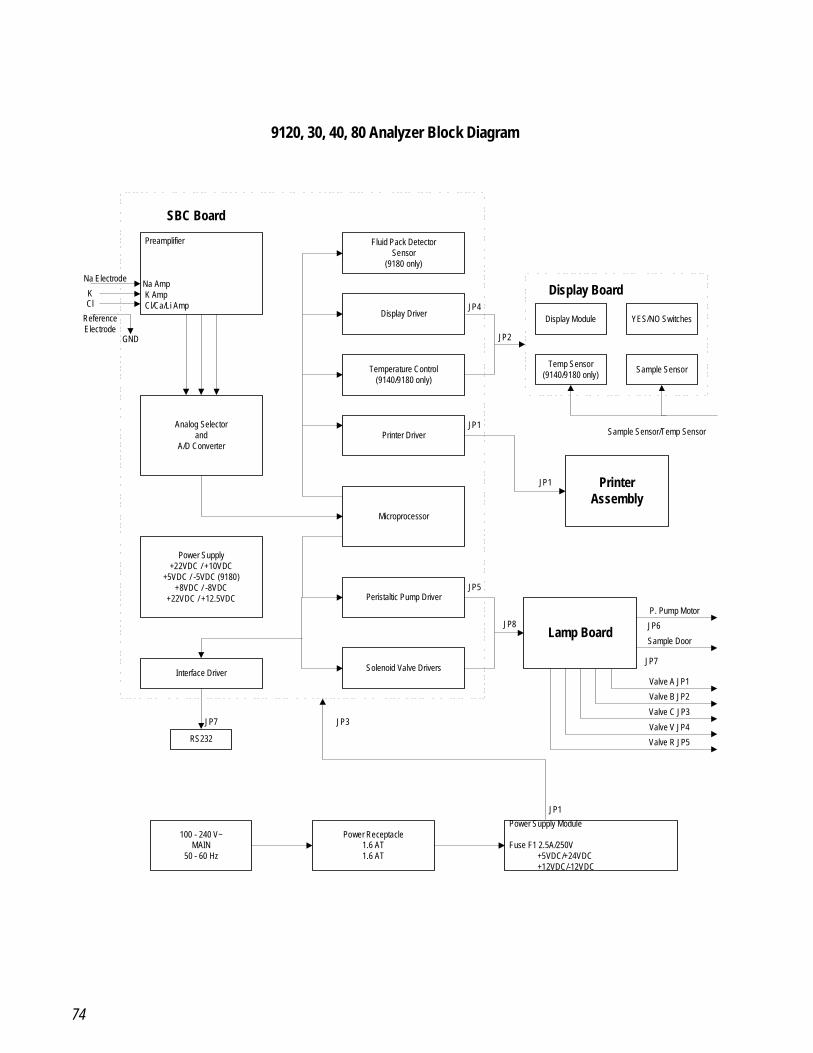
74
Preamplifier
Na Amp K Amp Cl/Ca/Li Amp
Analog Selectorand
A/D Converter
Power Supply+22VDC / +10VDC
+5VDC / -5VDC (9180)+8VDC / -8VDC
+22VDC / +12.5VDC
Interface Driver
RS232
100 - 240 V~MAIN
50 - 60 Hz
Fluid Pack DetectorSensor
(9180 only)
Display Driver
Temperature Control(9140/9180 only)
Printer Driver
Microprocessor
Peristaltic Pump Driver
Solenoid Valve Drivers
Power Receptacle1.6 AT1.6 AT
Display Module YES/NO Switches
Temp Sensor(9140/9180 only) Sample Sensor
PrinterAssembly
Lamp Board
Power Supply Module
Fuse F1 2.5A/250V +5VDC/+24VDC +12VDC/-12VDC
Na Electrode
KCl
ReferenceElectrode
GND
SBC Board
Display Board
Sample Sensor/Temp Sensor
P. Pump Motor
JP6
Sample Door
JP7
Valve A JP1
Valve B JP2
Valve C JP3
Valve V JP4
Valve R JP5
JP8
JP5
JP1
JP1
JP4
JP2
JP7 JP3
JP1
9120, 30, 40, 80 Analyzer Block Diagram
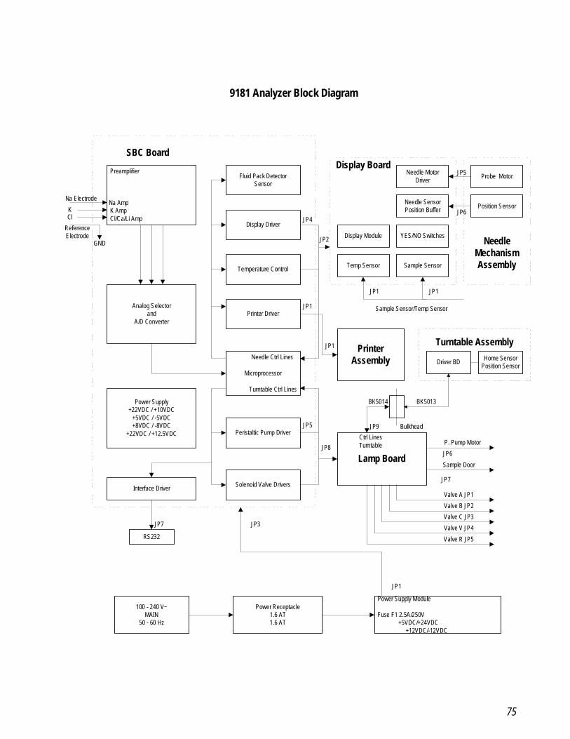
75
Preamplifier
Na Amp K Amp Cl/Ca/Li Amp
Analog Selectorand
A/D Converter
Power Supply+22VDC / +10VDC
+5VDC / -5VDC+8VDC / -8VDC
+22VDC / +12.5VDC
Interface Driver
RS232
100 - 240 V~MAIN
50 - 60 Hz
Fluid Pack DetectorSensor
Display Driver
Temperature Control
Printer Driver
Microprocessor
Peristaltic Pump Driver
Solenoid Valve Drivers
Power Receptacle1.6 AT1.6 AT
Display Module YES/NO Switches
Temp Sensor Sample Sensor
PrinterAssembly
Lamp Board
Power Supply Module
Fuse F1 2.5A/250V +5VDC/+24VDC
+12VDC/-12VDC
Na Electrode
KCl
ReferenceElectrode
GND
SBC BoardDisplay Board
Sample Sensor/Temp Sensor
P. Pump Motor
JP6
Sample Door
JP7
Valve A JP1
Valve B JP2
Valve C JP3
Valve V JP4
Valve R JP5
JP8
JP5
JP1
JP1
JP4
JP2
JP7 JP3
JP1
Needle SensorPosition Buffer
Needle MotorDriver
Probe Motor
Position Sensor
NeedleMechanismAssembly
JP1 JP1
JP6
JP5
Turntable Assembly
Driver BD Home SensorPosition Sensor
Bulkhead
BK5013BK5014
JP9
Ctrl LinesTurntable
Turntable Ctrl Lines
Needle Ctrl Lines
9181 Analyzer Block Diagram
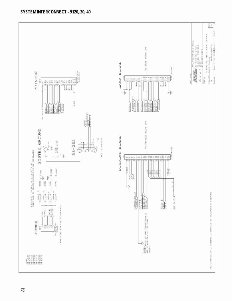
76
Date: April 10, 1996Sheet 1of 9
SizeDocument Number
REV
BINTERCONNECT
D
Title
SCHEMATIC, MAIN BOARD ISE/PH
(404)587-4040
30077
Roswell, Georgia
33 Mansell Court
AVL Scientific Corp.
A1B1A2B2A3B3A4B4A5B5A6B6A7B7A8B8A9B9A10
B10
JP1
EZC10DRXH
PRINTER
MOTOR-
TACHO
FEED
CHECK
DOT1-
DOT2-
DOT3-
DOT4-
DOT5-
DOT6-
DOT7-
PRINTVCC
SYSTEM GROUND
AMP
R900-R903 DO NOT PHYSICALLY EXIST
THEY ARE TO ALLOW GROUNDS TO BE SEPARATED
1JP2
62650-1
1
2R900
0
1
2R901
0
1
2R9020
1
2R9030
1 2
R904
270K_1/4W
PGND
SGND
AGND
DGND
PGND
SGND
GND
POWER
MATES WITH MOLEX 09-50-8073
MOLEX
|LINK
|MB1.SCH
|MB2.SCH
|MB3.SCH
|MB4.SCH
|MB5.SCH
|MB6.SCH
|MB7.SCH
|MB8.SCH
|MB9.SCH
1 2 3 4 5 6 7
JP3
26-60-4070
PVCC
PVCC
P+24V
P-12V
P+12V
RS-232
5 9 4 8 3 7 2 6 1
JP7
DB9P
AMP 1-747871-3
RS232OUT
RS232IN
RTS
CTS
PGND
SULLINS
TO LAMP BOARD JP8
1 2 3 4 5 6 7 8 9 1011121314151617181920212223242526
JP5
CHR26G-ND
LAMP BOARD
LAMP+
VALVEA-
VALVEB-
VALVEC-
VALVEV-
VALVER-
PHASEA
PHASEB
PHASEC
PHASED
DLED+
DCLOSED
VALVE+
OVERTEMP-
DISPLAY BOARD
TO DISPLAY BOARD JP2
1 2 3 4 5 6 7 8 9 1011121314151617181920212223242526
JP4
CHR26G-ND
SAMPLELED-
DATA/INST-
DISPEN
YES-
NO-
TEMP
DISPR/W-
SSEN
CONTRAST
SAMPLE
DD0
DD1
DD2
DD3
DD4
DD5
DD6
DD7
PGND
VCC
+5VA
VCC
NOTE:
AND CONNECTED AT THE SHIELD
AREA.
SAMPLEGND IS RUN INDIVIDUALLY
NOTE:REVISION D SCHEMATIC APPLIES TO REVISION H ARTWORK
DD[0..7]
DD[0..7]
+24V
+10V
mb1.sch
SYSTEM INTERCONNECT - 9120, 30, 40
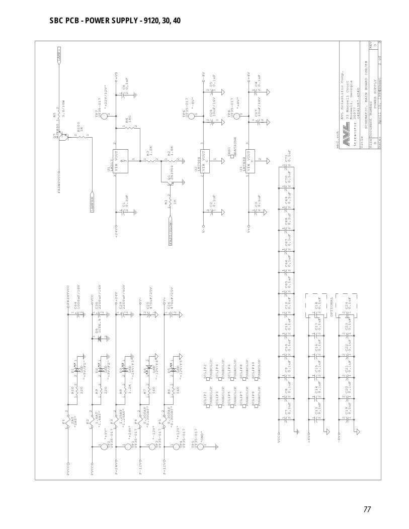
77
Date: April 10, 1996Sheet 2of 9
SizeDocument Number
REV
BPOWER SUPPLY
D
Title
SCHEMATIC, MAIN BOARD ISE/PH
(404)587-4040
30077
Roswell, Georgia
33 Mansell Court
AVL Scientific Corp.
"+22V/12V"
1
TP7
UT35-017
1
2R5
3.9/10W
Q7MJE800
12R103
1K
LAMP+
+VS
VIN
3
VOUT
2
A D J
1
U1LM317
LAMPEN
+24V
PRINTVCC
1 2
C29
2200uF/50V
1 2
C30
2200uF/16V
1 2
C64
1000uF/16V
21D6ICTE.5
VCC
PRINTVCC
+24V
"+5V"
"+5V/F1"
"+5V/F2"
"2AT"
"1.6AT"
1
2R9
220
1
2R10
220
1
TP2
UT35-017
1
2
F1
2AT
1
2
F2
1.6AT
1
2
F3
1.25AT
2
1D1
LED
2
1D2
LED
PVCC
PVCC
P+24V
"+24V"
"-12V"
"+12V"
"GND"
"+24V/F3"
"-12V/F4"
"+12V/F5"
"1.25AT"
"0.300AT"
"0.300AT"
1
2R6
560
1
2R7
560
1
2R8
1.2K
1
TP1
UT35-017
1
TP3
UT35-017
1
TP4
UT35-017
1
TP5
UT35-017
ZCLIP1
FUSECLIP
ZCLIP2
FUSECLIP
1
2
F4
0.300AT
1
2
F5
0.300AT
2
1D3
LED
2 1D4
LED
2
1D5
LED
P-12V
P+12V
12C25
470uF/25V
1 2
C26
470uF/25V
V+
V-
Q12N3904
1
2R1
1K
1 2
R21.8K
1 2
R31.2K
VIN
2
VOUT
3
C
1
U2LM7908
1 2C10.1uF
FAST/SLOW-
V-
"-8V"
1 2
R4180
1 2C60.1uF
1
TP6
UT35-017
-8V
"+8V"
1 2C40.1uF
1
TP8
UT35-017
1 2
C27
10uF/16V
12C28
10uF/16V
12C50.1uF
+8V
VIN
1
VOUT
3
C
2
U3LM7808
1 2C30.1uF
ZHS1
HEATSINK
1 2C67
0.1uF
1 2C68
0.1uF
1 2C69
0.1uF
1 2C70
0.1uF
1 2C71
0.1uF
12C20.1uF
V+
1 2C10
0.1uF
1 2C11
0.1uF
1 2C12
0.1uF
1 2C65
0.1uF
1 2C66
0.1uF
1 2C70.1uF
1 2C80.1uF
1 2C90.1uF
ZCLIP3
FUSECLIP
ZCLIP4
FUSECLIP
ZCLIP5
FUSECLIP
ZCLIP6
FUSECLIP
ZCLIP7
FUSECLIP
ZCLIP8
FUSECLIP
ZCLIP9
FUSECLIP
ZCLIP10
FUSECLIP
VCC
1 2C13
0.1uF
1 2C14
0.1uF
1 2C15
0.1uF
12C19
0.1uF
12C20
0.1uF
12C21
0.1uF
+8V
-8V
OPTIONAL
1 2C16
0.1uF
1 2C17
0.1uF
1 2C18
0.1uF
12C22
0.1uF
12C23
0.1uF
12C24
0.1uF
mb2.sch
SBC PCB - POWER SUPPLY - 9120, 30, 40
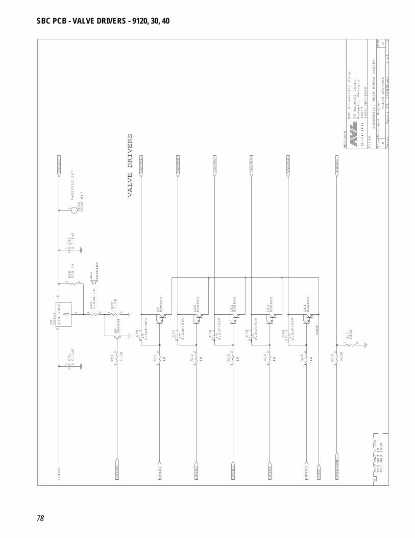
78
Date: April 10, 1996Sheet 3of 9
SizeDocument Number
REV
BVALVE DRIVERS
D
Title
SCHEMATIC, MAIN BOARD ISE/PH
(404)587-4040
30077
Roswell, Georgia
33 Mansell Court
AVL Scientific Corp.
"+22V/12.5V"
1 2C32
0.1uF
1
TP16
UT35-017
VALVE+
Q82N3904
VIN
3
VOUT
2
A D J
1
U5LM317
1 2C31
0.1uF
1
2R21
4.7K
ZHS2
HEATSINK
1 2
R18
200 1%
1 2
R19
1.82K 1%
1 2
R20
1.5K
VALVE-
+24V
OPEN1
OPEN2
1
2R11
1K
1
2R12
1K
Q9MJE800
Q10
MJE800
1 2C36
2.2uF/50V
1 2C37
2.2uF/50V
1 2C38
2.2uF/50V
VALVE DRIVERS
VALVEA-
VALVEB-
VALVEC-
VALVEV-
VALVER-
1
2R13
1K
1
2R14
1K
Q11
MJE800
Q12
MJE800
1 2C39
2.2uF/50V
1 2C40
2.2uF/50V
OPEN3
OPEN4
R20 WAS 1K
R17 WAS 100K
C R19 WAS 2.37K
OPEN5
OVERTEMP-
SGND
1
2R15
1K
1
2R16
360K
Q13
MJE800
1 2
R17
180K
SGND
THERM-
mb3.sch
SBC PCB - VALVE DRIVERS - 9120, 30, 40
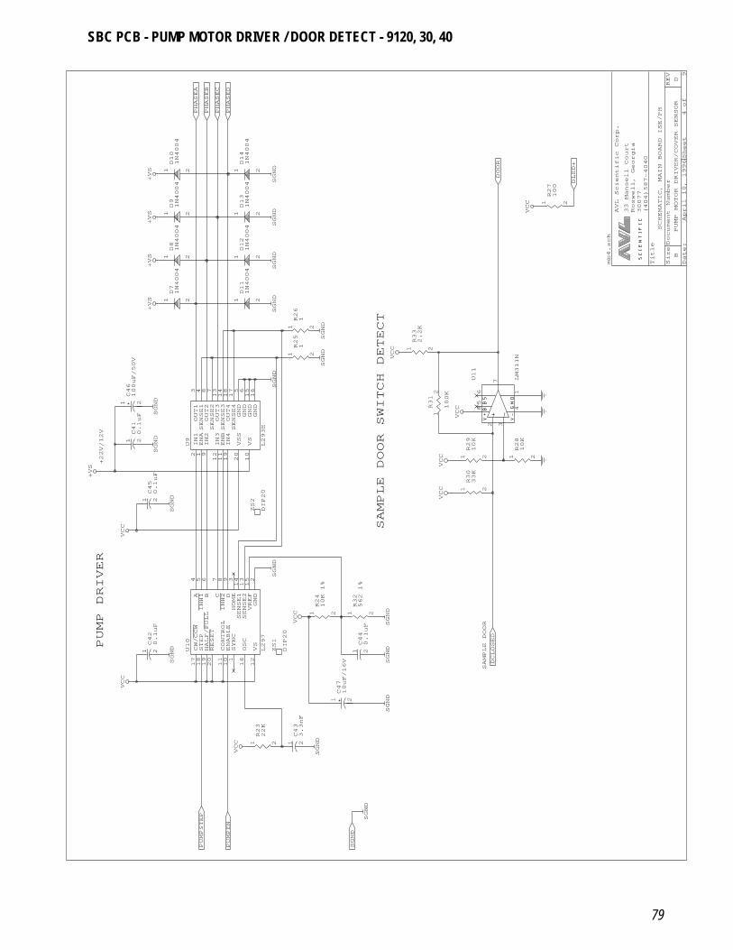
79
Date: April 10, 1996Sheet 4of 9
SizeDocument Number
REV
BPUMP MOTOR DRIVER/COVER SENSOR
D
Title
SCHEMATIC, MAIN BOARD ISE/PH
(404)587-4040
30077
Roswell, Georgia
33 Mansell Court
AVL Scientific Corp.
21D81N4004
21D91N4004
21D10
1N4004
PHASEA
PHASEB
PHASEC
+VS
+VS
+VS
+22V/12V
IN1
2
ENA
1
IN2
9
IN3
12
ENB
11
IN4
19
OUT1
3
OUT2
8
OUT3
13
OUT4
18
GND
5
GND
6
GND
15
VSS
20
VS
10
GND
16
SENSE1
4
SENSE2
7
SENSE3
14
SENSE4
17
U9
L293E
1 2
C46
100uF/50V
1 2C41
0.1uF
21D71N4004
+VS
SGND
SGND
PUMP DRIVER
A 4
INH1
5
B 6
C 7
INH2
8
D 9
SENSE1
14
SENSE2
13
VREF
15
CW/CCW
17
STEP
18
HALF/FULL
19
RESET
20
CONTROL
11
ENABLE
10
GND
2
VS
12
OSC
16
SYNC
1
HOME
3
U10
L297
1 2C42
0.1uF
1 2C45
0.1uF+VS
VCC
SGND
SGND
PUMPSTEP
VCC
1 2
R23
22K
1 2C43
3.3nF
1 2
C47
10uF/16V
PUMPEN
SGND
VCC
SGND
SGND
1 2C44
0.1uF
ZS1
DIP20
ZS2
DIP20
1 2
R24
10K 1%
1 2
R32
562 1%
VCC
SGND
1 2
R25
1
1 2
R26
1
21D11
1N4004
SGND
SGND
SGND
SGND
21D12
1N4004
21D13
1N4004
21D14
1N4004
PHASED
SGND
SGND
SGND
DOOR
2
3
7
85
6
41
U11
LM311N
1 2
R28
10K
1 2
R29
10K
1 2
R33
2.2K
1
2R31
100K
VCC
VCC
VCC
SAMPLE DOOR SWITCH DETECT
1 2
R30
33K
VCC
SGND
SGND
SAMPLE DOOR
DCLOSED
SGND
mb4.sch
1 2
R27
100
DLED+
VCC
SBC PCB - PUMP MOTOR DRIVER / DOOR DETECT - 9120, 30, 40
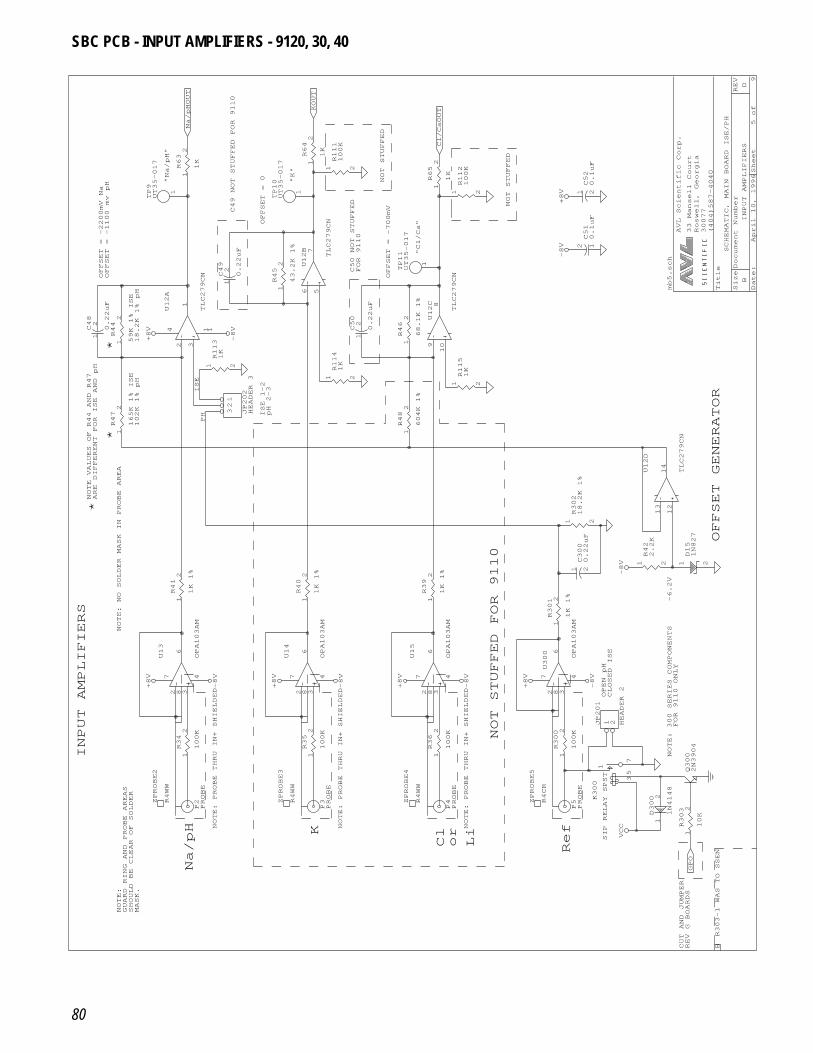
80
Date: April 10, 1996Sheet 5of 9
SizeDocument Number
REV
BINPUT AMPLIFIERS
D
Title
SCHEMATIC, MAIN BOARD ISE/PH
(404)587-4040
30077
Roswell, Georgia
33 Mansell Court
AVL Scientific Corp.
"Na/pH"
C49 NOT STUFFED FOR 9110
OFFSET = -1100 mv pH
OFFSET = -2200mV Na
1
2C49
0.22uF
1
TP9
UT35-017
1
2R63
1K
Na/pHOUT
ARE DIFFERENT FOR ISE AND pH
NOTE VALUES OF R44 AND R47
*
**
ISE
PH
1
2C48
0.22uF
2
3
1
1 14U12A
TLC279CN
1
2R47
165K 1% ISE
102K 1% pH
1
2R44
59K 1% ISE
18.2K 1% pH
12
3 JP202
HEADER 3
1 2
R113
1K
+8V
-8V
NOTE: NO SOLDER MASK IN PROBE AREA
3
8
2
7
6
4
U13
OPA103AM
1
2R41
1K 1%
+8V
-8V
NOTE: PROBE THRU IN+ SHIELDED
INPUT AMPLIFIERS
NOTE:
GUARD RING AND PROBE AREAS
SHOULD BE CLEAR OF SOLDER
MASK.
Na/pH
P2PROBE
1
2R34
100K
ZPROBE2
R4WW
NOTE: PROBE THRU IN+ SHIELDED
KP3PROBE
1
2R35
100K
ZPROBE4
R4WW
ZPROBE3
R4WW
3
8
2
7
6
4
U14
OPA103AM
1
2R40
1K 1%
+8V
+8V
-8V
ISE 1-2
pH 2-3
1
2C50
0.22uF
1
2R46
68.1K 1%
1
2R48
604K 1%
1 2
R114
1K
OFFSET = 0 "K"
C50 NOT STUFFED
FOR 9110
NOT STUFFED
OFFSET = -700mV
1
TP10
UT35-017
1
TP11
UT35-017
1
2R45
43.2K 1%
1
2R64
1K
6
5
7
U12B
TLC279CN
1 2
R111
100K
KOUT
NOT STUFFED
1 2C52
0.1uF
1
2R65
1K
12C51
0.1uF
1 2
R112
100K
-8V
+8V
"Cl/Ca"
Cl/CaOUT
9
10
8
U12C
TLC279CN
1 2
R115
1K
3
8
2
7
6
4
U15
OPA103AM
1
2R39
1K 1% 1 2
C300
0.22uF
1
2R301
1K 1%
1 2
R302
18.2K 1%
3
8
2
7
6
4
U300 OPA103AM
+8V
-8V
-8V
NOTE: PROBE THRU IN+ SHIELDED
Ref
Clor
Li
NOT STUFFED FOR 9110
P4PROBE
1
2R36
100K
P5PROBE
ZPROBE5
R4CR
1
2R300
100K
NOTE: 300 SERIES COMPONENTS
BR303-1 WAS TO SSEN
CUT AND JUMPER
REV G BOARDS
1
2R303
10K
Q300
2N3904
7
1
53
K300
SIP RELAY SPST
2 1D300
1N4148
GPO
VCC
-6.2V
OFFSET GENERATOR
FOR 9110 ONLY
OPEN pH
CLOSED ISE
1 2
R42
2.2K
1 2
D15
1N827
1 2JP201
HEADER 2
-8V
13
12
14
U12D
TLC279CN
mb5.sch
SBC PCB - INPUT AMPLIFIERS - 9120, 30, 40
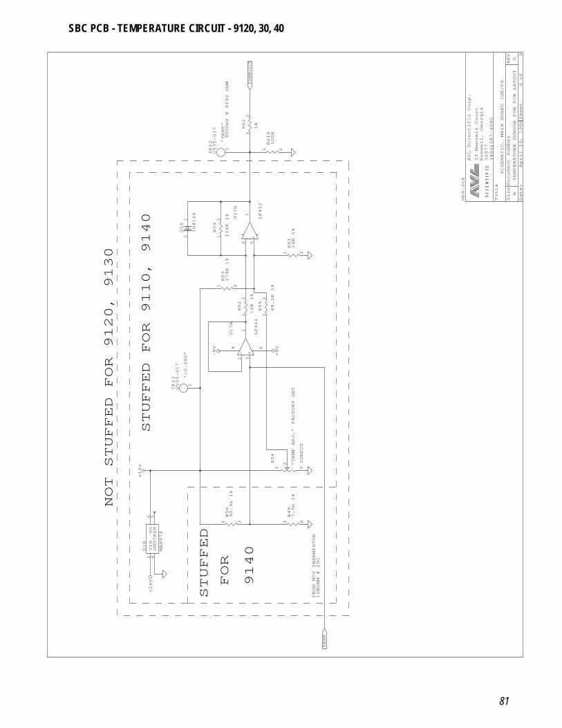
81
Date: April 10, 1996Sheet 6of 9
SizeDocument Number
REV
BTEMPERATURE SENSOR FOR PCB LAYOUT
D
Title
SCHEMATIC, MAIN BOARD ISE/PH
(404)587-4040
30077
Roswell, Georgia
33 Mansell Court
AVL Scientific Corp.
STUFFED FOR 9110, 9140
+10v
NOT STUFFED FOR 9120, 9130
VIN
2
GND
4
TRIM
5
VO
6
U18
MAX674
+24V
STUFFED
FOR
9140
1 2
R56
90.9k 1%
"10.00V"
1
TP13
UT35-017
1 3
2R54
10KPOT
3
2
1
84U17A
LF412
5
6
7
U17B
LF412
1
2R55
68.1K 1%
1
2R52
10K 1%
1
2R59
118K 1%
1 2
R53
274K 1%
2
1D16
1N4148
-8V
+8V
"TEMP"
3000mV @ 8192 OHM
1
TP12
UT35-017
1 2
R110
100K
1
2R62
1K
TEMPOUT
1 2
R51
10K 1%
"TEMP ADJ."
FACTORY SET
FROM NTC THERMISTOR
10KOHM @ 25C
1 2
R49
7.5k 1%
TEMP
mb6.sch
SBC PCB - TEMPERATURE CIRCUIT - 9120, 30, 40
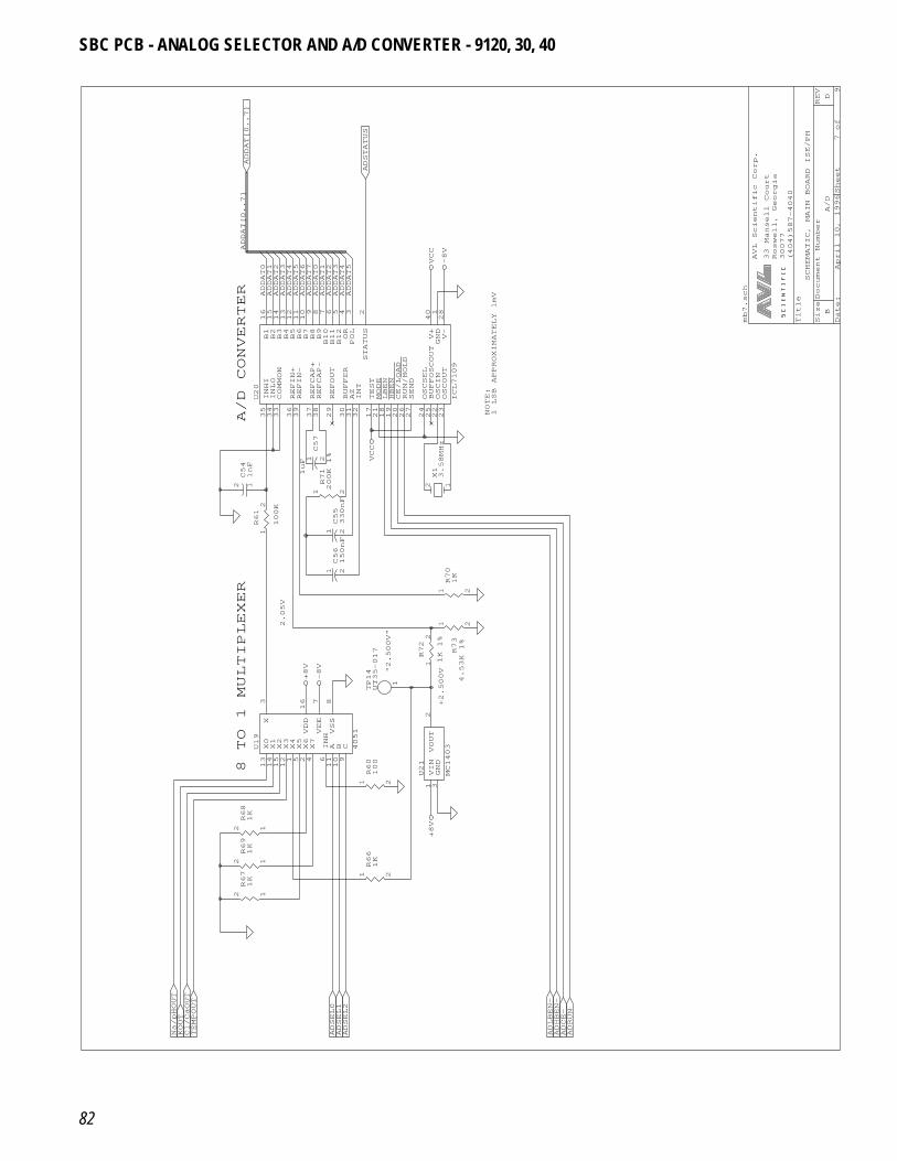
82
Date: April 10, 1996Sheet 7of 9
SizeDocument Number
REV
BA/D
D
Title
SCHEMATIC, MAIN BOARD ISE/PH
(404)587-4040
30077
Roswell, Georgia
33 Mansell Court
AVL Scientific Corp.
ADDAT[0..7]
ADDAT0
ADDAT[0..7]
A/D CONVERTER
B1
16
B2
15
B3
14
B4
13
B5
12
B6
11
B7
10
B8
9
B9
8
B10
7
B11
6
B12
5
OR
4
POL
3
STATUS
2
INHI
35
INLO
34
COMMON
33
REFIN+
36
REFIN-
39
REFCAP+
37
REFCAP-
38
REFOUT
29
BUFFER
30
AZ
31
INT
32
TEST
17
MODE
21
LBEN
18
HBEN
19
CE/LOAD
20
RUN/HOLD
26
SEND
27
OSCSEL
24
BUFFOSCOUT
25
OSCIN
22
OSCOUT
23
V-
28
GND
1
V+
40
U20
ICL7109
1
2R61
100K
12C54
1nF
8 TO 1 MULTIPLEXER
X0
13
X1
14
X2
15
X3
12
X4
1
X5
5
X6
2
X7
4
INH
6
A 11
B 10
C 9
X 3
VSS
8
VEE
7
VDD
16
U19
4051
12R69
1K
12R68
1K
12R67
1K
KOUT
TEMPOUT
Na/pHOUT
Cl/CaOUT
1 2
R66
1K
ADSEL0
ADSEL1
ADSEL2
+8V
+2.500V"2.500V"
2.05V
1 2
R60
100
VIN
1
GND
3
VOUT
2
U21
MC1403
1 2
R70
1K
1 2C56
150nF
1
TP14
UT35-017
1 2
R73
4.53K 1%
1
2R72
1K 1%
+8V
-8V
1 2C55
330nF
1 2C57
1uF
12X13.58MHz
1 2
R71
200K 1% VCC
ADSTATUS
ADDAT1
ADDAT2
ADDAT3
ADDAT4
ADDAT5
ADDAT6
ADDAT7
ADDAT0
ADDAT1
ADDAT2
ADDAT3
ADDAT4
ADDAT5
VCC
-8V
NOTE:
1 LSB APPROXIMATELY 1mV
ADLBEN-
ADHBEN-
ADCE-
ADRUN
mb7.sch
SBC PCB - ANALOG SELECTOR AND A/D CONVERTER - 9120, 30, 40
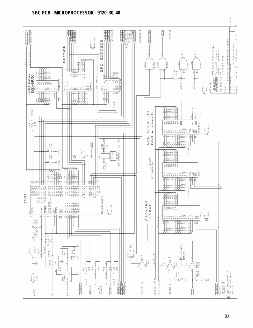
83
Date:
April 10, 1996Sheet
8
of
9
SizeDocument Number
REV
BMICROPROCESSOR
D
Title
SCHEMATIC, MAIN BOARD ISE/PH
(404)587-4040
30077
Roswell, Georgia
33 Mansell Court
AVL Scientific Corp.
DE-MUX
DECODE
D0
3
D1
4
D2
7
D3
8
D4
13
D5
14
D6
17
D7
18
OC
1
G 11
Q0
2
Q1
5
Q2
6
Q3
9
Q4
12
Q5
15
Q6
16
Q7
19
U23
74HCT373
I1/CLK
1
I2
2
I3
3
I4
4
I5
5
I6
6
I7
7
I8
8
I9
9
I10
10
I11
11
I12
13
O1
23
O2
22
O3
21
O4
20
O5
19
O6
18
O7
17
O8
16
O9
15
O10
14
U24
22V10
PROMEN-
RD-
WR-
RAMEN0-
RAMEN1-
AD[0..7]
A[0..15]
A0A1A2A3A4A5A6A7
A[0..15]
AD[0..7]
ADDRESS
1 2R81
10K
12R80
10K
AD7
AD6
AD5
AD4
AD3
AD2
AD1
AD0
A8A7
VCC
VCC
VCC
CPU
1 2
R74
10M
IC3/PA0
34
IC2/PA1
33
IC1/PA2
32
OC5/OC1/PA3
31
OC4/OC1/PA4
30
OC3/OC1/PA5
29
OC2/OC1/PA6
28
PAI/OC1/PA7
27
AD0/PC0
9
AD1/PC1
10
AD2/PC2
11
AD3/PC3
12
AD4/PC4
13
AD5/PC5
14
AD6/PC6
15
AD7/PC7
16
A8/PB0
42
A9/PB1
41
A10/PB2
40
A11/PB3
39
A12/PB4
38
A13/PB5
37
A14/PB6
36
A15/PB7
35
AS/STRA
4
R/W/STRB
6
E 5
RXD/PD0
20
TXD/PD1
21
MISO/PD2
22
MOSI/PD3
23
SCK/PD4
24
SS/PD5
25
EXTAL
7
XTAL
8
RESET
17
MODA/LIR
3
MODB/VSTBY
2
IRQ
19
XIRQ
18
VRH
52
VRL
51
AN0/PE0
43
AN1/PE1
45
AN2/PE2
47
AN3/PE3
49
AN4/PE4
44
AN5/PE5
46
AN6/PE6
48
AN7/PE7
50
U31
MC68HC11A0FN
12R78
10K
AD0
AD1
AD2
AD3
AD4
AD5
AD6
AD7
A8A9A10
A11
A12
A13
12X28MHz
1
2R75
10K
VI
3
VO
1
C
2
U27
78M05
1 2C58
0.1uF
1
2R76
10K
1
2R101
10K
1 2C59
22pF
1 2C60
22pF
+5VA
VCC
VCC
+8V
VCC
1 2
JP6
1
2R82
10K
1
2R83
10K
1
2R84
10K
1
2R85
10K
MISO
SAMPLE
YES-
NO-
DOOR
FEED
CHECK
ADSTATUS
DISPBF
THERM-
VCC
VCC
VCC
VCC
1
2D17
1N4148
2-3
AVL ISE
pH JUMPER 3 TO VCC
ZS3
PLCC52
A14
A15
1-2
3-4
HANDSHAKE
OEM
1 2
R77
1K
1234
JP400
GPO
A15
A14
A13
A12
A11
A10
A9 A2A1A0
VCC
VCC
SPI STROBES
A 1
B 2
C 3
G1
6
G2A
4
G2B
5
Y0
15
Y1
14
Y2
13
Y3
12
Y4
11
Y5
10
Y6
9
Y7
7
U28
74HCT138
ZS6
DIP24/3 DISTR
VASTR
ADOSTR
PRSTR
PUMPEN
PUMPSTEP
ADISTR
BUZZER
VALVE-
FAST/SLOW-
A6A5A4A3
IOSTROBE-
2
3
U29A
1488
4
5
6
U29B
1488
9
10
8
U29C
1488
1 2
R116
10K
RS232OUT
MOSI
SCK
RESET-
LAMPEN
RTS
RTSO
VCC
NON-VOLATILE
RAM & CLOCK
A0
10
A1
9
A2
8
A3
7
A4
6
A5
5
A6
4
A7
3
A8
25
A9
24
A10
21
A11
23
A12
2
CS1
20
CS2
26
WE
27
OE
22
D0
11
D1
12
D2
13
D3
15
D4
16
D5
17
D6
18
D7
19
GND
14
VCC
28
INT
1
U22
MK48T08
AD0
AD1
AD2
AD3
AD4
AD5
AD6
AD7
AD0
AD1
AD2
AD3
AD4
AD5
AD6
AD7
A0A1A2A3A4A5A6A7A8A9A10
PROGRAM
EPROM
RAM
NOT STUFFED
A0
10
A1
9
A2
8
A3
7
A4
6
A5
5
A6
4
A7
3
A8
25
A9
24
A10
21
A11
23
A12
2
A13
26
A14
27
A15
1
CE
20
OE
22
O0
11
O1
12
O2
13
O3
15
O4
16
O5
17
O6
18
O7
19
U25
27512
A0
10
A1
9
A2
8
A3
7
A4
6
A5
5
A6
4
A7
3
A8
25
A9
24
A10
21
A11
23
A12
2
CS1
20
CS2
26
WE
27
OE
22
D0
11
D1
12
D2
13
D3
15
D4
16
D5
17
D6
18
D7
19
U26
6264
AD0
AD1
AD2
AD3
AD4
AD5
AD6
AD7
A0A1A2A3A4A5A6A7A8A9A10
A[0..15]
1
3
2
U30A
1489
10
8
9
U30C
1489
1 2
R86
10K
RS232IN
TACHO
AD[0..7]
A[0..15]
A0A1A2A3A4A5A6A7A8A9A10
AD[0..7]
V+
V+
1
2D18
1N4148
BR117 ADDED
pH TIE JP400-3
TO VCC
4
6
5
U30B
1489
PROMEN-
RD-
WR-
RAMEN0-
RAMEN1-
CTS
A12
A11
A13
A14
A15
V+12
R117
4.7K
ZS4
DIP28
A12
A11
VCC
ZS5
DIP28
A12
A11
VCC
VCC
mb8.sch
ZPWB1
PWB
12
13
11
U29D
1488
VCC
SBC PCB - MICROPROCESSOR - 9120, 30, 40
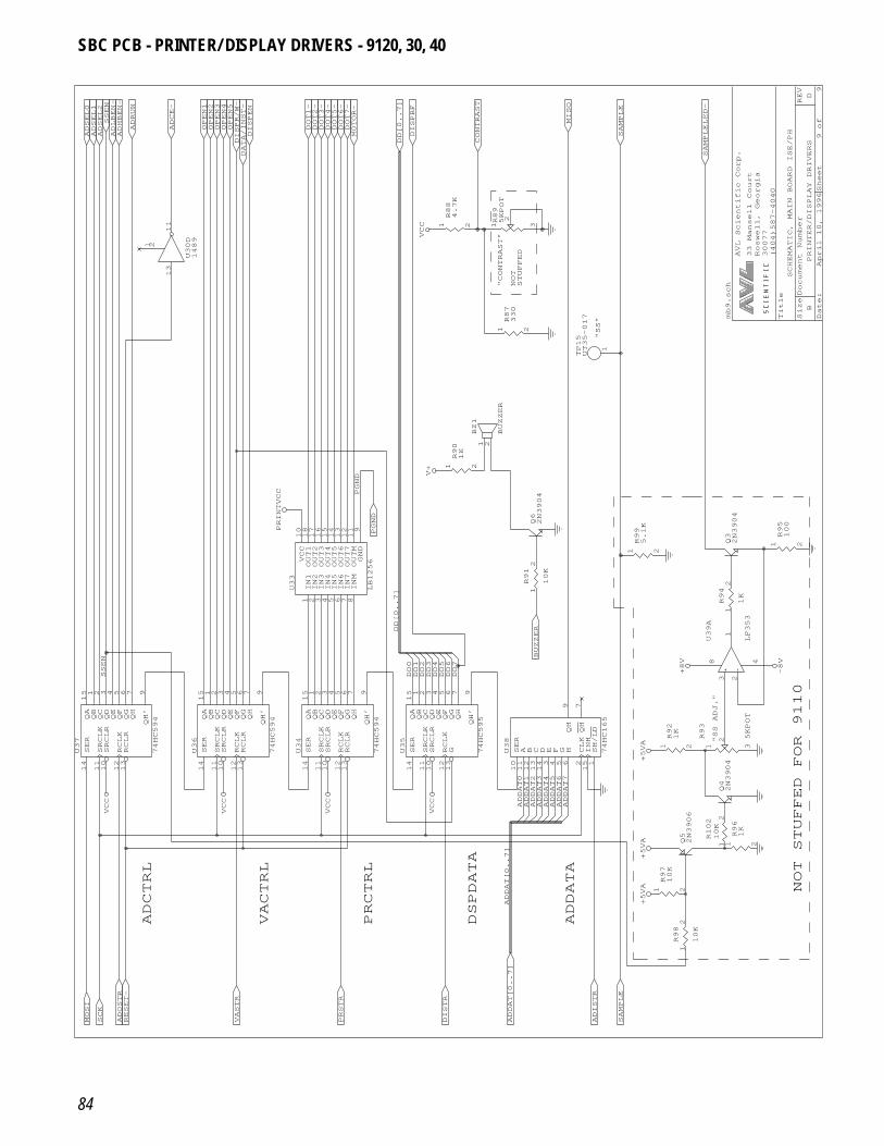
84
Date: April 10, 1996Sheet 9of 9
SizeDocument Number
REV
BPRINTER/DISPLAY DRIVERS
D
Title
SCHEMATIC, MAIN BOARD ISE/PH
(404)587-4040
30077
Roswell, Georgia
33 Mansell Court
AVL Scientific Corp.
13
11
1 2
U30D
1489
OPEN1
OPEN2
OPEN3
OPEN4
OPEN5
DATA/INST-
DISPEN
ADSEL0
ADSEL1
ADSEL2
ADRUN
ADCE-
ADHBEN-
ADLBEN-
DISPR/W-
SSEN
SER
14
SRCLK
11
SRCLR
10
RCLK
12
RCLR
13
QA
15
QB
1
QC
2
QD
3
QE
4
QF
5
QG
6
QH
7
QH’
9
U36
74HC594
SER
14
SRCLK
11
SRCLR
10
RCLK
12
RCLR
13
QA
15
QB
1
QC
2
QD
3
QE
4
QF
5
QG
6
QH
7
QH’
9
U37
74HC594
SSEN
VCC
VCC
ADCTRL
MOSI
SCK
RESET-
VASTR
ADOSTR
VACTRL
PRCTRL
PRSTR
DISTR
VCC
10
OUT1
18
OUT2
17
OUT3
16
OUT4
15
OUT5
14
OUT6
13
OUT7
12
OUTM
11
GND
9
IN1
1
IN2
2
IN3
3
IN4
4
IN5
5
IN6
6
IN7
7
INM
8
U33
LB1256
SER
14
SRCLK
11
SRCLR
10
RCLK
12
RCLR
13
QA
15
QB
1
QC
2
QD
3
QE
4
QF
5
QG
6
QH
7
QH’
9
U34
74HC594
SER
14
SRCLK
11
SRCLR
10
RCLK
12
G 13
QA
15
QB
1
QC
2
QD
3
QE
4
QF
5
QG
6
QH
7
QH’
9
U35
74HC595
DD0
DD1
DD2
DD3
DD4
DD5
DD[0..7]
VCC
VCC
PGND
PGND
PRINTVCC
V+
1 2
R88
4.7K
DOT1-
DOT2-
DOT3-
DOT4-
DOT5-
DOT6-
DOT7-
MOTOR-
DD[0..7]
DISPBF
VCC
"CONTRAST"
NOT
STUFFED
1 3
2R89
5KPOT
MISO
CONTRAST
SAMPLE
"SS"
1
2
BZ1
BUZZER
1 2
R90
1K
Q62N3904
1
TP15
UT35-017
1 2
R99
5.1K
1 2
R87
330
SER
10
A 11
B 12
C 13
D 14
E 3
F 4
G 5
H 6
CLK
2
INH
15
SH/LD
1
QH
9
QH
7
U38
74HC165
1
2R91
10K
BUZZER
DD6
DD7
DSPDATA
ADDATA
ADISTR
ADDAT[0..7]
SAMPLE
ADDAT[0..7]
ADDAT0
ADDAT1
ADDAT2
ADDAT3
ADDAT4
ADDAT5
ADDAT6
ADDAT7
NOT STUFFED FOR 9110
Q42N3904
Q52N3906
1 2
R97
10K
1
2R98
10K
1
2
R102
10K
1 2
R96
1K
+5VA
+5VA
"SS ADJ." 3
2
1
8 4
U39A
LF353
1 2
R92
1K
1 3
2R93
5KPOT
1
2R94
1K
+5VA
+8V
-8V
Q32N3904
1 2
R95
100
mb9.sch
SAMPLELED-
SBC PCB - PRINTER/ DISPLAY DRIVERS - 9120, 30, 40
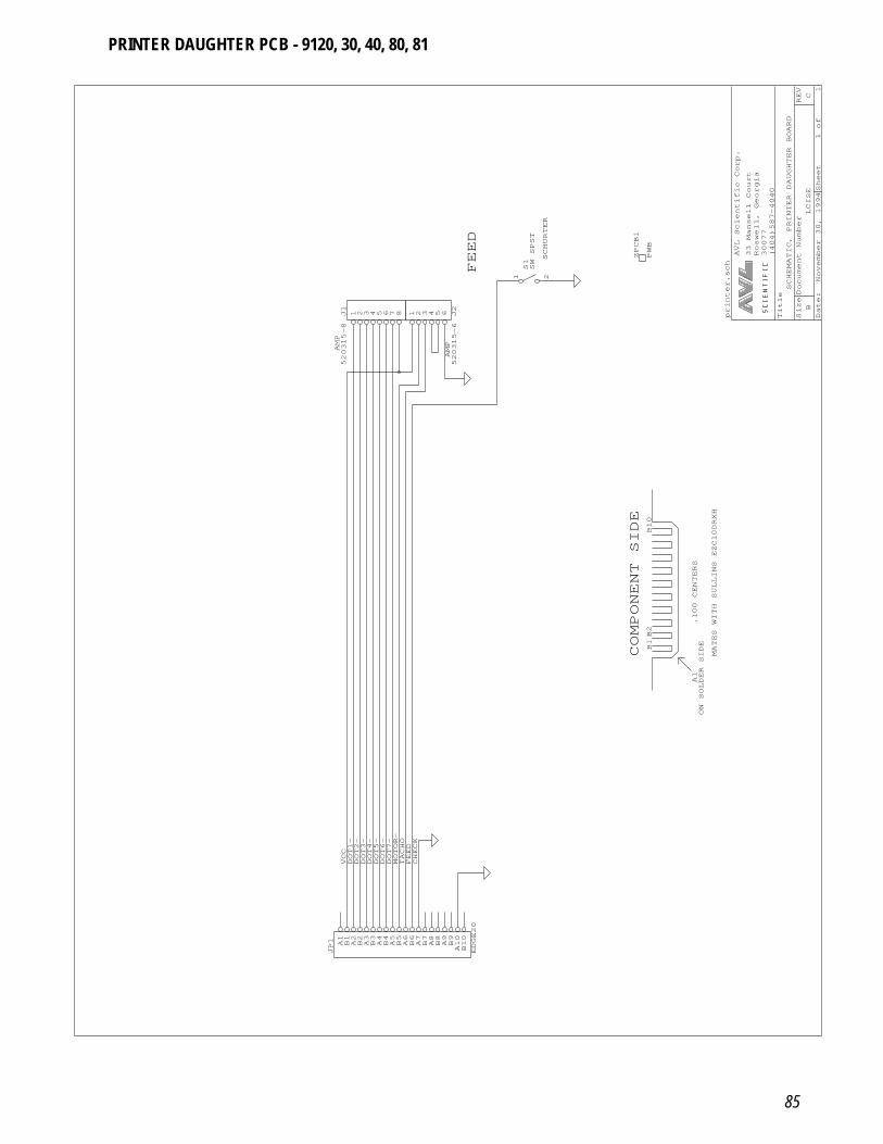
85
Date: November 30, 1994Sheet 1of 1
SizeDocument Number
REV
BLCISE
C
Title
SCHEMATIC, PRINTER DAUGHTER BOARD
(404)587-4040
30077
Roswell, Georgia
33 Mansell Court
AVL Scientific Corp.
A1B1A2B2A3B3A4B4A5B5A6B6A7B7A8B8A9B9
A10
B10
JP1
EDGE20
CHECK
VCC
MOTOR-
TACHO
DOT1-
DOT2-
DOT3-
DOT4-
DOT5-
DOT6-
DOT7-
FEED
AMP
1 2 3 4 5 6 7 8J1
520315-8
1 2 3 4 5 6 J2
520315-6
FEED
SCHURTER
1 2
S1SW SPST
AMP
COMPONENT SIDE
.100 CENTERS
B1B2
A1
ON SOLDER SIDE
MATES WITH SULLINS EZC10DRXH
B10
printer.sch
ZPCB1
PWB
PRINTER DAUGHTER PCB - 9120, 30, 40, 80, 81
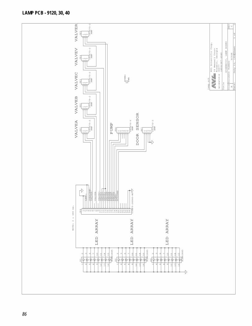
86
Date: July 11, 1996Sheet 1of 1
SizeDocument Number
REV
BLCISE
C
Title
SCHEMATIC, LAMP BOARD
(404)587-4040
30077
Roswell, Georgia
33 Mansell Court
AVL Scientific Corp.
NOTE: I = 480 ma.
LED ARRAY
2
3
6
7
10
11
14
15
1
4
5
8
9
12
13
16
U1
HLMP2885
2
3
6
7
10
11
14
15
1
4
5
8
9
12
13
16
U2
HLMP2885
VALVEA-
VALVEB-
VALVEC-
VALVEV-
VALVER-
PHASEA
PHASEB
PHASEC
PHASED
DLED+
LAMP+
DCLOSED
VALVE+
VALVE+
OVERTEMP-
1 2 3 4 5 6 7 8 91011121314151617181920212223242526
JP8
C3APT-2606G-ND
VALVEA
VALVEB
PUMP
AMP
AMP
1 2 3 4 5 6JP6
103670-5
1 2 3JP1
103670-2
1 2 3JP2
103670-2
VALVEC
VALVEV
VALVER
AMP
AMP
AMP
ZPWB1
PWB
1 2 3JP3
103670-2
1 2 3JP4
103670-2
1 2 3JP5
103670-2
DOOR SENSOR
AMP
AMP
1 2 3 4JP7
103670-3
LED ARRAY
LED ARRAY
2
3
6
7
10
11
14
15
1
4
5
8
9
12
13
16
U3
HLMP2885
lamp.sch
LAMP PCB - 9120, 30, 40
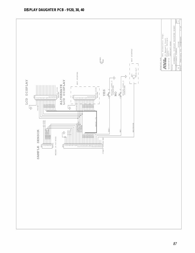
87
Date: February 19, 1992Sheet 1of 1
SizeDocument Number
REV
BLCISE
C
Title
SCHEMATIC, DISPLAY DAUGHTER BOARD
(404)587-4040
30077
Roswell, Georgia
33 Mansell Court
AVL Scientific Corp.
LCD DISPLAY
1 2 3 4 5 6 7 8 9 1011121314
JP4
22-03-2141
DD0
DD1
DD2
DD3
DD4
DD5
DD6
DD7
VCC
SAMPLE SENSOR
MOLEX 15-43-8566
1 2 3 4 5 6
JP1
RJ12
SAMPLELED-
SAMPLEPT
TEMP
SAMPLEGND
+5VA
+5VA
1 2 3 4 5 6 7 8 91011121314151617181920212223242526
JP2
C3APT-2606G-ND
DD0
DD1
DD2
DD3
DD4
DD5
DD6
DD7
DD[0..7]
DISPEN
DISPR/W-
DATA/INST-
CONTRAST
VCC
VCC
+5VA
LCD DISPLAY
MOLEX
MOLEX
ALTERNATE
NOT STUFFED
1 2 3 4 5 6 7 8 9 1011121314
JP3
22-03-2141
DD0
DD1
DD2
DD3
DD4
DD5
DD6
DD7
VCC
NOT STUFFED
ZPWB1
PWB
YES
NOSCHURTER
SCHURTER
1TP1
UT35-017
1
2
S2
IP1241.1082.3
1
2
S1
IP1241.1082.3
YES-
NO-
MAINDOOR
display.sch
DISPLAY DAUGHTER PCB - 9120, 30, 40
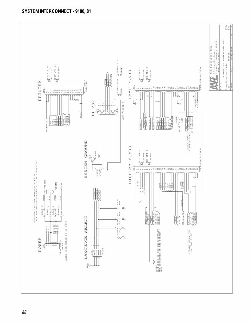
88
Date: May 7, 1996Sheet 2of 11
SizeDocument Number
REV
BZD5015
C
Title
SCHEMATIC, MAIN BOARD 9180
(404) 587-4040
Roswell, Georgia 30076
33 Mansell Court
AVL Scientific Corp.
ZFST-JP1-1
FASTENER2
ZFST-JP1-2
FASTENER2
PRINTER
A1B1A2B2A3B3A4B4A5B5A6B6A7B7A8B8A9B9A10
B10
JP1
EZC10DRXH
MOTOR-
TACHO
FEED
CHECK
DOT1-
DOT2-
DOT3-
DOT4-
DOT5-
DOT6-
DOT7-
PRINTVCC
R900-R903 DO NOT PHYSICALLY EXIST
THEY ARE TO ALLOW GROUNDS TO BE SEPARATED
1
2R900
0
1
2R901
0
1
2R9020
1
2R9030
AGND
PGND
SGND
DGND
PGND
SGND
DGND
POWER
MATES WITH MOLEX 09-50-8073
MOLEX
1 2 3 4 5 6 7
JP3
26-60-4070
PVCC
PVCC
P+24V
P-12V
P+12V
LANGUAGE SELECT
1 2
R905
10K
1 2
R906
10K
1
2
3
4
8 7 6 5
SW1
78B04
VCC
SYSTEM GROUND
1JP2
62650-1
1 2
R907
10K
1 2
R908
10K
1 2
R926
270K
LGSEL0
LGSEL1
LGSEL2
LGSEL3
RS-232
AMP
SULLINS
AMP 745061-4
5 9 4 8 3 7 2 6 1
JP7
DB9P
PGND
ZSCRW-JP7-1
SCREW
RS232OUT
RS232IN
RTS
CTS
ZSCRW-JP7-2
SCREW
1 2 3 4 5 6 7 8 9 10111213141516171819202122232425262728293031323334
JP5
CWN-300-34-0000
ZEJ-JP5-2
EJECTOR
ZEJ-JP5-1
EJECTOR
LAMP BOARD
1
2R904
10K
LAMP+
VALVEA-
VALVEB-
VALVEC-
VALVEV-
VALVER-
PHASEA
PHASEB
PHASEC
PHASED
DLED+
DCLOSED
VALVE+
OVERTEMP-
VCC
DISPLAY BOARD
SAMPLELED-
DATA/INST-
DISPEN
YES-
NO-
TEMP
DISPR/W-
SSEN
CONTRAST
SAMPLE
DD0
DD1
DD2
DD3
DD4
DD5
DD6
DD7
PGND
VCC
+5VA
VCC
1 2 3 4 5 6 7 8 9 10111213141516171819202122232425262728293031323334
JP4
CWN-300-34-0000
ZEJ-JP4-1
EJECTOR
ZEJ-JP4-2
EJECTOR
NOTE:
AND CONNECTED AT THE SHIELD
AREA.
SAMPLEGND IS RUN INDIVIDUALLY
NEEDLE MECHANISM
CONTROL LINES
NDMOTEN-
DD[0..7]
ROTCLK
CW/CCW
UPNDPOS
LWNDPOS
DD[0..7]
+24V
+10V
TURN TABLE
CONTROL LINES
TABLEPRES
UPTBPOS
LWTBPOS
TBMOTEN-
VCC
+24V
SYSTEM INTERCONNECT - 9180, 81
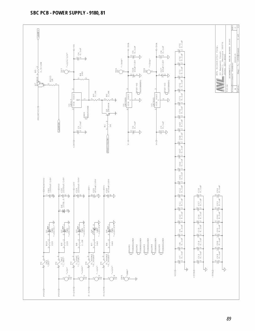
89
Date: May 7, 1996Sheet 3of 11
SizeDocument Number
REV
BZD5015
C
Title
SCHEMATIC, MAIN BOARD 9180
(404) 587-4040
Roswell, Georgia 30076
33 Mansell Court
AVL Scientific Corp.
"+22V/12V"
1
2R5
3.9/10W
Q7MJE800
12R103
1K
LAMP+
+VS
1
TP7
TP
VIN
3
VOUT
2
A D J
1
U1LM317
LAMPEN
+24V
PRINTVCC
1 2
C29
2200uF/50V
1 2
C30
2200uF/16V
1 2
C64
1000uF/16V
21D6ICTE.5
VCC
PRINTVCC
+24V
"+5V"
"+5V/F1"
"+5V/F2"
"2AT"
"1.6AT"
1
2R9
220
1
2R10
220
1
2
F1
2AT
1
2
F2
1.6AT
1
2
F3
1.25AT
2
1D1
LED
2
1D2
LED
PVCC
PVCC
P+24V
1
TP2
TP
"+24V"
"-12V"
"+12V"
"GND"
"+24V/F3"
"-12V/F4"
"+12V/F5"
"1.25AT"
"0.300AT"
"0.300AT"
1
2R6
560
1
2R7
560
1
2R8
1.2K
1
2
F4
0.300AT
1
2
F5
0.300AT
2
1D3
LED
2 1D4
LED
2
1D5
LED
P-12V
P+12V
1
TP1
TP 1
TP3
TP 1
TP4
TP 1
TP5
TP
ZHLDR1
FUSEHOLDER
12C25
470uF/25V
1 2
C26
470uF/25V
V+
V-
Q12N3904
1
2R1
1K
1 2
R21.8K
1 2
R31.2K
1 2C10.1uF
ZHS1
HEATSINK VIN
2
VOUT
3
C
1
U2LM7905
FAST/SLOW-
V-
"-5VA"
1 2
R4180
1 2C60.1uF -5VA
1
TP6
TP
"+5VA"
1 2C40.1uF
1 2
C27
10uF/16V
12C28
10uF/16V
12C50.1uF
1 2C72
0.1uF
1 2C73
0.1uF
1 2C74
0.1uF
1 2C75
0.1uF
+5VA
1
TP8
TP
1 2C30.1uF
1 2C67
0.1uF
1 2C68
0.1uF
1 2C69
0.1uF
1 2C70
0.1uF
1 2C71
0.1uF
12C20.1uF
VIN
1
VOUT
3
C
2
U3LM7805
V+
ZFST-U3
FASTENER1
ZFST-U2
FASTENER1
1 2C10
0.1uF
1 2C11
0.1uF
1 2C12
0.1uF
1 2C65
0.1uF
1 2C66
0.1uF
1 2C70.1uF
1 2C80.1uF
1 2C90.1uF
VCC
ZHLDR2
FUSEHOLDER
ZHLDR3
FUSEHOLDER
ZHLDR4
FUSEHOLDER
ZHLDR5
FUSEHOLDER
1 2C13
0.1uF
1 2C14
0.1uF
1 2C15
0.1uF
12C19
0.1uF
12C20
0.1uF
12C21
0.1uF
+5VA
-5VA
1 2C16
0.1uF
1 2C17
0.1uF
1 2C18
0.1uF
12C22
0.1uF
12C23
0.1uF
12C24
0.1uF
SBC PCB - POWER SUPPLY - 9180, 81
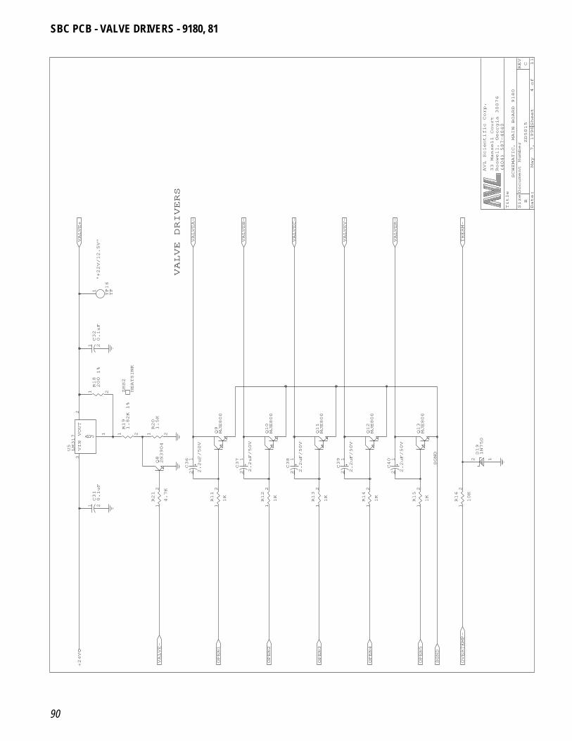
90
Date: May 7, 1996Sheet 4of 11
SizeDocument Number
REV
BZD5015
C
Title
SCHEMATIC, MAIN BOARD 9180
(404) 587-4040
Roswell, Georgia 30076
33 Mansell Court
AVL Scientific Corp.
"+22V/12.5V"
1 2C32
0.1uF
VALVE+
1
TP16
TP
Q82N3904
VIN
3
VOUT
2
A D J
1
U5LM317
1 2C31
0.1uF
1
2R21
4.7K
ZHS2
HEATSINK
1 2
R18
200 1%
1 2
R20
1.5K
1 2
R19
1.82K 1%
VALVE-
+24V
OPEN1
OPEN2
1
2R11
1K
1
2R12
1K
Q9MJE800
Q10
MJE800
1 2C36
2.2uF/50V
1 2C37
2.2uF/50V
1 2C38
2.2uF/50V
VALVE DRIVERS
VALVEA-
VALVEB-
VALVEC-
VALVEV-
VALVER-
1
2R13
1K
1
2R14
1K
Q11
MJE800
Q12
MJE800
1 2C39
2.2uF/50V
1 2C40
2.2uF/50V
OPEN3
OPEN4
OPEN5
OVERTEMP-
SGND
1
2R15
1K
Q13
MJE800
1
2R16
10K
12D19
1N750
SGND
THERM-
SBC PCB - VALVE DRIVERS - 9180, 81
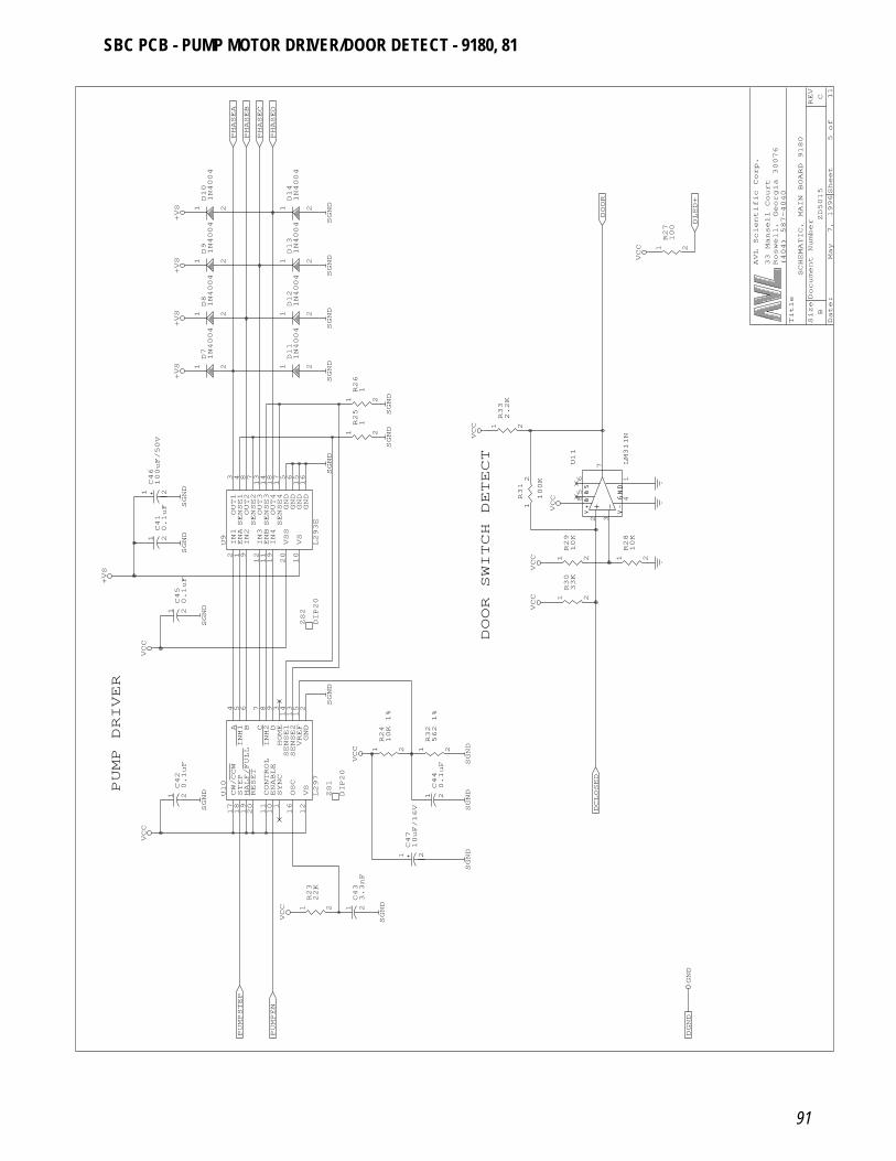
91
Date: May 7, 1996Sheet 5of 11
SizeDocument Number
REV
BZD5015
C
Title
SCHEMATIC, MAIN BOARD 9180
(404) 587-4040
Roswell, Georgia 30076
33 Mansell Court
AVL Scientific Corp.
21D81N4004
21D91N4004
21D10
1N4004
PHASEA
PHASEB
PHASEC
+VS
+VS
+VS
IN1
2
ENA
1
IN2
9
IN3
12
ENB
11
IN4
19
OUT1
3
OUT2
8
OUT3
13
OUT4
18
GND
5
GND
6
GND
15
VSS
20
VS
10
GND
16
SENSE1
4
SENSE2
7
SENSE3
14
SENSE4
17
U9
L293E
1 2
C46
100uF/50V
1 2C41
0.1uF
21D71N4004
+VS
SGND
SGND
PUMP DRIVER
A 4
INH1
5
B 6
C 7
INH2
8
D 9
SENSE1
14
SENSE2
13
VREF
15
CW/CCW
17
STEP
18
HALF/FULL
19
RESET
20
CONTROL
11
ENABLE
10
GND
2
VS
12
OSC
16
SYNC
1
HOME
3
U10
L297
1 2C42
0.1uF
1 2C45
0.1uF+VS
VCC
SGND
SGND
PUMPSTEP
VCC
1 2
R23
22K
1 2C43
3.3nF
1 2
C47
10uF/16V
PUMPEN
VCC
SGND
1 2C44
0.1uF
ZS1
DIP20
ZS2
DIP20
1 2
R24
10K 1%
1 2
R32
562 1%
VCC
SGND
1 2
R25
1
1 2
R26
1
21D11
1N4004
SGND
SGND
SGND
SGND
21D12
1N4004
21D13
1N4004
21D14
1N4004
PHASED
SGND
SGND
SGND
DOOR
2
3
7
85
6
41
U11
LM311N
1 2
R28
10K
1 2
R29
10K
1 2
R33
2.2K
1
2R31
100K
VCC
VCC
VCC
DOOR SWITCH DETECT
1 2
R30
33K
VCC
SGND
SGND
DCLOSED
SGND
DGND
GND
1 2
R27
100
DLED+
VCC
SBC PCB - PUMP MOTOR DRIVER/DOOR DETECT - 9180, 81
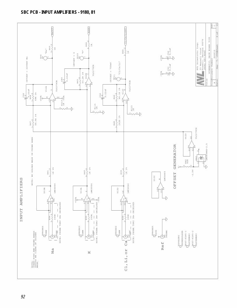
92
Date: May 7, 1996Sheet 6of 11
SizeDocument Number
REV
BZD5015
C
Title
SCHEMATIC, MAIN BOARD 9180
(404) 587-4040
Roswell, Georgia 30076
33 Mansell Court
AVL Scientific Corp.
OFFSET = 2200mV
Na
"Na"
1
2C49
0.22uF
1
2R63
1K
NaOUT
1
TP9
TP
1
2C48
0.22uF
2
3
1
1 14U12A
TLC279CN
1
2R44
59K 1%
1
2R47
66.5K 1%
1 2
R113
1K
+5VA
-5VA
NOTE: NO SOLDER MASK IN PROBE AREA
1
2R41
1K 1%
6
5
7
U13B
LMC6064
NOTE: PROBE THRU IN+ SHIELDED
INPUT AMPLIFIERS
NOTE:
GUARD RING AND PROBE AREAS
SHOULD BE CLEAR OF SOLDER
MASK.
Na
P2PROBE
1
2R34
100K
ZPROBE2
R4WW
NOTE: PROBE THRU IN+ SHIELDED
KP3PROBE
1
2R35
100K
ZPROBE4
R4WW
ZPROBE3
R4WW
1
2R40
1K 1%
2
3
1
1 14U13A
LMC6064
+5VA
-5VA
1
2C50
0.22uF
1
2R46
68.1K 1%
1 2
R114
1K
1
2R48
243K 1%
OFFSET = 0 "K"
OFFSET = 700mV
1
2R45
43.2K 1%
1
2R64
1K
6
5
7
U12B
TLC279CN
KOUT
1
TP11
TP
1
TP10
TP
"Cl/Ca/Li"
1 2C52
0.1uF
1
2R65
1K
12C51
0.1uF
Cl/Ca/LiOUT
+5VA
-5VA
9
10
8
U12C
TLC279CN
1 2
R115
1K
1
2R39
1K 1%
13
12
14
U13D
LMC6064
9
10
8
U13C
LMC6064
NOTE: PROBE THRU IN+ SHIELDED
Ref
Cl,Li,or Ca
P4PROBE
1
2R36
100K
P5PROBE
ZPROBE5
R4CR
ZFST-P2P5-1
FASTENER3
ZFST-P2P5-2
FASTENER3
ZSPHLDR1
PROBEHOLDER
-2.5V
OFFSET GENERATOR
1
2
3
U42
LM385BXZ-2.5
1 2
R42
82K
V-
13
12
14
U12D
TLC279CN
SBC PCB - INPUT AMPLIFIERS - 9180, 81
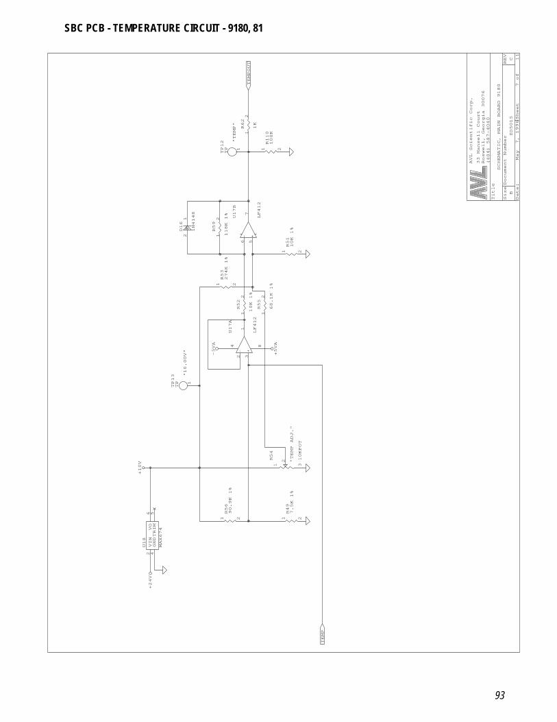
93
Date: May 7, 1996Sheet 7of 11
SizeDocument Number
REV
BZD5015
C
Title
SCHEMATIC, MAIN BOARD 9180
(404) 587-4040
Roswell, Georgia 30076
33 Mansell Court
AVL Scientific Corp.
+10V
VIN
2
GND
4
TRIM
5
VO
6
U18
MAX674
+24V
1 2
R56
90.9K 1%
"10.00V"
1 3
2R54
10KPOT
1
TP13
TP
3
2
1
84U17A
LF412
5
6
7
U17B
LF412
1
2R55
68.1K 1%
1
2R52
10K 1%
1
2R59
118K 1%
1 2
R53
274K 1%
2
1D16
1N4148
-5VA
+5VA
"TEMP"
1 2
R110
100K
1
2R62
1K
TEMPOUT
1
TP12
TP
1 2
R51
10K 1%
"TEMP ADJ."
1 2
R49
7.5K 1%
TEMP
SBC PCB - TEMPERATURE CIRCUIT - 9180, 81
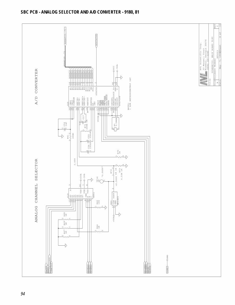
94
Date: May 7, 1996Sheet 8of 11
SizeDocument Number
REV
BZD5015
C
Title
SCHEMATIC, MAIN BOARD 9180
(404) 587-4040
Roswell, Georgia 30076
33 Mansell Court
AVL Scientific Corp.ADDAT[0..7]
ADDAT0
ADDAT[0..7]
A/D CONVERTER
B1
16
B2
15
B3
14
B4
13
B5
12
B6
11
B7
10
B8
9
B9
8
B10
7
B11
6
B12
5
OR
4
POL
3
STATUS
2
INHI
35
INLO
34
COMMON
33
REFIN+
36
REFIN-
39
REFCAP+
37
REFCAP-
38
REFOUT
29
BUFFER
30
AZ
31
INT
32
TEST
17
MODE
21
LBEN
18
HBEN
19
CE/LOAD
20
RUN/HOLD
26
SEND
27
OSCSEL
24
BUFFOSCOUT
25
OSCIN
22
OSCOUT
23
V-
28
GND
1
V+
40
U20
ICL7109
1
2R61
100K
12C54
1nF
X0
13
X1
14
X2
15
X3
12
X4
1
X5
5
X6
2
X7
4
INH
6
A 11
B 10
C 9
X 3
VSS
8
VEE
7
VDD
16
U19
4051
ANALOG CHANNEL SELECTOR
12R69
1K
12R68
1K
12R67
1K
KOUT
TEMPOUT
Cl/Ca/LiOUT
NaOUT
1 2
R66
1K
ADSEL0
ADSEL1
ADSEL2
+5VA
+2.500V"2.500V"
2.05V
1 2
R60
100
VIN
1
GND
3
VOUT
2
U21
MC1403
1 2
R70
1K
1 2C56
150nF
1 2
R73
4.53K 1%
1
2R72
1K 1%
+5VA
-5VA
1
TP14
TP
1 2C55
330nF
1 2C57
1uF
12X13.58MHz
1 2
R71
200K 1% VCC
ADSTATUS
ADDAT1
ADDAT2
ADDAT3
ADDAT4
ADDAT5
ADDAT6
ADDAT7
ADDAT0
ADDAT1
ADDAT2
ADDAT3
ADDAT4
ADDAT5
VCC
-5VA
NOTE:
1 LSB APPROXIMATELY 1mV
ADLBEN-
ADHBEN-
ADCE-
ADRUN
DGND
GND
SBC PCB - ANALOG SELECTOR AND A/D CONVERTER - 9180, 81
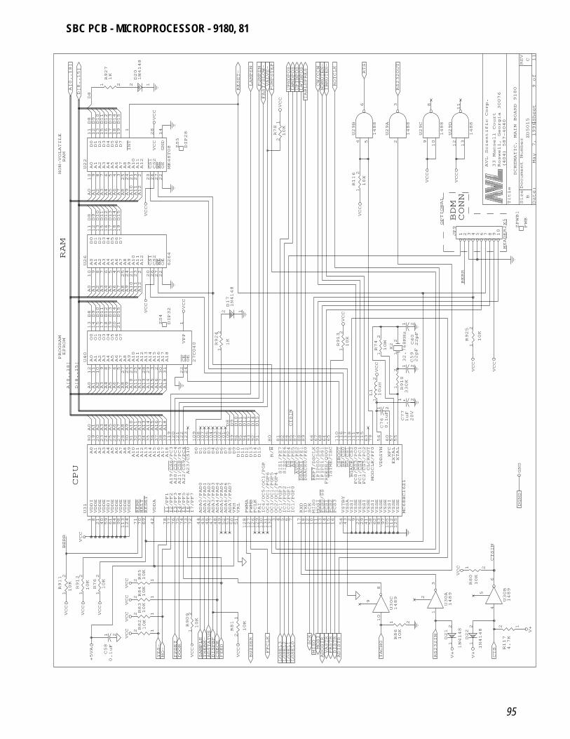
95
Date: May 7, 1996Sheet 9of 11
SizeDocument Number
REV
BZD5015
C
Title
SCHEMATIC, MAIN BOARD 9180
(404) 587-4040
Roswell, Georgia 30076
33 Mansell Court
AVL Scientific Corp.
NON-VOLATILE
RAM
A0
10
A1
9
A2
8
A3
7
A4
6
A5
5
A6
4
A7
3
A8
25
A9
24
A10
21
A11
23
A12
2
CS1
20
CS2
26
WE
27
OE
22
D0
11
D1
12
D2
13
D3
15
D4
16
D5
17
D6
18
D7
19
GND
14
VCC
28
INT
1
U22
MK48T08
1 2
R927
1K
2 1
D20
1N4148
D[8..15]
A[0..18]
D10
D11
D12
D13
D14
D15
A0
A12
A1A2A3A4A5A6A7A8A9A10
A11
D8D9
D8
VCC
VCC
RAM
PROGRAM
EPROM
A0
10
A1
9
A2
8
A3
7
A4
6
A5
5
A6
4
A7
3
A8
25
A9
24
A10
21
A11
23
A12
2
CS1
20
CS2
26
WE
27
OE
22
D0
11
D1
12
D2
13
D3
15
D4
16
D5
17
D6
18
D7
19
U26
6264
ZS4
DIP32
D11
D12
D13
D14
A0
A12
A1A2A3A4A5A6A7A8A9A10
A11
D8D9D10
D11
D12
D13
D14
D15
D8D9D10
D15
VCC
CPU
A0
12
A1
11
A2
10
A3
9
A4
8
A5
7
A6
6
A7
5
A8
27
A9
26
A10
23
A11
25
A12
4
A13
28
A14
29
A15
3
CE
22
OE
24
O0
13
O1
14
O2
15
O3
17
O4
18
O5
19
O6
20
O7
21
A16
2
A17
30
A18
31
VPP
1
U40
27C040
A0
A12
A1A2A3A4A5A6A7A8A9A10
A11
A8A9A10
A11
A12
A13
A14
A15
D[8..15]
A13
A14
A15
A0A1A2A3A4A5A6A7
A16
A17
A18
A16
A17
A18
A[0..18]
12R82
10K
12 R84
10K
12R83
10K
12 R85
10K
VDDI
1
VDDE
8
VDDE
21
VDDE
40
VDDI
59
VDDE
61
VDDE
84
VDDE
98
VDDE
113
VDDE
124
BERR
71
HALT
70
RESET
69
VDDA
42
I1/PF1
78
I2/PF2
77
I3/PF3
76
I4/PF4
75
I5/PF5
74
I6/PF6
73
I7/PF7
72
ADA0/PAD0
44
ADA1/PAD1
45
ADA2/PAD2
46
ADA3/PAD3
47
ADA4/PAD4
48
ADA5/PAD5
49
ADA6/PAD6
52
ADA7/PAD7
53
VRH
50
VRL
51
PWMA
128
PWMB
127
PCLK
126
PAI
129
OC2/OC1/PGP4
3
OC3/OC1/PGP5
132
OC4/OC1/PGP6
131
IC4/OC5/OC1/PGP
130
RXD
17
TXD
18
IC3/PGP2
5
IC2/PGP1
6
IC1/PGP0
7
SCK
12
MISO
10
MOSI
11
PCS0/SS
13
PCS1
14
PCS2
15
PCS3
16
VSTBY
54
VSSA
43
VSSI
2
VSSE
9
VSSE
22
VSSI
29
VSSE
41
VSSI
58
VSSE
62
VSSE
83
VSSE
97
VSSI
105
VSSE
112
VSSE
125
A0
90
A1
19
A2
20
A3
23
A4
24
A5
25
A6
26
A7
27
A8
28
A9
30
A10
31
A11
32
A12
33
A13
34
A14
35
A15
36
A16
37
A17
38
A18
39
A19/CS6/PC3
119
A20/CS7/PC4
120
A21/CS8/PC5
121
A22/CS9/PC6
122
A23/CS10
123
D0
109
D1
108
D2
107
D3
106
D4
104
D5
103
D6
102
D7
101
D8
100
D9
99
D10
96
D11
95
D12
94
D13
93
D14
92
D15
91
AS/PE5
85
DS/PE4
86
R/W
80
DSACK0/PE0
89
DSACK1/PE1
88
SIZ0/PE6
82
SIZ1/PE7
81
AVEC/PE2
87
BKPT/DSCLK
66
IPIPE0/DS0
67
IPIPE1/DS1
68
FREEZE/QUOT
64
TSTME/TSC
65
CSBOOT
110
BR/CS0
116
BG/CS1
117
BGACK/CS2
118
FC0/CS3/PC0
111
FC1/CS4/PC1
114
FC2/CS5/PC2
115
CLCKOUT
63
VDDSYN
56
XFC
60
EXTAL
57
XTAL
55
MODCLK/PF0
79
OC1/PGP3
4
U31
MC68HC16Z1
1
2R76
10K
1
2R911
10K
1
2R912
10K
1 2
C58
0.1uF
YES-
NO-
BERR
VCC
VCC
VCC
VCC
VCC
+5VA
VCC
VCC
VCC
1 2R81
10K
1
2R909
10K
SAMPLE
DOOR
FEED
CHECK
ADSTATUS
DISPBF
THERM-
LGSEL3
LGSEL2
LGSEL1
FPDET
FPCLK
LGSEL0
BUZZER
VCC
VCC
D8D9D10
D11
D12
D13
D14
D15
CTSIN
2 1
D17
1N4148
1
2R924
1K
VCC
ZS5
DIP28
1 2R78
10K
PUMPSTEP
RESET-
VALVE-
FAST/SLOW-
LAMPEN
LWNDPOS
PUMPEN
UPNDPOS
VCC
1
2R116
10K
2
3
U29A
1488
4
5
6
U29B
1488
RS232OUT
RTS
CW/CCW
ROTCLK
TABLEPRES
UPTBPOS
LWTBPOS
NDMOTEN-
TBMOTEN-
VCC
1
2X2
32.768KHz
1
2R74
10M
1 2C60
22pF
1
2R913
10K
VCC
1 2C59
22pF
1
2
R910
330K
1
2L1
10uH
1 2C76
0.1uF
1 2
C77
1uF
20V
VCC
10
8
9
U30C
1489
1 2
R86
10K
DISTR
VASTR
ADOSTR
PRSTR
MOSI
SCK
MISO
TACHO
ADISTR
1
3
2
U30A
1489
4
6
5
U30B
1489
12R117
4.7K
1 2
R80
10K
2 1D21
1N4148
2 1D22
1N4148
RS232IN
CTS
CTSIN
VCC
V+
V+
V+
DGND
GND
BDM
CONN
OPTIONAL
ZPWB1
PWB
1 2 3 4 5 6 7 8 9 10
JP9
HEADER2X5
1
2R925
10K
BERR
VCC
VCC
9
10
8
U29C
1488
12
13
11
U29D
1488
VCC
VCC
SBC PCB - MICROPROCESSOR - 9180, 81
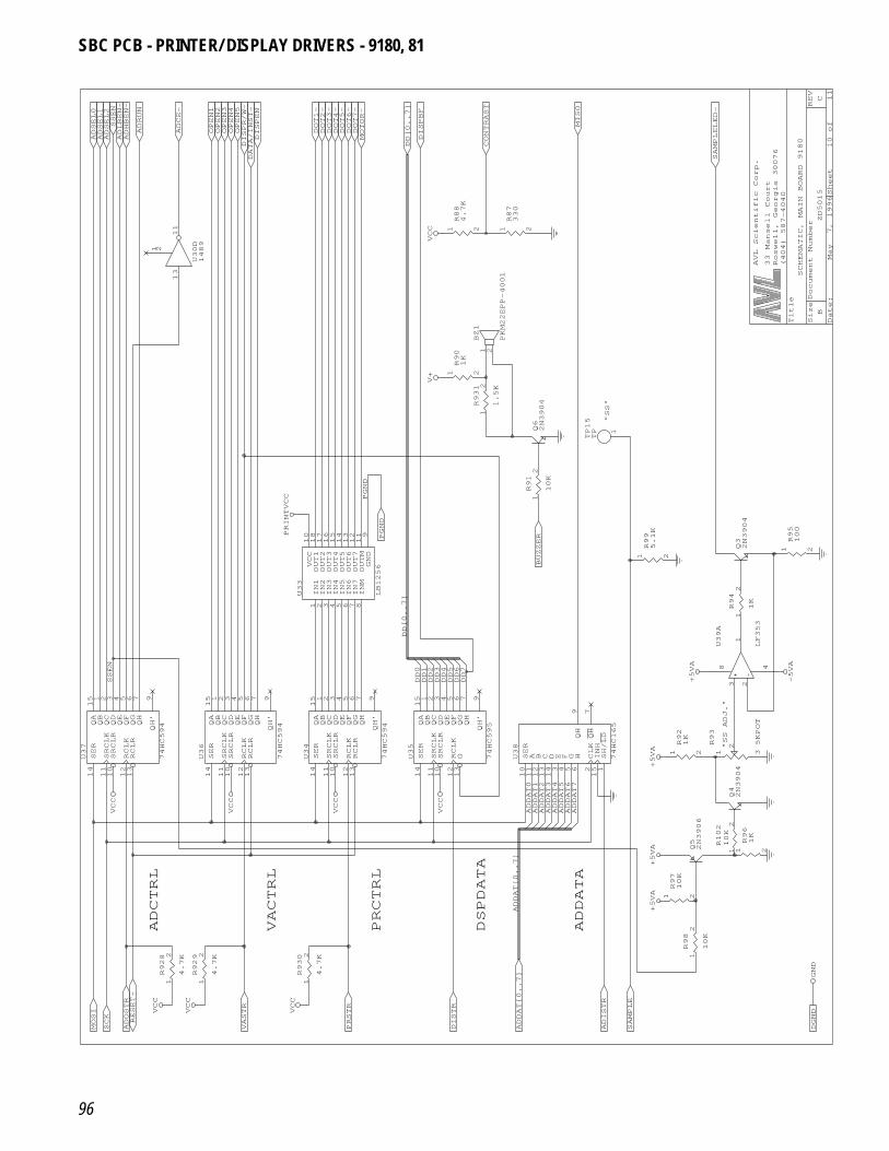
96
Date: May 7, 1996Sheet 10of 11
SizeDocument Number
REV
BZD5015
C
Title
SCHEMATIC, MAIN BOARD 9180
(404) 587-4040
Roswell, Georgia 30076
33 Mansell Court
AVL Scientific Corp.
13
11
1 2
U30D
1489
OPEN1
OPEN2
OPEN3
OPEN4
OPEN5
DATA/INST-
DISPEN
ADSEL0
ADSEL1
ADSEL2
ADRUN
ADCE-
ADHBEN-
ADLBEN-
DISPR/W-
SSEN
SER
14
SRCLK
11
SRCLR
10
RCLK
12
RCLR
13
QA
15
QB
1
QC
2
QD
3
QE
4
QF
5
QG
6
QH
7
QH’
9
U36
74HC594
SER
14
SRCLK
11
SRCLR
10
RCLK
12
RCLR
13
QA
15
QB
1
QC
2
QD
3
QE
4
QF
5
QG
6
QH
7
QH’
9
U37
74HC594
SSEN
VCC
VCC
ADCTRL
1
2R928
4.7K
1
2R929
4.7K
MOSI
SCK
RESET-
VASTR
ADOSTR
VCC
VCC
VACTRL
PRCTRL
1
2R930
4.7K
PRSTR
DISTR
VCC
VCC
10
OUT1
18
OUT2
17
OUT3
16
OUT4
15
OUT5
14
OUT6
13
OUT7
12
OUTM
11
GND
9
IN1
1
IN2
2
IN3
3
IN4
4
IN5
5
IN6
6
IN7
7
INM
8
U33
LB1256
SER
14
SRCLK
11
SRCLR
10
RCLK
12
RCLR
13
QA
15
QB
1
QC
2
QD
3
QE
4
QF
5
QG
6
QH
7
QH’
9
U34
74HC594
SER
14
SRCLK
11
SRCLR
10
RCLK
12
G 13
QA
15
QB
1
QC
2
QD
3
QE
4
QF
5
QG
6
QH
7
QH’
9
U35
74HC595
DD0
DD1
DD2
DD3
DD4
DD5
DD[0..7]
VCC
VCC
1 2
R90
1K
PGND
PGND
PRINTVCC
V+
1 2
R88
4.7K
DOT1-
DOT2-
DOT3-
DOT4-
DOT5-
DOT6-
DOT7-
MOTOR-
DD[0..7]
DISPBF
VCC 1 2
R87
330
MISO
CONTRAST
"SS"
1
2R91
10K
Q62N3904
1 2
R99
5.1K
1
2
BZ1
PKM22EPP-4001
1
2R931
1.5K
BUZZER
1
TP15
TP
SER
10
A 11
B 12
C 13
D 14
E 3
F 4
G 5
H 6
CLK
2
INH
15
SH/LD
1
QH
9
QH
7
U38
74HC165
DD6
DD7
DSPDATA
ADDATA
ADISTR
ADDAT[0..7]
SAMPLE
ADDAT[0..7]
ADDAT0
ADDAT1
ADDAT2
ADDAT3
ADDAT4
ADDAT5
ADDAT6
ADDAT7
Q42N3904
Q52N3906
1 2
R97
10K
1
2R98
10K
1
2
R102
10K
1 2
R96
1K
DGND
+5VA
+5VA
GND
"SS ADJ." 3
2
1
8 4
U39A
LF353
1 2
R92
1K
1 3
2R93
5KPOT
1
2R94
1K
+5VA
+5VA
-5VA
Q32N3904
1 2
R95
100
SAMPLELED-
SBC PCB - PRINTER/ DISPLAY DRIVERS - 9180, 81
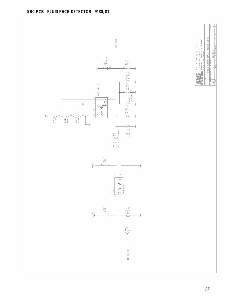
97
Date: May 7, 1996Sheet 11of 11
SizeDocument Number
REV
BZD5015
C
Title
SCHEMATIC, MAIN BOARD 9180
(404) 587-4040
Roswell, Georgia 30076
33 Mansell Court
AVL Scientific Corp.
1 2
R919
620
1 2
R920
3.3K
V+
1 2
R915
160
VCC
2
1
3
4
ISO1
OPB712
1 2
R917
200
VCC
18
23
456
7
U41
LM2907N-8
1 2
R918
3.9K
1
2C80
0.01uF
1
2R922
4.3K
V+
21D18
1N4148
FPDET
VCC
1 2C79
1.0uF
1 2
R921
3.0K
1 2C78
1000pF
1 2C81
0.01uF
1 2
R916
160K
1 2
R923
4.3K
1
2R914
1K
Q14
2N3904
FPCLK
SBC PCB - FLUID PACK DETECTOR - 9180, 81
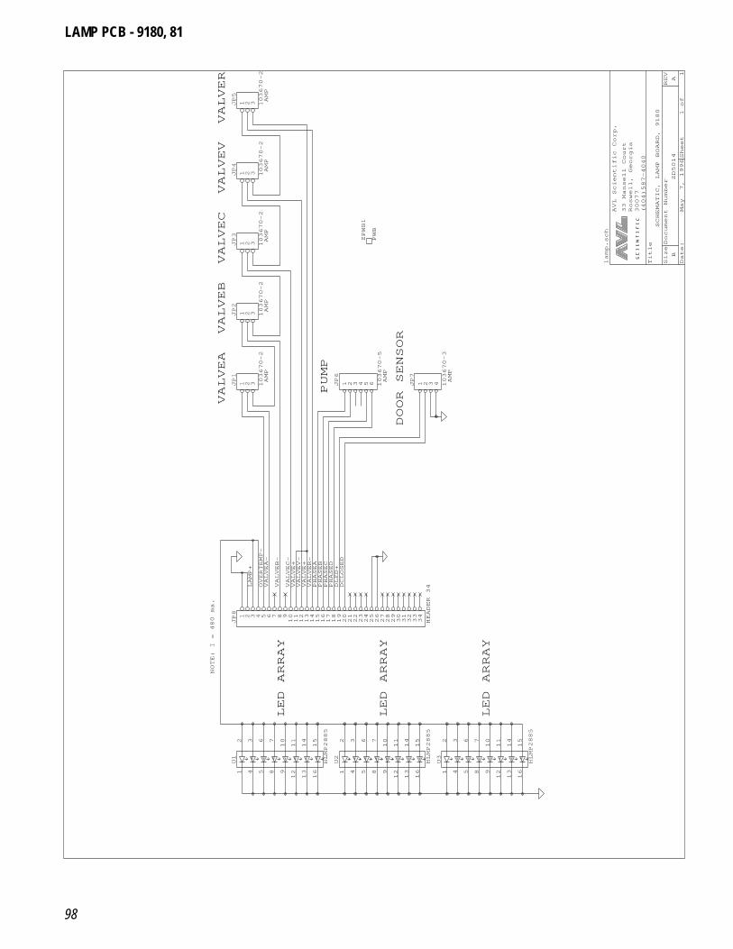
98
Date: May 7, 1996Sheet 1of 1
SizeDocument Number
REV
BZD5014
A
Title
SCHEMATIC, LAMP BOARD, 9180
(404)587-4040
30077
Roswell, Georgia
33 Mansell Court
AVL Scientific Corp.
NOTE: I = 480 ma.
LED ARRAY
2
3
6
7
10
11
14
15
1
4
5
8
9
12
13
16
U1
HLMP2885
2
3
6
7
10
11
14
15
1
4
5
8
9
12
13
16
U2
HLMP2885
VALVEA-
VALVEB-
VALVEC-
VALVEV-
VALVER-
PHASEA
PHASEB
PHASEC
PHASED
DLED+
LAMP+
DCLOSED
VALVE+
VALVE+
OVERTEMP-
1 2 3 4 5 6 7 8 910111213141516171819202122232425262728293031323334
JP8
HEADER 34
VALVEA
VALVEB
PUMP
AMP
AMP
1 2 3 4 5 6JP6
103670-5
1 2 3JP1
103670-2
1 2 3JP2
103670-2
VALVEC
VALVEV
VALVER
AMP
AMP
AMP
ZPWB1
PWB
1 2 3JP3
103670-2
1 2 3JP4
103670-2
1 2 3JP5
103670-2
DOOR SENSOR
AMP
AMP
1 2 3 4JP7
103670-3
LED ARRAY
LED ARRAY
2
3
6
7
10
11
14
15
1
4
5
8
9
12
13
16
U3
HLMP2885
lamp.sch
LAMP PCB - 9180, 81
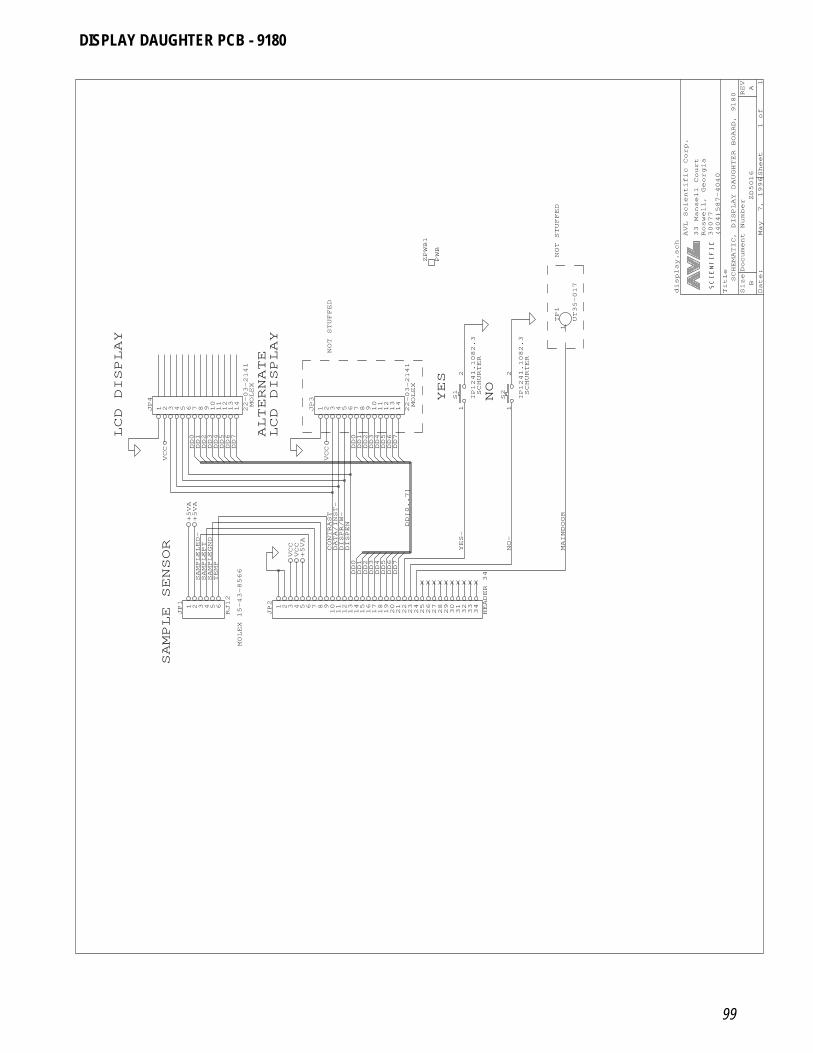
99
Date: May 7, 1996Sheet 1of 1
SizeDocument Number
REV
BZD5016
A
Title
SCHEMATIC, DISPLAY DAUGHTER BOARD, 9180
(404)587-4040
30077
Roswell, Georgia
33 Mansell Court
AVL Scientific Corp.
LCD DISPLAY
1 2 3 4 5 6 7 8 9 1011121314
JP4
22-03-2141
DD0
DD1
DD2
DD3
DD4
DD5
DD6
DD7
VCC
SAMPLE SENSOR
MOLEX 15-43-8566
1 2 3 4 5 6
JP1
RJ12
SAMPLELED-
SAMPLEPT
TEMP
SAMPLEGND
+5VA
+5VA
DD0
DD1
DD2
DD3
DD4
DD5
DD6
DD7
DD[0..7]
DISPEN
DISPR/W-
DATA/INST-
CONTRAST
VCC
VCC
+5VA
1 2 3 4 5 6 7 8 910111213141516171819202122232425262728293031323334
JP2
HEADER 34
LCD DISPLAY
MOLEX
MOLEX
ALTERNATE
NOT STUFFED
1 2 3 4 5 6 7 8 9 1011121314
JP3
22-03-2141
DD0
DD1
DD2
DD3
DD4
DD5
DD6
DD7
VCC
NOT STUFFED
ZPWB1
PWB
YES
NOSCHURTER
SCHURTER
1TP1
UT35-017
1
2
S2
IP1241.1082.3
1
2
S1
IP1241.1082.3
YES-
NO-
MAINDOOR
display.sch
DISPLAY DAUGHTER PCB - 9180

100
8 Parts List
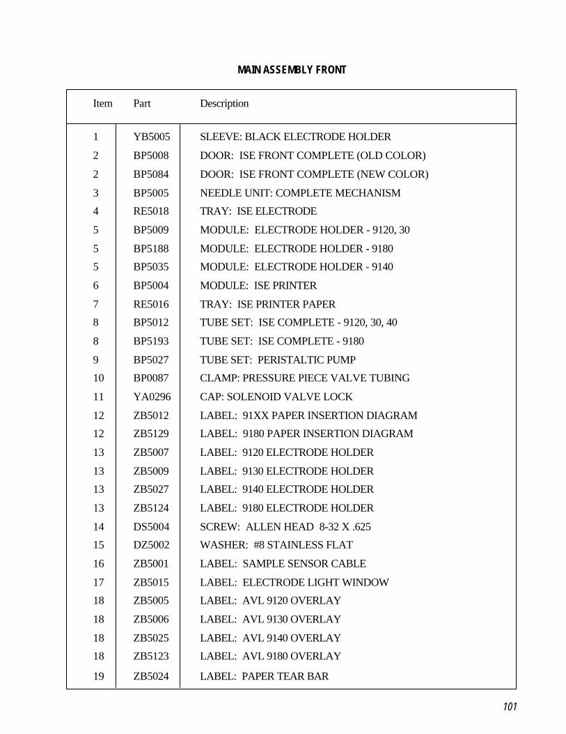
101
MAIN ASSEMBLY FRONT
Item Part Description
1 YB5005 SLEEVE: BLACK ELECTRODE HOLDER
2 BP5008 DOOR: ISE FRONT COMPLETE (OLD COLOR)
2 BP5084 DOOR: ISE FRONT COMPLETE (NEW COLOR)
3 BP5005 NEEDLE UNIT: COMPLETE MECHANISM
4 RE5018 TRAY: ISE ELECTRODE
5 BP5009 MODULE: ELECTRODE HOLDER - 9120, 30
5 BP5188 MODULE: ELECTRODE HOLDER - 9180
5 BP5035 MODULE: ELECTRODE HOLDER - 9140
6 BP5004 MODULE: ISE PRINTER
7 RE5016 TRAY: ISE PRINTER PAPER
8 BP5012 TUBE SET: ISE COMPLETE - 9120, 30, 40
8 BP5193 TUBE SET: ISE COMPLETE - 9180
9 BP5027 TUBE SET: PERISTALTIC PUMP
10 BP0087 CLAMP: PRESSURE PIECE VALVE TUBING
11 YA0296 CAP: SOLENOID VALVE LOCK
12 ZB5012 LABEL: 91XX PAPER INSERTION DIAGRAM
12 ZB5129 LABEL: 9180 PAPER INSERTION DIAGRAM
13 ZB5007 LABEL: 9120 ELECTRODE HOLDER
13 ZB5009 LABEL: 9130 ELECTRODE HOLDER
13 ZB5027 LABEL: 9140 ELECTRODE HOLDER
13 ZB5124 LABEL: 9180 ELECTRODE HOLDER
14 DS5004 SCREW: ALLEN HEAD 8-32 X .625
15 DZ5002 WASHER: #8 STAINLESS FLAT
16 ZB5001 LABEL: SAMPLE SENSOR CABLE
17 ZB5015 LABEL: ELECTRODE LIGHT WINDOW
18 ZB5005 LABEL: AVL 9120 OVERLAY
18 ZB5006 LABEL: AVL 9130 OVERLAY
18 ZB5025 LABEL: AVL 9140 OVERLAY
18 ZB5123 LABEL: AVL 9180 OVERLAY
19 ZB5024 LABEL: PAPER TEAR BAR
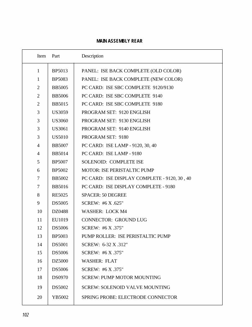
102
MAIN ASSEMBLY REAR
Item Part Description
1 BP5013 PANEL: ISE BACK COMPLETE (OLD COLOR)
1 BP5083 PANEL: ISE BACK COMPLETE (NEW COLOR)
2 BB5005 PC CARD: ISE SBC COMPLETE 9120/9130
2 BB5006 PC CARD: ISE SBC COMPLETE 9140
2 BB5015 PC CARD: ISE SBC COMPLETE 9180
3 US3059 PROGRAM SET: 9120 ENGLISH
3 US3060 PROGRAM SET: 9130 ENGLISH
3 US3061 PROGRAM SET: 9140 ENGLISH
3 US5010 PROGRAM SET: 9180
4 BB5007 PC CARD: ISE LAMP - 9120, 30, 40
4 BB5014 PC CARD: ISE LAMP - 9180
5 BP5007 SOLENOID: COMPLETE ISE
6 BP5002 MOTOR: ISE PERISTALTIC PUMP
7 BB5002 PC CARD: ISE DISPLAY COMPLETE - 9120, 30 , 40
7 BB5016 PC CARD: ISE DISPLAY COMPLETE - 9180
8 RE5025 SPACER: 50 DEGREE
9 DS5005 SCREW: #6 X .625"
10 DZ0488 WASHER: LOCK M4
11 EU1019 CONNECTOR: GROUND LUG
12 DS5006 SCREW: #6 X .375"
13 BP5003 PUMP ROLLER: ISE PERISTALTIC PUMP
14 DS5001 SCREW: 6-32 X .312"
15 DS5006 SCREW: #6 X .375"
16 DZ5000 WASHER: FLAT
17 DS5006 SCREW: #6 X .375"
18 DS0970 SCREW: PUMP MOTOR MOUNTING
19 DS5002 SCREW: SOLENOID VALVE MOUNTING
20 YB5002 SPRING PROBE: ELECTRODE CONNECTOR

103
ELECTRODE HOLDER ASSEMBLY
Item Part Description
0 BP5009 MODULE: ELECTRODE HOLDER COMPLETE ASSEMBLY9120/9130
0 BP5035 MODULE: ELECTRODE HOLDER COMPLETE ASSEMBLY9140
0 BP5188 MODULE: ELECTRODE HOLDER COMPLETE ASSEMBLY9180
1 BP0171 ELECTRODE HOLDER: LEFT SIDE ASSEMBLY
2 BP5010 HOLDER: ISE RIGHT ELECTRODE 9120/9130
2 BP5036 HOLDER: ISE RIGHT ELECTRODE 9140/80
3 RE5019 HOLDER: BASE ISE ELECTRODE
4 DS0970 SCREW: PHILLIPS M4x16
5 DA0156 O-RING: ELECTRODE SEAL
6 ZB5007 LABEL: 9120 ELECTRODE HOLDER
6 ZB5009 LABEL: 9130 ELECTRODE HOLDER
6 ZB5027 LABEL: 9140 ELECTRODE HOLDER
6 ZB5124 LABEL: 9180 ELECTRODE HOLDER
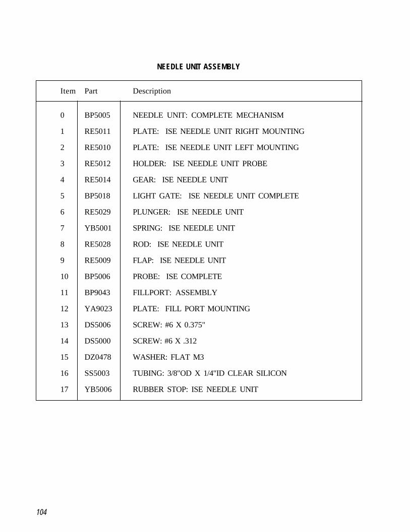
104
NEEDLE UNIT ASSEMBLY
Item Part Description
0 BP5005 NEEDLE UNIT: COMPLETE MECHANISM
1 RE5011 PLATE: ISE NEEDLE UNIT RIGHT MOUNTING
2 RE5010 PLATE: ISE NEEDLE UNIT LEFT MOUNTING
3 RE5012 HOLDER: ISE NEEDLE UNIT PROBE
4 RE5014 GEAR: ISE NEEDLE UNIT
5 BP5018 LIGHT GATE: ISE NEEDLE UNIT COMPLETE
6 RE5029 PLUNGER: ISE NEEDLE UNIT
7 YB5001 SPRING: ISE NEEDLE UNIT
8 RE5028 ROD: ISE NEEDLE UNIT
9 RE5009 FLAP: ISE NEEDLE UNIT
10 BP5006 PROBE: ISE COMPLETE
11 BP9043 FILLPORT: ASSEMBLY
12 YA9023 PLATE: FILL PORT MOUNTING
13 DS5006 SCREW: #6 X 0.375"
14 DS5000 SCREW: #6 X .312
15 DZ0478 WASHER: FLAT M3
16 SS5003 TUBING: 3/8"OD X 1/4"ID CLEAR SILICON
17 YB5006 RUBBER STOP: ISE NEEDLE UNIT
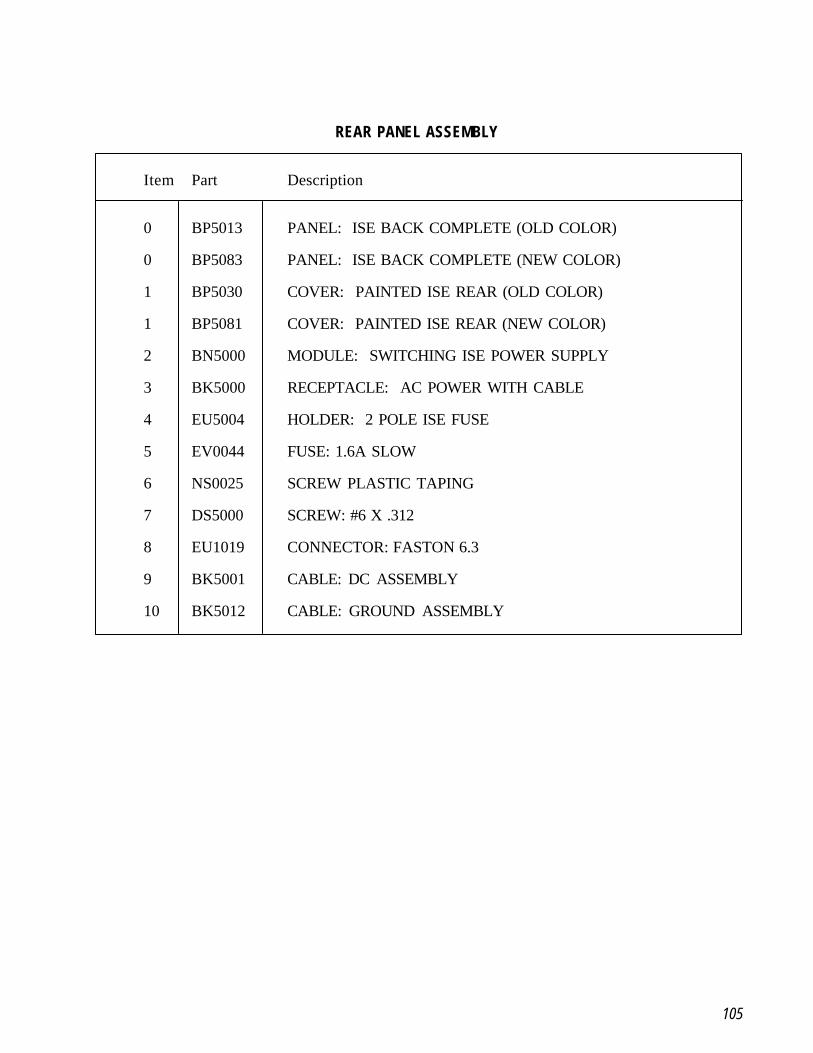
105
REAR PANEL ASSEMBLY
Item Part Description
0 BP5013 PANEL: ISE BACK COMPLETE (OLD COLOR)
0 BP5083 PANEL: ISE BACK COMPLETE (NEW COLOR)
1 BP5030 COVER: PAINTED ISE REAR (OLD COLOR)
1 BP5081 COVER: PAINTED ISE REAR (NEW COLOR)
2 BN5000 MODULE: SWITCHING ISE POWER SUPPLY
3 BK5000 RECEPTACLE: AC POWER WITH CABLE
4 EU5004 HOLDER: 2 POLE ISE FUSE
5 EV0044 FUSE: 1.6A SLOW
6 NS0025 SCREW PLASTIC TAPING
7 DS5000 SCREW: #6 X .312
8 EU1019 CONNECTOR: FASTON 6.3
9 BK5001 CABLE: DC ASSEMBLY
10 BK5012 CABLE: GROUND ASSEMBLY
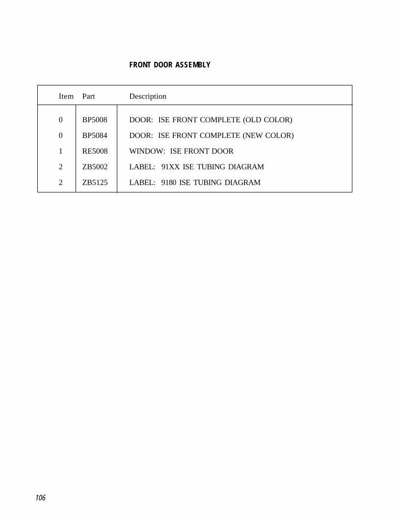
106
FRONT DOOR ASSEMBLY
Item Part Description
0 BP5008 DOOR: ISE FRONT COMPLETE (OLD COLOR)
0 BP5084 DOOR: ISE FRONT COMPLETE (NEW COLOR)
1 RE5008 WINDOW: ISE FRONT DOOR
2 ZB5002 LABEL: 91XX ISE TUBING DIAGRAM
2 ZB5125 LABEL: 9180 ISE TUBING DIAGRAM
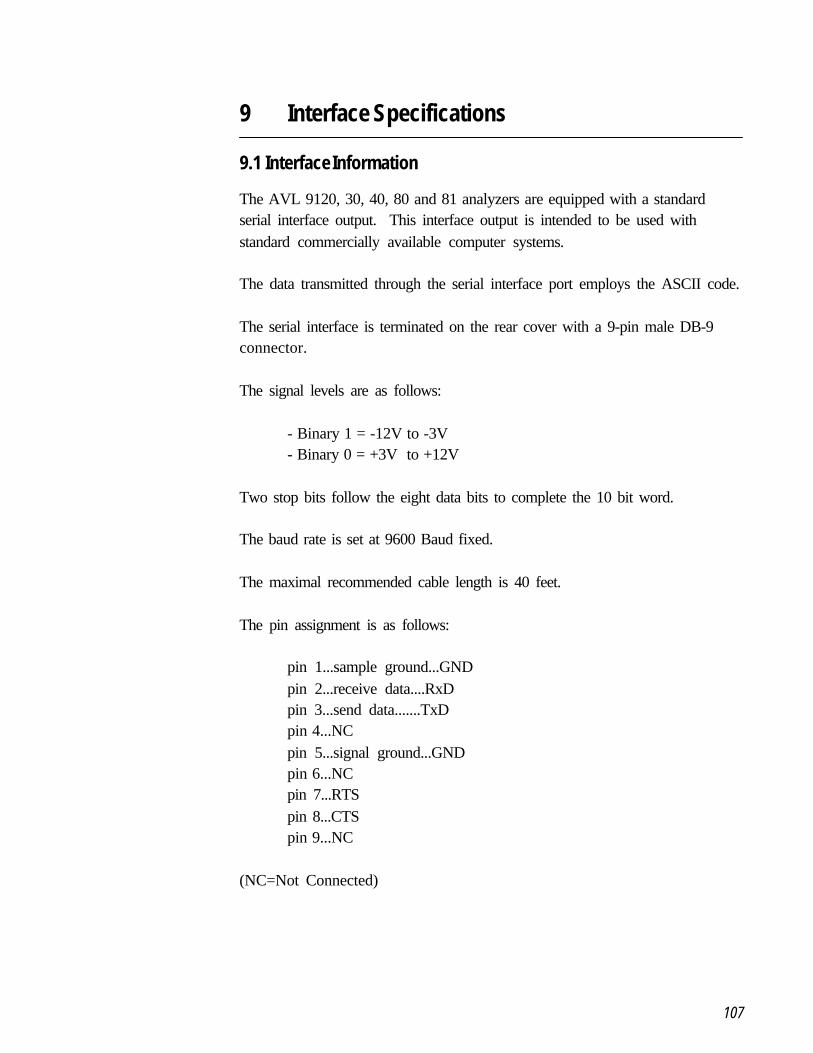
107
9 Interface Specifications
9.1 Interface Information
The AVL 9120, 30, 40, 80 and 81 analyzers are equipped with a standardserial interface output. This interface output is intended to be used withstandard commercially available computer systems.
The data transmitted through the serial interface port employs the ASCII code.
The serial interface is terminated on the rear cover with a 9-pin male DB-9connector.
The signal levels are as follows:
- Binary 1 = -12V to -3V- Binary 0 = +3V to +12V
Two stop bits follow the eight data bits to complete the 10 bit word.
The baud rate is set at 9600 Baud fixed.
The maximal recommended cable length is 40 feet.
The pin assignment is as follows:
pin 1...sample ground...GNDpin 2...receive data....RxDpin 3...send data.......TxDpin 4...NCpin 5...signal ground...GNDpin 6...NCpin 7...RTSpin 8...CTSpin 9...NC
(NC=Not Connected)
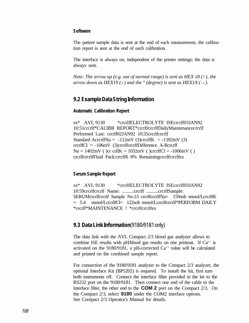
108
Software
The patient sample data is sent at the end of each measurement, the calibra-tion report is sent at the end of each calibration.
The interface is always on, independent of the printer settings; the data isalways sent.
Note: The arrow up (e.g. out of normal range) is sent as HEX 18 (↑), thearrow down as HEX19 (↓) and the ° (degree) is sent as HEX1A (→).
9.2 Example Data String Information
Automatic Calibration Report
sx* AVL 9130 *crcrlfELECTROLYTE ISEcrcrlf03JAN9210:51crcrlf*CALIBR REPORT*crcrlfcrcrlfDailyMaintenancecrcrlfPerformed Last: crcrlf02JAN92 10:35crcrlfcrcrlfStandard AcrcrlfNa = -112mV (3)crcrlfK = -1392mV (3)crcrlfCl = -106mV (3)crcrlfcrcrlfDifference A-BcrcrlfNa = 1402mV ( )cr crlfK = 1032mV ( )crcrlfCl = -1006mV ( )crcrlfcrcrlfFluid Pack:crcrlf6 8% Remainingcrcrlfcrcrlfex
Serum Sample Report
sx* AVL 9130 *crcrlfELECTROLYTE ISEcrcrlf03JAN9210:59crcrlfcrcrlf Name: ..........crcrlf ..........crcrlfSample:SERUMcrcrlfcrcrlf Sample No.13 crcrlfcrcrlfNa= 159soh mmol/LcrcrlfK= 5.4 mmol/LcrcrlfCl= 122soh mmol/Lcrcrlfcrcrlf*PERFORM DAILY*crcrlf*MAINTENANCE ! *crcrlfcrcrlfex
9.3 Data Link Information (9180/9181 only)
The data link with the AVL Compact 2/3 blood gas analyzer allows tocombine ISE results with pH/blood gas results on one printout. If Ca++ isactivated on the 9180/9181, a pH-corrected Ca++ value will be calculatedand printed on the combined sample report.
For connection of the 9180/9181 analyzer to the Compact 2/3 analyzer, theoptional Interface Kit (BP5202) is required. To install the kit, first turnboth instruments off. Connect the interface filter provided in the kit to theRS232 port on the 9180/9181. Then connect one end of the cable to theinterface filter, the other end to the COM 2 port on the Compact 2/3. Onthe Compact 2/3, select 9180 under the COM2 interface options.See Compact 2/3 Operator's Manual for details.