roller rail systems - nimble motionnimblemotion.co.in/brochures/roller-rail_re82301_0397.pdf ·...
TRANSCRIPT
1RE 82 301/03.97
RE 82 301/03.97
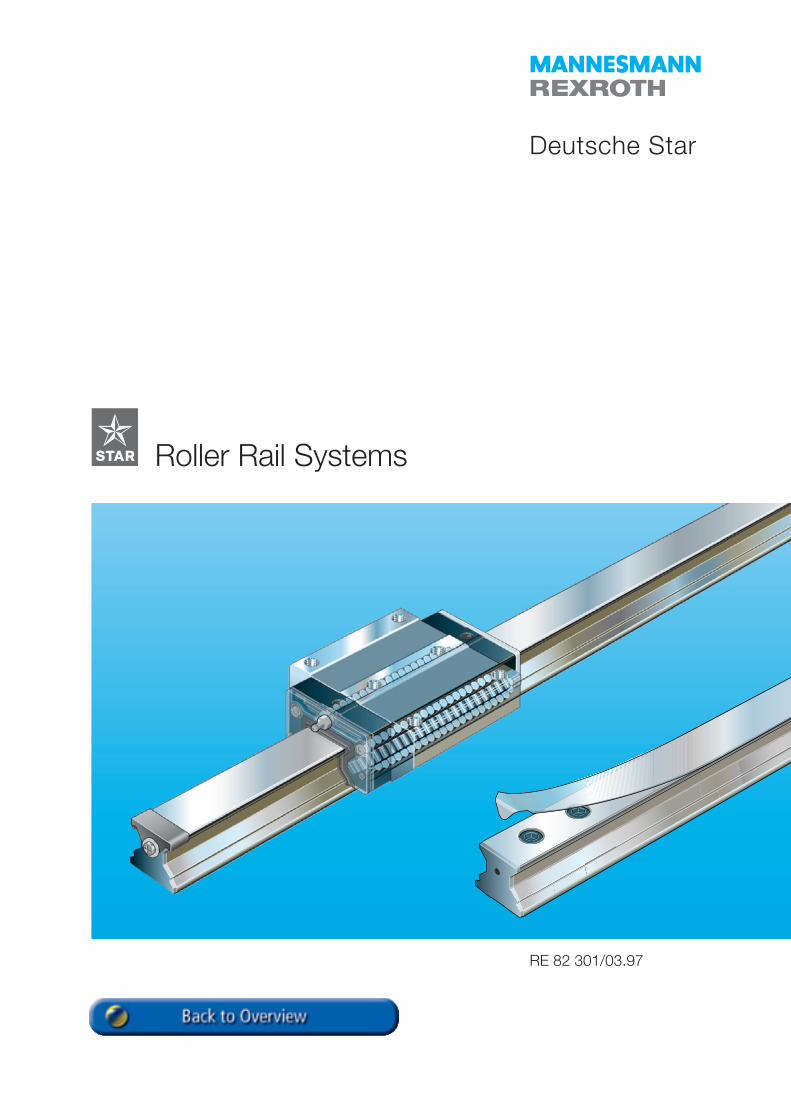
Roller Rail Systems
Deutsche Star
STAR – Roller Rail Systems
2 RE 82 301/03.97
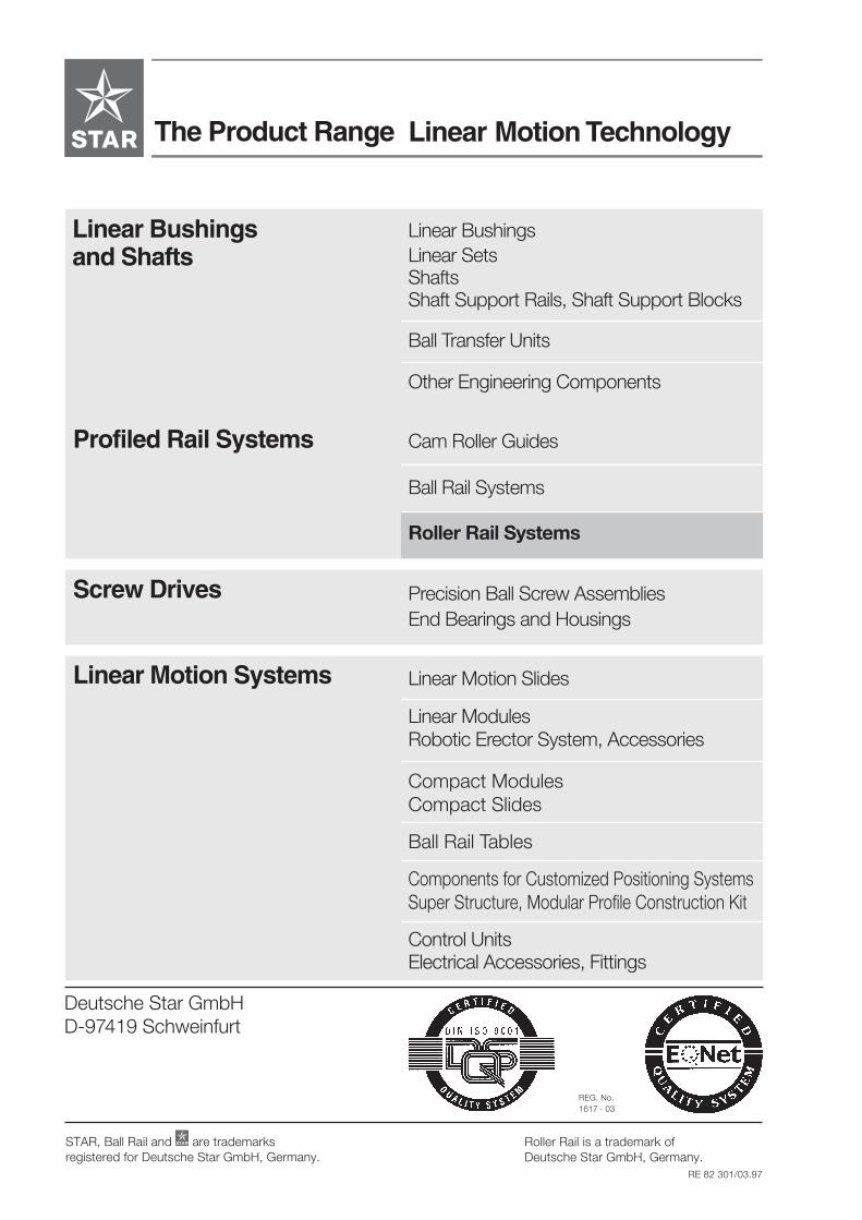
The Product Range Linear Motion Technology
Linear BushingsLinear SetsShaftsShaft Support Rails, Shaft Support Blocks
Ball Transfer Units
Other Engineering Components
Profiled Rail Systems Cam Roller Guides
Ball Rail Systems
Roller Rail Systems
Screw Drives Precision Ball Screw AssembliesEnd Bearings and Housings
Linear Motion Systems Linear Motion Slides
Linear ModulesRobotic Erector System, Accessories
Compact ModulesCompact Slides
Ball Rail Tables
Components for Customized Positioning SystemsSuper Structure, Modular Profile Construction Kit
Control UnitsElectrical Accessories, Fittings
Deutsche Star GmbHD-97419 Schweinfurt
REG. No.1617 - 03
Roller Rail is a trademark ofDeutsche Star GmbH, Germany.
STAR, Ball Rail and are trademarksregistered for Deutsche Star GmbH, Germany.
Linear Bushingsand Shafts
3RE 82 301/03.97
Product Overview 4
Product Description 8
Technical Data 9
Calculations 12
Mounting Instructions 14
Runner Blocks – Part numbers, Dimensions 22
Guide Rails – Part numbers, Dimensions 30
Rail Seal Cover Strip, Mounting Hole Plugs, Protective Caps 36
Accessories 38
Mounting Instructions, Bellows 45
Maintenance and Lubrication 46
Roller Rail Systems
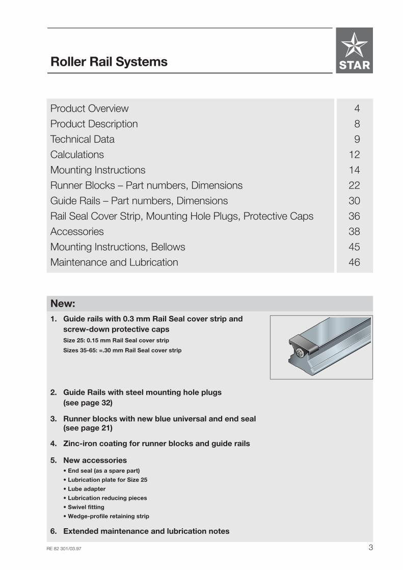
New:1. Guide rails with 0.3 mm Rail Seal cover strip and
screw-down protective capsSize 25: 0.15 mm Rail Seal cover strip
Sizes 35-65: =.30 mm Rail Seal cover strip
2. Guide Rails with steel mounting hole plugs(see page 32)
3. Runner blocks with new blue universal and end seal(see page 21)
4. Zinc-iron coating for runner blocks and guide rails
5. New accessories• End seal (as a spare part)
• Lubrication plate for Size 25
• Lube adapter
• Lubrication reducing pieces
• Swivel fitting
• Wedge-profile retaining strip
6. Extended maintenance and lubrication notes
STAR – Roller Rail Systems
4 RE 82 301/03.97
STAR
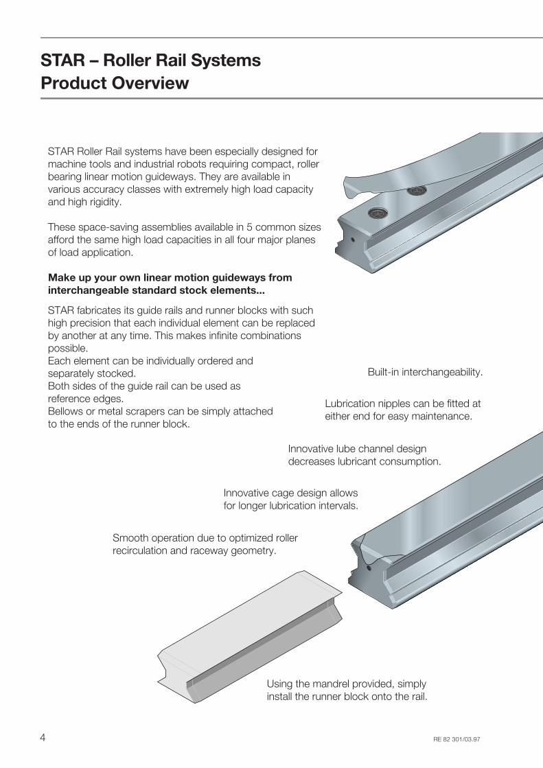
STAR Roller Rail systems have been especially designed formachine tools and industrial robots requiring compact, rollerbearing linear motion guideways. They are available invarious accuracy classes with extremely high load capacityand high rigidity.
These space-saving assemblies available in 5 common sizesafford the same high load capacities in all four major planesof load application.
Make up your own linear motion guideways frominterchangeable standard stock elements...
STAR fabricates its guide rails and runner blocks with suchhigh precision that each individual element can be replacedby another at any time. This makes infinite combinationspossible.Each element can be individually ordered andseparately stocked.Both sides of the guide rail can be used asreference edges.Bellows or metal scrapers can be simply attachedto the ends of the runner block.
Product Overview
Using the mandrel provided, simplyinstall the runner block onto the rail.
Innovative lube channel designdecreases lubricant consumption.
Lubrication nipples can be fitted ateither end for easy maintenance.
Built-in interchangeability.
Smooth operation due to optimized rollerrecirculation and raceway geometry.
Innovative cage design allowsfor longer lubrication intervals.

5RE 82 301/03.97
STAR
Optimum rigidity under loadfrom all directions.
Proven Rail Seal cover strip for guide railmounting holes:
• A single cover for all holes
• Made of corrosion resistant spring steelto DIN 17230 / EN 10088
• Easy, secure clip-on fitting
Mounting of attachments to runnerblock from above or below.
Improved rigidity under lift-off andside loading conditions when additio-nal mounting screws are used in thetwo holes provided at the center ofthe runner block.
Guide rails and runner blocks inaccuracy class H (preload 0.03 C)also available with surface protection.
End seal as standard.
Integral all-round sealing.
Optimized entry-section geometry andhigh number of rollers per track greatlyreduce any variation in elastic deflection.
High moment capacityabout all axes.

STAR – Roller Rail Systems
6 RE 82 301/03.97
Product Overview
Standard width1851-
Runner blocks
Standard widthlong
1853-
Slimline high1821-
Slimline highlong
1824-
Guide rail30
28
26
22
24
Page
34
38
Accessories- Scraper plate- End seal- Lubrication plate- Lube adapter- Lubrication reducing pieces- Wedge-profile retaining strip- Bellows
Scraper plate
1805-
For mountingfrom above
1807-
For mountingfrom below
STAR
STAR
STAR
STAR
CC0
C
C0
C
C0
CC0
C
C0
C
C0
STAR
STAR
CC0
C
C0
C
C0
CC0
C
C0
C
C0
STAR
STAR
STAR
STAR
- Rail Seal with protective caps- Mounting hole plugs
(mounting jig for steel mountinghole plugs)
36
STAR
STAR
End seal
(Special version: zinc-iron coating)
(Special version: zinc-iron coating)
Special version:All runner blocks in accuracy class Hand preload 0.03 C also availablewith zinc-iron coating.
7RE 82 301/03.97
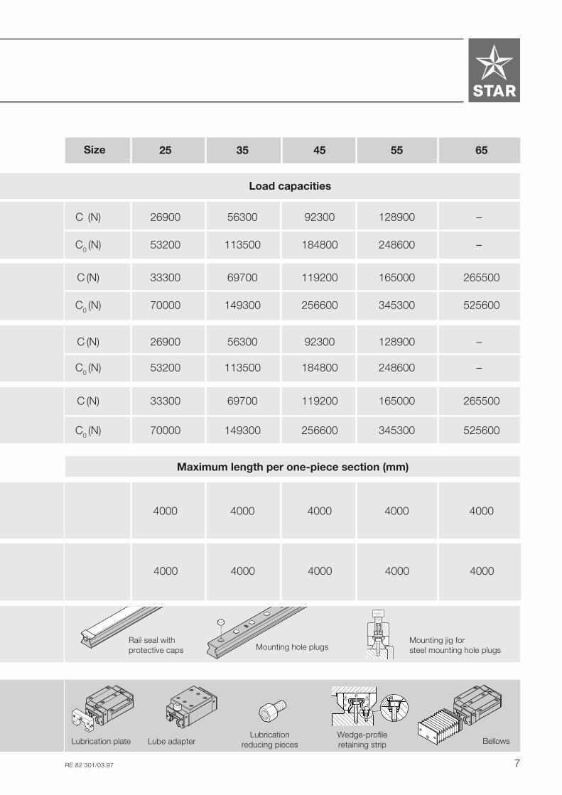
C (N) 26900 56300 92300 128900 –
C0 (N) 53200 113500 184800 248600 –
C0 (N) 70000 149300 256600 345300 525600
C (N) 26900 56300 92300 128900 –
C0 (N) 53200 113500 184800 248600 –
C (N) 33300 69700 119200 165000 265500
C0 (N) 70000 149300 256600 345300 525600
25 35 45 55 65Size
4000 4000 4000 4000 4000
C (N) 33300 69700 119200 165000 265500
Maximum length per one-piece section (mm)
4000 4000 4000 4000 4000
Bellows
STAR
STAR
STAR
STAR
Lubrication plate Lube adapter
STAR
STAR
Mounting jig forsteel mounting hole plugsMounting hole plugs
Rail seal withprotective caps
Load capacities
���Wedge-profileretaining strip
Lubricationreducing pieces
�����

STAR – Roller Rail Systems
8 RE 82 301/03.97
Standard width Slimline high
Product Description
The Roller Rail Systems consist of:
guide rail; all surfaces ground; hardened bearing surfaces
runner block of anti-friction bearing steel, hardened and ground raceways, with:
- rollers made of anti-friction bearing steel- cage designed for optimum roller recirculation- fully sealed roller raceways- two end seals for better sealing and to protect plastic parts.
STST
ARAR
STSTARAR
STSTARAR

9RE 82 301/03.97
1000 2000 3000 4000
10
20
30
0
40
0
50
H
P
SP
UP
For any runner block/railcombination at any positionon rail
For different runner blocksat same position on rail
Mesured atmiddle of
runner block:
Technical Data
Accuracy classes and theirtolerances (µm)
STAR Roller Rail Systems are availablein 4 different accuracy classes.
Rail length (mm)
Accuracy Dimensional Max. difference in dimensionsclasses tolerances (µm) H and A3 on the same guide rail
H A3 ∆ H, ∆ A3 (µm)
UP ± 5 ± 5 3
SP ± 10 ± 7 5
P ± 20 ± 10 7
H ± 40 ± 20 15
Built-in interchangeability due toprecision machining
STAR machines guide rails and runnerblocks, and the roller raceways inparticular, with such high precisionthat each individual element is inter-changeable. Any runner block can becombined with any guide rail of thesame size. It is also possible to installseveral different runner blocks on thesame guide rail.
Parallelism offset P1 ofRoller Rail Systemswhen properly installed
Measured at middle of runner block
Par
alle
lism
offs
et P
1 (µ
m)
A 3
H 1PII
1PII
1PII
STAR
STAR
STAR
STAR
STAR
STAR
STAR
STAR
STAR
STAR
STAR
STAR
STAR – Roller Rail Systems
10 RE 82 301/03.97
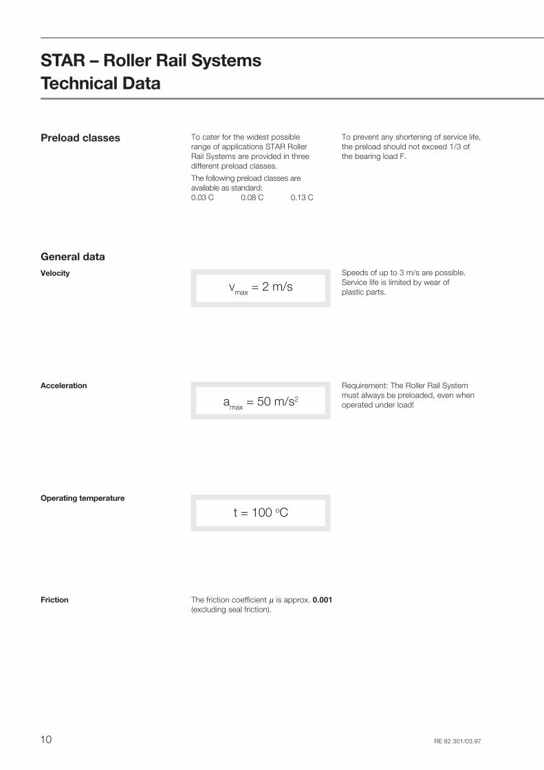
Preload classes To cater for the widest possiblerange of applications STAR RollerRail Systems are provided in threedifferent preload classes.
The following preload classes areavailable as standard:0.03 C 0.08 C 0.13 C
To prevent any shortening of service life,the preload should not exceed 1/3 ofthe bearing load F.
Technical Data
General dataVelocity
vmax = 2 m/s
amax = 50 m/s2
Acceleration Requirement: The Roller Rail Systemmust always be preloaded, even whenoperated under load!
t = 100 oCOperating temperature
The friction coefficient µ is approx. 0.001(excluding seal friction).
Friction
Speeds of up to 3 m/s are possible.Service life is limited by wear ofplastic parts.
11RE 82 301/03.97
10000 20000 30000 40000 50000
10
20
30
0
40
0
50
60000
55
35
2545
65
10000 20000 30000 40000 50000
10
20
30
0
40
0
50
60000
45
55
3525
65
10000 20000 30000 40000 50000
10
20
30
0
40
0
50
60000
55
65
453525
Load F (N)
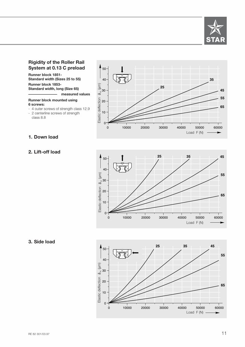
Rigidity of the Roller RailSystem at 0.13 C preloadRunner block 1851-Standard width (Sizes 25 to 55)
Runner block 1853-Standard width, long (Size 65)
measured values
Runner block mounted using6 screws:- 4 outer screws of strength class 12.9- 2 centerline screws of strength
class 8.8
2. Lift-off load
3. Side load
Ela
stic
def
lect
ion
el
. (µm
)
Load F (N)
Load F (N)
1. Down load
Ela
stic
def
lect
ion
el
. (µm
)E
last
ic d
efle
ctio
n
el. (
µm)

STAR – Roller Rail Systems
12 RE 82 301/03.97
Calculations
(2)
(1)
= L2.s.n.60hL
L = ( )CF
3.105
10
Note:The structure of Roller Rail Systemsallows this simplified calculation.
If the bearings are subjected to com-bined loads (vertical and horizontal),calculate the equivalent dynamic load Faccording to formula (6):
Nominal life
- under combined loads
- at constant speeds
Calculate the nominal travel life L or Lhaccording to formula (1), (2) or (3):
L = nominal life (m)Lh = nominal life (h)vm = average speed (m/min)v1, v2...vn = discrete speed steps (m/min)t1, t2...tn = percentage of stroke
covered at v1, v2...vn (%)
(4)
(3) = L.vhL
m60
t1 t 2 t n = mv100
.vn... ++.v2.v1 +
(5) F = . q 1
100F1 + F2
. q 2
100+ ... + Fn
. q n
1003
103
103
103
10
F = equivalent dynamic load (N)F1, F2...Fn = discrete dynamic load steps (N)q1, q2...qn = percentage of stroke covered under F1, F2...Fn (%)
- at varying speeds
F = equivalent dynamic load (N)FV = external dynamic load, vertical (N)FH = external dynamic load,
horizontal (N)
(6) FV FHF = +
NotesIf FV and FH involve several differentload levels, they have to be calculatedseparately using formula (5).An external load acting at an angle onthe runner block is to be broken downinto its FV and FH components and thesevalues then used in formula (6).
Equivalent dynamic loadsfor calculation ofnominal life- under variable loads
If the bearings are subjected to variableloads, calculate the equivalent dynamicload F according to formula (5):
L = nominal life (m)Lh = nominal life (h)C = dynamic load capacity (N)F = equivalent dynamic load (N)s = length of stroke (m)n = stroke repetition rate
(full cycles) (min-1)
FH
FV

13RE 82 301/03.97
NotesIf FV and FH involve several differentload levels, they have to be calculatedseparately using formula (5).An external load acting at an angle onthe runner block is to be broken downinto its FV and FH components and thesevalues then used in formula (7).
- under combined loads incombination with a moment
F = equivalent dynamic load (N)FV, FH = external dynamic loads (N)M = dynamic moment (Nm)C = dynamic load capacity * (N)Mt = permissible dynamic
moment * (Nm)* see load capacity tables
If bearings are subjected to combinedloads (vertical and horizontal) in com-bination with a moment, calculate theequivalent dynamic load F accordingto formula (7):
Formula (7) is only applicable if a singleguide rail is used.
Equivalent static loadon bearing
If bearings are subjected to combinedstatic loads (vertical and horizontal) incombination with a static moment,calculate the equivalent static load F0according to formula (8).
The equivalent static load F0 must notexceed the static load capacity C0.
Formula (8) is only applicable if a singleguide rail is used.
F0 = equivalent static load (N)FV0, FH0 = external static loads (N)M0 = static moment (Nm)C0 = static load capacity * (N)Mt0 = permissible static
moment * (Nm)* see load capacity tables
NotesAn external load acting at an angle on therunner block is to be broken down into itsFV0 and FH0 components and thesevalues then used in formula (8).
(8) CF = + .MM
t0 0
0
0
FV0 FH0+
(7) CF = + .MM
tFV FH
+
FV
FH
M
FV0
FH0
M

STAR – Roller Rail Systems
14 RE 82 301/03.97
Mounting Instructions
Parallelism offset ofmounted rails (tolerance)measured on the guide rails and therunner blocks
The parallelism offset P1 causes a slightrise in the preload on one side.As long as the values specified in thetable are met, the effect of this on theservice life can generally be neglected.
Size Parallelism offset P1 (mm)Preload
0.03 C 0.08 C 0.13 C
25 0.012 0.007 0.00535 0.015 0.010 0.00745 0.019 0.012 0.00955 0.025 0.016 0.01165 0.035 0.022 0.016
1PII
Vertical offsetProvided the vertical offset is keptwithin the stated tolerances for S1and S2, its influence on the servicelife can generally be neglected.
S1= permissible vertical offset (mm)a = distance between guide rails (mm)Y = calculation factor
S1 = a · Y
Permissible vertical offset inlongitudinal direction S2
The permissible vertical offset S2includes the tolerance max. differencein dimension H on the same guide rail,as given in the table on page 9.
S2 = b · 4.3 · 10-5
S2 = b · 3.0 · 10-5
Runner Blocks 1851-, 1821-
Runner Blocks 1853-, 1824-(long version)
S2= permissible vertical offset (mm)
b = distance betweenrunner blocks (mm)
Permissible vertical offset intransverse direction S1
Calculation factor for preload classes
Preload Preload Preload0.02 C 0.08 C 0.13 C
Y 2.8 · 10-4 1.7 · 10-4 1.2 · 10-4
1S
a
b
S2

15RE 82 301/03.97
All steel parts are treated with anti-corrosion oil prior to shipment. It is notnecessary to remove this oil providedthe recommended lubricants are used.
STAR Roller Rail Systems are high-quality,precision manufactured products andmust therefore be handled with theutmost care in transit and during sub-sequent installation.The same care must be taken with RailSeal mounting hole cover strips(see the relevant mounting instructions).
General Notes
The following installation notes apply to allRoller Rail Systems.
Use the plastic mandrel again toremove runner blocks from the rail!When not installed on the guide rails,the runner blocks should always bekept on the plastic mandrel!
Do not remove the plastic mandrelfrom the runner block until the runner issafely on the rail!Otherwise, the rollers may fall out!
Mounting instructionsMounting the guide rails:Guide rail with lateral retention:• If a Rail Seal mounting hole cover
strip is fitted, unclip it. (Observe themounting instructions!)
• Push both rails into contact with thefitting edges (1) and tighten the screwslightly.
• Fix the rails in place with retaining strips(2) or wedge profiles (3).
• Apply the specified torque to tighten theguide rail screws. (see Table, page 18).
• Mount the Rail Seal or the mountinghole plugs (Observe the mountinginstructions!)
Mounting the runner blocks:• Carefully slide the runner block onto
the guide rail.• Press the runner block on the first rail
against the fitting edge (1) andscrew down.
• Screw down the runner block on thesecond rail and pin if required.
Do not drill holes for locating pins untilafter mounting (see also page 19). If thesystem has been properly installed, therunner block should slide easily on the rail.
NoteFor guide rails without lateral retention, werecommend using a straightedge to makesure the rails are properly aligned andparallel during assembly.(See page 16 for permissible side loadsfor rails without additional lateralretention.)
���������������������������������������������������
������������������������������������
����������������
������������
������������
21
���������������������������������������������������
���������������������������������������
������������
3
1
STSTARAR
STSTARAR
STSTARAR
STSTARAR
STSTARAR
STSTARAR
Inserting the mounting hole plugs:• After mounting the guide rails, tap the
rail mounting screw hole plugs (2)into the screw holes with the aid ofa plastic pad (1) until flush with thesurface of the rail.
• Steel mounting hole plugs:Always use the special mounting jig.Equalize the rail surface.
12�����

STAR – Roller Rail Systems
16 RE 82 301/03.97
h1 r1 h2 r2 O1 O22) O4
1)2) O5 O3 O6 N8min. max. max. max. DIN 912 DIN 6912 DIN 912 DIN 912 DIN 912 DIN 912
(mm) (mm) (mm) (mm) (mm) 4 pcs. 2 pcs. 6 pcs. 6 pcs. (mm)
25 3.0 4.5 0.8 5 0.8 M6x20 M6x16 M8x20 M6x18 M6x30 M6x20 1035 3.5 5.0 0.8 6 0.8 M8x25 M8x20 M10x25 M8x25 M8x35 M8x25 1345 4.5 7.0 0.8 8 0.8 M10x13 M10x25 M12x30 M10x30 M12x45 M12x30 1455 7.0 9.0 1.2 10 1.0 M12x40 M12x30 M14x40 M12x35 M14x50 M14x40 2065 7.0 9.0 1.2 14 1.0 M14x45 M14x35 M16x45 M16x40 M16x60 M16x45 22
Tightening torque of mountingscrews
Mounting Instructions
- Runner blocks 1824-, 1853-
- Runner blocks 1821-, 1851-
Dimensions and recommended limitsfor permissible side loads if no addi-tional lateral retention is provided.1) For runner block mounting from above
with only 4 O4 screws:- Permissible side load 1/3 lower- Lower rigidity
2) For runner block mounting with6 screws:- Tighten the centerline screws with
the torque for strength class 8.8.3) For mounting with 2 O2 screws and
4 O1 screws. Permissible side load if no lateral retention is provided
Screw strength class Runner block Rail
8.8 0.09 C 0.13 C3) 0.20 C 0.13 C 0.10 C12.9 0.15 C 0.19 C3) 0.30 C 0.22 C 0.17 C
8.8 0.07 C 0.11 C3) 0.16 C 0.11 C 0.07 C12.9 0.12 C 0.16 C3) 0.23 C 0.18 C 0.12 C
Runner blocks 1821-, 1824-- Slimline
Guide rail 1805-- For mounting from above
Fitting edges, corner radii,screw sizes and tighteningtorque
The indicated combinations representexamples. Basically, any runner blockmay be combined with any of the railtypes offered.
The recommended limits for permissibleside loads without additional lateralretention indicate the approximateupper limits for screws in two strengthclasses. In other cases, the permissibleside load must be calculated from thescrew tension force. This can be up toabout 15% less when using screws instrength class 10.9 instead of 12.9.
Always check the strength factorof the screws in the case of high lift-offloads.
h 2
O 5
r 2
N 8
STAR
3
h1
r 1
O
Runner blocks 1851-, 1853-Standard width
Guide rail 1807-For mounting from below
Guide rail 1805-For mounting from above
STAR
h 2
h 1
r 1
O 3
O 2 O 1r 2 r 2
STAR
h 2
h 1
r 1
O 6
N2
O 4O 4
M6 M8 M10 M12 M14 M16
8.8 9.5 23 46 80 125 19510.9 13.0 32 64 110 180 27512.9 16.0 39 77 135 215 330
Nm
Siz
e
17RE 82 301/03.97
STARSTAR 002 002001 001
x
L = ±0,5 mm
STAR
STARSTAR 001 001
x
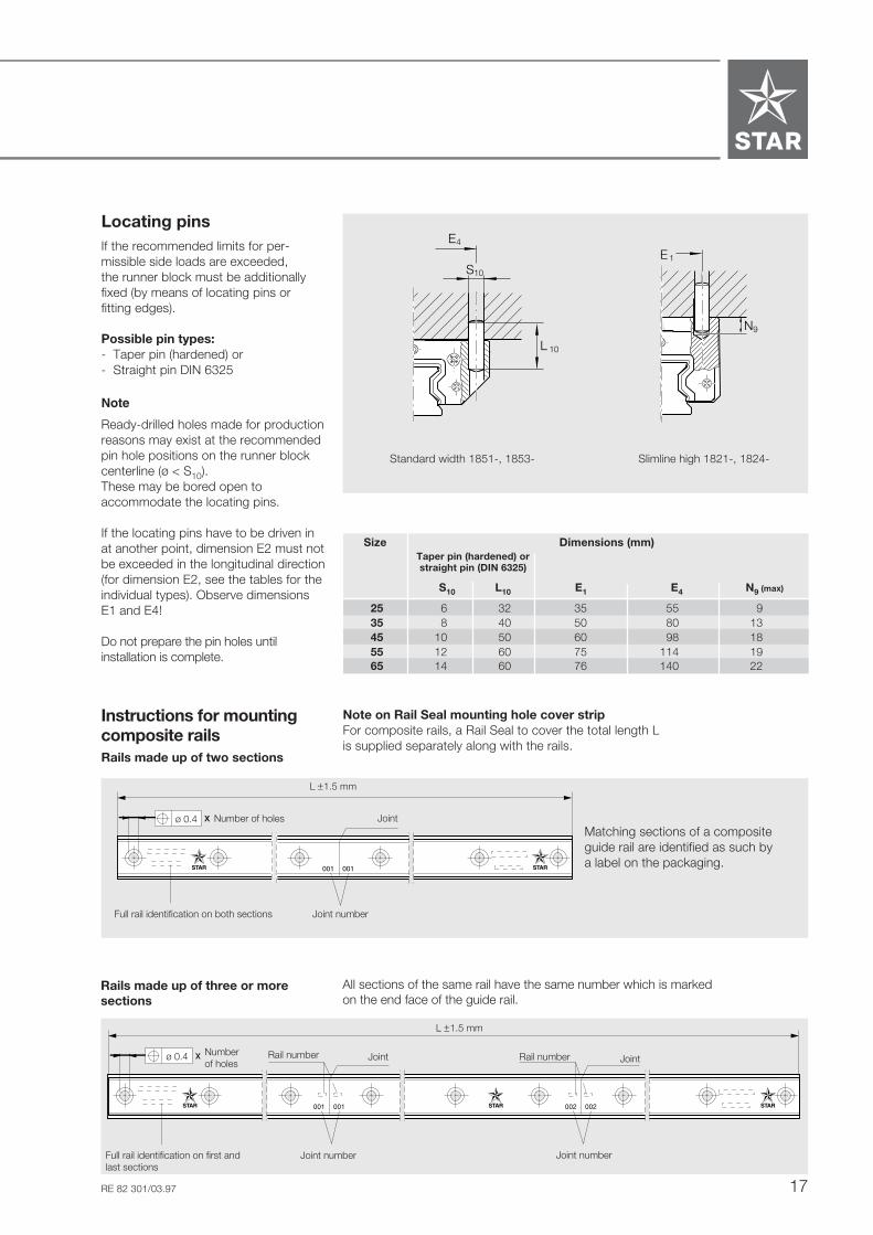
Locating pinsIf the recommended limits for per-missible side loads are exceeded,the runner block must be additionallyfixed (by means of locating pins orfitting edges).
Possible pin types:- Taper pin (hardened) or- Straight pin DIN 6325
Standard width 1851-, 1853- Slimline high 1821-, 1824-
Note
Ready-drilled holes made for productionreasons may exist at the recommendedpin hole positions on the runner blockcenterline (ø < S10).These may be bored open toaccommodate the locating pins.
If the locating pins have to be driven inat another point, dimension E2 must notbe exceeded in the longitudinal direction(for dimension E2, see the tables for theindividual types). Observe dimensionsE1 and E4!
Do not prepare the pin holes untilinstallation is complete.
Size Dimensions (mm)Taper pin (hardened) orstraight pin (DIN 6325)
S10 L10 E1 E4 N9 (max)
25 6 32 35 55 935 8 40 50 80 1345 10 50 60 98 1855 12 60 75 114 1965 14 60 76 140 22
Joint number
Number of holes Joint
Full rail identification on both sections
L ±1.5 mm
Numberof holes
Rail number Joint Rail number Joint
Joint numberJoint numberFull rail identification on first andlast sections
L ±1.5 mm
Rails made up of three or moresections
All sections of the same rail have the same number which is markedon the end face of the guide rail.
ø 0.4
ø 0.4
Instructions for mountingcomposite railsRails made up of two sections
Note on Rail Seal mounting hole cover stripFor composite rails, a Rail Seal to cover the total length Lis supplied separately along with the rails.
10S
L 10
STAR
4E1E
STAR
N9
Matching sections of a compositeguide rail are identified as such bya label on the packaging.
STAR – Roller Rail Systems
18 RE 82 301/03.97
Mounting Instructions for the Rail Seal Mounting Hole Cover Strip
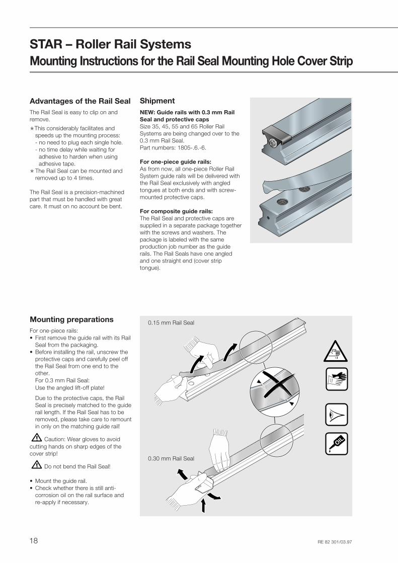
Advantages of the Rail SealThe Rail Seal is easy to clip on andremove.
This considerably facilitates andspeeds up the mounting process:- no need to plug each single hole.- no time delay while waiting for
adhesive to harden when usingadhesive tape.
The Rail Seal can be mounted andremoved up to 4 times.
The Rail Seal is a precision-machinedpart that must be handled with greatcare. It must on no account be bent.
OIL
ShipmentNEW: Guide rails with 0.3 mm RailSeal and protective capsSize 35, 45, 55 and 65 Roller RailSystems are being changed over to the0.3 mm Rail Seal.Part numbers: 1805-.6.-6.
For one-piece guide rails:As from now, all one-piece Roller RailSystem guide rails will be delivered withthe Rail Seal exclusively with angledtongues at both ends and with screw-mounted protective caps.
For composite guide rails:The Rail Seal and protective caps aresupplied in a separate package togetherwith the screws and washers. Thepackage is labeled with the sameproduction job number as the guiderails. The Rail Seals have one angledand one straight end (cover striptongue).
Mounting preparationsFor one-piece rails:• First remove the guide rail with its Rail
Seal from the packaging.• Before installing the rail, unscrew the
protective caps and carefully peel offthe Rail Seal from one end to theother.For 0.3 mm Rail Seal:Use the angled lift-off plate!
Due to the protective caps, the RailSeal is precisely matched to the guiderail length. If the Rail Seal has to beremoved, please take care to remountin only on the matching guide rail!
Caution: Wear gloves to avoidcutting hands on sharp edges of thecover strip!
Do not bend the Rail Seal!
• Mount the guide rail.• Check whether there is still anti-
corrosion oil on the rail surface andre-apply if necessary.
0.15 mm Rail Seal
0.30 mm Rail Seal
19RE 82 301/03.97
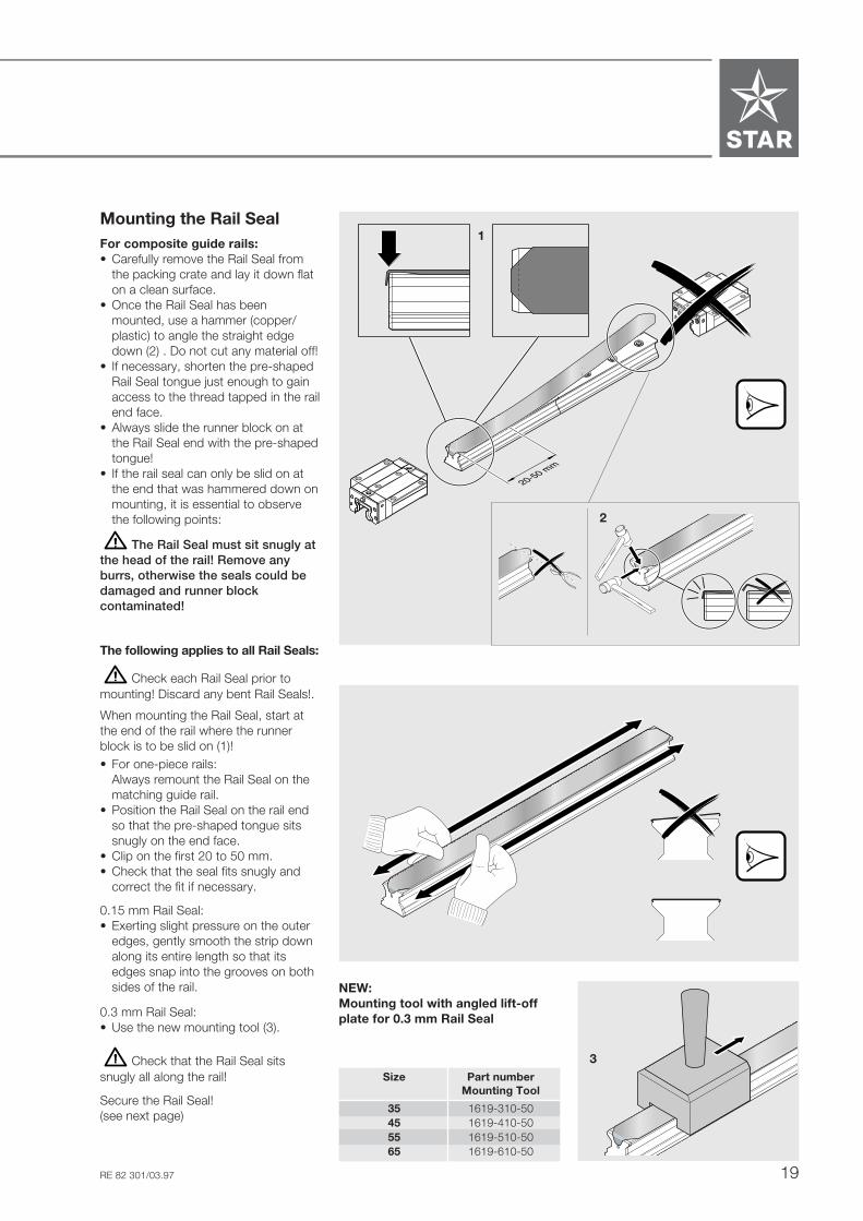
Mounting the Rail SealFor composite guide rails:• Carefully remove the Rail Seal from
the packing crate and lay it down flaton a clean surface.
• Once the Rail Seal has beenmounted, use a hammer (copper/plastic) to angle the straight edgedown (2) . Do not cut any material off!
• If necessary, shorten the pre-shapedRail Seal tongue just enough to gainaccess to the thread tapped in the railend face.
• Always slide the runner block on atthe Rail Seal end with the pre-shapedtongue!
• If the rail seal can only be slid on atthe end that was hammered down onmounting, it is essential to observethe following points:
The Rail Seal must sit snugly atthe head of the rail! Remove anyburrs, otherwise the seals could bedamaged and runner blockcontaminated!
The following applies to all Rail Seals:
Check each Rail Seal prior tomounting! Discard any bent Rail Seals!.
When mounting the Rail Seal, start atthe end of the rail where the runnerblock is to be slid on (1)!• For one-piece rails:
Always remount the Rail Seal on thematching guide rail.
• Position the Rail Seal on the rail endso that the pre-shaped tongue sitssnugly on the end face.
• Clip on the first 20 to 50 mm.• Check that the seal fits snugly and
correct the fit if necessary.
0.15 mm Rail Seal:• Exerting slight pressure on the outer
edges, gently smooth the strip downalong its entire length so that itsedges snap into the grooves on bothsides of the rail.
0.3 mm Rail Seal:• Use the new mounting tool (3).
Check that the Rail Seal sitssnugly all along the rail!
Secure the Rail Seal!(see next page)
STSTARAR
STSTARAR
20-50 mmSTAR
STAR
3Size Part number
Mounting Tool
35 1619-310-5045 1619-410-5055 1619-510-5065 1619-610-50
2
NEW:Mounting tool with angled lift-offplate for 0.3 mm Rail Seal
1
STAR – Roller Rail Systems
20 RE 82 301/03.97
Mounting Instructions for the Rail Seal Mounting Hole Cover Strip
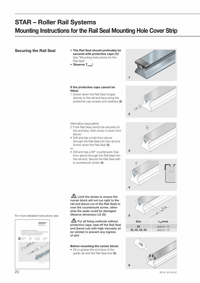
Securing the Rail Seal
1
2
3
4
5
Size LS (mm)
25 approx. 1035, 45, 55, 65 approx. 12
�L S
Deutsche Star
Montagehinweise für das AbdeckbandMounting Instructions for the Rail Seal Mounting Hole Cover StripInstructions de montage pour la bande de protectionIstruzioni di montaggio per il nastro di protezione
bei Kugel- undRollen-Schienen-führungen
pour guidages àbilles et guidagesà rouleaux sur rails
per guide a sferee guide a rullisu rotaia
for Ball andRoller RailSystems
RDEFI 83 641/10.95
ST
ST
AR
AR
For more detailed instructions see:
• The Rail Seal should preferably besecured with protective caps (1)!See "Mounting Instructions for theRail Seal"
• Observe T1min!
If the protective caps cannot befitted:1.Screw down the Rail Seal tongue
directly to the rail end face using theprotective cap screws and washers (2)
Alternative (equivalent):2. If the Rail Seal cannot be secured on
the end face, then screw it down fromabove:
• Drill and tap a hole from abovethrough the Rail Seal into the rail end.Screw down the Rail Seal (3).
or:• Drill and tap a 90° countersunk hole
from above through the Rail Seal intothe rail end. Secure the Rail Seal witha countersunk screw (4).
Limit the stroke to ensure therunner block will not run right to therail end (bevel cut of the Rail Seal) orover the countersunk screw, other-wise the seals could be damaged.Observe dimension LS (5)!
For all fixing methods withoutprotective caps: seal off the Rail Sealend (bevel cut) with high-viscosity oil(or similar) to prevent any ingressof dirt!
6
Before mounting the runner block:• Oil or grease the end face of the
guide rail and the Rail Seal end (6).
OIL

21RE 82 301/03.97
Runner blocks with newblue-colored universal andend seals
The part numbers remain unchangedfor runner blocks with blue seals.
IdentificationRunner blocks with blue seals have anadditional sticker on the packaging.
Universaldichtung
blau
Universal sealblue
Do not use runner blocks withgray seals on guide rails with 0.3 mmRail Seals (1805-.6.-6.)!
Seal color Rail Rail Railwithout with 0.15 with 0.30
Rail Seal Rail Seal Rail Seal
Gray X X
NEW: Blue X X X
X : permissible
: not permissible!
Permissible seal/railcombinations
All runner blocks with blue seals canbe mounted on all guide rails of thesame size- without Rail Seal- with 0.15 mm Rail Seal- with 0.30 mm Rail Seal
STSTARAR
STSTARAR
Blue end seal
Blue universal seal
Technical Update

STAR – Roller Rail Systems
22 RE 82 301/03.97
Load capacities (N) Moments (Nm)
Size C C0 Mt Mt0 ML ML0dyn. stat. dyn. stat.
25 26900 53200 348 690 260 52035 56300 113500 1114 2245 700 140045 92300 184800 2277 4559 1430 286055 128900 248600 3779 7288 2400 4620
Size Accuracy Part numbersclass
Preload Preload Preload0.03 C 0.08 C 0.13 C
25 UP 1851-219-10 1851-229-10 1851-239-10SP 1851-211-10 1851-221-10 1851-231-10P 1851-212-10 1851-222-10 1851-232-10H 1851-213-10 1851-223-10 –
35 UP 1851-319-10 1851-329-10 1851-339-10SP 1851-311-10 1851-321-10 1851-331-10P 1851-312-10 1851-322-10 1851-332-10H 1851-313-10 1851-323-10 –
45 UP 1851-419-10 1851-429-10 1851-439-10SP 1851-411-10 1851-421-10 1851-431-10P 1851-412-10 1851-422-10 1851-432-10H 1851-413-10 1851-423-10 –
55 UP 1851-519-10 1851-529-10 1851-539-10SP 1851-511-10 1851-521-10 1851-531-10P 1851-512-10 1851-522-10 1851-532-10H 1851-513-10 1851-523-10
Runner Blocks
Runner Blocks 1851-Standard width
Special version:Zinc-iron coating, yellow chromated, inaccuracy class H and preload 0.03 C.Part numbers:1851-.13-30
Part numbers
Notes on dynamic load capacitiesand moments
The dynamic load capacities andmoments are based on 100,000 mtravel.For comparison with the 50,000 mtravel sometimes applied for rail-typeguideways, the figures for C, Mt andML in the table should be multipliedby 1.23.
Mt Mt0ML ML0
ML ML0
STSTARAR
CC0
C
C0
C
C0
23RE 82 301/03.97
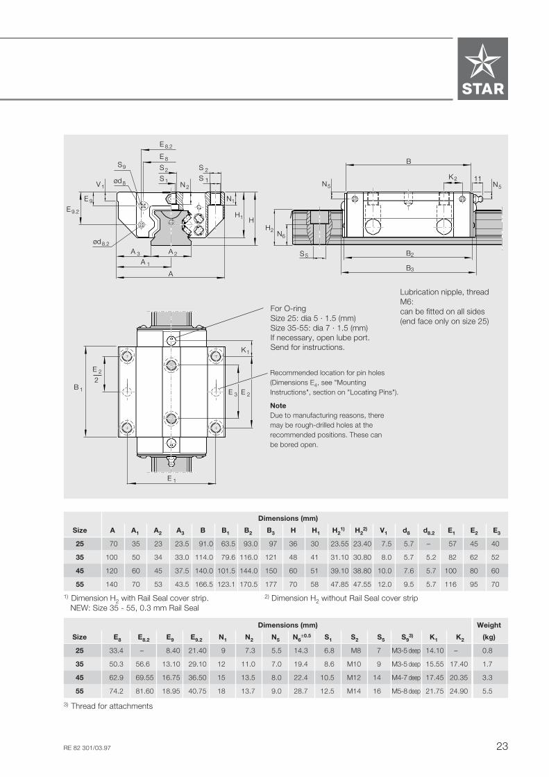
Dimensions (mm)
Size A A1 A2 A3 B B1 B2 B3 H H1 H21) H2
2) V1 d8 d8.2 E1 E2 E3
25 70 35 23 23.5 91.0 63.5 93.0 97 36 30 23.55 23.40 7.5 5.7 – 57 45 40
35 100 50 34 33.0 114.0 79.6 116.0 121 48 41 31.10 30.80 8.0 5.7 5.2 82 62 52
45 120 60 45 37.5 140.0 101.5 144.0 150 60 51 39.10 38.80 10.0 7.6 5.7 100 80 60
55 140 70 53 43.5 166.5 123.1 170.5 177 70 58 47.85 47.55 12.0 9.5 5.7 116 95 70
Recommended location for pin holes(Dimensions E4, see "MountingInstructions", section on "Locating Pins").
NoteDue to manufacturing reasons, theremay be rough-drilled holes at therecommended positions. These canbe bored open.
E 8
S 2
S 1N 2
S 2
S 1
N1E 9
V 1
E 9.2
A 3 2
A 1
A
A
H1 H
E 8.2
K1
E 3 E 2
E 1
E 2
2B 1
ød8
ød8.2
S9
B3
B2
B
K2 11N5 N5
S 5
H2N6
Lubrication nipple, threadM6:can be fitted on all sides(end face only on size 25)
Dimensions (mm) Weight
Size E8 E8.2 E9 E9.2 N1 N2 N5 N6±0.5 S1 S2 S5 S9
3) K1 K2 (kg)
25 33.4 – 8.40 21.40 9 7.3 5.5 14.3 6.8 M8 7 M3-5 deep 14.10 – 0.8
35 50.3 56.6 13.10 29.10 12 11.0 7.0 19.4 8.6 M10 9 M3-5 deep 15.55 17.40 1.7
45 62.9 69.55 16.75 36.50 15 13.5 8.0 22.4 10.5 M12 14 M4-7 deep 17.45 20.35 3.3
55 74.2 81.60 18.95 40.75 18 13.7 9.0 28.7 12.5 M14 16 M5-8 deep 21.75 24.90 5.5
3) Thread for attachments
For O-ringSize 25: dia 5 · 1.5 (mm)Size 35-55: dia 7 · 1.5 (mm)If necessary, open lube port.Send for instructions.
1) Dimension H2 with Rail Seal cover strip. 2) Dimension H2 without Rail Seal cover strip NEW: Size 35 - 55, 0.3 mm Rail Seal

STAR – Roller Rail Systems
24 RE 82 301/03.97
Runner Blocks
Runner Blocks 1853-Standard width long
Special version:Zinc-iron coating, yellow chromated, inaccuracy class H and preload 0.03 C.Part numbers:1853-.13-30
Size Accuracy Part numbersclass
Preload Preload Preload0.03 C 0.08 C 0.13 C
25 UP 1853-219-10 1853-229-10 1853-239-10SP 1853-211-10 1853-221-10 1853-231-10P 1853-212-10 1853-222-10 1853-232-10H 1853-213-10 1853-223-10 –
35 UP 1853-319-10 1853-329-10 1853-339-10SP 1853-311-10 1853-321-10 1853-331-10P 1853-312-10 1853-322-10 1853-332-10H 1853-313-10 1853-323-10 –
45 UP 1853-419-10 1853-429-10 1853-439-10SP 1853-411-10 1853-421-10 1853-431-10P 1853-412-10 1853-422-10 1853-432-10H 1853-413-10 1853-423-10 –
55 UP 1853-519-10 1853-529-10 1853-539-10SP 1853-511-10 1853-521-10 1853-531-10P 1853-512-10 1853-522-10 1853-532-10H 1853-513-10 1853-523-10 –
65 UP 1853-619-10 1853-629-10 1853-639-10SP 1853-611-10 1853-621-10 1853-631-10P 1853-612-10 1853-622-10 1853-632-10H 1853-613-10 1853-623-10 –
Load capacities (N) Moments (Nm)
Size C C0 Mt Mt0 ML ML0dyn. stat. dyn. stat. dyn. stat.
25 33300 70000 432 908 420 90035 69700 149300 1375 2953 1135 243045 119200 256600 2941 6331 2520 543055 165000 345300 4837 10122 4030 844065 265500 525600 9410 18630 7960 15760
ML ML0Mt Mt0
ML ML0
Notes on dynamic load capacitiesand moments
The dynamic load capacities andmoments are based on 100,000 mtravel.For comparison with the 50,000 mtravel sometimes applied for rail-typeguideways, the figures for C, Mt andML in the table should be multipliedby 1.23.
Part numbers
CC0
C
C0
C
C0

25RE 82 301/03.97
K1
E 3 E 2
E 1
E 2
2B 1
E 8
S 2
S 1N 2
S 2
S 1
N1E 9
V1
E 9.2
A 3 2
A 1
A
A
H1 H
E 8.2
ød8
ød8.2
S 5
H2N6
B3
B2
B
K 2 11N5 N5
S9
Dimensions (mm)
Size A A1 A2 A3 B B1 B2 B3 H H1 H21) H2
2) V1 d8 d8.2 E1 E2 E3
25 70 35 23 23.5 109.0 81.5 111.0 115 36 30 23.55 23.40 7.5 5.7 – 57 45 40
35 100 50 34 33.0 138.0 103.6 140.0 145 48 41 31.10 30.80 8.0 5.7 5.2 82 62 52
45 120 60 45 37.5 172.5 134.0 176.5 183 60 51 39.10 38.80 10.0 7.6 5.7 100 80 60
55 140 70 53 43.5 205.5 162.1 209.5 216 70 58 47.85 47.55 12.0 9.5 5.7 116 95 70
65 170 85 63 53.5 254.0 194.0 258.5 264 90 76 58.15 57.85 15.0 – – 142 110 82
Dimensions (mm) Weight
Size E8 E8.2 E9 E9.2 N1 N2 N5 N6±0.5 S1 S2 S5 S9
3) K1 K2 (kg)
25 33.4 – 8.40 21.40 9 7.3 5.5 14.3 6.8 M8 7 M3-5 deep 23.10 – 1.1
35 50.3 56.60 13.10 29.10 12 11.0 7.0 19.4 8.6 M10 9 M3-5 deep 27.55 29.4 2.5
45 62.9 69.55 16.75 36.50 15 13.5 8.0 22.4 10.5 M12 14 M4-7 deep 33.70 36.6 4.7
55 74.2 81.60 18.95 40.75 18 13.7 9.0 28.7 12.5 M14 16 M5-8 deep 41.25 44.4 7.7
65 35.0 106.00 9.30 55.00 23 21.5 9.3 36.5 14.5 M16 18 M4-7 deep 53.80 57.0 14.5
For O-ringSize 25: dia 5 · 1.5 (mm)Size 35-65: dia 7 · 1.5 (mm)If necessary, open lube port.Send for instructions.
Recommended location for pin holes(Dimensions E4, see "Mounting In-Instructions", section on "Locating Pins").
NoteDue to manufacturing reasons, there may berough-drilled holes at the recommended positions.These can be bored open.
E 9
E 9.2
E 8.2
E 8
STAR65
Lubrication nipple, thread M6:can be fitted on all sides(end face only on size 25)
3) Thread for attachments
1) Dimension H2 with Rail Seal cover strip. NEW: Size 35 - 65, 0.3 mm Rail Seal 2) Dimension H2 without Rail Seal cover strip

STAR – Roller Rail Systems
26 RE 82 301/03.97
Size Accuracy Part numbersclass
Preload Preload Preload0.03 C 0.08 C 0.13 C
25 UP 1821-219-10 1821-229-10 1821-239-10SP 1821-211-10 1821-221-10 1821-231-10P 1821-212-10 1821-222-10 1821-232-10H 1821-213-10 1821-223-10 –
35 UP 1821-319-10 1821-329-10 1821-339-10SP 1821-311-10 1821-321-10 1821-331-10P 1821-312-10 1821-322-10 1821-332-10H 1821-313-10 1821-323-10 –
45 UP 1821-419-10 1821-429-10 1821-439-10SP 1821-411-10 1821-421-10 1821-431-10P 1821-412-10 1821-422-10 1821-432-10H 1821-413-10 1821-423-10 –
55 UP 1821-519-10 1821-529-10 1821-539-10SP 1821-511-10 1821-521-10 1821-531-10P 1821-512-10 1821-522-10 1821-532-10H 1821-513-10 1821-523-10 –
Runner Blocks
Runner Blocks 1821-Slimline high
Special version:Zinc-iron coating, yellow chromated, inaccuracy class H and preload 0.03 C.Part numbers:1821-.13-30
Load capacities (N) Moments (Nm)
Size C C0 Mt Mt0 ML ML0dyn. stat. dyn. stat.
25 26900 53200 348 690 260 52035 56300 113500 1114 2245 700 140045 92300 184800 2277 4559 1430 286055 128900 248600 3779 7288 2400 4620
Part numbers
Notes on dynamic load capacitiesand moments
The dynamic load capacities andmoments are based on 100,000 mtravel.For comparison with the 50,000 mtravel sometimes applied for rail-typeguideways, the figures for C, Mt andML in the table should be multipliedby 1.23.
Mt Mt0 ML ML0ML ML0
STSTARAR
STSTARAR
CC0
C
C0
C
C0

27RE 82 301/03.97
Dimensions (mm) Weight
Size E8 E8.2 E9 E9.2 N3 N5 N6±0.5 S2 S5 S9
3) K1 K2 (kg)
25 33.4 – 12.40 25.40 9 9.5 14.3 M6 7 M3-5 deep 19.10 – 0.6
35 50.3 56.60 20.10 36.10 13 14.0 19.4 M8 9 M3-5 deep 21.55 23.40 1.5
45 62.9 69.55 26.75 46.50 18 18.0 22.4 M10 14 M4-7 deep 27.45 30.35 3.1
55 74.2 81.60 28.95 50.75 19 19.0 28.7 M12 16 M5-8 deep 31.75 34.95 4.6
For O-ringSize 25: dia 5 · 1.5 (mm)Size 35-55: dia 7 · 1.5 (mm)If necessary, open lube port.Send for instructions.Lube adapter, see"Accessories".
K1
E 2
E 1
B 1
K2
E 8
ød
ød
8 S 2
N3E 9
V 1
A 3 2
A 1
A
A
S 2
8.2
B3
B2
B
11
N5
S 5
H2 N6
N5
E 9.2 H1 H
E 8.2
S9
Dimensions (mm)
Size A A1 A2 A3 B B1 B2 B3 H H1 H21) H2
2) V1 d8 d8.2 E1 E2
25 48 24 23 12.5 91.0 63.5 93.0 97 40 34 23.55 23.40 7.5 5.7 – 35 35
35 70 35 34 18.0 114.0 79.6 116.0 121 55 48 31.10 30.80 8.0 5.7 5.2 50 50
45 86 43 45 20.5 140.0 101.5 144.0 150 70 61 39.10 38.80 10.0 7.6 5.7 60 60
55 100 50 53 23.5 166.5 123.1 170.5 177 80 68 47.85 47.55 12.0 9.5 5.7 75 75
Lubrication nipple, thread M6:can be fitted on all sides(end face only on size 25)
3) Thread for attachments
1) Dimension H2 with Rail Seal cover strip. 2) Dimension H2 without Rail Seal cover strip. NEW: Size 35 - 55, 0.3 mm Rail Seal

STAR – Roller Rail Systems
28 RE 82 301/03.97
Runner Blocks 1824-Slimline high long(Size 65: slimline long)
Special version:Zinc-iron coating, yellow chromated, inaccuracy class H and preload 0.03 C.Part numbers:1824-.13-30
Runner Blocks
Size Accuracy Part numbersclass
Preload Preload Preload0.03 C 0.08 C 0.13 C
25 UP 1824-219-10 1824-229-10 1824-239-10SP 1824-211-10 1824-221-10 1824-231-10P 1824-212-10 1824-222-10 1824-232-10H 1824-213-10 1824-223-10 –
35 UP 1824-319-10 1824-329-10 1824-339-10SP 1824-311-10 1824-321-10 1824-331-10P 1824-312-10 1824-322-10 1824-332-10H 1824-313-10 1824-323-10 –
45 UP 1824-419-10 1824-429-10 1824-439-10SP 1824-411-10 1824-421-10 1824-431-10P 1824-412-10 1824-422-10 1824-432-10H 1824-413-10 1824-423-10 –
55 UP 1824-519-10 1824-529-10 1824-539-10SP 1824-511-10 1824-521-10 1824-531-10P 1824-512-10 1824-522-10 1824-532-10H 1824-513-10 1824-523-10 –
65 UP 1824-619-10 1824-629-10 1824-639-10SP 1824-611-10 1824-621-10 1824-631-10P 1824-612-10 1824-622-10 1824-632-10H 1824-613-10 1824-623-10 –
Part numbers
Notes on dynamic load capacitiesand moments
The dynamic load capacities andmoments are based on 100,000 mtravel.For comparison with the 50,000 mtravel sometimes applied for rail-typeguideways, the figures for C, Mt andML in the table should be multipliedby 1.23.
Load capacities (N) Moments (Nm)
Size C C0 Mt Mt0 ML ML0dyn. stat. dyn. stat.
25 33300 70000 432 908 420 90035 69700 149300 1375 2953 1135 243045 119200 256600 2941 6331 2520 543055 165000 345300 4837 10122 4030 844065 265500 525600 9410 18630 7960 15760
Mt Mt0 ML ML0ML ML0
STSTARAR
STSTARAR
CC0
C
C0
C
C0

29RE 82 301/03.97
Dimensions (mm)
Size A A1 A2 A3 B B1 B2 B3 H H1 H21) H2
2) V1 d8 d8.2 E1 E2
25 48 24 23 12.5 109.0 81.5 111.0 115 40 34 23.55 23.40 7.5 5.7 – 35 50
35 70 35 34 18.0 138.0 103.6 140.0 145 55 48 31.10 30.80 8.0 5.7 5.2 50 72
45 86 43 45 20.5 172.5 134.0 176.5 183 70 61 39.10 38.80 10.0 7.6 5.7 60 80
55 100 50 53 23.5 205.5 162.1 209.5 216 80 68 47.85 47.55 12.0 9.5 5.7 75 95
65 126 63 63 31.5 254.0 194.0 258.5 264 90 76 58.15 57.85 15.0 – – 76 120
Dimensions (mm) Weight
Size E8 E8.2 E9 E9.2 N3 N5 N6±0.5 S2 S5 S9
3) K1 K2 (kg)
25 33.4 – 12.40 25.40 9 9.5 14.3 M6 7 M3-5 deep 20.60 – 0.9
35 50.3 56.60 20.10 36.10 13 14.0 19.4 M8 9 M3-5 deep 22.55 24.4 2.0
45 62.9 69.55 26.75 46.50 18 18.0 22.4 M10 14 M4-7 deep 33.70 36.6 4.2
55 74.2 81.60 28.95 50.75 19 19.0 28.7 M12 16 M5-8 deep 41.25 44.4 6.2
65 35.0 106.00 9.30 55.00 21 9.3 36.5 M16 18 M4-7 deep 48.80 52.0 12.0
STAR
E9
E9.2
E8.2
E8
STAR
E 1
K1
E 2 B 1
E 8ød
ød
8 S 2
N3E 9
V 1
A 3 2
A 1
A
A
S 2
8.2
E 9.2 H1 H
E 8.2
K2
B3
B2
B
11
N5
S 5
H2N6
S9
N5
For O-ringSize 25: dia 5 · 1.5 (mm)Size 35-65: dia 7 · 1.5 (mm)If necessary, open lube port.Send for instructions.Lube adapter, see"Accessories".
Lubrication nipple, thread M6:can be fitted on all sides(end face only on size 25)
3) Thread for attachments
65
1) Dimension H2 with Rail Seal cover strip. NEW: Size 35 - 65, 0.3 mm Rail Seal 2) Dimension H2 without Rail Seal cover strip
STAR – Roller Rail Systems
30 RE 82 301/03.97
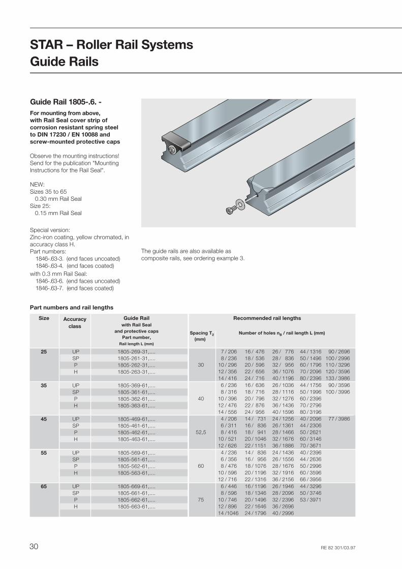
Guide Rails
Guide Rail 1805-.6. -For mounting from above,with Rail Seal cover strip ofcorrosion resistant spring steelto DIN 17230 / EN 10088 andscrew-mounted protective caps
Observe the mounting instructions!Send for the publication "MountingInstructions for the Rail Seal".
NEW:Sizes 35 to 65 0.30 mm Rail SealSize 25: 0.15 mm Rail Seal
The guide rails are also available ascomposite rails, see ordering example 3.
Special version:Zinc-iron coating, yellow chromated, inaccuracy class H.Part numbers:
1846-.63-3. (end faces uncoated)1846-.63-4. (end faces coated)
with 0.3 mm Rail Seal:1846-.63-6. (end faces uncoated)1846-.63-7. (end faces coated)
Size Guide Railwith Rail Seal
and protective capsPart number,
Rail length L (mm)
25 UP 1805-269-31,....SP 1805-261-31,....P 1805-262-31,....H 1805-263-31,....
35 UP 1805-369-61,....SP 1805-361-61,....P 1805-362-61,....H 1805-363-61,....
45 UP 1805-469-61,....SP 1805-461-61,....P 1805-462-61,....H 1805-463-61,....
55 UP 1805-569-61,....SP 1805-561-61,....P 1805-562-61,....H 1805-563-61,....
65 UP 1805-669-61,....SP 1805-661-61,....P 1805-662-61,....H 1805-663-61,....
Part numbers and rail lengths
Recommended rail lengths
Spacing T2 Number of holes nB / rail length L (mm)(mm)
7 / 206 16 / 476 26 / 776 44 / 1316 90 / 26968 / 236 18 / 536 28 / 836 50 / 1496 100 / 2996
30 10 / 296 20 / 596 32 / 956 60 / 1796 110 / 329612 / 356 22 / 656 36 / 1076 70 / 2096 120 / 359614 / 416 24 / 716 40 / 1196 80 / 2396 133 / 39866 / 236 16 / 636 26 / 1036 44 / 1756 90 / 35968 / 316 18 / 716 28 / 1116 50 / 1996 100 / 3996
40 10 / 396 20 / 796 32 / 1276 60 / 239612 / 476 22 / 876 36 / 1436 70 / 279614 / 556 24 / 956 40 / 1596 80 / 3196
4 / 206 14 / 731 24 / 1256 40 / 2096 77 / 39866 / 311 16 / 836 26 / 1361 44 / 2306
52,5 8 / 416 18 / 941 28 / 1466 50 / 262110 / 521 20 / 1046 32 / 1676 60 / 314612 / 626 22 / 1151 36 / 1886 70 / 3671
4 / 236 14 / 836 24 / 1436 40 / 23966 / 356 16 / 956 26 / 1556 44 / 2636
60 8 / 476 18 / 1076 28 / 1676 50 / 299610 / 596 20 / 1196 32 / 1916 60 / 359612 / 716 22 / 1316 36 / 2156 66 / 3956
6 / 446 16 / 1196 26 / 1946 44 / 32968 / 596 18 / 1346 28 / 2096 50 / 3746
75 10 / 746 20 / 1496 32 / 2396 53 / 397112 / 896 22 / 1646 36 / 269614 /1046 24 / 1796 40 / 2996
Accuracyclass

31RE 82 301/03.97
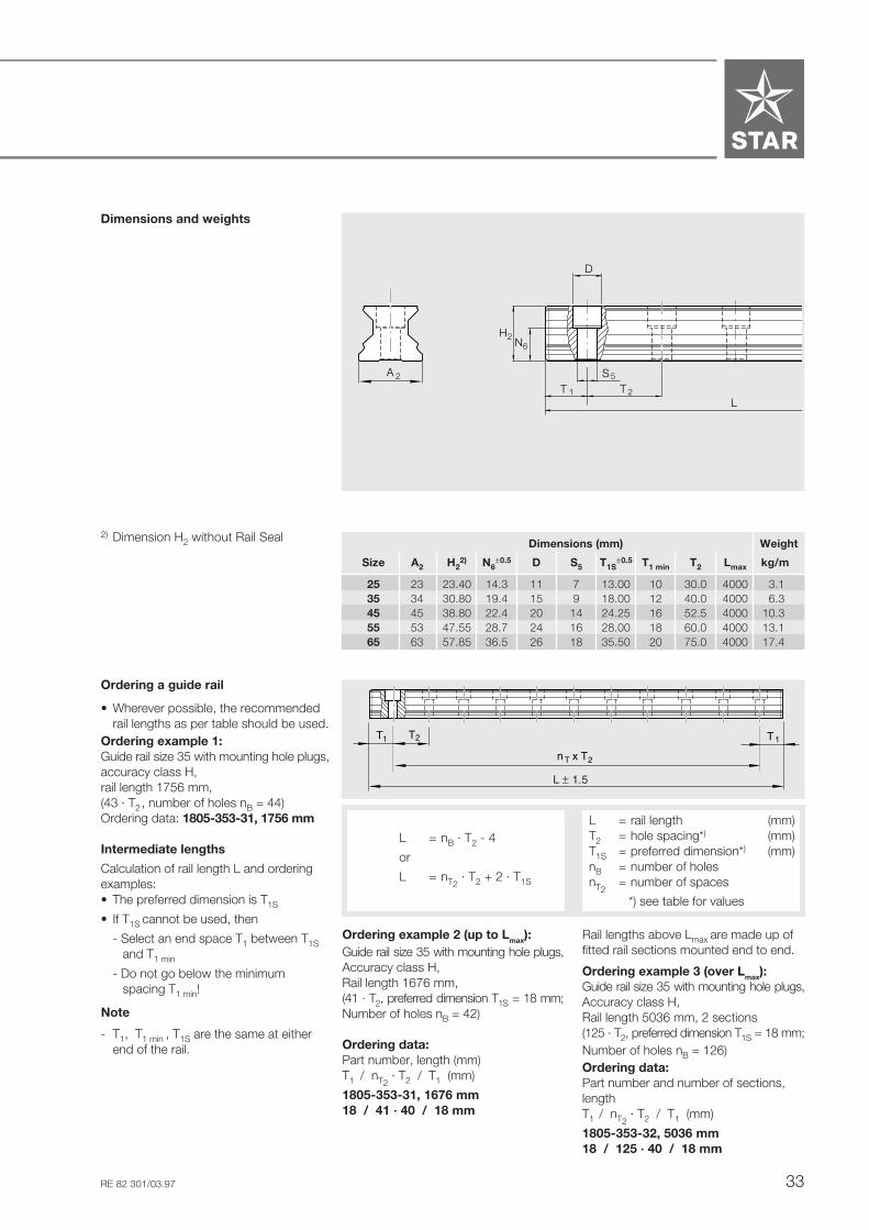
Dimensions and weights
L = nB · T2 - 4
or
L = nT2 · T2 + 2 · T1S
L = rail length (mm)T2 = hole spacing*) (mm)T1S = preferred dimension*) (mm)nB = number of holesnT2
= number of spaces
*) see table for values
Rail lengths above Lmax are made up offitted rail sections mounted end to end.
Ordering example 3 (over Lmax):Guide rail size 35 with Rail Seal,Accuracy class H,Rail length 5036 mm, 2 sections(125 · T2, preferred dimension T1S = 18 mm;Number of holes nB = 126)Ordering data:Part number and number of sections,lengthT1 / nT2
· T2 / T1 (mm)
1805-363-62, 5036 mm18 / 125 · 40 / 18 mm
Ordering example 2 (up to Lmax):Guide rail size 35 with Rail Seal,Accuracy class H,Rail length 1676 mm,(41 · T2, preferred dimension T1S = 18 mm;Number of holes nB = 42)
Ordering data:Part number, length (mm)T1 / nT2
· T2 / T1 (mm)
1805-363-61, 1676 mm18 / 41 · 40 / 18 mm
1) Dimension H2 with Rail Seal.Sizes 35 to 65 with 0.3 mm Rail Seal
2) If end space is less than T1min, therewill be no thread on the rail end faceto secure the Rail Seal !Always secure the Rail Seal!See mounting instructions.Protective cap, screw and washerdelivered along with the rail.
Ordering a guide rail
• Wherever possible, the recommendedrail lengths as per table should be used.
Ordering example 1:Guide rail size 35 with Rail Seal andprotective caps, accuracy class H,rail length 1756 mm,(43 · T2, number of holes nB = 44)Ordering data: 1805-363-61, 1756 mm
Intermediate lengths
Calculation of rail length L and orderingexamples:• The preferred dimension is T1S
• If T1S cannot be used, then
- Select an end space T1 between T1Sand T1 min
- Do not go below the minimumspacing T1 min!
Note
- T1, T1 min , T1S are the same at eitherend of the rail.
T
L
T1 2
2T
T1
n x T
L ± 1.5
2A S 5
H2N6
T 1 T
L
2
D
Dimensions (mm) Weight
Size A2 H21) N6
±0.5 N7 N8 N9 D S5 T1S±0.5 T1 min
2) T2 Lmax kg/m
25 23 23.55 14.3 15.0 15.2 6.5 11.0 7.0 13.00 13 30.0 4000 3.135 34 31.10 19.4 22.0 18.0 7.0 15.0 9.0 18.00 16 40.0 4000 6.345 45 39.10 22.4 30.0 20.0 7.0 20.0 14.0 24.25 18 52.5 4000 10.355 53 47.85 28.7 30.0 20.0 7.0 24.0 16.0 28.00 20 60.0 4000 13.165 63 58.15 36.5 40.0 20.0 7.0 26.0 18.0 35.50 21 75.0 4000 17.4
N7
N9
N8
D
M4

STAR – Roller Rail Systems
32 RE 82 301/03.97
Guide Rail 1805-.5. -For mounting from abovewith plastic mounting hole plugs
Special version:Zinc-iron coating, yellow chromated,in accuracy class H.Part numbers:1846-.13-3. (end faces uncoated)1846-.13-4. (end faces coated)
For special applications:- Guide rails with steel mounting hole
plugs for sizes 25 to 65 in accuracyclasses SP, P, H
Part numbers: 1806-.5.-Steel mounting hole plugs andmounting jig to be ordered separately.Observe the mounting instructions forsteel mounting hole plugs.
Guide Rails
Size Accuracy Guide railclass one-piece composite
Part number Part numberRail length L (mm) No. of sections,
Rail length L (mm)
25 UP 1805-259-31,... 1805-259-3..., ...SP 1805-251-31,... 1805-251-3..., ...P 1805-252-31,... 1805-252-3..., ...H 1805-253-31,... 1805-253-3..., ...
35 UP 1805-359-31,... 1805-359-3..., ...SP 1805-351-31,... 1805-351-3..., ...P 1805-352-31,... 1805-352-3..., ...H 1805-353-31,... 1805-353-3..., ...
45 UP 1805-459-31,... 1805-459-3..., ...SP 1805-451-31,... 1805-451-3..., ...P 1805-452-31,... 1805-452-3..., ...H 1805-453-31,... 1805-453-3..., ...
55 UP 1805-559-31,... 1805-559-3..., ...SP 1805-551-31,... 1805-551-3..., ...P 1805-552-31,... 1805-552-3..., ...H 1805-553-31,... 1805-553-3..., ...
65 UP 1805-659-31,... 1805-659-3..., ...SP 1805-651-31,... 1805-651-3..., ...P 1805-652-31,... 1805-652-3..., ...H 1805-653-31,... 1805-653-3..., ...
Part numbers and rail lengths
Recommended rail lengths
Spacing T2 Number of holes nB / rail length L (mm)(mm)
7 / 206 16 / 476 26 / 776 44 / 1316 90 / 26968 / 236 18 / 536 28 / 836 50 / 1496 100 / 2996
30 10 / 296 20 / 596 32 / 956 60 / 1796 110 / 329612 / 356 22 / 656 36 / 1076 70 / 2096 120 / 359614 / 416 24 / 716 40 / 1196 80 / 2396 133 / 39866 / 236 16 / 636 26 / 1036 44 / 1756 90 / 35968 / 316 18 / 716 28 / 1116 50 / 1996 100 / 3996
40 10 / 396 20 / 796 32 / 1276 60 / 239612 / 476 22 / 876 36 / 1436 70 / 279614 / 556 24 / 956 40 / 1596 80 / 3196
4 / 206 14 / 731 24 / 1256 40 / 2096 77 / 39866 / 311 16 / 836 26 / 1361 44 / 2306
52,5 8 / 416 18 / 941 28 / 1466 50 / 262110 / 521 20 / 1046 32 / 1676 60 / 314612 / 626 22 / 1151 36 / 1886 70 / 3671
4 / 236 14 / 836 24 / 1436 40 / 23966 / 356 16 / 956 26 / 1556 44 / 2636
60 8 / 476 18 / 1076 28 / 1676 50 / 299610 / 596 20 / 1196 32 / 1916 60 / 359612 / 716 22 / 1316 36 / 2156 66 / 3956
6 / 446 16 / 1196 26 / 1946 44 / 32968 / 596 18 / 1346 28 / 2096 50 / 3746
75 10 / 746 20 / 1496 32 / 2396 53 / 397112 / 896 22 / 1646 36 / 269614 /1046 24 / 1796 40 / 2996
33RE 82 301/03.97
Dimensions and weights
L = nB · T2 - 4
or
L = nT2 · T2 + 2 · T1S
L = rail length (mm)T2 = hole spacing*) (mm)T1S = preferred dimension*) (mm)nB = number of holesnT2
= number of spaces
*) see table for values
Rail lengths above Lmax are made up offitted rail sections mounted end to end.
Ordering example 3 (over Lmax):Guide rail size 35 with mounting hole plugs,Accuracy class H,Rail length 5036 mm, 2 sections(125 · T2, preferred dimension T1S = 18 mm;Number of holes nB = 126)Ordering data:Part number and number of sections,lengthT1 / nT2
· T2 / T1 (mm)
1805-353-32, 5036 mm18 / 125 · 40 / 18 mm
Ordering example 2 (up to Lmax):Guide rail size 35 with mounting hole plugs,Accuracy class H,Rail length 1676 mm,(41 · T2, preferred dimension T1S = 18 mm;Number of holes nB = 42)
Ordering data:Part number, length (mm)T1 / nT2
· T2 / T1 (mm)
1805-353-31, 1676 mm18 / 41 · 40 / 18 mm
2) Dimension H2 without Rail Seal
Ordering a guide rail
• Wherever possible, the recommendedrail lengths as per table should be used.
Ordering example 1:Guide rail size 35 with mounting hole plugs,accuracy class H,rail length 1756 mm,(43 · T2, number of holes nB = 44)Ordering data: 1805-353-31, 1756 mm
Intermediate lengths
Calculation of rail length L and orderingexamples:• The preferred dimension is T1S
• If T1S cannot be used, then
- Select an end space T1 between T1Sand T1 min
- Do not go below the minimumspacing T1 min!
Note
- T1, T1 min , T1S are the same at eitherend of the rail.
T
L
T1 2
2T
T1
n x T
L ± 1.5
Dimensions (mm) Weight
Size A2 H22) N6
±0.5 D S5 T1S±0.5 T1 min T2 Lmax kg/m
25 23 23.40 14.3 11 7 13.00 10 30.0 4000 3.135 34 30.80 19.4 15 9 18.00 12 40.0 4000 6.345 45 38.80 22.4 20 14 24.25 16 52.5 4000 10.355 53 47.55 28.7 24 16 28.00 18 60.0 4000 13.165 63 57.85 36.5 26 18 35.50 20 75.0 4000 17.4
2A S 5
H2N6
T 1 TL
2
D

STAR – Roller Rail Systems
34 RE 82 301/03.97
Guide Rails
Guide Rail 1807-
For mounting from below
Special version:Zinc-iron coating, yellow chromated, inaccuracy class H.Part numbers:1848-.13-3. (end faces uncoated)1848-.13-4. (end faces coated)
Size Accuracy Guide railclass one-piece composite
Part number Part numberRail length L (mm) No. of sections,
Rail length L (mm)
25 UP 1807-209-31,... 1807-209-3..., ...SP 1807-201-31,... 1807-201-3..., ...P 1807-202-31,... 1807-202-3..., ...H 1807-203-31,... 1807-203-3..., ...
35 UP 1807-309-31,... 1807-309-3..., ...SP 1807-301-31,... 1807-301-3..., ...P 1807-302-31,... 1807-302-3..., ...H 1807-303-31,... 1807-303-3..., ...
45 UP 1807-409-31,... 1807-409-3..., ...SP 1807-401-31,... 1807-401-3..., ...P 1807-402-31,... 1807-402-3..., ...H 1807-403-31,... 1807-403-3..., ...
55 UP 1807-509-31,... 1807-509-3..., ...SP 1807-501-31,... 1807-501-3..., ...P 1807-502-31,... 1807-502-3..., ...H 1807-503-31,... 1807-503-3..., ...
65 UP 1807-609-31,... 1807-609-3..., ...SP 1807-601-31,... 1807-601-3..., ...P 1807-602-31,... 1807-602-3..., ...H 1807-603-31,... 1807-603-3..., ...
Part numbers and rail lengths
Recommended rail lengths
Spacing T2 Number of holes nB / rail length L (mm)(mm)
7 / 206 16 / 476 26 / 776 44 / 1316 90 / 26968 / 236 18 / 536 28 / 836 50 / 1496 100 / 2996
30 10 / 296 20 / 596 32 / 956 60 / 1796 110 / 329612 / 356 22 / 656 36 / 1076 70 / 2096 120 / 359614 / 416 24 / 716 40 / 1196 80 / 2396 133 / 39866 / 236 16 / 636 26 / 1036 44 / 1756 90 / 35968 / 316 18 / 716 28 / 1116 50 / 1996 100 / 3996
40 10 / 396 20 / 796 32 / 1276 60 / 239612 / 476 22 / 876 36 / 1436 70 / 279614 / 556 24 / 956 40 / 1596 80 / 3196
4 / 206 14 / 731 24 / 1256 40 / 2096 77 / 39866 / 311 16 / 836 26 / 1361 44 / 2306
52,5 8 / 416 18 / 941 28 / 1466 50 / 262110 / 521 20 / 1046 32 / 1676 60 / 314612 / 626 22 / 1151 36 / 1886 70 / 3671
4 / 236 14 / 836 24 / 1436 40 / 23966 / 356 16 / 956 26 / 1556 44 / 2636
60 8 / 476 18 / 1076 28 / 1676 50 / 299610 / 596 20 / 1196 32 / 1916 60 / 359612 / 716 22 / 1316 36 / 2156 66 / 3956
6 / 446 16 / 1196 26 / 1946 44 / 32968 / 596 18 / 1346 28 / 2096 50 / 3746
75 10 / 746 20 / 1496 32 / 2396 53 / 397112 / 896 22 / 1646 36 / 269614 /1046 24 / 1796 40 / 2996

35RE 82 301/03.97
Dimensions and weights
L = nB · T2 - 4
or
L = nT2 · T2 + 2 · T1S
L = rail length (mm)T2 = hole spacing*) (mm)T1S = preferred dimension*) (mm)nB = number of holesnT2
= number of spaces
*) see table for values
Rail lengths above Lmax are made up offitted rail sections mounted end to end.
Ordering example 3 (over Lmax):Guide rail size 35,Accuracy class H,Rail length 5036 mm, 2 sections(125 · T2, preferred dimension T1S = 18 mm;Number of holes nB = 126)Ordering data:Part number and number of sections,length (mm)T1 / nT2
· T2 / T1 (mm)
1807-303-32, 5036 mm18 / 125 · 40 / 18 mm
Ordering example 2 (up to Lmax):Guide rail size 35,Accuracy class H,Rail length 1676 mm,(41 · T2, preferred dimension T1S = 18 mm;Number of holes nB = 42)
Ordering data:Part number, length (mm)T1 / nT2
· T2 / T1 (mm)
1807-303-31, 1676 mm18 / 41 · 40 / 18 mm
Ordering a guide rail
• Wherever possible, the recommendedrail lengths as per table should be used.
Ordering example 1:Guide rail size 35, accuracy class H,rail length 1756 mm,(43 · T2, number of holes nB = 44)Ordering data: 1807-303-31, 1756 mm
Intermediate lengths
Calculation of rail length L and orderingexamples:• The preferred dimension is T1S
• If T1S cannot be used, then
- Select an end space T1 betweenT1S and T1 min
- Do not go below the minimumspacing T1 min!
Note
- T1, T1 min , T1S are the same at eitherend of the rail.
T
L
T1 2
2T
T1
n x T
L ± 1.5
2A S7
H2N7
T 1 T
L
2
Dimensions (mm) Weight
Size A2 H2 N7±0.5 S7 T1S
±0.5 T1 min T2 Lmax kg/m
25 23 23.40 12 M6 13.00 10 30.0 4000 3.135 34 30.80 15 M8 18.00 12 40.0 4000 6.345 45 38.80 19 M12 24.25 16 52.5 4000 10.355 53 47.55 22 M14 28.00 18 60.0 4000 13.165 63 57.85 25 M16 35.50 20 75.0 4000 17.4
STAR – Roller Rail Systems
36 RE 82 301/03.97
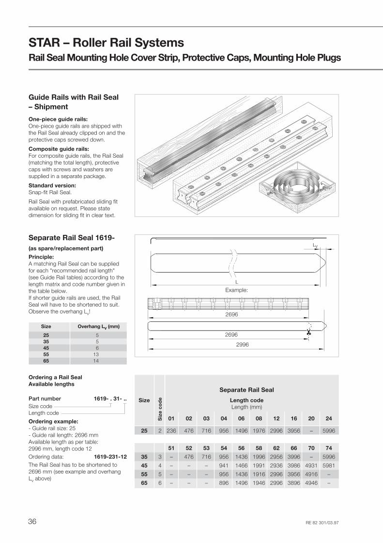
Ordering a Rail SealAvailable lengths
Part number 1619- . 31- ..Size codeLength code
Ordering example:- Guide rail size: 25- Guide rail length: 2696 mmAvailable length as per table:2996 mm, length code 12Ordering data: 1619-231-12The Rail Seal has to be shortened to2696 mm (see example and overhangLv above)
L
LV
2696
2696
2996
Guide Rails with Rail Seal– Shipment
One-piece guide rails:One-piece guide rails are shipped withthe Rail Seal already clipped on and theprotective caps screwed down.
Composite guide rails:For composite guide rails, the Rail Seal(matching the total length), protectivecaps with screws and washers aresupplied in a separate package.
Standard version:Snap-fit Rail Seal.
Rail Seal with prefabricated sliding fitavailable on request. Please statedimension for sliding fit in clear text.
Separate Rail Seal 1619-(as spare/replacement part)
Principle:A matching Rail Seal can be suppliedfor each "recommended rail length"(see Guide Rail tables) according to thelength matrix and code number given inthe table below.If shorter guide rails are used, the RailSeal will have to be shortened to suit.Observe the overhang Lv!
Rail Seal Mounting Hole Cover Strip, Protective Caps, Mounting Hole Plugs
Separate Rail Seal
Size Length codeLength (mm)
01 02 03 04 06 08 12 16 20 24
25 2 236 476 716 956 1496 1976 2996 3956 – 5996
51 52 53 54 56 58 62 66 70 74
35 3 – 476 716 956 1436 1996 2956 3996 – 5996
45 4 – – – 941 1466 1991 2936 3986 4931 5981
55 5 – – – 956 1436 1916 2996 3956 4916 –
65 6 – – – 896 1496 1946 2996 3896 4946 –
Siz
e co
de
Example:
Size Overhang LV (mm)
25 535 545 655 1365 14

37RE 82 301/03.97
Mounting Hole Plugs
Protective capsSize Part numbers
25 1619-239-00 1619-239-20
35 1619-339-10 1619-339-30
45 1619-439-00 1619-439-20
55 1619-539-00 1619-539-20
65 1619-639-00 1619-639-20
Part numbers for protective caps
Size code
Protective CapsSTAR recommends the use ofprotective caps.Protective caps can:- prevent injuries- prevent involuntary lifting of the seal
strip and related ingress of dirt- fix the Rail Seal in place
Part numbers for Mounting Hole PlugsSize Plastic Steel
25 1605-200-90 1606-200-7535 1605-300-90 1606-300-7545 1605-400-90 1606-400-7555 1605-500-90 1606-500-7565 1605-600-90 1606-600-75
A mounting jig with instruction leaflet isavailable for mounting steel mountinghole plugs.
Part numbersSize Mounting jig
25 1619-210-2035 1619-310-2045 1619-410-2055 1619-510-2065 1619-610-20

STAR – Roller Rail Systems
38 RE 82 301/03.97
Accessories
Scraper plate- Material: corrosion-resistant spring
steel to DIN 17230 / EN 10088- Finish: bright
Note for mounting:The mounting screws are supplied withthe scraper plate.When mounting, ensure that there is auniform gap between runner block andscraper plate.
Part numbers, dimensions and weights
Size 65
H
45°
8.1E
9.1E
9E
A
8E
2S
3S
3S
Size Part Dimensions (mm) Weightnumbers A A1 H E8 E8.1 E9 E9.1 øS2 øS3 øS4 D (g)
25 1820-210-00 44.0 1.2 28.5 33.4 40.2 7.9 20.7 7 4 3 1 7.735 1820-310-40 63.0 2.0 39.8 50.3 56.6 12.4 28.4 7 4 3 1 14.345 1820-410-40 77.0 2.0 49.8 62.9 69.6 16.0 35.8 7 5 4 2 44.055 1820-510-40 90.5 2.0 56.2 74.2 81.6 18.2 40.0 7 6 4 2 57.465 1820-610-40 119.0 3.0 74.5 35.0 106.0 8.3 54.0 7 5 5 2 106.0
H
45°
8.1E
9.1E9E
1A
A
D8E
2S
4S
3S
Size 25:For guide rails without Rail Seal andwith 0.15 mm Rail Seal
NEW! Sizes 35 - 65:For 0.30 mm Rail SealPart numbers 1820-.10-40
Old scraper plates types1820-310-00 to 1820-610-00 are notpermissible for 0.3 mm Rail Seals!

39RE 82 301/03.97
End Seal- Material: corrosion-resistant spring
steel to DIN 17230 / EN 10088with plastic seal
- Finish: bright
Note for mounting:The end seal is supplied completewith mounting screws.
STSTARAR
STSTARAR
H
45°
8.1E
9.1E9E
A
D
D
8E
1A
2
1
S
4S
3S
Part numbers and dimensions Size Part Dimensions (mm)numbers A A1 H E8 E8.1 E9 E9.1 øS2 øS3 øS4 D D1
25 1810-210-00 44.0 1.2 28.5 33.4 40.2 7.9 20.7 7 4 3 1 2.635 1810-310-00 63.0 2.0 39.8 50.3 56.6 12.4 28.4 7 4 3 1 2.645 1810-410-00 77.0 2.0 49.8 62.9 69.6 16.0 35.8 7 5 4 2 4.055 1810-510-00 90.5 2.0 56.2 74.2 81.6 18.2 40.0 7 6 4 2 4.865 1810-610-00 119.0 3.0 74.5 35.0 106.0 8.3 54.0 7 5 5 2 5.0
Size 65
H
45°
8.1E
9.1E
9E
A
8E
2S
3S
3S
Size 25:Old seal can still be used with 0.15 mmRail Seal.
NEW! Sizes 35 - 65:With blue seal,for 0.30 mm Rail Seal (and also forguide rails without Rail Seal and with0.15 mm Rail Seal)
Part numbers remain unchanged.

STAR – Roller Rail Systems
40 RE 82 301/03.97
Lubrication plate
- Material: aluminum
Note for mounting:The parts required for variableattachment to the runner block aresupplied along with the lube plate.
The runner block lube nipple canbe used.
For mounting, see "MountingInstructions, Bellows".
Part numbers, dimensions and weights Size Part Dimensions (mm) Weightnumbers A4 B3 H H3 N8 N9 S8 S9 (g)
25 1820-211-20 47 12 36 28.3 14 6 M6 M3 30
STSTARAR
STSTARAR
N8
S8
H3
H
B3N9
4A
Accessories
41RE 82 301/03.97
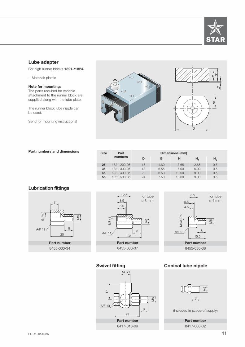
Lube adapterFor high runner blocks 1821-/1824-
- Material: plastic
Note for mounting:The parts required for variableattachment to the runner block aresupplied along with the lube plate.
The runner block lube nipple canbe used.
Send for mounting instructions!
STSTARAR
STSTARAR
Size Part Dimensions (mm)numbers D B H H1 H2
25 1821-200-05 15 4.60 3.65 2.65 0.535 1821-300-05 18 6.55 7.00 6.00 0.545 1821-400-05 22 6.50 10.00 9.00 0.555 1821-500-05 24 7.50 10.00 9.00 0.5
H H
B
D
1
H2
Part numbers and dimensions
Lubrication fittings
Swivel fitting
������������������
A/F 11
M6
22
8
M8
x1
6.5
8.5
12.5
A/F 12
M6
20
8
����������
G 1
/ 8"
7
��������
A/F 9
M6
15.5
8
M6
x0.7
5
4.5
5.5
8.5
Part number
8455-030-34
Part number
8455-030-37
Part number
8455-030-38
Part number
8417-018-09
A/F 10
M6
22
8
17
M8x1
Conical lube nipple
Part number
8417-008-02
M6
8
(included in scope of supply)
for tubeø 6 mm
for tubeø 4 mm
STAR – Roller Rail Systems
42 RE 82 301/03.97
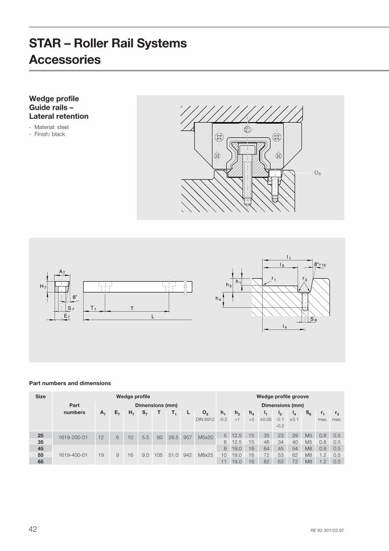
Accessories
Size Wedge profile Wedge profile groove
Part Dimensions (mm) Dimensions (mm)numbers A7 E7 H7 S7 T T1 L O5 h1 h3 h4 l1 l3 l4 S8 r1 r3
DIN 6912 -0.2 +1 +2 ±0.05 -0.1 ±0.1 max. max.-0.2
25 1619-200-01 12 6 10 5.5 60 28.5 957 M5x20 5 12.5 15 35 23 29 M5 0.8 0.535 6 12.5 15 46 34 40 M5 0.8 0.545 8 19.0 16 64 45 54 M8 0.8 0.555 1619-400-01 19 9 16 9.0 105 51.0 942 M8x25 10 19.0 16 72 53 62 M8 1.2 0.565 11 19.0 16 82 63 72 M8 1.2 0.5
8°
8°
H 7
S 7
A7
E7
+
r3r1
15´
TT1
L
h 1h 3
h 4
S 8
l 4
l 3
l 1
Part numbers and dimensions
Wedge profileGuide rails –Lateral retention- Material: steel- Finish: black �������
������
����������
O5

43RE 82 301/03.97
STSTAR
STARAR
STAR
STSTARAR
Protective bellows
- Material: bellows-type protectivecover of polyurethane-coatedpolyester fabric
- For size 25:aluminum lubrication plates
The runner block lube nipple canbe used.
Heat resistant bellows- Material: Nomex fabric, metallized on
both sides.- Non combustible, non flammable- Resistant to sparks, welding splashes
and hot chips- Temperature resistance.Peak temperatures of up to 200°C nearthe protective metal coat possible.Operating temperature for the entirebellows: 100°CAvailable in sizes 25, 35, 45, 55.
The runner block lube nipple canbe used.
Part numbers, protective bellows
Ordering example, protective bellowsSize 35, Type 2,Number of folds: 361820-302-00, 36 folds
Part numbers, heat resistant bellows
Ordering example, heat resistantbellowsSize 35, Type 2,Number of folds: 361820-352-00, 36 folds
Part numbers, protective bellows
Size 25
Size Type 1 Type 2 Type 3
with lubrication plate number with mounting frame number with 2 number
and end plate of and end plate of lubrication plates offolds folds folds
25 1820-201-00 ... 1820-202-00 ... 1820-203-00 ...35 – ... 1820-302-00 ... – ...45 – ... 1820-402-00 ... – ...55 – ... 1820-502-00 ... – ...65 – ... 1820-602-00 ... – ..
25 1820-251-00 ... 1820-252-00 ... 1820-253-00 ...35 – ... 1820-352-00 ... – ...45 – ... 1820-452-00 ... – ...55 – ... 1820-552-00 ... – ...
Size Type 4 Type 5 Type 9
with 2 number with lubrication plate number bellows number
mounting frames of and mounting frame of supplied separately offolds folds (spare part) folds
25 1820-204-00 ... 1820-205-00 ... 1600-209-00 ...35 1820-304-00 ... – ... 1600-309-00 ...45 1820-404-00 ... – ... 1600-409-00 ...55 1820-504-00 ... – ... 1600-509-00 ...65 1820-604-00 ... – ... 1600-609-00 ...
25 1820-254-00 ... 1820-255-00 ... 1600-259-00 ...35 1820-354-00 ... – ... 1600-359-00 ...45 1820-454-00 ... – ... 1600-459-00 ...55 1820-554-00 ... – ... 1600-559-00 ...
Part numbers, heat resistant bellows

STAR – Roller Rail Systems
44 RE 82 301/03.97
Mounting instructions for bellows
The bellows are delivered pre-assembled, complete with mountingscrews.
In types 1 and 2, a threaded hole size M4,10 mm deep and countersunk 2 x 45°,must be drilled in each end face of the rail.
Size 25 - 65:The runner block lube nipple canbe used.
See "Mounting Instructions, Bellows"for mounting.
Dimensions (mm) Factor
Size A4 H H3 H4 N7 S7 S9 W U
25 45 36 28.5 35.0 15 M4 – 12.9 1.3235 64 48 39.0 47.0 22 M4 M6 19.9 1.1845 83 60 49.0 59.0 30 M4 M6 26.9 1.1355 96 70 56.0 69.0 30 M4 M6 29.9 1.1265 120 90 75.0 89.0 40 M4 M8x1 40.4 1.08
Heat resistant bellows
L = rail length (mm)
Dimensions (mm) Factor
Size A4 H H3 H4 N7 S7 S9 W U
25 56 36 35.0 40.5 15 M4 – 19.9 1.3435 74 48 46.0 54.0 22 M4 M6 29.9 1.2145 88 60 54.0 64.0 30 M4 M6 32.9 1.1855 102 70 62.0 75.0 30 M4 M6 37.9 1.16
Rail length calculation
Dimensions, bellows
Dimensions, heat resistant bellows
Bellows calculation
L = Lmin + Lmax + LA
L
L max.L min. L A
L max.L A
A 4
H 3
N7
H4H
212
12
L max.L min.
S 7
S 9
14
12
W3H
4H
Hook and loop fastener
Size 25
Size 25
M4 x 10 deep
M6 x 5 deep
Accessories
Lmax = (Stroke + 30) · U
Lmin = Lmax - Stroke
Number of folds = + 2Lmax
W
L max = bellows extendedL min = bellows compressed
Stroke = stroke (mm)U = calculation factorW = maximum extension (mm)
45RE 82 301/03.97
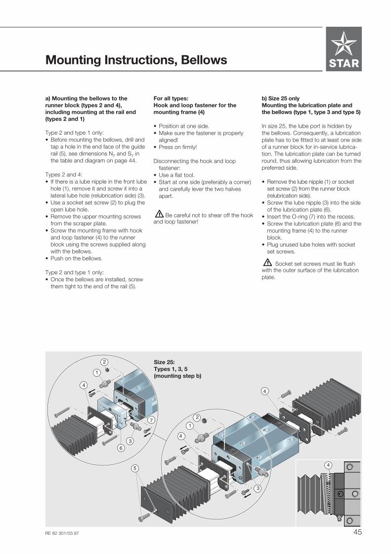
Mounting Instructions, Bellows
For all types:Hook and loop fastener for themounting frame (4)
• Position at one side.• Make sure the fastener is properly
aligned!• Press on firmly!
Disconnecting the hook and loopfastener:
• Use a flat tool.• Start at one side (preferably a corner)
and carefully lever the two halvesapart.
Be careful not to shear off the hookand loop fastener!
b) Size 25 onlyMounting the lubrication plate andthe bellows (type 1, type 3 and type 5)
In size 25, the lube port is hidden bythe bellows. Consequently, a lubricationplate has to be fitted to at least one sideof a runner block for in-service lubrica-tion. The lubrication plate can be turnedround, thus allowing lubrication from thepreferred side.
• Remove the lube nipple (1) or socketset screw (2) from the runner block(relubrication side).
• Screw the lube nipple (3) into the sideof the lubrication plate (6).
• Insert the O-ring (7) into the recess.• Screw the lubrication plate (6) and the
mounting frame (4) to the runnerblock.
• Plug unused lube holes with socketset screws.
Socket set screws must lie flushwith the outer surface of the lubricationplate.
STSTARAR
STSTARAR
STARAR
STAR
1
2
3
4
5
4
4
2
7
Size 25:Types 1, 3, 5(mounting step b)
1
63
4
a) Mounting the bellows to therunner block (types 2 and 4),including mounting at the rail end(types 2 and 1)
Type 2 and type 1 only:• Before mounting the bellows, drill and
tap a hole in the end face of the guiderail (5), see dimensions N7 and S7 inthe table and diagram on page 44.
Types 2 and 4:• If there is a lube nipple in the front lube
hole (1), remove it and screw it into alateral lube hole (relubrication side) (3).
• Use a socket set screw (2) to plug theopen lube hole.
• Remove the upper mounting screwsfrom the scraper plate.
• Screw the mounting frame with hookand loop fastener (4) to the runnerblock using the screws supplied alongwith the bellows.
• Push on the bellows.
Type 2 and type 1 only:• Once the bellows are installed, screw
them tight to the end of the rail (5).

STAR – Roller Rail Systems
46 RE 82 301/03.97
Maintenance and Lubrication
LubricationSTAR Roller Rail Systems are deliveredfilled with an anti-corrosion agent. Eitheroil or grease can be used as a lubricant.
Before start-up, make sure the systemhas sufficient initial lubrication.
Short strokeStroke < 2 runner block lengths:- Provide 2 lube ports per runner blockand lubricate these!
Stroke < 0.5 runner block length:- Provide 2 lube ports per runner block
and lubricate these!- Move the runner block 2 x runner
block length per lubricating cycle.If this is not possible, pleaseconsult STAR.
Lubricant quantities as per Table 1.Apply the specified lubricant quantityper lube port.
Grease lubricants Grease quantity as specified in table.
Recommendation:Anti-friction bearing greases KP2K toDIN 51825:Consistency class NLGI 2 to DIN 51818
Do not use greases containingsolid particle lubricants(e.g., graphite or MoS2)!
Initial lubrication in two steps:First add half the grease, then move therunner block back and forth so that thegrease is evenly distributed beforeadding the remaining grease!
Oil quantity as specified in table.Oil lubricants Add the entire oil quantityin one go!
Lubricant quantities
Size Grease lubricants Oil lubricantsInitial lubrication In-service lubrication Initial and in-service lubrication
(cm3) (cm3) (cm3)
25 1.2 0.6 1.235 1.3 0.7 1.345 1.5 0.8 1.555 2.0 1.0 2.065 4.0 2.0 4.0
Table 1
Maintenance Dirt can settle and encrust on guiderails, especially when these are notenclosed. To insure that seals and RailSeal cover strips will retain theirfunctionality, this dirt must be removedat regular intervals.
It is advisable to run the machinethrough a full "cleaning cycle" over theentire installed rail length at least twice aday, but no later than the end of every8-hour shift. Always run a cleaning cyclebefore shutting down the machine.
The quantities listed in the tableare valid for:F ≤ 0.3 Cv ≤ 1 m/sLubrication interval ≤ 40,000 m
If the equipment is to operate in anenvironment subject to dirt or vibrationand shock loads, etc., we recommendshortening the in-service lubricationinterval.

47RE 82 301/03.97
Stroke > 2 runner block lengths:- Provide 1 lube port per runner block.Oil lubricant to ISO VG 220.Lubricant quantities to Table 2.
Lubricant quantities for one-point oil lubrication
Size Oil lubricant quantity / pulse Pulses(cm3) per lube cycle
25 0.6 235 0.6 245 0.6 355 0.6 365 0.6 6
Installation at an angleabout the centerline
Stroke > 2 runner block lengths:- Provide 1 lube port per runner block.Add the lubricant quantity as specifiedin Table 1 in one pulse.
Stroke < 2 runner block lengths:- Provide 2 lube ports per runner block.Add the lubricant quantity as specifiedin Table 1 in one pulse.If this is not possible, please consultSTAR.
1 lube port
1 lube port
0 - max. 90º
0 - max. 90º
Table 2
2 lube ports
2 lube ports
0 - max. 90º
Stroke < 2 runner block lengths:- Provide 2 lube ports per runner block.Oil lubricant to ISO VG 220.Lubricant quantities to Table 2.Apply the specified lubricant quantityper lube port.
One-point oil lubricationNotesRecommended interval between twopulses: 10 seconds.Example for size 45:3 pulses of 0.6 cm3 each in 20 seconds.
The quantities listed in the tableare valid for:F ≤ 0.3 Cv ≤ 1 m/sLubrication interval ≤ 40,000 m
If the equipment is to operate in anenvironment subject to dirt or vibrationand shock loads, etc., we recommendshortening the in-service lubricationinterval.

STAR – Roller Rail Systems
48 RE 82 301/03.97
Deutsche Star GmbHD-97419 Schweinfurt
Telephone +49-97 21-9 37-0
Telefax +49-97 21-9 37-275(general)
Telefax +49-97 21-9 37-250(direct)
Roller Rail SystemsRE 82 301/03.97
Prin
ted
on c
hlor
ine
free
pape
rGreat care has been taken during the compilationof this publication to ensure all the information con-tained is accurate. We accept no responsibilityhowever for any damage resulting from incorrector incomplete information contained.
For deliveries and other services in the course ofcommercial business, the general terms and con-ditions for supplies and services contained in thevalid price lists and the confirmations of order apply.
As our products are constantly in the process offurther development, they are subject to alterationwithout notice.
STAR, Ball Rail and are trademarks registeredfor Deutsche Star GmbH, Germany.
Roller Rail is a trademark ofDeutsche Star GmbH, Germany.
This publication or any part thereof may not bereproduced without our written permission.
Printed in Germany - p 97/10/5/SK