roof bolting guidelines in south african collieries 020205 booklet.pdf · 2017-05-29 · roof...
TRANSCRIPT

Safety in Mines Research Advisory Committee
Roof Bolting Guidelines in
South African Collieries
I. Canbulat, A. Wilkinson and G. Prohaska Groundwork Consulting (Pty) Ltd
Research Agency : Groundwork Consulting (Pty) Ltd Project No : SIM 020205 Date : March 2006
2
Introduction This guide was produced in response to a need identified in the South African coal mining industry to determine the best roof bolting systems for different geotechnical environments. Van der Merwe et al. (SIMRAC project COL 613, 2001) noted that the majority of falls of ground continue to occur under supported roof. For this reason SIMRAC initiated a research project for the purpose of obtaining an understanding of the fundamental mechanisms of roof support systems and developing guidelines and design methodologies for their improvement. To this end, all currently available roof bolt support elements and related machinery were evaluated underground in different rock types, namely sandstone, shale, and coal. The five important components of a bolting system are: resin, bolt, hole, machinery/equipment, rock type. As the main objective of this book, important parameters and design implications of these five components are documented. A detailed literature review was also conducted. This showed that roof bolting is by far the most common support system used in South African collieries. Roof bolts are available in many forms, and the methods for attaching them to the rock mass are as varied. Full-column single-resin bolts, full-column slow-fast combination resin bolts, resin point anchors and mechanical anchors are the most widely used roofbolting systems in South Africa. The review also showed that since the introduction of mechanical bolts in the 1940s, a significant amount of research has been carried out on understanding the behaviour of roof bolts. Despite the fact that roof bolting has been the most researched aspect of coal mining, falls of ground remain the single largest cause (accounting for about 25 %) of fatalities in South African coal mines. There is no commonly accepted design approach for underground coal mines. Roof bolts have been found to behave differently under different loading conditions, despite being tested in fully controlled laboratory environments. The most important key to the design of roof support systems is a better understanding of roof behaviour in different geotechnical environments through continuous in situ monitoring.

3
1 Review of roof bolting literature Over 200 publications were included in this review and details can be found in the final report of SIM 020205, entitled “An investigation into the support systems in South African collieries”. The literature review showed that in the early years, the design of roof bolt patterns was based on local experience and the judgement of mining personnel. The suspension mechanism was the most easily understood and most widely used roof bolting mechanism. However, significant advances have been made over the last 20 years, in particular, the development of resin anchors, tendon elements, and installation hardware. These advances have resulted in an increase in the use of full column resin bolts. The design of roof bolt patterns has also been improved, and four main rock reinforcement techniques have been developed: simple skin control, beam building, suspension, and keying. The geology and the stress levels determine the appropriate mechanism for a particular application. Investigations into the causes of roof falls in South African collieries have highlighted that, whilst roof conditions are comparatively better in South Africa, the roof bolt densities are relatively low in comparison with those used in the USA, the UK and Australia. Consequently, the main cause of FOGs was found to be excessive bolt spacing, permitting skin failures between the bolts. The importance of tensioning roof bolts remains a subject of controversy. As will be seen in the following chapters, the critical roof deformations in South African collieries are relatively small. Therefore, tensioned roof bolts are beneficial in that they allow less roof deformation to take place after the support has been installed. However, if the bolting system is stiff enough, tensioning may not be required. Numerical models are useful in understanding roof and roof bolt behaviour; however, extensive laboratory studies are required for determining the input parameters. The Australian technique, subsequently adapted in the UK, has proven that numerical modelling can be used to back-analyse underground scenarios. Once the model is calibrated, the results obtained from the numerical models can be used for design. The selection of roof bolt type for different geological environments is well documented. However, the changing conditions underground must also be determined and the design and the support system have to be modified accordingly. Widespread instrumentation and vigilant visual observations are important for ensuring safety and stability in coal mines.

4
While the effect of roof bolt diameter on support performance is well understood, there is still controversy over the required length of the bolts. It has been shown by Molinda et al. (2000) that the probability of roof failures in the U.S.A. increases with decreasing bolt length. Since skin failures (< 0.5 m thick) are more common in South Africa than larger roof falls (Canbulat and Jack, 1998, van der Merwe and Madden, 2002), short roof bolts for skin control may nevertheless make up part of an effective support system. In conclusion, despite the fact that roof bolting has been the most researched aspect of coal mining, FOGs still remain the single largest cause of fatalities in South African coal mines, and there are no commonly accepted design approaches. Roof bolts were found to behave differently under different loading conditions, emphasising the importance of understanding the interaction between the roof bolts and the rockmass. The most important key to the design of a roof support system is a better understanding of roof behaviour in different geotechnical environments through continuous in situ monitoring. The purpose of this guide, then, is to summarize detailed in situ and laboratory findings with regard to roofbolt system performance in South African conditions; and to attempt to integrate these into an improved roofbolting design methodology with associated quality control and monitoring procedures.
2 Short encapsulation pull testing 2.1 Introduction This section provides guidance on a reliable and accurate testing procedure for determining the mechanical properties of roof bolts. It is aimed at rock engineers and technicians who are familiar with roof bolt support operations and are involved in this evaluation. The results from the suggested testing procedure can be used for roof bolt design verification and routine quality monitoring. The ability of fully bonded roof bolt systems to provide reinforcement depends on the strength and stiffness of the bond between the roof bolt and the rock. These qualities can be measured in the laboratory or underground, with the use of short encapsulation pull testing (SEPT). Each of the elements of a roofbolting system - hole size, drill bit size and type, resin properties, steel properties and bolt profile – should be developed to maximise the bond strength, and yet provide a system capable of rapid installation. The torque nut and plate assembly should be designed to give

5
resin-mixing quality control during installation and to allow post-installation quality auditing to be carried out.
2.2 Bond strength Bond strength is measured through short encapsulation pull testing (SEPT). The objective of the test is to fail the resin bond and to characterise the bond failure in terms of bond strength and system stiffness. Thus, in order to measure the bond strength, it is necessary to shear the bond on the bolt-resin or resin-rock interface. With the high-strength, high-stiffness, polyester resins that are in use today, it has been found through numerous tests that a bond length of 250 mm is appropriate for determining the resin bond for 20 mm and other standard diameter bars. The acceptance criteria proposed for bolts tested in accordance with the prescribed procedure, for a bond length of 250 mm, are as follows: the minimum bond strength of the roof bolt/resin/rock (sandstone) system is 90 kN for 16 mm diameter bars, 115 kN for 18 mm diameter bars and 140 kN for 20 mm diameter bars. This is derived from an average of the results of at least three tests.
2.3 Number of tests It is common practice in the USA and the UK to conduct a minimum of three tests at each of the chosen roof horizons.
2.4 Location A section of reasonably flat roof that is not subject to spalling should be chosen as the test site. The test bolts should not be installed through mesh or straps and should be spaced more than 300 mm apart. Where possible, test sites near the mid span of roadways should be avoided, particularly in old areas, as these may be subject to strata dilation/relaxation and this may jeopardise the test result. The ideal site would be close to the face of newly excavated ground, i.e. the normal location for bolt installation during the production cycle.
2.5 Equipment required Coupling between the hole and the testing apparatus is either by direct attachment of a nut to the end of the bolt, or through a threaded drawbar system. These systems and relevant equipment are illustrated in Figure 2-1 and Figure 2-2. In order for meaningful pull tests to be carried out, the following pull testing equipment is required:
• 20/30-tonne hydraulic pump with custom gauge as per hydraulic ram area, system calibrated in tonnes and/or kN, capable of reading pressures to an accuracy of better than 10 kN.

6
• 20/30-tonne hydraulic hollow ram of known effective area, with at least 3.0 m suitable hydraulic hose (300 kN capacity), complete with couplers.
• Dial gauge micrometer with a minimum range of 15 mm capable of reading to an accuracy of 0.01 mm.
• Extendable (telescopic) pole with suitable bracket to connect to the dial gauge.
• Dial gauge positioning nut/locator nut for dial gauge pointer to fit end of roof bolt.
• Two steel backing plates/bearing plates • Packing shims for uneven roof made from mild steel plate 150 x 50 mm. • Drawbar (if drawbar method is used) • Borehole micrometer (Tri-bor) for measuring inner diameter of borehole • Vernier Calliper for measuring diameter of roof bolt • Go/No-go gauge for measuring resin diameter • Hand tools and consumables including: o Plastic cable tie wraps for preparation of short resin capsules; o Tape measure and knife; o Pliers / Cutters; o Paint marker; o Plastic adhesive insulating tape; and o Shifting (adjustable) spanners;
Note that the hydraulic system needs to be calibrated regularly (at intervals of no greater than three months).
Figure 2-1 SEPT using a drawbar
7
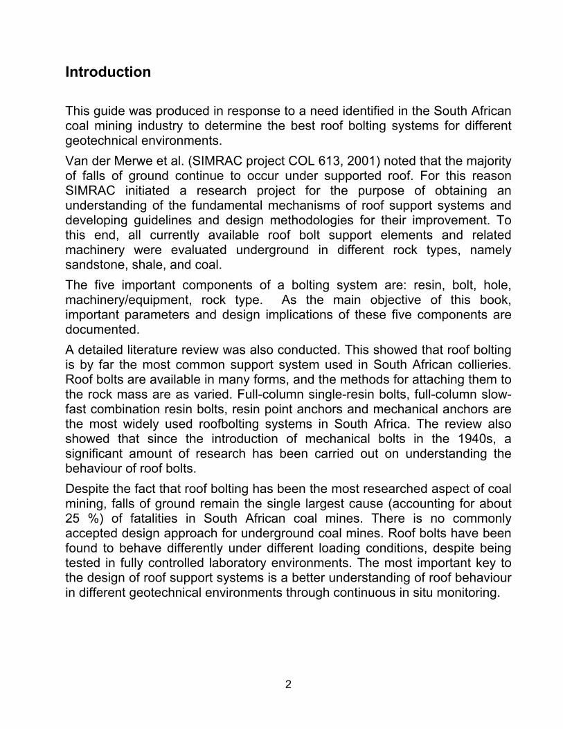
Figure 2-2 SEPT installed over roof bolt
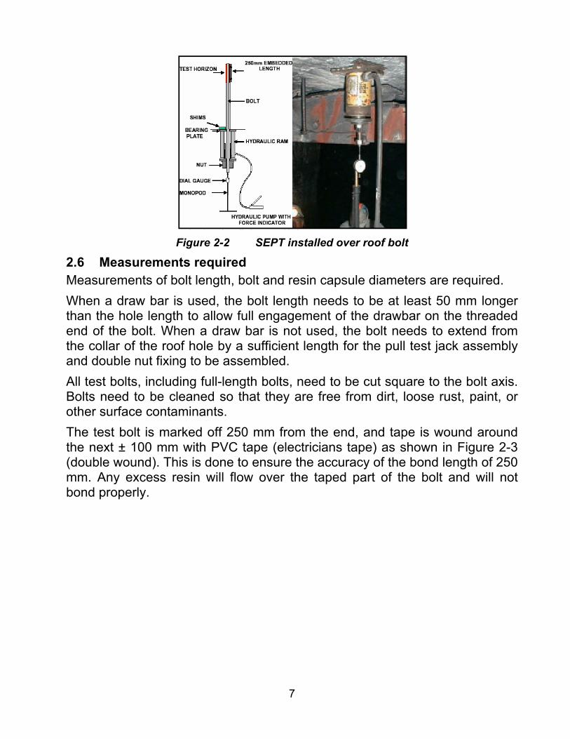
2.6 Measurements required Measurements of bolt length, bolt and resin capsule diameters are required. When a draw bar is used, the bolt length needs to be at least 50 mm longer than the hole length to allow full engagement of the drawbar on the threaded end of the bolt. When a draw bar is not used, the bolt needs to extend from the collar of the roof hole by a sufficient length for the pull test jack assembly and double nut fixing to be assembled. All test bolts, including full-length bolts, need to be cut square to the bolt axis. Bolts need to be cleaned so that they are free from dirt, loose rust, paint, or other surface contaminants. The test bolt is marked off 250 mm from the end, and tape is wound around the next ± 100 mm with PVC tape (electricians tape) as shown in Figure 2-3 (double wound). This is done to ensure the accuracy of the bond length of 250 mm. Any excess resin will flow over the taped part of the bolt and will not bond properly.

8
Figure 2-3 Bolt preparation
Using a Vernier Caliper the bolt diameter must be measured in detail, both over the ribs and the core of the bolt, and recorded on the log sheet. The bolt must be suitably marked. Using either a Vernier Caliper or a Go/No-go gauge the resin diameter must be recorded and the capsules marked accordingly. Note that it is recommended that a new drill bit of the specified type be used for each test. Also, the same drilling machine and operator needs to be used throughout the tests. The width of the tip of the bit must be measured with a Vernier Caliper. The degree of reaming in the hole can be quantified through these measurements. The hole debris clearance system normally used for bolt installation must be used to clean the installation hole. Holes must be drilled to the required depth, by first marking the drill steel. The hole depth must be checked after drilling, with the use of the test bolt (Sections 2.8 and 2.9). After the holes have been drilled, the inside diameter of the drilled hole is measured, at intervals along the back 250 mm of the hole, with a borehole micrometer. A minimum of four measurements are required, over the 250 mm distance, as shown in Figure 2-4. These measurements are averaged. This procedure is repeated for each hole drilled.

9
Figure 2-4 Borehole micrometer for measuring borehole diameter
2.7 Capsule preparation and measurement of embedment length The required length of capsule is calculated through the use of equation 2-1:
)mm(lengthBondx)mm(diasinRe
)mm(diaBolt)mm(diaHolelengthCapsule 2
22 −= [2-1]
taking Bond length as 250 mm. Add 10 mm to the capsule length to allow for irregular capsule ends. Test resin capsules of the calculated length are prepared from the resin used in the heading, using cable ties, as illustrated in Figure 2-5 and Figure 2-6.
Figure 2-5 Resin preparation
10
Figure 2-6 Resin pill resizing
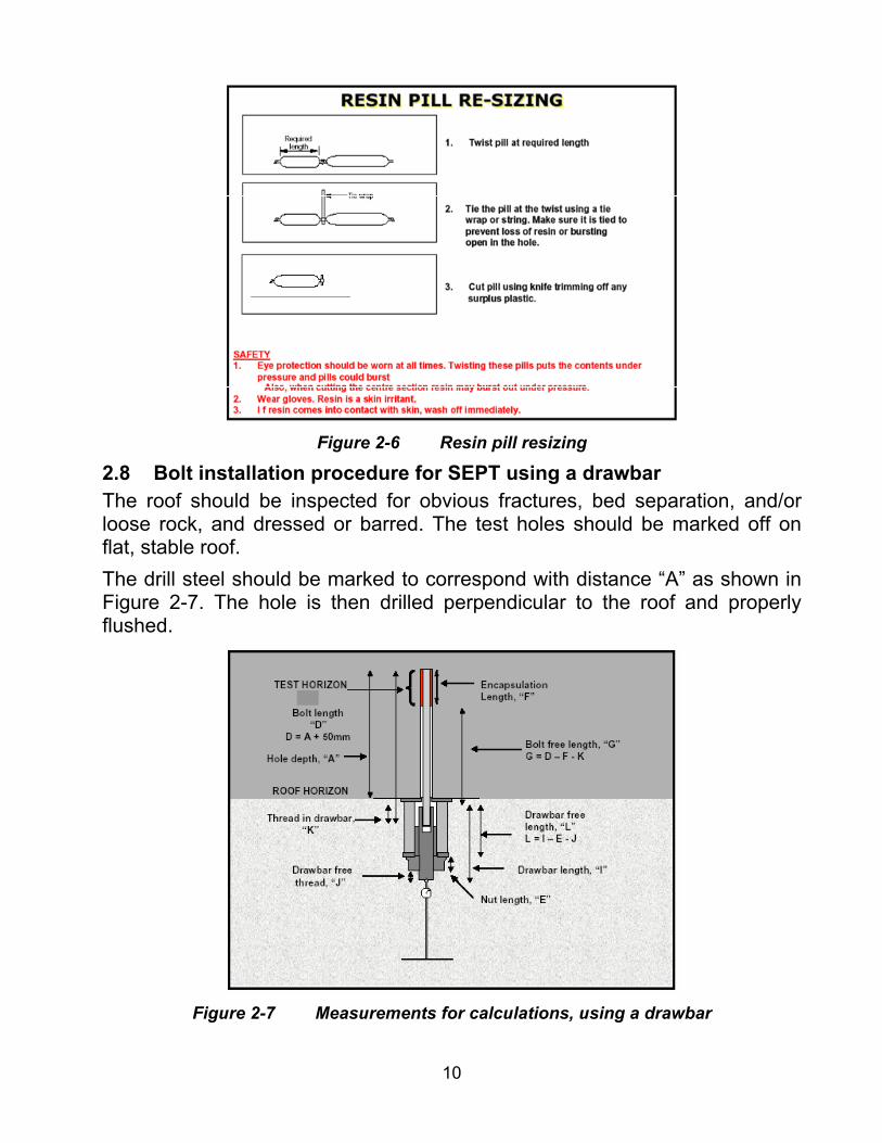
2.8 Bolt installation procedure for SEPT using a drawbar The roof should be inspected for obvious fractures, bed separation, and/or loose rock, and dressed or barred. The test holes should be marked off on flat, stable roof. The drill steel should be marked to correspond with distance “A” as shown in Figure 2-7. The hole is then drilled perpendicular to the roof and properly flushed.
Figure 2-7 Measurements for calculations, using a drawbar

11
At this point all necessary measurements (as described in Section 2.6) should be made. When the bolt is inserted into the back of the hole, ± 50 mm must protrude from the bottom of the hole to allow the drawbar to be safely attached to the bolt. The resin cartridge and bolt should be inserted by hand to ensure that no damage occurs to the cartridge during installation. The machine is then raised to the bolt and the bolt engaged in the chuck adaptor. The bolt and capsule are accurately positioned using the depth mark on the bolt to indicate when the resin capsule is at the back of the hole. The machine is activated and the bolt spun for the instructed period as per normal installation of bolt. The spin period is timed and recorded on the log sheet. The bolt is held for the instructed period. Note the bolt is not pre-tensioned through breaking out the shear pin. The roofbolter spanner is removed and the resin allowed to cure for at least one hour, but for no more than 24 hours.
2.9 Bolt installation procedure for SEPT without drawbar As per the drawbar installation, the roof should be inspected and an appropriate site selected. The drill steel should be marked to correspond with distance “A” as shown in Figure 2-8. The hole is then drilled and appropriate measurements are made.
Figure 2-8 Measurements for calculations, no drawbar
After drilling ensure the hole is properly flushed. Make all the necessary measurements pertaining to the hole, as described in Section 2.6. The bolt is inserted to the back of the hole, with length “B” equal to the length of the hydraulic ram, the two backing plates and ±60 mm to attach a double lock-nut to keep the hydraulic ram in place. The thickness of the two nuts
12
(length “E”) and 50 mm for the thread-free length (length “C”) should be allowed for. The resin capsule and bolt are then inserted into the hole, and the installation completed as described above.
2.10 Procedure for pulling the installed roof bolts Bolts need to be pulled no sooner than one hour and no later than 24 hours after installation. This is to ensure that the resin has time to cure and that no time-dependent roof movement mechanically locks the bolt in the hole. The pull test jack and bearing plates and, where applicable, the drawbar, are assembled as shown in Figure 2-1 and Figure 2-2. The ram is aligned along the axis of the bolt ensuring that the bolt is not in contact with the wall of the hole. To achieve this, any loose material is trimmed from around the mouth of the hole (where necessary) and the assembly is aligned by placing steel shims between the roof and bearing plate. The bolt must not be in contact with the shims or bearing plates as this will affect the result. The dial gauge is set directly below the safety nut or in the indentation in the pull bar, and secured. When the assembly is fully aligned, the stem of the dial gauge is located into the indentation on the end of the draw bar so that it is also in line with the bolt axis. Where a draw bar is not used, a dial gauge locator nut is fixed to the end of the bolt. The foot of the monopod should be located on a firm surface. The axis of bolt, dial gauge, ram and monopod should be in line to ensure that load is applied axially to the bolt. The dial is set to zero and initial readings on the dial gauge and pressure gauge recorded. At least two skilled operators are required to carry out the tests, one of whom needs to operate the pump and read the pressure gauge and the other reads the dial gauge. To ensure safety, the operator should stand clear from the pulling equipment and start applying slow steady continuous pressure using the hand pump. The load should be applied slowly and smoothly and without pause. The strength of the bolt should not be exceeded to prevent violent failure of the steel and possible accidents. The bolt displacement from the dial gauge is recorded every 10 kN until maximum pressure is reached, or the bond fails. Bond failure is indicated by a significant movement on the dial gauge for no appreciable increase in force, i.e. one revolution/sweep for 10 kN force increase. The load should not exceed 100 kN (10 tons) for 16 mm bolts and 150 kN (15 tons) for 20 mm bolts. All relevant information can be captured on a pull test data-recording sheet, as presented in Table 2-1.

13
Table 2-1 Short encapsulation pull test log sheet PULL TEST RESULTS COLLIERY SECTION DATE
MM Bit type Bit O mmRoof Horizon (measured from top of seam)
Bolt Lengthmm
1 2 3 4 5 6 7 8 9 10 11 12 0 210
kN 1
34
65
789
1011
Installation time Pull out time
Bolt rib Bolt core Hole Resin Resin SpareO O O capsule O length Thread
(mm) (mm) (mm) (mm) (mm) ( mm)
Remarks:
2030405060708090100110120130140150160170180190200210220
12
Test Details :
PULL TEST RESULTS COLLIERY SECTION DATE
MM Bit type Bit O mmRoof Horizon (measured from top of seam)
Bolt Lengthmm
1 2 3 4 5 6 7 8 9 10 11 12 0 210
kN 1
34
65
789
1011
Installation time Pull out time
Bolt rib Bolt core Hole Resin Resin SpareO O O capsule O length Thread
(mm) (mm) (mm) (mm) (mm) ( mm)
Remarks:
2030405060708090100110120130140150160170180190200210220
12
Test Details :

14
2.11 Calculation of bond shear strength A graph of applied force (kN) vs. bond displacement needs to be plotted to calculate the bond strength and system stiffness from the mean of three tests. The bond strength is taken as the applied force at which the slope of the graph falls below 20 kN/mm – Figure 2-9. The bond displacement is calculated using the following equation:
)( drawbarboltmeasuredbond ElongationElongationdd +−= [2-2]The bolt and/or draw bar extension is calculated as follows:
2
4π
⋅=bolt
s
F LFElongationE D [2-3]
where F = Applied Force (N), LF = Bolt free length (mm) = bolt length - (encapsulated length + length in pull bar), ES = Young's Modulus for steel = 206000 MPa, D = Nominal bolt diameter (mm). When failure occurs on the resin/rock interface, the bond shear strength can be expressed as a contact shear strength or bond stress through:
πτ
bondbond
bondbond Lengthdia
F= [2-4]
2.12 Calculation of grip factor The ‘grip factor’ can also be used to express the bond strength. Grip factor (bond strength) is measured through short encapsulation pull tests (SEPT). Grip factor (bond strength, in kN/mm) (BS) is defined as:
)mm(LengthBond)kN(LoadMaximumBS = [2-5]
2.13 Calculation of support system stiffness Stiffness is a measure of how quickly a support develops its load-carrying capacity in response to dilation or bed separation in the roof strata. Stiffness (K) can be obtained from the load-deformation curves of SEPT and should be measured between 40 and 80 kN applied loads, Figure 2-9, as:
dLK
∆∆
= [2-6]
The stiffness increases with increasing area (bolt diameter) and material modulus (steel modulus) and decreases with increasing length. Overall stiffness is also affected by resin/rock types, and by wet/dry drilling. It should be noted that, with a conventional point-anchor mechanical roof bolt, the bolt is anchored only at the top, and the ‘free length’ of the bolt is the entire length

15
of the bolt less the anchored length. In full-column resin bolts, the ‘free length’ of the bolt is less, and full-column roof bolts hence provide stiffer support than mechanical bolts (Mark, 2000). It should be noted that the roof experiences some creep in the period from mining to support installation. Although this effect was measured to be insignificant (Canbulat and Jack, 1998), this phenomenon has not yet been fully quantified.
Resin 1 30 Sec
0
20
40
60
80
100
120
140
0 1 2 3 4 5 6 7 8 9 10
Displacement (mm)
Load
(kN
)
α1
Resin 1 30 Sec
0
20
40
60
80
100
120
140
0 1 2 3 4 5 6 7 8 9 10
Displacement (mm)
Load
(kN
)
α1α1
Figure 2-9 Calculation of stiffness of roof bolting system. Max load in this
example is approximately 100 kN (slope becomes < 20 kN/mm). Table 2-2 give the suggested roof bolt stiffness for South African collieries. These values were obtained from extensive underground measurements and testing.
Table 2-2 Required support stiffnesses for different bolting types
Bolt type Required Support Stiffness for Non-
tensioned bolts (kN/mm)
20 mm 60 18 mm 50 16 mm 40
Note that the yielding loads of bolts are calculated according to a minimum steel strength of 480 MPa.
16
2.14 Simplified SEPT procedure For the routine monitoring of roofbolts in a production environment, SEPT can be a lengthy and time consuming process. A simplified SEPT procedure is outlined in this section for use in routine monitoring, once the characteristics of the roofbolting system have been established. This enables the user to dispense with taking measurements regarding the diameters of the bolt, resin capsule and hole, as these will have been determined at the design stage. As with the standard SEPT, bolts are cleaned of excess dirt or other surface contaminants. The bolt is then measured 250 mm from the end, and tape is double wound around the next 150 mm, as in Figure 2-3. This will prevent any excess resin from properly bonding to the bolt. Test holes should be checked using a bolt to verify they are at the required length. It is suggested that an initial calculation for the length of the resin capsule, based upon the anticipated bolt, capsule and hole diameters, is made on surface prior to testing. All resin capsules can then be prepared to this length. Bolt installation and pulling procedures are carried out as for the standard SEPT procedures described in sections 2.8, 2.9 and 2.10.
3 Specifications for roofbolters 3.1 Introduction The quality of installation of a support system is directly related to the performance of the equipment that is used to install the bolts. Performance of bolting equipment was therefore investigated as part of this study. The following parameters were assessed: Free rotation speed (rpm); Drilling speed (rpm); Spinning speed (rpm); Torque (Nm); Thrust (kN); and Hole profile for various combinations. It should be noted that currently in South Africa, there are no standards for these parameters in collieries, except the torque, which should be 240 Nm in order to generate 50 kN (5 tonnes) for tensioning by roofbolters. A total of 143 roofbolters, which were operational during the evaluation, were tested from 27 different collieries, ranging from Tshikondeni in the north to Zululand Anthracite Colliery in the south. This provided a comprehensive database of roof bolter information. Tests were done on a variety of machines from different manufacturers, along with a number of custom-designed bolters. Results from these machines varied widely, even to the extent of differing from boom to boom on twin boom machines.
17
3.2 Testing procedure During this investigation, the testing procedure for each machine followed a set pattern which was developed to be as quick and easy as possible, in this way minimizing any possible downtime to production machines. For each machine, the torque setting at which the machine spins the bolt was measured, to ensure that the machine was capable of breaking out either the crimp or shear pin of the bolt, if such a feature was present. Following this, a hole was drilled and the speed of drilling was measured in revolutions per minute using a laser digital tachometer. This device quickly and easily measures the speed after simply attaching a reflective strip to the drill chuck or drill steel, and shining the laser onto the strip while the drilling is in progress. Once the hole was drilled, the depth was measured and a borehole micrometer was inserted to measure the hole diameter at intervals along the length of the hole. This gave an indication of the hole profile as drilled by the particular bit type at a specific rotation speed. Measurements were taken from two to three holes per roofbolter. A bolt was then inserted into the chuck and a load cell fitted over the bolt. The bolt was pushed into the hole, without inserting resin, and pushed against the roof with the maximum force possible to establish the thrust that the roof bolter was capable of exerting against the bolt, which is important when full-column roof bolts are being installed and a bolt is being pushed through several resin capsules. The bolt was then installed with resin and a speed measurement was taken while the bolt was being spun through the resin. This measurement showed the speed at which the resin was being mixed. Finally, the maximum free rotation speed of the drill chuck was measured as a comparison to the other speeds measured. The form, presented in Figure 3-1 was used to record measurements during the testing. Other measurements taken were standard lengths and diameters, the bit type and diameter, drill steel length and diameter, type of bolt, bolt length and diameter. The type of support, be it mechanical point anchor, resin point anchor or full-column resin was noted; and resin type, capsule length and diameter recorded. Finally, drilling type (wet or dry) was noted, as this affects the hole profile in different rock types. Where possible, a borehole log of the area in which tests were conducted was collected in order to take into account the influence of the immediate roof in which installation was taking place.
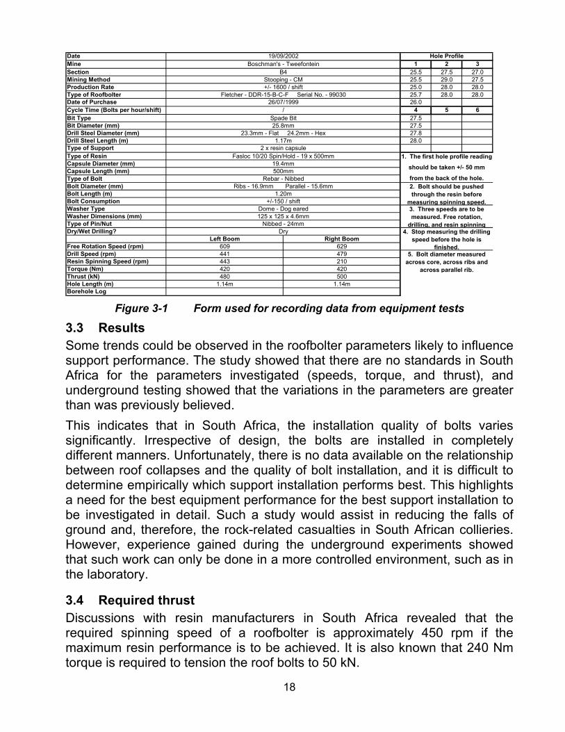
18
DateMine 1 2 3Section 25.5 27.5 27.0Mining Method 25.5 29.0 27.5Production Rate 25.0 28.0 28.0Type of Roofbolter 25.7 28.0 28.0Date of Purchase 26.0Cycle Time (Bolts per hour/shift) 4 5 6Bit Type 27.5Bit Diameter (mm) 27.5Drill Steel Diameter (mm) 27.8Drill Steel Length (m) 28.0Type of SupportType of ResinCapsule Diameter (mm)Capsule Length (mm)Type of BoltBolt Diameter (mm)Bolt Length (m)Bolt ConsumptionWasher TypeWasher Dimensions (mm)Type of Pin/NutDry/Wet Drilling?
Left Boom Right BoomFree Rotation Speed (rpm) 609 629Drill Speed (rpm) 441 479Resin Spinning Speed (rpm) 443 210Torque (Nm) 420 420Thrust (kN) 480 500Hole Length (m) 1.14m 1.14mBorehole Log
1. The first hole profile reading
should be taken +/- 50 mm
from the back of the hole.
5. Bolt diameter measured across core, across ribs and
across parallel rib.
2. Bolt should be pushed through the resin before
measuring spinning speed.3. Three speeds are to be measured. Free rotation,
drilling, and resin spinning 4. Stop measuring the drilling
speed before the hole is finished.
Hole Profile
125 x 125 x 4.6mmNibbed - 24mm
Dry
Ribs - 16.9mm Parallel - 15.6mmRebar - Nibbed
1.20m+/-150 / shift
Dome - Dog eared
2 x resin capsuleFasloc 10/20 Spin/Hold - 19 x 500mm
19.4mm500mm
Spade Bit25.8mm
23.3mm - Flat 24.2mm - Hex1.17m
+/- 1600 / shiftFletcher - DDR-15-B-C-F Serial No. - 99030
26/07/1999/
19/09/2002Boschman's - Tweefontein
B4Stooping - CM
Figure 3-1 Form used for recording data from equipment tests
3.3 Results Some trends could be observed in the roofbolter parameters likely to influence support performance. The study showed that there are no standards in South Africa for the parameters investigated (speeds, torque, and thrust), and underground testing showed that the variations in the parameters are greater than was previously believed. This indicates that in South Africa, the installation quality of bolts varies significantly. Irrespective of design, the bolts are installed in completely different manners. Unfortunately, there is no data available on the relationship between roof collapses and the quality of bolt installation, and it is difficult to determine empirically which support installation performs best. This highlights a need for the best equipment performance for the best support installation to be investigated in detail. Such a study would assist in reducing the falls of ground and, therefore, the rock-related casualties in South African collieries. However, experience gained during the underground experiments showed that such work can only be done in a more controlled environment, such as in the laboratory.
3.4 Required thrust Discussions with resin manufacturers in South Africa revealed that the required spinning speed of a roofbolter is approximately 450 rpm if the maximum resin performance is to be achieved. It is also known that 240 Nm torque is required to tension the roof bolts to 50 kN.

19
The following approximate relationship was established through linear regression analysis of the measured data:
FRS0.26 TOR0.24 THR0.44 = 60 [3-1]where FRS=free rotation speed (rpm), TOR =torque (kN), THR = thrust (kN). From this formula it can be concluded that if the required torque is 240 kN (to apply 50 kN tension on installed bolts), and the required free rotation speed is 450 rpm (as recommended by the resin manufacturers), approximately 15 kN thrust will be required on the drill bit.
3.5 Wet and dry drilling A total of 24 short encapsulated pull tests were conducted to determine the effect of wet and dry drilling. These tests were conducted using the same roofbolter, for three different resin types from the same Manufacturer “B”; namely 15-second resin, 30-second resin and 5/10-minute resin. Figure 3-2 shows the average bond strengths achieved for different resin types using wet and dry drilling. This figure indicates that bond strengths for wet drilling are between 4 to 28 per cent greater than with dry drilling, probably due to the fine particles which may be left behind after dry drilling.
0.00
0.05
0.10
0.15
0.20
0.25
0.30
0.35
0.40
0.45
0.50
15sec resin 60sec resin 5/10min resin
Bon
d St
reng
th (k
N/m
m)
Vacuum
Wet
Figure 3-2 Effect of wet-dry drilling on bond strength
Figure 3-3 shows the overall stiffnesses achieved when wet and dry drilling is used for different resins. As can be seen, the overall stiffnesses are significantly greater for wet drilling than for dry drilling for the faster speed resin types.
20
0.00
20.00
40.00
60.00
80.00
100.00
120.00
140.00
15sec resin 60sec resin 5/10min resin
Ove
rall
Stiff
ness
(kN/
mm
)VacuumWet
Figure 3-3 Effect of wet and dry drilling on overall support stiffness
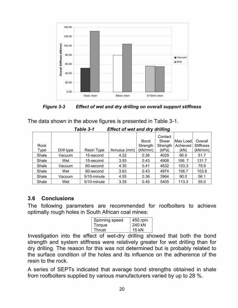
The data shown in the above figures is presented in Table 3-1.
Table 3-1 Effect of wet and dry drilling
Rock Type Drill type Resin Type Annulus (mm)
Bond Strength (kN/mm)
Contact Shear
Strength (kPa)
Max Load Achieved
(kN)
Overall Stiffness (kN/mm)
Shale Vacuum 15-second 4.22 0.36 4029 90.0 51.7 Shale Wet 15-second 3.93 0.43 4908 106. 7 131.7 Shale Vacuum 60-second 4.30 0.41 4632 103.3 79.9 Shale Wet 60-second 3.63 0.43 4974 106.7 103.8 Shale Vacuum 5/10-minute 4.55 0.36 3964 90.0 56.1 Shale Wet 5/10-minute 3.35 0.45 5405 113.3 55.0
3.6 Conclusions The following parameters are recommended for roofbolters to achieve optimally rough holes in South African coal mines:
Spinning speed 450 rpm Torque 240 kN Thrust 15 kN
Investigation into the effect of wet-dry drilling showed that both the bond strength and system stiffness were relatively greater for wet drilling than for dry drilling. The reason for this was not determined but is probably related to the surface condition of the holes and its influence on the adherence of the resin to the rock. A series of SEPTs indicated that average bond strengths obtained in shale from roofbolters supplied by various manufacturers varied by up to 28 %.

21
4 Performance of roof bolts 4.1 Performance of roof bolts manufactured in South Africa A total of 61 short encapsulated pull tests were conducted on 20 mm roof bolts to determine the performance of bolts obtained from four manufacturers, and the results are shown in Figure 4-1. As can be seen, bolts from all four manufacturers showed almost identical results in sandstone, while in other rock types the results were dissimilar. The figure also indicates that bolts from Manufacturer “A” performed slightly better in shale, while manufacturer “B” performed slightly better in coal than those from the other manufacturers.
0.00
0.10
0.20
0.30
0.40
0.50
0.60
0.70
Manufacturer "A" Manufacturer "B" Manufacturer "C" Manufacturer "D"
Bond
Stre
ngth
(kN/
mm
)
ShaleSandstoneCoal
Figure 4-1 Performance of roof bolts determined from underground SEPTs
4.2 Tensioned versus non-tensioned roof bolts An additional 25 short encapsulated pull tests were conducted to determine the effect of tensioning on bond strength. These tests were performed in sandstone and shale roofs, and the results are given in Figure 4-2. Non-tensioned roof bolts achieved significantly greater bond strengths than the tensioned bolts. Similarly, Figure 4-3 shows that non-tensioned roof bolts achieved significantly higher system stiffnesses than the tensioned roof bolts.

22
0.0
0.1
0.2
0.3
0.4
0.5
0.6
0.7
Sandstone Shale
Bond
Stre
ngth
(kN/
mm
)UntensionedTensioned
Figure 4-2 Effect of tensioning on bond strength
0.0
20.0
40.0
60.0
80.0
100.0
120.0
140.0
Sandstone Shale
Ove
rall
Stiff
ness
(kN/
mm
)
UntensionedTensioned
Figure 4-3 Effect of tensioning on overall stiffness
It is thought that with SEPTs of tensioned bolts, because the bond length is only 250 mm the bonding can easily be damaged when the bolt is being tensioned. For this reason it is probable that the test results obtained do not give a fair reflection of the performance of full-column tensioned bolts, and an improved testing procedure therefore needs to be developed.
4.3 Variation in roof bolt parameters In a support system, it may not be possible to control the hole diameter, because of many factors such as the rock strength, bit type, drilling type, roofbolter thrust etc. However, it is possible to control the bolt diameter and
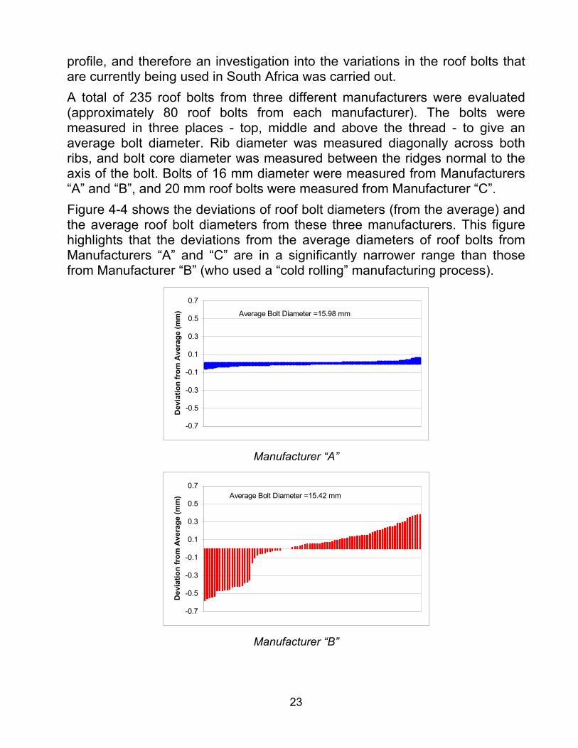
23
profile, and therefore an investigation into the variations in the roof bolts that are currently being used in South Africa was carried out. A total of 235 roof bolts from three different manufacturers were evaluated (approximately 80 roof bolts from each manufacturer). The bolts were measured in three places - top, middle and above the thread - to give an average bolt diameter. Rib diameter was measured diagonally across both ribs, and bolt core diameter was measured between the ridges normal to the axis of the bolt. Bolts of 16 mm diameter were measured from Manufacturers “A” and “B”, and 20 mm roof bolts were measured from Manufacturer “C”. Figure 4-4 shows the deviations of roof bolt diameters (from the average) and the average roof bolt diameters from these three manufacturers. This figure highlights that the deviations from the average diameters of roof bolts from Manufacturers “A” and “C” are in a significantly narrower range than those from Manufacturer “B” (who used a “cold rolling” manufacturing process).
-0.7
-0.5
-0.3
-0.1
0.1
0.3
0.5
0.7
Dev
iatio
n fr
om A
vera
ge (m
m) Average Bolt Diameter =15.98 mm
Manufacturer “A”
-0.7
-0.5
-0.3
-0.1
0.1
0.3
0.5
0.7
Dev
iatio
n fr
om A
vera
ge (m
m) Average Bolt Diameter =15.42 mm
Manufacturer “B”
24
-0.7
-0.5
-0.3
-0.1
0.1
0.3
0.5
0.7
Dev
iatio
n fr
om A
vera
ge (m
m) Average Bolt Diameter =20.01 mm
Manufacturer “C”
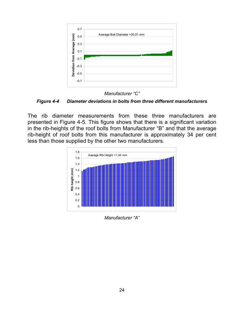
Figure 4-4 Diameter deviations in bolts from three different manufacturers The rib diameter measurements from these three manufacturers are presented in Figure 4-5. This figure shows that there is a significant variation in the rib-heights of the roof bolts from Manufacturer “B” and that the average rib-height of roof bolts from this manufacturer is approximately 34 per cent less than those supplied by the other two manufacturers.
0
0.2
0.4
0.6
0.8
1
1.2
1.4
1.6
1.8
Rib
hei
ght (
mm
)
Average Rib Height =1.44 mm
Manufacturer “A”

25
0
0.2
0.4
0.6
0.8
1
1.2
1.4
1.6
1.8
2
Rib
hei
ght (
mm
)
Average Rib Height =1.07 mm
Manufacturer “B”
0
0.2
0.4
0.6
0.8
1
1.2
1.4
1.6
1.8
2
Rib
hei
ght (
mm
)
Average Rib Height =1.36 mm
Manufacturer “C”
Figure 4-5 Rib-height measurements in bolts from three different manufacturers The effect of annulus size on support performance has been shown to be significant. Also, theoretically, a 0.6 mm reduction in bolt diameter will reduce the yield load of a 16 mm bolt by 7 per cent. This highlights the need for quality control procedures to be in place at mines for checking the elements of a support system, which are themselves part of the engineering design (roof bolt, bits etc.). An attempt was also made to determine the rib thickness, the spacing between the ribs, and the angle of the ribs of currently used roof bolts in South Africa. Approximately 30 roof bolts from four different suppliers were obtained and three measurements were taken for each bolt. The average results obtained from each manufacturer are shown in Table 4-1.

26
Table 4-1 Rib thickness, spacing and angle measured on S. African roof bolts
Bolt Manufacturer
Rib thickness (mm)
Spacing between the ribs (mm)
Rib angle (degree)
"A" 3.88 8.70 64 "B" 3.02 7.33 70 "C" 3.47 10.79 63 "D" 3.04 9.40 60
Average 3.35 9.06 64.3 As can be seen from this table, there are differences between the parameters that determine the bolt profile in South African roof bolts. Figure 4-6 illustrates the visual appearance of bolts from the four different manufacturers.
“D”“C”“B”“A”
6 8 6 7
“D”“C”“B”“A”
6 8 6 7
Figure 4-6 Visual illustration of four South African roof bolts
Although there are small differences between the South African roof bolts tested, there is a significant visual difference between the AT bolt from the UK and typical South African bolts (Figure 4-7). The angle of ribs between the two types of bolt is significantly different. A detailed sensitivity analysis to the various parameters should be conducted on the resin that would be used and the rock types in which it would be installed in South African collieries.

27
AT BoltFrom UK
South African Bolt (“D”)
AT BoltFrom UK
South African Bolt (“D”)
Figure 4-7 Visual comparison of UK and South African bolts Roofbolting should be considered as a system and the design of elements comprising the system should be such that the difference in strength between the weakest and strongest element is minimised.
4.4 Effect of hot and cold rolling of bolts At high temperatures, the strength values (yield stress, proof stress, and tensile strength) of metals temporarily decrease and they become "softer". Also, the possible plasticity at higher temperatures is greater, as a rule, and the metal becomes more ductile. This change of properties with rising temperatures is used for the hot forming of steel. In general, the temperature for hot forming is higher than the re-crystallisation temperature of the steel. The resulting advantages of hot forming include:
• Improved formability of the work piece. • Less force required during manufacture. • Large degree of possible deformation in one step, resulting in a
reduction of processing time. • Beneficial effect on the structure and the properties of the work piece. • Little or no work hardening (if not desired).
Some disadvantages of hot forming are: • High resource input and related costs for heating the steel in
relation to the energy required for forming. • Inevitable formation of hard and brittle scale on the surface of
the work piece and related tool wear.
28
• Reduced standing time of tools due to the thermal load and increased wear.
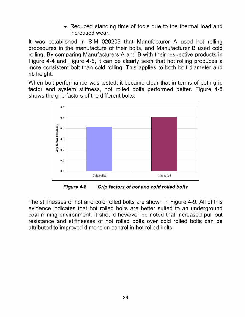
It was established in SIM 020205 that Manufacturer A used hot rolling procedures in the manufacture of their bolts, and Manufacturer B used cold rolling. By comparing Manufacturers A and B with their respective products in Figure 4-4 and Figure 4-5, it can be clearly seen that hot rolling produces a more consistent bolt than cold rolling. This applies to both bolt diameter and rib height. When bolt performance was tested, it became clear that in terms of both grip factor and system stiffness, hot rolled bolts performed better. Figure 4-8 shows the grip factors of the different bolts.
0.0
0.1
0.2
0.3
0.4
0.5
0.6
Cold rolled Hot rolled
Gri
p fa
ctor
(kN
/mm
)
Figure 4-8 Grip factors of hot and cold rolled bolts
The stiffnesses of hot and cold rolled bolts are shown in Figure 4-9. All of this evidence indicates that hot rolled bolts are better suited to an underground coal mining environment. It should however be noted that increased pull out resistance and stiffnesses of hot rolled bolts over cold rolled bolts can be attributed to improved dimension control in hot rolled bolts.

29
0.0
20.0
40.0
60.0
80.0
100.0
120.0
Cold rolled Hot rolled
Ove
rall
stiff
ness
(kN
/mm
)
Figure 4-9 Stiffness of hot and cold rolled bolts
4.5 Shear strength of bolts The shear strength of roofbolts is an important aspect in the beam building method of roof support as the bolts generate shear resistance to the movement of the beams within the roof unit. A number of tests were performed at the testing facility of the CSIR using a 30 second resin with a 20 mm diameter bolt. The bolt and resin were mixed at a speed of 185 RPM and installed into a 28 mm diameter mild steel tube. A groove was then cut into the centre of the tube to provide a shear plane and lessen the effect of the tube upon the test results. The bolt was then inserted into the shear test rig in preparation for testing. The inserts in the rig which provided the shear plane were made of heat toughened steel. The test rig was then inserted into the Terratek test rig and loaded until failure. A total of 10 samples were tested and a set of very consistent results was attained. The results can be seen in Table 4-2.
Table 4-2 Load (kN) Displacement (mm) Average 213.3 16.4 Maximum 226.0 19.0 Minimum 205.0 15.0 Standard Deviation 7.0 1.6
The results indicate that the average shear strength of a full column resin bolt is slightly more than 210 kN and the displacement is just over 16 mm.

30
Ultimate tensile tests performed at CSIR Miningtek on 20 mm roof bolts indicated that the tensile strength is approximately 240 kN. From these results, it is possible to establish that the shear strength of a full column resin bolt is 89 per cent of the ultimate tensile strength.
5 Performance of resin 5.1 Performance of resin manufactured in South Africa A total of 132 short encapsulated pull tests were conducted to determine the performance of various resin types obtained from two manufacturers, namely Manufacturer “A” and Manufacturer “B”. The results from these tests in three different rock types are shown in Figure 5-1, Figure 5-2 and Figure 5-3. These figures indicate that, in sandstone, 15 second and 30 second resin types from the two different manufacturers performed similarly. However, the performance of slow 5/10-minute resins from both manufacturers was much lower than that of the fast resins.
0.00
0.10
0.20
0.30
0.40
0.50
0.60
0.70
15 second 30 second 5/10 min
Bon
d St
reng
th (k
N/m
m)
Manufacturer "A"Manufacturer "B"
Sandstone
Figure 5-1 Performance of 15-second, 30-second and 5/10 min resin types in
sandstone from both resin manufacturers No trend could be observed in comparing the resin performances in coal and shale.

31
0.00
0.10
0.20
0.30
0.40
0.50
0.60
0.70
15s 30s
Bond
Str
engt
h (k
N/m
m)
Manufacturer "A"Manufacturer "B"
Shale
Figure 5-2 Performance of 15-second and 30-second resin types in shale from
both resin manufacturers
0.00
0.10
0.20
0.30
0.40
0.50
0.60
0.70
15s 30s
Bon
d St
reng
th (k
N/m
m)
Manufacturer "A"
Manufacturer "B"
Coal
Figure 5-3 Performance of 15-second and 30-second resin types in coal from
both resin manufacturers An analysis of the system stiffness of both resin types from both manufacturers was also conducted. The results are shown in Figure 5-4.

32
0
20
40
60
80
100
120
140
160
180
Sandstone Shale Coal
Ove
rall
Stif
fnes
s (k
N/m
m)
15s Manufacurer "A"
30s Manufacurer "A"
15s Manufacurer "B"
30s Manufacurer "B"
Figure 5-4 System stiffness of 15-second and 30-second resin types from both
resin manufacturers Figure 5-4 indicates that both 15-second and 30-second resins from Manufacturer “A” achieved higher stiffness than those from Manufacturer “B” in sandstone and coal. In shale, both resins from both manufacturers performed in a similar manner.
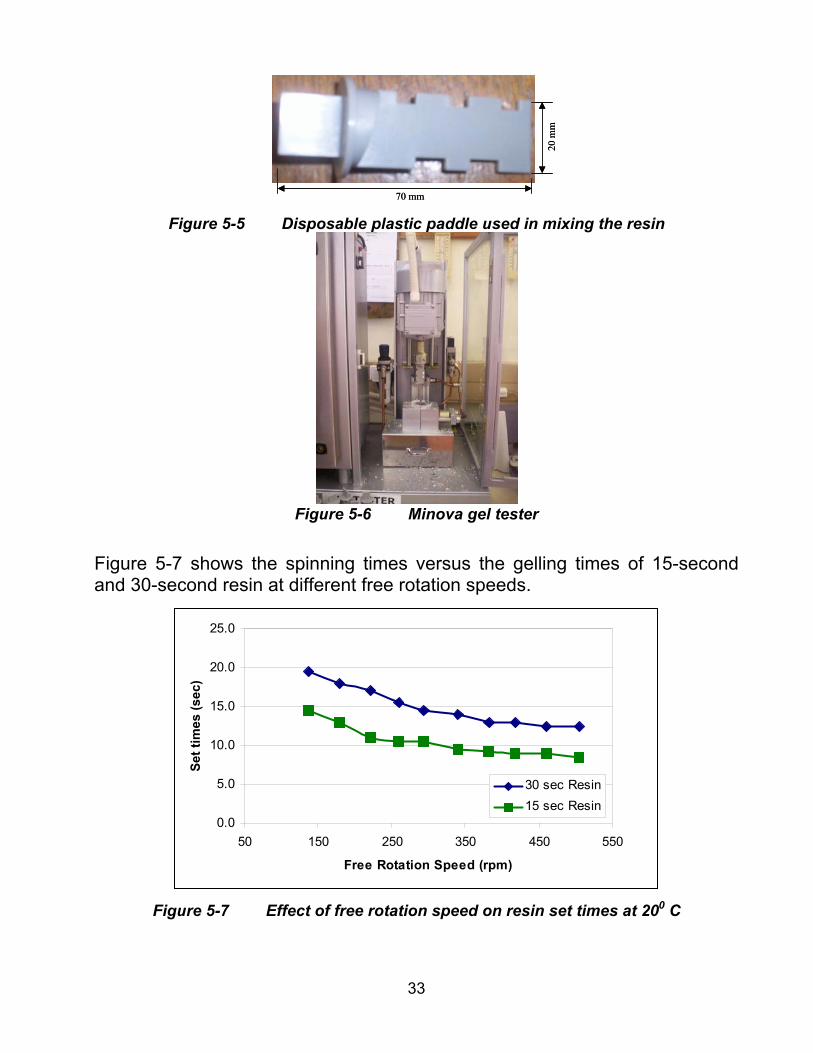
5.2 Effect of spinning speed on resin setting In order to determine the effect of spinning speed on resin setting times, a series of tests was conducted at the Minova (South Africa) laboratory. The Minova gel tester comprises an electric motor attached to a spinning arm. Into this arm is inserted a disposable plastic paddle. The arm is then lowered into a hand-prepared resin/catalyst sample and spun. The electric current used by the motor is monitored throughout the spinning process. As the resin gels, the resistance to the motor increases, with a resultant increase in the required current. At a preset current (in milliamps) the resin is deemed to have set and the test is complete. A plot of mA versus time is then interpreted to determine the gelling time of the sample. The current to the motor in the gel tester is controllable and the spinning speed is directly related to this. In the Minova laboratory tests the free rotation speed of the motor was measured at different settings in order that the relationship between current and spinning speed could be established. The free rotation speed is the speed of the motor when it is not under load. Once this was established, tests were performed using Minova’s 15 and 30 second resins at various spinning speeds.
33
70 mm
20 m
m
70 mm
20 m
m
Figure 5-5 Disposable plastic paddle used in mixing the resin
Figure 5-6 Minova gel tester
Figure 5-7 shows the spinning times versus the gelling times of 15-second and 30-second resin at different free rotation speeds.
0.0
5.0
10.0
15.0
20.0
25.0
50 150 250 350 450 550
Free Rotation Speed (rpm)
Set t
imes
(sec
)
30 sec Resin15 sec Resin
Figure 5-7 Effect of free rotation speed on resin set times at 200 C
34
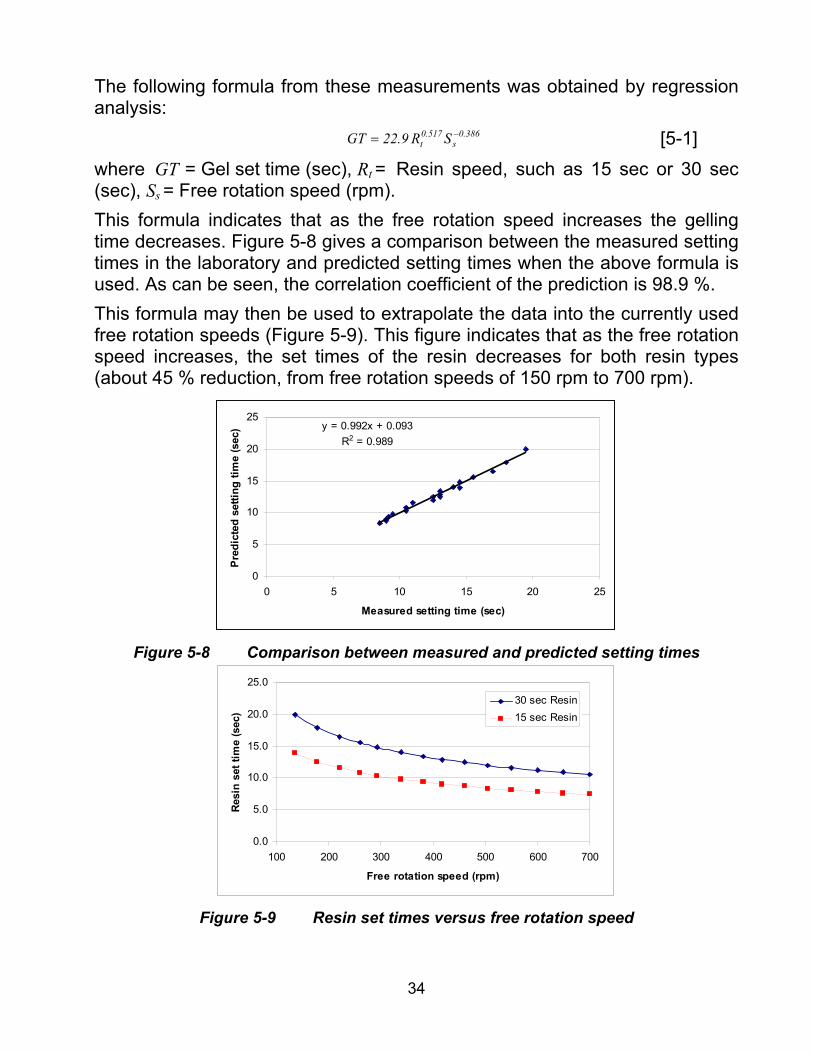
The following formula from these measurements was obtained by regression analysis:
386.0s
517.0t SR9.22GT −= [5-1]
where GT = Gel set time (sec), Rt = Resin speed, such as 15 sec or 30 sec (sec), Ss = Free rotation speed (rpm). This formula indicates that as the free rotation speed increases the gelling time decreases. Figure 5-8 gives a comparison between the measured setting times in the laboratory and predicted setting times when the above formula is used. As can be seen, the correlation coefficient of the prediction is 98.9 %. This formula may then be used to extrapolate the data into the currently used free rotation speeds (Figure 5-9). This figure indicates that as the free rotation speed increases, the set times of the resin decreases for both resin types (about 45 % reduction, from free rotation speeds of 150 rpm to 700 rpm).
y = 0.992x + 0.093R2 = 0.989
0
5
10
15
20
25
0 5 10 15 20 25
Measured setting time (sec)
Pre
dict
ed s
ettin
g tim
e (s
ec)
Figure 5-8 Comparison between measured and predicted setting times
0.0
5.0
10.0
15.0
20.0
25.0
100 200 300 400 500 600 700
Free rotation speed (rpm)
Resi
n se
t tim
e (s
ec)
30 sec Resin15 sec Resin
Figure 5-9 Resin set times versus free rotation speed

35
5.3 Resin quality control procedures Underground short encapsulated pull testing (SEPT) is a method which is frequently used to determine the performance of the support as part of a mine’s quality control procedures. These tests give a good indication of how the support performs in situ, but SEPTs are also time consuming to perform, and therefore expensive, making them impractical for the routine quality assurance testing of resin. Currently, the resin quality in South Africa is controlled by the “SABS-1534:2002” specification. It has been found, however, that resin which has passed the SABS specifications may still fail in underground SEPTs. For this reason, testing facilities were required and built by both Anglo Coal and Minova South Africa, with the aim of identifying faulty resin before being transported underground.
5.3.1 Performance testing of expired resin Defective resin can be caused by improper storage/transportation (too hot, too cold, too wet, or shelf life exceeded), or (rarely) manufacturing problems. Manufacturers indicate the expiry date, together with other information on each resin box. These dates are usually determined through laboratory tests at room temperatures in well-ventilated rooms. In comparison, the temperatures in an underground environment can vary substantially. Resin can therefore expire at a different time to that which is indicated on the box. In order to demonstrate this effect, a series of in situ SEPTs were conducted. In these tests, 30-second resin was used and all tests were conducted under near-identical conditions in a sandstone roof. Table 5-1 shows the expiry status of the resin used.
Table 5-1 Batch
Number Remarks Batch 1 Expired for 6 months Batch 2 Expired for 1 month Batch 3 Expired for 1 day Batch 4 Not Expired
Figure 5-10 indicates that expired resin may cause a reduction in support performance of up to 33 per cent.

36
0.00
0.10
0.20
0.30
0.40
0.50
0.60
0.70
Batch 1 Batch 2 Batch 3 Batch 4
Bon
d St
reng
th (k
N/m
m)
Not
exp
ired
Figure 5-10 Performance of expired resin
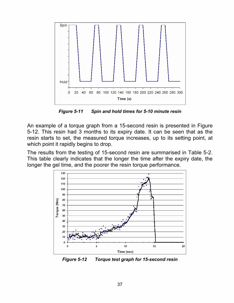
5.3.2 Torque testing of resin At Anglo Coal’s laboratory, tests were conducted on 13 different types of resins. The resins had different set times, namely 15-second spin to stall resin, 30-second, 60-second and 5-10-minute (all spin and hold resins) and also had different expiry dates. Each resin was spun until it stalled, except for the 5-10-minute resin. Due to its long setting time, the 5-10-minute resin was spun differently. It was spun for 10 seconds and then held for 30 seconds, repeatedly until the resin set – Figure 5-11.
37
Figure 5-11 Spin and hold times for 5-10 minute resin
An example of a torque graph from a 15-second resin is presented in Figure 5-12. This resin had 3 months to its expiry date. It can be seen that as the resin starts to set, the measured torque increases, up to its setting point, at which point it rapidly begins to drop. The results from the testing of 15-second resin are summarised in Table 5-2. This table clearly indicates that the longer the time after the expiry date, the longer the gel time, and the poorer the resin torque performance.
Figure 5-12 Torque test graph for 15-second resin

38
Table 5-2 15-second torque test results
Batch TorqueTime to
set Remarks A 120 14 Not expired B 81 16 Expired 1 month before C 60 18.5 Expired 3 months before
Similar results were found for 30-second, 60-second and 5-10 minute resins. This implies that a torque test could be a quick and easy method of detecting expired resin before it goes underground.
5.4 Effect of finger gloving on resin performance Finger gloving occurs when the Mylar cartridge wrapper remains intact around the hardened resin. This prevents the resin from completely bonding to the rock. There has been much debate upon whether this has a significantly negative affect on bond strength, grip factor and system stiffness. A series of laboratory tests were conducted to observe the extent of finger gloving in roofbolting. These tests also enabled the impact that the differing installation methods had on the extent of finger gloving to be observed. By cutting open the Perspex tubes, finger gloving could be further observed from an internal perspective. An example of this can be seen in Figure 5-13.
Figure 5-13 Example of resin capsule wrapped around bolt installation
Because these tests were performed in a laboratory environment, using Perspex tubes, it is accepted that underground conditions are not replicated exactly. A bolt hole underground will provide a rougher, more uneven hole than provided in these tests. Despite this, finger gloving is still likely to occur in an underground environment to some extent. Figure 5-14 demonstrates one of the major concerns associated with finger gloving. In this sample, the Mylar capsule has prevented the resin from bonding to the threaded walls of the installation tube. However, this problem has been exacerbated by the removal of the bolt from the test sample so that
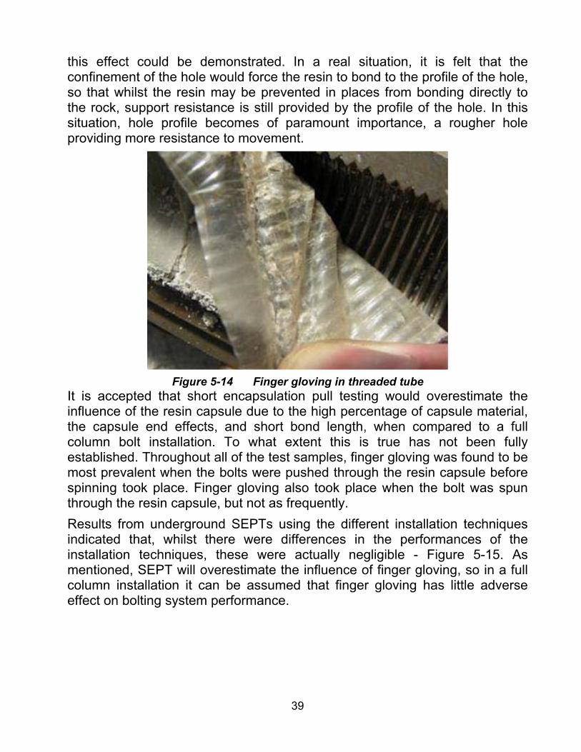
39
this effect could be demonstrated. In a real situation, it is felt that the confinement of the hole would force the resin to bond to the profile of the hole, so that whilst the resin may be prevented in places from bonding directly to the rock, support resistance is still provided by the profile of the hole. In this situation, hole profile becomes of paramount importance, a rougher hole providing more resistance to movement.
Figure 5-14 Finger gloving in threaded tube
It is accepted that short encapsulation pull testing would overestimate the influence of the resin capsule due to the high percentage of capsule material, the capsule end effects, and short bond length, when compared to a full column bolt installation. To what extent this is true has not been fully established. Throughout all of the test samples, finger gloving was found to be most prevalent when the bolts were pushed through the resin capsule before spinning took place. Finger gloving also took place when the bolt was spun through the resin capsule, but not as frequently. Results from underground SEPTs using the different installation techniques indicated that, whilst there were differences in the performances of the installation techniques, these were actually negligible - Figure 5-15. As mentioned, SEPT will overestimate the influence of finger gloving, so in a full column installation it can be assumed that finger gloving has little adverse effect on bolting system performance.
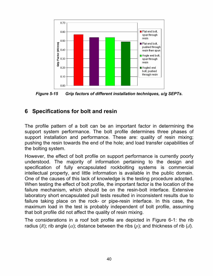
40
Figure 5-15 Grip factors of different installation techniques, u/g SEPTs.
6 Specifications for bolt and resin The profile pattern of a bolt can be an important factor in determining the support system performance. The bolt profile determines three phases of support installation and performance. These are: quality of resin mixing; pushing the resin towards the end of the hole; and load transfer capabilities of the bolting system. However, the effect of bolt profile on support performance is currently poorly understood. The majority of information pertaining to the design and specification of fully encapsulated rockbolting systems is commercial intellectual property, and little information is available in the public domain. One of the causes of this lack of knowledge is the testing procedure adopted. When testing the effect of bolt profile, the important factor is the location of the failure mechanism, which should be on the resin-bolt interface. Extensive laboratory short encapsulated pull tests resulted in inconsistent results due to failure taking place on the rock- or pipe-resin interface. In this case, the maximum load in the test is probably independent of bolt profile, assuming that bolt profile did not affect the quality of resin mixing. The considerations in a roof bolt profile are depicted in Figure 6-1: the rib radius (R); rib angle (α); distance between the ribs (p); and thickness of rib (d).
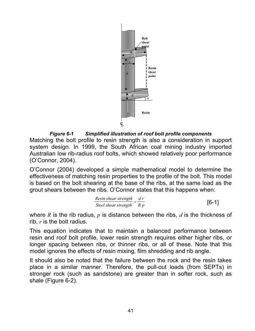
41
CL
r
p
d
Resin
R
Bolt shear point
Resin shear point
α
CL
r
p
d
Resin
R
Bolt shear point
Resin shear point
α
Figure 6-1 Simplified illustration of roof bolt profile components
Matching the bolt profile to resin strength is also a consideration in support system design. In 1999, the South African coal mining industry imported Australian low rib-radius roof bolts, which showed relatively poor performance (O’Connor, 2004). O’Connor (2004) developed a simple mathematical model to determine the effectiveness of matching resin properties to the profile of the bolt. This model is based on the bolt shearing at the base of the ribs, at the same load as the grout shears between the ribs. O’Connor states that this happens when:
pRrd
strengthshearSteelstrengthshearResin
= [6-1]
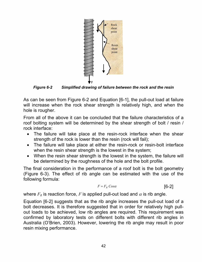
where R is the rib radius, p is distance between the ribs, d is the thickness of rib, r is the bolt radius. This equation indicates that to maintain a balanced performance between resin and roof bolt profile, lower resin strength requires either higher ribs, or longer spacing between ribs, or thinner ribs, or all of these. Note that this model ignores the effects of resin mixing, film shredding and rib angle. It should also be noted that the failure between the rock and the resin takes place in a similar manner. Therefore, the pull-out loads (from SEPTs) in stronger rock (such as sandstone) are greater than in softer rock, such as shale (Figure 6-2).
42
F
Rock shear point
Resin shear point
FF
Rock shear point
Resin shear point
Figure 6-2 Simplified drawing of failure between the rock and the resin
As can be seen from Figure 6-2 and Equation [6-1], the pull-out load at failure will increase when the rock shear strength is relatively high, and when the hole is rougher. From all of the above it can be concluded that the failure characteristics of a roof bolting system will be determined by the shear strength of bolt / resin / rock interface:
• The failure will take place at the resin-rock interface when the shear strength of the rock is lower than the resin (rock will fail);
• The failure will take place at either the resin-rock or resin-bolt interface when the resin shear strength is the lowest in the system;
• When the resin shear strength is the lowest in the system, the failure will be determined by the roughness of the hole and the bolt profile.
The final consideration in the performance of a roof bolt is the bolt geometry (Figure 6-3). The effect of rib angle can be estimated with the use of the following formula:
αCosFF R= [6-2]where FR is reaction force, F is applied pull-out load and α is rib angle. Equation [6-2] suggests that as the rib angle increases the pull-out load of a bolt decreases. It is therefore suggested that in order for relatively high pull-out loads to be achieved, low rib angles are required. This requirement was confirmed by laboratory tests on different bolts with different rib angles in Australia (O’Brien, 2003). However, lowering the rib angle may result in poor resin mixing performance.

43
F
Rib
FR
α
α
F
F
Rib
FR
α
α
F
Figure 6-3 Effect of rib angle on pull-out loads (simplified)
7 Effect of bit, annulus and rock type 7.1 Performance of bits Two types of drill bits are commonly used in South African collieries. These are the 2-prong bits and the spade bit. Both bits are shown in Figure 7-1.
Spade bit 2-Prong bitSpade bit 2-prong bit
Figure 7-1 Spade and 2-prong bits (25 mm)
A total of 40 short encapsulated pull tests were conducted in order that the performance of the two different bit types could be determined. The results from these tests in sandstone and shale are summarised in Figure 7-2. As can be seen in the figure, the 2-prong bit outperformed the spade bit in both rock types. However, the annuli obtained from the 2-prong bit were always greater than those from the spade bit (Figure 7-3). This is probably because of rougher holes obtained with 2-prong bits. The stiffnesses obtained from the 2-prong bits were also greater than those from the spade bit (Figure 7-4). These findings suggest that 2-prong bits are more effective in collieries than the spade bits.

44
0.0
0.1
0.2
0.3
0.4
0.5
0.6
0.7
Sandstone Shale
Bond
Stre
ngth
(kN/
mm
)
2-Prong BitSpade Bit
Figure 7-2 Performance of spade bit and 2-prong bit
2.5
2.6
2.7
2.8
2.9
3.0
3.1
3.2
3.3
3.4
Sandstone Shale
Hol
e A
nnul
us (m
m)
2-Prong BitSpade Bit
Figure 7-3 Hole annuli obtained from the 2-prong and spade bits
0.0
20.0
40.0
60.0
80.0
100.0
120.0
140.0
Sandstone Shale
Ove
rall
Stiff
ness
(kN/
mm
)
2-Prong BitSpade Bit
Figure 7-4 Overall stiffnesses obtained from the 2-prong and spade bits
7.2 Effect of hole annulus Borehole annulus is defined as half of the difference between the bolt and hole diameters. As a continuation to the investigation to determine the effect of borehole annulus on support performance, an additional 68 SEPTs were

45
conducted under near identical conditions in sandstone and shale roofs. These tests were done using a variety of different sized drill bits in order to obtain the necessary annuli. The results from these tests are shown in Figure 7-5, and it can be seen that an annulus between 2.5 mm and 3.8 mm resulted in the highest bond strengths. Another interesting point is that as the annulus drops below 2 mm, it appears to have a negative effect on the bond strength. This confirms the findings of tests conducted by Hagan (2003) in Australia.
0.00
0.10
0.20
0.30
0.40
0.50
0.60
0.70
0.0 1.0 2.0 3.0 4.0 5.0 6.0 7.0 8.0 9.0
Annulus (mm)
Bon
d S
tren
gth
(kN
/mm
)
ShaleSandstoneCoal
2.5 mm to 3.8 mm
Figure 7-5 Effect of hole annulus on bond strength
Note that the annuli in Figure 7-5 are determined from the actual hole and bolt diameter measurements, and not from the bit size. Generally, 24 mm or 25 mm bits with 20 mm roof bolts give an annulus of 2.8 mm and 4.5 mm respectively. It is therefore suggested that these bit sizes should be used with 20 mm roof bolts.
7.3 Effect of rock types As has been indicated previously by many researchers, rock type greatly affects support performance. To investigate this effect, a series of pull tests were conducted. Figure 7-6 highlights the very distinct differences between bolt system performances in different rock types. The results clearly show that sandstone produces significantly better results than shale and coal, as was explained in Section 6 of this report. From these results it can be concluded that rock type is one of the primary factors influencing support system performance.

46
0.00
0.10
0.20
0.30
0.40
0.50
0.60
0.70
Sandstone Shale Coal
Bon
d St
reng
th (k
N/m
m)
Figure 7-6 Effect of rock type on support performance
8 Roofbolt installation techniques Roofbolt installation is often a contentious issue, with a number of theories put forward as the correct method of installation. The main issues are whether to push the bolt to the back of the hole before spinning, or if the bolt should be spun through the resin whilst the bolt is pushed to the back of the hole. In a full column resin installation with a long bolt, the resistance of the resin can make it difficult to achieve pushing the bolt to the back of the hole. It was also shown in SIM 020205 that roofbolting machines are not always in the best condition and may not have the required thrust to push the bolt through the resin. In these situations the operator has little choice but to spin at least a portion of the bar through the resin capsule. However, an early start to spinning the resin in a long-bolt installation may result in an over mixing of resin. It is therefore important to determine optimal spinning and pushing of the bolt through the resin. Another issue which necessitates investigation, is the nature of the bolt end. Mines use either a flat ended bolt or an angled end bolt, usually at approximately 45 degrees. A flat ended bolt is suitable for installation of smaller, 0.9 m and 1.2 m, bolts. As the bolts become longer, it becomes more difficult to force the flat end bolt through the resin capsules required for a full column installation without spinning the bolt through a portion of the resin. The primary reason for using an angled end bolt is to assist in punching through the resin capsule and to shred the capsule’s film. A problem can however arise if the bolt hole is considerably larger than the bolt diameter.

47
This can lead to the resin capsule slipping to one side of the bolt, not puncturing the capsule, and leading to poor quality mixing of the resin and catalyst. Another concern is that of “finger-gloving”, where the bolt pierces the capsule from the bottom and becomes encased within the capsule. Mixing can occur but as the resin does not bond to the rock, in this situation, the load transfer characteristics are debatable. To determine the effects of different installation methods on the mixing capabilities of a point anchored resin bolt, a series of laboratory tests were conducted using transparent Perspex tubes. Four different methods of installation were tested, namely:
• Flat ended bolt, spun through the resin capsule;
• Flat ended bolt, pushed through the resin capsule then spun;
• Angle ended bolt, spun through the resin capsule;
• Angle ended bolt, pushed through the resin capsule then spun.
Visual observations were noted on the quality of the mixing for each method, before the Perspex tubes were split and removed to allow a more detailed inspection of the mixing process. The tubes were clear Perspex, 500 mm in length, 3 mm thickness, with an internal diameter of 30 mm. Short encapsulation pull tests (SEPT) were also performed underground in a sandstone roof to test the pullout resistance of each method.
8.1 Flat end bolt, spun through resin capsule Underground SEPTs determined that a flat ended bolt, spun through the resin capsule whilst being installed provided consistent grip factors of 0.6 kN/mm and the highest average stiffness of any of the tests. Visual observations of three test samples indicated that this method provides the most consistent mixing of the four methods used. Whilst the top 50 mm of the Perspex tube appears to have a marble effect, indicating that resin and catalyst have not mixed correctly, the remaining length of tube shows a consistent grey colouring. This implies that adequate mixing has taken place, Figure 8-1.

48
Figure 8-1 External observations of flat ended bolt, spun through the resin
capsule
8.2 Flat end bolt, pushed through resin then spun A flat end bolt pushed through the resin to the back of the hole before spinning is shown in Figure 8-2. In this case the resin can be seen pushed to the back of the hole and appears to be poorly mixed with catalyst. At the bottom of the mix, the catalyst can be clearly seen, unmixed with resin. This is due to the catalyst being less viscous than the resin before mixing takes place. As the bolt is pushed through the resin capsule, both resin and catalyst are displaced. The catalyst, being of lower viscosity, is pushed to the bottom of the hole leaving only a section of approximately 100 mm in the middle providing adequate mixing of the resin.
Figure 8-2 Flat end bolt, pushed through resin then spun
8.3 Angle end bolt spun through resin An angle ended bolt which is spun through the resin capsule should provide a similar mix to that of a flat ended bolt. The theory of the angled bolt is that it will tear and shred the Mylar capsule more easily than a flat ended bolt. Figure 8-3 shows the mixing achieved in this case. As can be seen, the mixing appears to show resin at the top of the tube, followed by approximately 150 mm of well mixed resin and catalyst and a small portion (approximately 20 mm) of relatively unmixed catalyst at the bottom portion of the test tube.

49
Figure 8-3 Angle end bolt spun through resin
8.4 Angle end bolt pushed through resin then spun Angle end bolts pushed through the resin capsule and then spun exhibit similar characteristics to the flat end bolts when installed in the same way. As with the flat end bolt, the difference in viscosity between the catalyst and resin causes a displacement of the catalyst when a bolt is forced through the resin capsule. This again lead to an imperfect mix between resin and catalyst.
8.5 Quantification of the effects of installation method In order to quantify the effects of the different installation methods identified, a series of underground short encapsulation pull tests were carried out in near identical conditions in a sandstone roof. Tests were performed using both 15 second spin-to stall resin, and 30 second spin and hold resin. For each set of tests a total of 5 tests were conducted and the best of three results were used in the analysis. The results of the tests can be seen in Figure 8-4 and Figure 8-5.

50
0.00
0.10
0.20
0.30
0.40
0.50
0.60
0.70
Gri
p Fa
ctor
(kN/
mm
) Flat end bolt, spun throughresinFlat end bolt, pushed throughresin then spunAngle end bolt, spun throughresinAngled end bolt, pushedthrough resin
Figure 8-4 Grip factors for 30 second resin in a sandstone roof
0.00
0.10
0.20
0.30
0.40
0.50
0.60
0.70
Grip
Fac
tor
(kN
/mm
) Flat end bolt, spun throughresinFlat end bolt, pushed throughresin then spunAngle end bolt, spun throughresinAngled end bolt, pushedthrough resin
Figure 8-5 Grip factors for 15 second resin in a sandstone roof
These figures highlight that the differences in grip factors obtained from the different installation techniques are minimal. However, the angle bolt which was pushed through the resin before spinning gave consistently poorer grip factors for both resin types. This installation method showed an 8 per cent drop in performance for 30 second resin, and an 18 per cent drop for 15 second resin. A comparison of the stiffnesses achieved in the tests was also conducted. Figure 8-6 shows the system stiffness for the various installation methods with a 30 second resin. It can be seen that the tests involving flat ended bolts

51
provided a much stiffer system than angled bolts. Flat ended bolts which were spun through the resin capsule provided a stiffness of more than double that of the flat ended bolts which were pushed to the back of the hole before spinning. Angled bolts provided the poorest stiffness for 30 second resins, with both installation methods less than 20 per cent of the stiffness of the flat bolt, spun through.
0
50
100
150
200
250
300
350
400
450
500
Stif
fnes
s (k
N/m
m)
Flat end bolt, spun throughresin
Flat end bolt, pushed throughresin then spun
Angle end bolt, spun throughresin
Angled end bolt, pushedthrough resin
Figure 8-6 Stiffness of 30 second resin in a sandstone roof
The 15 second resin showed a similar trend in terms of stiffness performance (Figure 8-7). The flat ended bolts outperform the angled bolts in both sets of tests. Although more closely matched than the 30 second resin, the flat ended bolt spun through the resin capsule again gave the best stiffness, closely followed by flat end bolts pushed through the resin, then spun.
0
20
40
60
80
100
120
140
160
Stif
fnes
s (k
N/m
m)
Flat end bolt, spun throughresinFlat end bolt, pushed throughresin then spunAngle end bolt, spun throughresinAngled end bolt, pushedthrough resin
Figure 8-7 Stiffness of 15 second resin in a sandstone roof

52
It should be noted that although large variations in the stiffnesses of each system was observed, they were all within the acceptable limits of a 20 mm roof bolting system (60 kN/mm, see SIM 020205 final project report for details), except the angled bolt pushed through the resin. It is therefore recommended that using an angled bolt and pushing through the resin capsule should be eliminated as an installation method as much as possible to obtain the maximum support performance.
9 Support system selection and design For a long period of time, the design of roof support systems in South Africa was based purely on experience and judgment by mining personnel. Although this approach was fairly successful and improvements in roof bolt design have been made over the last decade, a more scientific approach based on sound engineering principles is desirable. When an underground opening consists of a laminated immediate roof underlying a strong, self-supporting layer, the ‘suspension’ support mechanism can be used. However, when the roof (within a practically boltable horizon) consists of a succession of thin beams, none of which are self-supporting, the suspension principle cannot be applied. In this case, it is necessary to combine individual beams to provide a composite beam that is self-supporting in the ‘beam-building’ support mechanism. In order to accomplish this, the bolts must be designed so as to prevent shearing between individual layers of the composite beam. A methodology for this is developed in the following sections.
9.1 Determination of roof behaviour and failure mechanism
9.1.1 Roof behaviour Before an opening is excavated, the virgin stress distribution is relatively uniform and the magnitude of vertical stress increases proportionally to the depth. But once an opening is made, the portion of the strata directly above the opening loses its original support and the stress equilibrium is disturbed. The roof starts to sag under the gravitational force. If the immediate roof strata are competent, the sag will stop before the roof collapses and the stresses around the opening will eventually reach a new equilibrium. However, in coal mines, the immediate roofs of roadways are not always competent enough to sustain the changes of the stress distribution and the interaction induced by mining. These may finally collapse into the opening if they are not sufficiently supported by some means (Peng, 1986).

53
To maintain the stability of an underground opening, it is essential to keep the immediate roof-softening zone stable, Figure 9-1. Roof bolts in this zone, force all the bolted layers to sag with the same magnitude; the layers within the bolting range thus act like a solid beam. Building such a beam is actually the ultimate goal of roof bolting where beam building is the required prevalent mechanism.
Pillar Pillar
Bolted zoneMeasured to be maximum2.5 m
Active roof softening zone
Pillar Pillar
Bolted zoneMeasured to be maximum2.5 m
Active roof softening zone
Figure 9-1 Zone of roof softening
An analysis was conducted on roof-softening measurements collected from a total of 54 intersection and roadway sites at depths of 32 m to 170 m, situated in significantly different geotechnical environments. The maximum heights of bed-separations in these sites were measured prior to bolting, Figure 9-2. The results showed that the maximum roof-softening height is 2.5 m in South African collieries. This indicates that there is no evidence of a substantial increase in the height of potentially unstable roof strata, as is the case in some overseas coal mines, Figure 9-3.
0.0
0.5
1.0
1.5
2.0
2.5
3.0
Sta
ble
roof
ele
vatio
ns (m
)
RoadwaysIntersections
Figure 9-2 Measured height of roof-softening in intersections and roadways in
South African collieries
54
Figure 9-3 An example of roof-softening in a coal mine in the USA (courtesy of
Dr. C. Mark) The average height of roof-softening is 1.07 m, which is less than the roof bolt lengths commonly used in South Africa. This indicates that most supported roofs should be stable in South Africa, if adequate support is installed properly. These findings coincide well with investigations conducted on falls of ground fatalities for the period 1970 to 2003. Vervoort (1990) investigated the falls of ground fatalities in South African collieries for the period 1970-1988, and this has since been updated to cover the period 1989 to 2003. Figure 9-4 compares the two data sets with respect to thickness of fall. This Figure indicates that a large proportion of fall of ground accidents involved relatively small thicknesses. However, the proportion of larger falls of ground has increased slightly in the recent data.
0
10
20
30
40
50
60
70
80
90
0.0 - 0.5 0.5 - 1.0 1.0 - 1.5 1.5 - 2.0 2.0 - 2.5 2.5 - 3.0
THICKNESS (m)
PER
CEN
TAG
E O
F FO
G Vervoort (1990)
New Data (1989 -2003)
Figure 9-4 The thickness of FOGs causing fatalities for the period 1970 – 1995
The cumulative distribution of thicknesses which caused FOG fatalities during the period 1989 to 2003, and the roof softening heights measured

55
underground, are shown in Figure 9-5. As can be seen, 95 % of all instabilities had a thickness of less than 2.2 m. Moreover, 70 % of all serious FOGs had a thickness of 0.5 m or less.
0.0%
10.0%
20.0%
30.0%
40.0%
50.0%
60.0%
70.0%
80.0%
90.0%
100.0%
0 0.5 1 1.5 2 2.5 3
Height of roof-softening (m)
Cum
ulat
ive
Freq
uenc
ySonic ProbeFOG Fatalities
2.2 m
Figure 9-5 Cumulative distribution of FOG thicknesses and the height of roof
softening measured underground Figure 9-6 records measured deformations for the same set of intersections and roadways depicted in Figure 9-2. In interpreting these results, it is instructive to recall that according to standard beam theory, the deflection at the centre of a beam increases as the fourth power of the span L. The average deformations in Figure 9-6 are consistent with this, in that the span of an intersection is about √2 times the roadway span, and (√2)4 = 4 ≈ 5.28/1.31 (see Figure 9-6). Thus, there is some justification for treating the exposed roof as a simple beam, as is done in the following sections.
0
1
2
3
4
56
7
8
9
10
11
12
Roo
f def
orm
atio
n (m
m)
RoadwayIntersection
Intersection average (5.28 mm)
Roadway average (1.31 mm)
Figure 9-6 Measured deformations in intersections and roadways. The average
deformations are in the ratio 5.28/1.31 = 4.03.

56
9.1.2 Strata tensile strength estimation Before a roof bolt system is designed for a certain mechanism, it is important to establish the geology for at least 2.5 m into the roof, which will determine the support mechanism to be used. If the immediate roof is very weak, but a competent layer exits higher in the roof, the suspension support mechanism is indicated. However, when the entire roof consists of a succession of thin beams, none of which are self-supporting, the suspension principle cannot be applied. It is therefore suggested that before any decision has been made on any support system, a detailed geotechnical investigation should be conducted. This investigation can be carried out using impact splitting tests (IST), RQD or RMR. For practical purposes, impact splitting tests are advocated to determine the rock qualities of the first 2.5 m into the roof, and thus the support mechanism. A testing programme was initiated to determine the tensile strength of competent layers using IST at a colliery. Four boreholes were drilled and cored in very close proximity (less than 10 m). A series of samples at exactly the same depths were collected from all four borehole cores. While two sets were tested in the laboratory using Brazilian Tensile Strength (BTS) tests, the other two were tested using impact splitting tests (IST). A total of 62 (31 BTS and 31 IST) tests were conducted in competent sandstone and coal samples. Figure 9-7 shows the relationship between the Impact Split Rating (ISR) and Brazilian Tensile Strength (BTS) tests. As can be seen there is a relatively good correlation between these measures of rock quality (R2=0.91).
BTS = 0.46*ISR - 6.2R2 = 0.91
0
2
4
6
8
10
12
0 5 10 15 20 25 30 35 40
Unit Rating (ISR)
BTS
(MPa
)
Figure 9-7 Relationship between the ISR and BTS

57
It is suggested that the following formula should be used in estimating the tensile strength of layers within the range of ISR and BTS used in this study. Note that jointing in the rock mass is not taken into account in this formula; therefore, a minimum safety factor of 1.5-2.0 is recommended in further calculations.
2.6*46.0 −= ISRBTS [9-1]
where ISR is impact splitting unit rating, and BTS is Brazilian Tensile Strength in MPa.
9.1.3 Required minimum competent layer thickness (suspension mechanism)
In the suspension mechanism, the lower (loose) layer is suspended from the upper (competent) layer using roof bolts (van der Merwe and Madden, 2002). This creates a surcharge load and increases the maximum tensile stress in the upper layer, above the abutments. This surcharged tensile stress (max)xxσ (MPa) can be calculated using the following formula:
2
2
(max) 2)(
com
lamcomxx t
LttgSF
+=
ρσ [9-2]
where SF=safety factor (1.5 - 2.0), ρg=specific weight of suspended strata (e.g. 0.025 MPa/m), L =span (bord width or intersectional diagonal width) (m), tcom=competent layer thickness (m), tlam=laminated lower strata thickness (m). For failure not to take place, the tensile strength of the competent layer should be greater than the tensile stress generated in this layer due to the total load. This simple approach is conservative, in that any virgin horizontal stresses that may exist are ignored. For a given mining geometry and tensile strength of material, the applicability of a suspension support mechanism can be determined using Equation [9-2]. If the calculated load results in a tensile stress greater than the capacity of the competent strata, beam building is recommended. If it does not exceed the tensile strength, then the strata will be stable and the suspension mechanism may be used.

58
9.2 Roof bolting mechanisms
9.2.1 Suspension mechanism The suspension mechanism is the most easily understood roof bolting mechanism. While the majority of roof bolts used are resin point anchors, mechanical anchors are also used (2 % only, Henson, 2005). The design of roof bolt systems based on the suspension principle has to satisfy the following requirements:
• The strength of the roof bolts has to be greater than the relative weight of the loose roof layer that has to be carried.
• The anchorage forces of the roof bolts have to be greater than the weight of the loose roof layer.
• Usually the support design is based on a safety factor, SF, chosen depending on the strata conditions, the importance of the roadway and uncertainties. A value of 1.5 to 2.0 is recommended by Wagner, 1985.
The number n of bolts/m2 required to support a loose layer or layers of thickness, tlam, is given by:
f
lam
Pgt
SFnρ
= [9-3]
where SF=safety factor, ρg=specific weight of suspended strata (e.g. 0.025 MPa/m), Pf =yield strength of bolt (MN). The area A that may be supported by one bolt is the inverse of n:
n1A = [9-4]
The required uniform bolt spacing, Lb, may then be determined from:
n1ALb == [9-5]
The necessary anchor length may be determined by a number of short encapsulated tests to determine the shear resistance τ (MPa) of the resin/rock interface:
rDlP
πτ = [9-6]
where P=load at which the system fails (N), D=hole diameter (mm), lr =length of the resin/rock bond in the hole (mm). In an actual bolting application, the required bond length lb is then:

59
22
2
dDLl c
b −=
δ [9-7]
where δ=capsule diameter, D=hole diameter, d =tendon diameter, Lc=capsule length. The shear resistance of the bolt has then to be checked: fb PDl ≥τπ [9-8]
Alternatively, a simpler way to determine required bond length lb , which also matches bond strength to tensile strength Pf of the bolts, is to take
sfb B/Pl ≥ [9-9]where Bs is the SEPT-measured bond strength (kN/mm). The required bolt length LB is then:
lambB tlL +≥ [9-10]where tlam is laminated lower strata thickness (m). The bolt length LB finally chosen should be such as to ensure the full bond length lb is comfortably inside the competent layer.
9.2.2 Beam building mechanism Classical beam theory was first used by Obert and Duvall (1967) in the design of roof bolt patterns. The derivations in this section also used standard beam theory (e.g. Popov 1978), but took into account an assumed parabolic roof-softening profile of loading, Figure 9-1 and Figure 9-8 below.
Figure 9-8 Built-beam with parabolic loading, total height h1. Max. horiz. tensile
stress occurs at A, max inter-bed shear stress at B.
The first consideration in the design of the beam building mechanism is to determine the minimum required thickness h of the built-beam which will be stable from the tensile failure point of view. The maximum tensile stress must be smaller than the tensile strength of the upper layer of the built beam with an appropriate safety factor. The maximum allowable tensile stress (at point A in Figure 9-8) in a built-beam with a parabolic surcharge load evaluates to:
C
Roadway/Intersection
Built-beam
h1
h
L
AB

60
21
2
xx hhgL
52SF
2L ρ
σ =
± [9-11]
where SF is safety factor (1.5-2.0), ρg is the specific weight of the strata (typically 0.025 MPa/m), L is the span of the roadway or intersection, h is the built-beam thickness (bolt length), and h1 is the total height of roof softening at the site. The tensile stress in the lower surface at mid-span of the built-beam (point C in Figure 9-8) is only about one-half of this value and need not be checked out further. An illustration of the use of Equation [9-11] is presented in Table 9-1, which assumes SF = 1.5, ρg = 0.025 MPa/m, L = 6 m. As can be seen, a standard bolt length of 1.2 m is able to create a sufficiently strong built-beam in even the weakest roof with maximal roof-softening height (i.e. 2.5 m, Figure 9-1). It should be born in mind, however, that for intersections, the values in Table 9-1 will halve because of the greater span L involved.
Table 9-1 Beam-building: maximum allowable roof-softening heights h1 for standard bolt lengths h, coal or other weak roof strata.
Bolt length h (m)
Coal h1, ISR=16 (BTS=1.16 MPa)
Shale h1, ISR=20 (BTS=3.0 MPa)
0.6 0.77 2.00 0.9 1.74 4.50 1.2 3.09 8.00
The maximum inter-bed shear stress in the built-beam (point B in Figure 9-8) is given by:
h2Lgh1
maxρ
τ = [9-12]
For the built composite beam to act as a single entity, the shear stress given by Equation [9-12] has to be overcome by the action of the bolts. Two types of resistance are provided: frictional due to bolt pre-tensioning, and intrinsic shear strength of the bolts. Neglecting inter-layer cohesion, the frictional shear resistance of tensioned roof bolts can be calculated using the following formula (Wagner, 1985):
µpR nFT = [9-13]where n is number of bolts per square meter, Fp is pre-tension of the bolt (usually 50 kN), and µ is the coefficient of friction between the layers.

61
Borehole samples from 5 collieries were obtained with the purpose of determining the coefficient of friction between various rock types (coal, sandstone, shale, calcite etc) using shear box tests. The results showed only a narrow spread (± 10 %), and the average value µ = 0.46 can be used in the design of colliery roof support systems. The shear strength of the bolts also generates considerable shear resistance, which must be considered in the design. This can be calculated using the following formula:
RB nST = [9-14]where SR is the shear strength of a bolt (in kN). This is most readily expressed as a fraction of the ultimate tensile strength (UTS) of the bolt, and estimates ranging up to 90 % have been determined experimentally by workers including Azuar (1977) and Roberts (1995). It is here suggested that the shear strength of a full column bolt is taken to be equal to 80 % of the UTS Sb of the bolt (based on 600 MPa for standard roof bolts in S. African collieries, e.g. 190 kN for 20 mm bolts). The total shear resistance of bolting (kN/m2) can thus be expressed as:
)S8.0F46.0(nT BpTOTAL += [9-15]where n is the bolt density (bolts/m2), Fp is the pre-tension on the bolt (usually 50 kN), and SB is the UTS of the bolt (190 kN for a 20 mm bolt). This value, with an appropriate safety factor, has to exceed the value given by Equation [9-12]. The effect of surcharge load created by the soft strata resting on bolted strata for different bolt lengths is shown in Figure 9-9 (bord width is 6.0 m) using Equation [9-12]. This figure indicates that the maximum shear stress in the bolted strata increases significantly as the thickness of surcharge strata h1 increases from 1.0 m to 2.5 m. The figure also shows that as the thickness of bolted strata h increases, the shear stress decreases in the beam. The implication of increasing thickness of soft strata on the bolted roof is that the required support density will also increase, and eventually will reach a point where the roof will not be able to be supported, Figure 9-10.

62
0.00
0.05
0.10
0.15
0.20
0.25
0.0 0.5 1.0 1.5 2.0 2.5 3.0
Roof-softening thickness (m)
Shea
r str
ess
(MPa
)
0.9 m bolt
1.2 m bolt1.5 m bolt
Figure 9-9 Effect of thickness of soft strata on shear stress in a beam (bord
width is 6.0 m)
0.0
0.2
0.4
0.6
0.8
1.0
1.2
0.5 1.0 1.5 2.0 2.5 3.0
Roof-softening thickness (m)
Req
uire
d su
ppor
t den
sity
(1/m
2 ) 0.9 m bolt1.2 m bolt
1.5 m bolt
Figure 9-10 Effect of increasing thickness of soft strata on required support
density (bord width is 6.0 m) Another important consideration in the beam building mechanism occurs when the roof softening height is within the bolted horizon. This usually occurs when the bolts are installed late, and separation has already taken place and destroyed the cohesion between the layers.

63
Pillar PillarPillar Pillar
Figure 9-8 Bed separation within the bolted horizon In this case, the safety factor of pull-out resistance (SFPR) of the bolting system should be calculated using the bond strength (Bs) between the resin, rock and the bolt using the following formula:
caps
sPR lkB
gtdLSF
ρ= [9-10]
where d=distance between the rows of roof bolts (m), L=span (m), ts=thickness of separated layer (m), k=number of bolts in a row, lcap=capsulation length (bolt length – ts) (m), ρg=specific weight of strata (MPa/m). Bond strength (grip factor) is measured through short encapsulation pull tests (SEPT). In order to measure the bond strength, it is necessary to shear the bond on the bolt-resin or resin-rock interface. With the modern high-strength, high-stiffness, polyester resins, it has been found that a bond length of 250 mm is appropriate for determining the bond strength. Bond strength (BS) is defined as:
)()(
mmLengthionEncapsulatkNAchievedLoadMaximumBS = [9-11]
While resistance to sliding is important in the case of bed separation within the bolted horizon, the load on the bolts (Lbolt)) should also be determined to avoid tensile failure of the bolts. The following formula can be used to calculate the load acting on the bolt when separation takes place:
kgtdL
L sbolt
ρ= [9-12]
where d=distance between the rows of roof bolts (m), L=span (m), ts=thickness of separated layer (m), k=number of bolts in a row, ρg=specific weight of strata (MPa/m).

64
9.3 Determination of stability of the immediate layer between the roof bolts
In the case of thin roof beds the spacing between bolts is critical. Wagner (1985) suggested that the distance between the bolts should not exceed a value of 10 times the thickness of the layer. However, to prevent the failure of the immediate roof between the bolts, the tensile stress between the bolts for the immediate layer may be calculated by assuming that the bolts create a fixed beam between them. If the tensile stress between the bolts exceeds the tensile strength of the material then the distance between the bolts should be reduced or an areal coverage system should be used. The maximum tensile stress may be calculated again from the clamped beam equation (van der Merwe and Madden, 2002):
2
2
(max) 2imm
tgtL
SF bxx
ρσ = [9-13]
where SF=safety factor (1.5 - 2.0), ρg=specific weight of immediate layer (MPa/m), Lb=distance between the bolts (m), timm=thickness of immediate layer (m). Note that in the case of low modulus layers overlaying the immediate layer, surcharge loading should be taken into account by suitably increasing t in the numerator of Equation [9-13]. These design approaches are based on the tensile strength of the material. Impact splitting tests can be used in determining the tensile strength of the immediate layer and thus the maximum allowable spacing between the bolts. However, laboratory testing is recommended to more accurately determine the tensile strength of the various coal strata materials and partings.
9.4 Further considerations Once these calculations are made, the roof support can be designed for suspension or beam building. However, these are not the only considerations required for ensuring a safe and stable mine roof. The quality of the support installation also plays a very important role in stability. As an extreme illustration to this, a series of roof bolt pull tests was conducted at a single colliery, on over 200 bolts, where mechanical anchors were used in the suspension mode. The bolts were intended to be able to sustain 5.0 tonnes of pre-tension. The results are shown in Figure 9-9. As can be seen, 80 (37 per cent) of the bolts did not develop any load, 190 (89 per cent) of them slipped after application of 2.0 tonnes pull-out load and none of them reached the prescribed 5.0 tonne load. This highlights the importance of selecting a
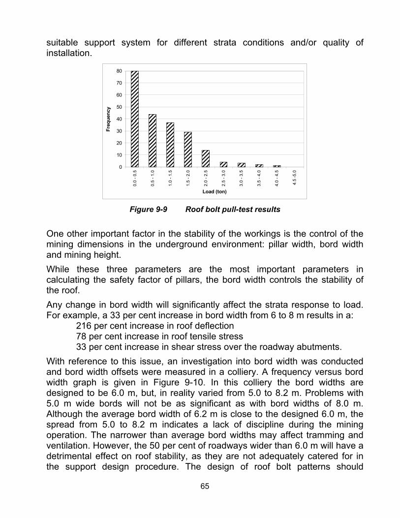
65
suitable support system for different strata conditions and/or quality of installation.
0
10
20
30
40
50
60
70
80
0.0
- 0.5
0.5
- 1.0
1.0
- 1.5
1.5
- 2.0
2.0
- 2.5
2.5
- 3.0
3.0
- 3.5
3.5
- 4.0
4.0
- 4.5
4.5
-5.0
Load (ton)
Freq
uenc
y
Figure 9-9 Roof bolt pull-test results
One other important factor in the stability of the workings is the control of the mining dimensions in the underground environment: pillar width, bord width and mining height. While these three parameters are the most important parameters in calculating the safety factor of pillars, the bord width controls the stability of the roof. Any change in bord width will significantly affect the strata response to load. For example, a 33 per cent increase in bord width from 6 to 8 m results in a: 216 per cent increase in roof deflection 78 per cent increase in roof tensile stress 33 per cent increase in shear stress over the roadway abutments. With reference to this issue, an investigation into bord width was conducted and bord width offsets were measured in a colliery. A frequency versus bord width graph is given in Figure 9-10. In this colliery the bord widths are designed to be 6.0 m, but, in reality varied from 5.0 to 8.2 m. Problems with 5.0 m wide bords will not be as significant as with bord widths of 8.0 m. Although the average bord width of 6.2 m is close to the designed 6.0 m, the spread from 5.0 to 8.2 m indicates a lack of discipline during the mining operation. The narrower than average bord widths may affect tramming and ventilation. However, the 50 per cent of roadways wider than 6.0 m will have a detrimental effect on roof stability, as they are not adequately catered for in the support design procedure. The design of roof bolt patterns should

66
therefore cater for these inadvertent increases in the bord widths, otherwise the corresponding increased probability of roof falls has major safety implications. These results highlight the importance of quality of installation and selection of the correct support system for the strata as well as control of the dimensions. If the installation or geometry control is poor or incorrect, no matter how good the design, the probability of roof falls will increase, creating a less safe environment.
0
2
4
6
8
10
12
14
16
184.
8
5.0
5.2
5.4
5.6
5.8
6.0
6.2
6.4
6.6
6.8
7.0
7.2
7.4
7.6
7.8
8.0
8.2
Bord width (m)
Freq
uenc
y
Figure 9-10 Bord width versus frequency measured underground
9.5 Support design methodology Using the material from above and the previous SIMRAC projects, the following flow chart has been developed, Figure 9-11, as an aid in designing the most appropriate roof bolting systems in different geotechnical environments in South African collieries. This design methodology compromises two main sections, namely, design in greenfield and design in existing operations. The important consideration in this design chart is to conduct detailed geotechnical investigations in both environments. Once these investigations have been completed, the design mechanism (suspension or beam building) can be determined. It is suggested that the design should also be evaluated financially. If the system is financially viable, it can then be implemented. However, the system should continuously be monitored and appropriate quality control procedures should be implemented for a successful support system.
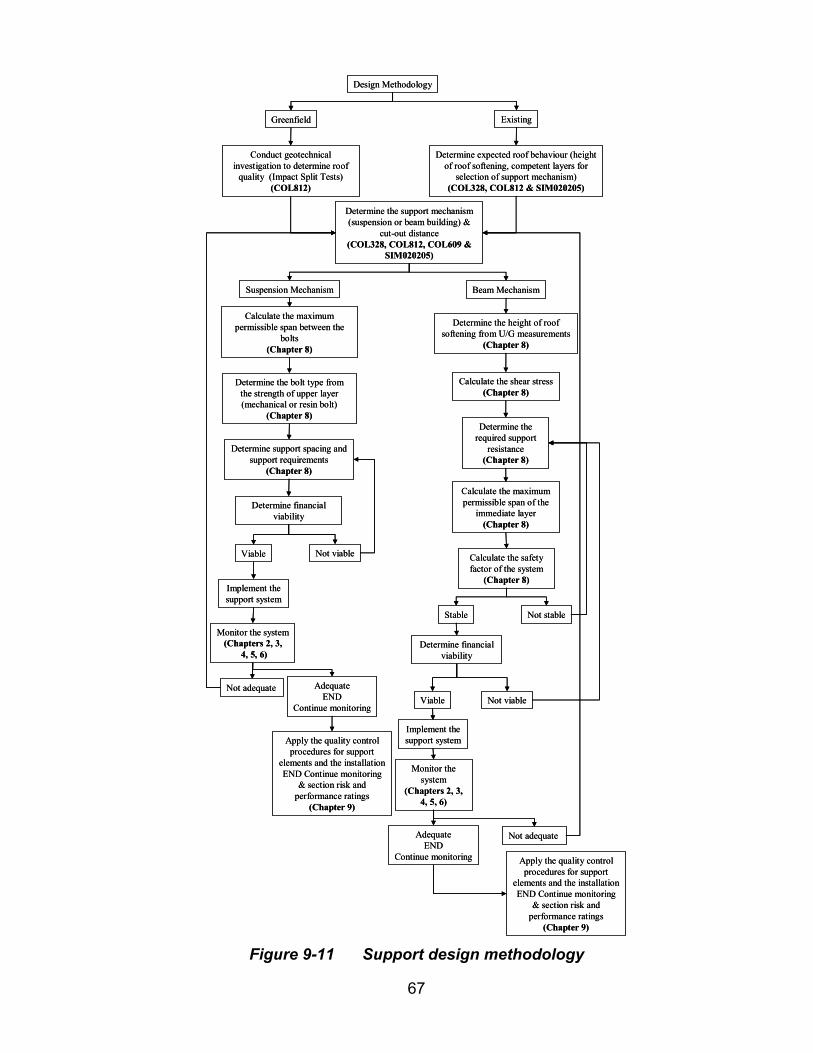
67
Design Methodology
Greenfield Existing
Conduct geotechnical investigation to determine roof
quality (Impact Split Tests)(COL812)
Determine the support mechanism (suspension or beam building) &
cut-out distance(COL328, COL812, COL609 &
SIM020205)
Determine expected roof behaviour (height of roof softening, competent layers for
selection of support mechanism)(COL328, COL812 & SIM020205)
Suspension Mechanism
Calculate the maximum permissible span between the
bolts(Chapter 8)
Determine the bolt type from the strength of upper layer (mechanical or resin bolt)
(Chapter 8)
Determine support spacing and support requirements
(Chapter 8)
Determine financial viability
Viable Not viable
Implement the support system
Monitor the system(Chapters 2, 3,
4, 5, 6)
Not adequate AdequateEND
Continue monitoring
Apply the quality control procedures for support
elements and the installationEND Continue monitoring
& section risk and performance ratings
(Chapter 9)
Beam Mechanism
Determine the height of roof softening from U/G measurements
(Chapter 8)
Calculate the shear stress(Chapter 8)
Determine the required support
resistance(Chapter 8)
Calculate the maximum permissible span of the
immediate layer(Chapter 8)
Calculate the safety factor of the system
(Chapter 8)
Stable Not stable
Determine financial viability
Viable Not viable
Implement the support system
Monitor the system
(Chapters 2, 3, 4, 5, 6)
Not adequate AdequateEND
Continue monitoring Apply the quality control procedures for support
elements and the installationEND Continue monitoring
& section risk and performance ratings
(Chapter 9)
Design Methodology
Greenfield Existing
Conduct geotechnical investigation to determine roof
quality (Impact Split Tests)(COL812)
Determine the support mechanism (suspension or beam building) &
cut-out distance(COL328, COL812, COL609 &
SIM020205)
Determine expected roof behaviour (height of roof softening, competent layers for
selection of support mechanism)(COL328, COL812 & SIM020205)
Suspension Mechanism
Calculate the maximum permissible span between the
bolts(Chapter 8)
Determine the bolt type from the strength of upper layer (mechanical or resin bolt)
(Chapter 8)
Determine support spacing and support requirements
(Chapter 8)
Determine financial viability
Viable Not viable
Implement the support system
Monitor the system(Chapters 2, 3,
4, 5, 6)
Not adequate AdequateEND
Continue monitoring
Apply the quality control procedures for support
elements and the installationEND Continue monitoring
& section risk and performance ratings
(Chapter 9)
Beam Mechanism
Determine the height of roof softening from U/G measurements
(Chapter 8)
Calculate the shear stress(Chapter 8)
Determine the required support
resistance(Chapter 8)
Calculate the maximum permissible span of the
immediate layer(Chapter 8)
Calculate the safety factor of the system
(Chapter 8)
Stable Not stable
Determine financial viability
Viable Not viable
Implement the support system
Monitor the system
(Chapters 2, 3, 4, 5, 6)
Not adequate AdequateEND
Continue monitoring Apply the quality control procedures for support
elements and the installationEND Continue monitoring
& section risk and performance ratings
(Chapter 9) Figure 9-11 Support design methodology
68
9.6 Conclusions It has been shown that for a successful support system design, detailed geotechnical investigations are required. The new design charts for the suspension support method highlight the importance of the thickness of the competent strata. These charts can be used to determine the appropriate design mechanism, which will assist rock engineers to create a safer and more stable environment. Distance between the bolts is also an important factor. The tensile stress in the immediate roof layer between the bolts should be calculated and compared against the material’s tensile strength to determine the stability of the exposed roof between the roof bolts. A simple methodology using impact splitting tests has been introduced to determine the tensile strength of roof materials. These tests can either be conducted during the planning stage or in an active mining stage in the design of roof support systems. Analyses of underground measurements highlighted that for a 40 per cent increase in the span, taken across the diagonal of an intersection, relative to the roadway span, the magnitude of the displacement in the roof increased by a factor of four. The results also showed no evidence of a substantial increase in the height of the bed separated, potentially unstable roof strata, as is the case in the high horizontal stress driven beam buckling mechanism experienced in overseas coal mines. Therefore, it was concluded that, in South African collieries, the magnitude of horizontal stresses is relatively low compared to overseas collieries. A detailed analysis of underground monitoring data also revealed that there is a good correlation between the underground measurements and simple beam theory. Underground measurement data showed that the maximum height of roof-softening measured in 54 sites in South African collieries is 2.5 m, which correlates well with the fall of ground data collected over 30 years in South Africa. The average height of roof-softening measured in these sites was 1.07 m, which is less than the roof bolt lengths commonly used in South Africa. The new design methodology and above results indicated that on average almost all supported roofs should be stable in South Africa, if adequate support is installed properly. A number of borehole samples from 5 collieries were obtained with the purpose of determining the coefficient of friction between the various rock types using shear box tests. The subject of coefficient of friction between the roof layers in the beam building mechanism has been investigated and an average value of 0.46 is recommended in the design of roof bolting systems.

69
It is recommended that an extensive study into the shear strength of full column resin bolts is required. The importance of controlling the bord widths to match their design dimensions needs to be brought to the attention of the mining industry as a whole. The quality of the installation of the individual roof support elements is as important as the overall roof support design. The installation and support performance should be monitored using suitable extensometers or tell tales. With the suspension based support system, the load carrying capacity of individual bolts is directly related to the areal coverage. If the bord width is increased and the distance between rows remains the same the additional load resulting from an increase in the area now requiring support is transferred to the roof bolts and could exceed their strength, resulting in a major roof collapse. In the case of a beam building support system, any increase in bord width would result in larger beam deflection magnitudes, which in turn would induce higher tensile stresses in the roof skin, again increasing the risk of roof falls.
10 Quality control procedures It is estimated that approximately 6 million roof bolts are installed annually in South African collieries. Although there are systems available to test the integrity of installed bolts, it is important to ensure that the roof bolts are installed in the best way possible. There are several factors contributing to the under-performance of roof bolts. These factors should be regularly controlled by systematic quality control procedures. The factors that can affect the performance of a roof bolt support system can be classified as:
• Direct controllables; and • Indirect controllables.
The indirect controls are related to suppliers’ quality control procedures, such as metallurgical properties of roof bolts, deformation pattern of roof bolts, and chemicals used in the manufacturing process of resin capsules and the consistency of these properties. It is suggested that mining houses should request to examine their suppliers’ quality control procedures. It is also

70
suggested that these quality control procedures should comply with ISO standards and that an independent auditor should regularly check for compliance. The direct controllables can also be divided into three distinct groups (Table 10-1): Support elements; Compliance with design; and Quality of installation. As part of this project, currently available quality control procedures established by Anglo Coal and Ingwe have been reviewed. These rating systems are the basis of the quality control procedures presented here. However, it should be noted that a SIMRAC research project on quality control guidelines is currently under way.
Table 10-1 A list of direct controllables Support elements
Roof bolts
Strength of roof bolts
Correct length
Correct diameter
Corrosion
Straightness
Resin
Strength
Storage
Type
Borehole
Diameter and annulus
Straightness
Location and inclination
Length
Roughness
Roofbolters
Torque
Thrust
Speed
Accessories
Washer strength
Washer size
Nut strength
Threat type

71
Compliance with the design
Spacing
Using correct bolt
Using correct resin
Correct hole size
Correct drill bit
Correct adjustment of roof bolters
Installation
Correct installation cycle
Correct spinning-holding times
Correct insertion of resin
Correct drilling
Correct bit size
Correct rod length and hole length
Correct flushing
Correct roof bolt pattern
Correct time-to-installation
Correct resin storage
10.1 Support elements ROOF BOLTS
1 Length General Roof bolt assemblies are to be supplied in standard lengths (see
table below) with the provision available for the supply of non-
standard lengths at the request of the client. The tolerance on roof
bolt length shall be -5 mm +15 mm.
Diameter tolerance The maximum tolerance on roof bolt diameters should be within 0.235 mm.
Rib height Should meet the SEPT requirement.
Rib thickness Should meet the SEPT requirement.
2 Profile
Rib distance Should meet the SEPT requirement.
3 Straightness General Deviation form straight must be within 0.4% of the length of the supplied bolt.
4 Finish General The roof bolt must be free of any grease and defects such as burrs, sharp edged seams, laps or irregular surfaces that may affect its serviceability.

72
5 Colour coding General Colour coding; the base of the threaded portion or forged head (proximal end) of every roof bolt supplied must be colour coded according to the following table:
Nominal roof bolt length (m) - Colour coding:
0.6 - Orange
0.9 - Yellow
1.2 - Blue
1.5 - White
1.8 - Green
2.1 - Pink
2.4 – Red
6 End of bolt General The non-threaded end of the rockbolt must be free of burrs and edges that protrude beyond the roof bolt profile. Depending on the requirement of the mine: the non-threaded end of the rockbolt must be formed square by cropping; the threaded end of the roof bolt must be acceptably square to the longitudinal axis of the shank; and must be cropped at the distal end at 45º.
Threaded section General The threads are to be roll-formed for 120 mm on the bar and when gauged, must be parallel throughout its length. The basic profile of the thread shall conform to the relevant dimensions specified in DIN 405 Part 1: Knuckle Threads.
Run-out General In the thread run-out bolt systems, the thread run-out must not exceed three pitches.
Thread Eccentricity General Any thread eccentricity of the roof bolt over a thread length of one roof bolt diameter from the thread run-out of the roof bolt measured at any point on the unthreaded shank within a distance of 1.5 roof bolt diameters from the thread run-out must not exceed 0.70 for the 16 mm roof bolt and 0.84 for a 20 mm roof bolt.
Nib bars General Any roof bolt with nibs on the threaded section shall, when tested for mechanical performance, not fracture at the cross-section where the nibs are located.
7
Nut Break Out General Any roof bolt supplied with shear pins or other approved breakout facility will have a breakout force for nuts in the range of 90 Nm to 110 Nm for 16 mm and 140 Nm to 170 Nm for 20 mm.
Ultimate tensile strength
The ultimate tensile strength of the roof bolt must be at least 15% greater than the yield stress on each tensile test.
Yield stress Minimum yield stress shall be 480 MPa.
8 Mechanical Performance (Resin tendons)
Nibs Any cross-section nibs located on the threaded section of the roof bolt must not fracture before the specified requirements of the bolt when destructively tested.

73
16mm resin tendons or equivalent
Maximum strain at 90 kN: 8 millistrain
Maximum strain at 100 kN: 12 millistrain
Tendon diameter : 16 mm (+ 0.235 mm)
Minimum usable thread length: 100 mm
18mm resin tendons or equivalent
Maximum strain at 140 kN: 13 millistrain
Maximum strain at 150 kN: 18 millistrain
Tendon diameter 17.3 mm (+ 0.235 mm)
Minimum usable thread length: 100 mm
Mechanical properties
(Laboratory testing)
20 mm resin tendons or equivalent
Maximum strain at 140 kN: 10 millistrain
Maximum strain at 150 kN: 13millistrain
Tendon diameter 20 mm (+ 0.235 mm)
Minimum usable thread length: 100 mm
Mechanical properties
(Underground SEP testing)
The maximum load achieved must not be less than:
125 kN for 20 mm roof bolts
100 kN for 18 mm roof bolts
85 kN for 16 mm roof bolts
The minimum system stiffnesses must be:
20 mm bolt 60 kN/mm
18 mm bolt 50 kN/mm
16 mm bolt 40 kN/mm
Performance during underground testing
Minimum pull-out load
Units must achieve 70 kN of pull-out load.
Underground testing
Maximum deformation must not exceed 1.2 times the average deformation attained by the control installations.
Maximum deformation
Mechanically anchored roof bolts should be provided by Rock Engineering in control installations.
Control installation Rockbolts and studs shall comply with the following specifications:
They must have Bail-type or Regular shells, and be equipped with crimp nuts failing at torque equivalent to a pre-tension of 20 kN to 40 kN or Bail-type shells with forged head.
9 Mechanical Performance (Mechanical bolts)
Specifications
Maximum strain at 70 kN: 4 millistrain
Maximum strain at 80 kN: 5 millistrain
Minimum tendon diameter: 14.5 mm
Minimum usable thread length: 100 mm
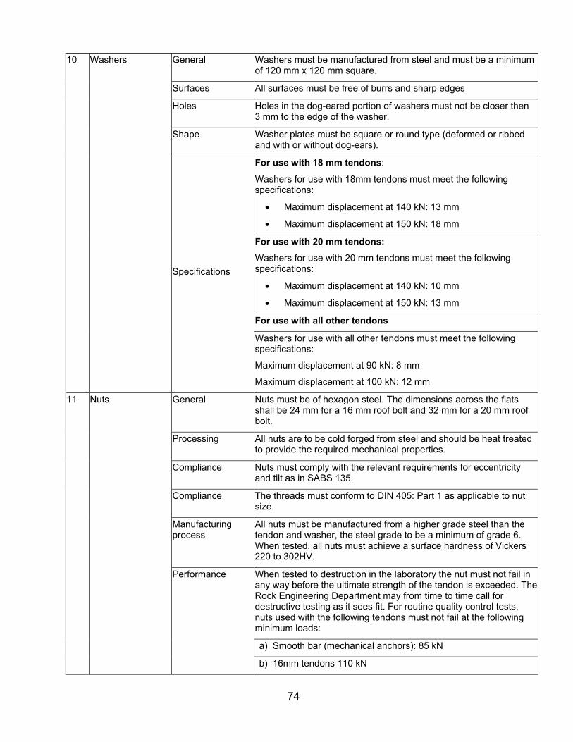
74
General Washers must be manufactured from steel and must be a minimum of 120 mm x 120 mm square.
Surfaces All surfaces must be free of burrs and sharp edges
Holes Holes in the dog-eared portion of washers must not be closer then 3 mm to the edge of the washer.
Shape Washer plates must be square or round type (deformed or ribbed and with or without dog-ears).
For use with 18 mm tendons:
Washers for use with 18mm tendons must meet the following specifications:
• Maximum displacement at 140 kN: 13 mm
• Maximum displacement at 150 kN: 18 mm
For use with 20 mm tendons:
Washers for use with 20 mm tendons must meet the following specifications:
• Maximum displacement at 140 kN: 10 mm
• Maximum displacement at 150 kN: 13 mm
For use with all other tendons
10 Washers
Specifications
Washers for use with all other tendons must meet the following specifications:
Maximum displacement at 90 kN: 8 mm
Maximum displacement at 100 kN: 12 mm
General Nuts must be of hexagon steel. The dimensions across the flats shall be 24 mm for a 16 mm roof bolt and 32 mm for a 20 mm roof bolt.
Processing All nuts are to be cold forged from steel and should be heat treated to provide the required mechanical properties.
Compliance Nuts must comply with the relevant requirements for eccentricity and tilt as in SABS 135.
Compliance The threads must conform to DIN 405: Part 1 as applicable to nut size.
Manufacturing process
All nuts must be manufactured from a higher grade steel than the tendon and washer, the steel grade to be a minimum of grade 6. When tested, all nuts must achieve a surface hardness of Vickers 220 to 302HV.
When tested to destruction in the laboratory the nut must not fail in any way before the ultimate strength of the tendon is exceeded. The Rock Engineering Department may from time to time call for destructive testing as it sees fit. For routine quality control tests, nuts used with the following tendons must not fail at the following minimum loads:
a) Smooth bar (mechanical anchors): 85 kN
11 Nuts
Performance
b) 16mm tendons 110 kN

75
c) 18mm and 20 mm tendons 170 kN
Load indicators One in each ten bolts shall be supplied with a device capable of visually indicating that an installation has been adequately pre-tensioned. During static laboratory testing (not spun or torqued) the indicators must fail at a load of between 45 kN and 55 kN (4.5 to 5.5 tonnes).
Nut break out The nut break out facility must operate at the torque range values
detailed below:
• Bolt Length 0. 9m, 1.2 m - 70 Nm to 90 Nm
Bolt Length 1.5 m, 1.8 m, 2.1 m - 110 Nm to 140 Nm
12 Drill bits General Only the following (nominal) size drill bits may be supplied to mine for the purpose of drilling holes to install ground support material:
For resin tendon applications:
• For 16 mm and 18 mm roof bolts: 22 mm
• For 20 mm roof bolts: 23.5 mm
For cable anchor applications: 36mm
For mechanically anchored roof bolts: 36 or 38mm
All drill bits (borers) must be manufactured with a tolerance of -0/+0.25 mm.
13 Roofbolters Torque The torque on the roofbolter must be between 220 kN to 250 kN.
Thrust The thrust on the roofbolter must be between 12 kN to 18 kN.
Speed The speed of the roofbolter must be 350 rpm to 550 rpm.
RESIN
Capsule All resin must be supplied in capsule form.
Compliance All resin capsules used must conform to SABS 1534:2002.
1 General
Information required
The following information must be shown clearly on each box of resin:
a) Capsule dimensions
b) Expiry date
c) Batch number
d) Spin and hold times
2 Capsule Size Tolerance Capsules must be 19 mm ± 0.5 mm in diameter for use with 16 mm bolts and 23 mm ± 0.5 mm in diameter for use with 20 mm bolts. The tolerance on supplied length must be nominal ordered length +10 /-5 mm when measured between the crimped ends.

76
3 Colour Coding Colour coding Resin types must be identified by a self-colour coding as given below:
• Fast Set – Red
• Slow Set – Yellow
4 Shelf Life General All resins must retain their ability to conform to the performance requirements of this specification and retain sufficient rigidity for insertion with a capsule-loading tube for a minimum period of six months when they are stored in accordance with the manufacturer’s instructions.
General All packing must be capable of withstanding transportation, handling and storage, and general handling associated with the mining environment.
Information required
Each package must be identified with the manufacturer’s name, type of resin, size of capsule, and quantity of capsules, and be of a colour consistent with the resin-type colour code specified above.
5 Packaging
Information display The following additional information must be displayed on all packages in a position that is visible when the packages are stacked:
a. Capsule dimensions
b. Expiry date
c. Batch number
d. Nominal mixing and holding time
e. Shelf life and storage instructions
f. Date of manufacture
g. Batch and time reference
h. Manufacturer’s identification
i. The symbols, risk and safety phrases as required under the Safety Regulations
j. Remedial measures in the event misuse/accident
k. Installation procedure taking into account applicable regulations.
6 Gel and Setting Time
General Gel setting times for different spinning speeds and temperatures should be clearly indicated on the box.
7 Bond Strength and System Stiffness
Performance When tested in SEPT, the minimum bond strength between roof bolt and resin must be 95 kN for 16 mm bar, 120 kN for 18 mm bar and 140 kN for 20 mm bar. The minimum system stiffness must be 60 kN/mm measured between loads of 40 kN and 80 kN, based on underground pull tests.
8 Uniaxial Compressive Strength (UCS)
Performance The UCS of the resin must be greater than 60Mpa when it is measured at least 24 hours after preparation of the test specimens. The number of tests should be determined from the methodology described in this report.
9 Elastic Modulus Performance The elastic modulus of the resin must not be less than 10GPa when it is measured 24 hours after preparation of the test specimens. The required number of tests should be determined from the methodology described in this report.

77
10 Creep Performance The creep of the resin must be no more than 0.12% when it is measured 24 hours after preparation of the test specimens. The required number of tests should be determined from the methodology described in Section 10.4.
11 Shear strength Performance Must meet the SEPT requirements.
The maximum load achieved must not be less than:
125 kN for 20 mm roof bolts
100 kN for 18 mm roof bolts
85 kN for 16 mm roof bolts
The minimum system stiffnesses must be:
20 mm for bolt 60 kN/mm
18 mm for bolt 50 kN/mm
16 mm for bolt 40 kN/mm
ROUTINE TESTS
Mechanical properties
The number of tests should be determined as described in Section 10.4.
Length As a routine test, one roof bolt in every 200 produced must be checked for length using a measuring tape.
Diameter As a routine test, one roof bolt in every 200 produced must be checked for diameter using a Vernier.
Straightness As a routine test, one roof bolt in every 200 produced must be checked for straightness using an appropriate gauge.
Rib height As a routine test, one roof bolt in every 200 produced must be checked for rib height using a Vernier.
Washer The number of tests should be determined as described in Section 10.4.
Thread As a routine test, one roof bolt in every 200 produced must be checked for thread.
1 Roof bolts
Nuts As described in Section 10.4.
Length As a routine test, one resin in every 10 boxes produced must be checked for length using a Vernier.
Diameter As a routine test, one resin in every 10 boxes produced must be checked for diameter using a measuring tape.
2 Resin
Mechanical properties
The number of tests should be determined as described in Section 10.4.
3 Short encapsulated pull testing
Underground See section 2.
3 Laboratory testing Laboratory

78
4 Roofbolters Torque, thrust and speed
As a routine test, roofbolter’s torque, thrust and speed must be checked once every month.
10.2 Compliance with the design Compliance with the design should be checked underground at least once every four weeks. The following parameters should be measured and recorded:
• Spacing of roof bolts using a simple measuring tape; • The use of correct bolt type; • The use of correct resin type; • Correct hole size using a borehole micrometer; • The use of the correct drill bit; and • Correct adjustment of torque, thrust and speed of roofbolters using a
torque wrench, load cell and tachometer, respectively.
10.3 Installation Underground support installation is one of the most important aspects of support performance. The following parameters should be measured and recorded every four weeks using the appropriate instruments, where necessary:
• Correct installation cycle; • Correct spinning-holding times; • Correct insertion of resin; • Correct drilling; • Correct bit size; • Correct rod length and hole length; • Correct flushing; • Correct roof bolt pattern; • Correct time-to-installation; and • Correct resin storage.
10.4 Number of tests required In conjunction with this project on roof support, another SIMRAC project (SIM 040205, Malan et al, 2005) also investigated quality assurance procedures for support products. The approach regarding sample size given below was developed for the SIM 040205 project, but is repeated here for the sake of completeness. The number of samples selected for testing determines the confidence levels that can be derived, and therefore the larger the sample size the better. However, since destructive testing of mine support units is expensive it is

79
important to obtain a balance between confidence levels (and acceptable risk levels) and testing costs. Furthermore, there is an optimal sample size beyond which taking more samples does not significantly improve the confidence level. If the sample size is small, which is typically the case for support testing, a normal distribution cannot be used to obtain these confidence levels and instead the t-distribution needs to be used. The basic procedure is first to test a reasonable number (say 10) samples, in order to obtain an initial crude estimate of the mean X and standard deviation s of the population concerned. The number of additional tests to achieve a desired level of confidence can then be estimated using the following basic criterion: the mean performance of the support unit must be determined such that one is confident (at say the 95 % level) that the calculated mean is within a stipulated margin of error e (say 5 %) of the true mean value. Figure 10-1 below illustrates the t-distribution for the sample, the sample mean X , and the margin of error E = e X . For a 95 % confidence interval, it implies that one is 95 % certain that the sampling error (difference between the sample mean and the true population mean) is less than the margin of error.
XE− E
95 %
Figure 10-1 T-distribution showing the margin of error
The margin of error e for the t-distribution is given as:
nX
ste
⋅= [10-1]
where e is the required margin of error expressed as a fraction of the mean value X (e.g. e = 0.05), s is the standard deviation of the sample, n is the number of samples, and t is a value read off the t-distribution tables (a function of the ‘degrees of freedom’ = n-1, and of the specified ‘2-tailed’ confidence interval say 95 %). Rearranging this equation, it follows that:
2
⋅
⋅=
Xest
nreq [10-2]

80
The minimum number of required tests is given by equation 10-2 above and will be referred to as reqn . Assume an initial number of samples initn are tested with:
reqinit nn < [10-3]
Therefore an additional number of samples addn need to be tested so that
addinitreq nnn += [10-4]
When inserting [10-2], it follows that
initadd nXestn −
⋅⋅
=2
[10-5]
The number of additional samples required to obtain a specific confidence level is a function of the initial sample size, the variability in the results, the confidence levels required, and a criterion for acceptable testing. Note that from this analysis the test quantity is not determined by the total number of units supplied to the mine. Figure 10-2 shows the estimated number of extra tests required, assuming that the standard deviation of the test results are 10, 15 or 20 % of the mean value and the required confidence level is 90 %. The results show that, regardless of the variability, testing fewer than five samples initially will lead to a considerable number of additional tests. Large variability in the initial results will naturally lead to a larger number of additional tests. Figure 10-3 shows the effect of two different required confidence levels on the extra tests required, assuming the standard deviation divided by the mean of the test results is 15 % and the same acceptance criterion is used. The results show that approximately twice as many extra tests will be required to achieve a 95 % confidence level relative to a 90 % level. For laboratory tests on tendons, for example, it is proposed that the initial number of tests should be 10, on the bases of the arguments set out above. If the standard deviation and the mean of the samples are calculated, Equation [10-5] will give an indication of whether additional tests are required. If Equation [10-5] gives a negative number, the initial sample size of 10 will be adequate.
81
EXTRA TESTS REQUIRED(90% Confidence Level)
010
20304050
607080
90100
0 5 10 15 20 25 30 35 40INITIAL NUMBER OF TESTS
EXTR
A TE
STS
REQ
UIRE
D SD/MEAN=10% = 15% = 20%
Figure 10-2 Estimated extra tests required for a confidence level of 90 %
EXTRA TESTS REQUIRED(SD/MEAN=15%)
01020
3040506070
8090
100
0 5 10 15 20 25 30 35 40INITIAL NUMBER OF TESTS
EXT
RA
TES
TS R
EQ
UIR
ED 90%
95%
Figure 10-3 Estimated extra tests required for confidence levels of 90 % and 95 % In actual fact, it can be true that Figures 10-2 and 10-3 significantly overstate the total number of tests actually required to satisfy the confidence criteria. Suppose an additional say 40 tests are estimated. If these additional tests are carried out in batches of say 5 at a time, and the pooled results are used to re-compute the sample mean X and standard deviation s, Figure 10-4 below can be used to decide at any stage whether sufficient tests have in fact been carried out. The x-axis of this graph is the current value of s / e X . A further issue that can arise is that for certain values (e.g. the tensile strength of a roofbolt) one is concerned only in establishing a reliable minimum value and a 1-tailed t-distribution is acceptable. In such cases, reading off a 90 % confidence level curve will in fact give 95 % confidence in correctly establishing a lower bound of the variable concerned.

82
0
5
10
15
20
25
30
35
0.0 1.0 2.0 3.0 4.0
s/eX
Min
. no.
of t
ests
(n)
95 % conf (2-sided)90 % conf (2-sided)
Figure 10-4 Actual minimum no of tests, using pooled values of X and s
11 References Altounyan P.F.R., Bigby D.N., Hurt K.G. and Peake H.V. (1997). Instrumentation and procedures for routine monitoring of reinforced mine roadways to prevent falIs of ground. In: Dhar BB, Bhowmick BC. eds. Proceedings of the 27th International Conference of Safety in Mines Research Institutes. Vol. 2. New Delhi, India, pp. 759-766.
Altounyan P.F.R. and Taljaard, D. (2001). Developments in controlling the roof in South African coal mines – a smarter approach. The Journal of The South African Institute of Mining and Metallurgy, January/February, pp.33-40.
American Society for Testing and Materials. Standard test method for rockbolt anchor pull test, Standard D4435-04.
American Society for Testing and Materials. Standard specification for roof and rockbolts and accessories, Standard F432-04.
American Society for Testing and Materials. Standard test method for rockbolt long-term load retention, Standard D4436-04.
Aziz N. and Webb B. (2003). Study of load transfer capacity of bolts using the short encapsulation push test, Proceedings of the 22nd International Conference on Ground Control in Mining, Morgantown, WV, USA.
Barton, N., Lien, R. and Lunde, J. (1974). Engineering classification of rock masses for the design of tunnel support. Rock Mechanics 6, 189-236.
Bieniawski, Z. T. (1987). Strata control in mineral engineering, John Wiley and Sons. pp. 29-37.
Bieniawski, Z.T. (1973). Engineering classification of jointed rock masses. The Civil Engineer in South Africa, December.

83
Bigby O.N. (1997). Developments in British rockbolting technology. Coal International, Rockbolting Technology, May, pp. 111-114.
Biron, C. and Arioglu, E. (1985). Madenlerde tahkimat isleri ve tasarimi. Istanbul Technical University. Birsen Kitabevi. Istanbul.
British Coal Operations Department (1994). Optimisation of cable bolting and rockbolting material properties, Final Report to the Commission of the European Communities Directorate General for Energy.
British Standards Institution (1996). Strata reinforcement support system components used in coal mines. Part 1. Specification for rockbolting. British Standard BS7861: Part 1.
Buddery, P. (1989). Fundamental principles of roof bolting in South African Collieries. Advances in rock mechanics in underground coal mining. SANGORM Symposium, September.
Buddery, P. S. and Oldroyd, D. C. (1992). Development of roof and floor classification applicable to collieries. Eurock’92. Thomas Telford, London.
Campoli A.A., Mills P.A., Todd P. and Dever K. (1999). Resin annulus size effects on rebar bolt pull strength and resin loss to fractured rock. In: Peng SS, Mark C. eds. Proceedings of the 18th International Conference on Ground Control in Mining. Morgantown, WV: West Virginia University, pp. 222-231.
Canbulat, I. (2004). An investigation into the roof and support behaviour in South African collieries for the design of optimum support systems. PhD Thesis, University of Pretoria.
Canbulat, I. and van der Merwe, J.N. (2000). Safe mining face advance and support installation practice in mechanical miner workings under different geotechnical conditions. SIMRAC Project Final Report COL609. Report No. 2000-0154. April.
Canbulat, I. and Dlokweni, T. (2003) Roof rating systems being used in South Africa. ISRM 2003–Technology Roadmap for Rock Mechanics, South African Institute of Mining and Metallurgy, pp 175-184. September.
Canbulat, I. and Jack, B.W. (1998). Review of current design methodologies to improve the safety of roof support systems, particularly in the face area, in collieries. SIMRAC Final Project Report, COL 328, December.
Canbulat, I. and van der Merwe, J.N., van Zyl, M., Wilkinson, A., Daehnke, A. and J. Ryder. (2003). The development of techniques to predict and manage the impact of surface subsidence. Final Project Report, COALTECH 2020, Task 6.9.1. January. 211 pp.
Canbulat, I., Wilkinson, A. and Prohaska, G.P. (2003). An investigation into the support systems in South African collieries. Safety in Mines Research Advisory Committee (SIMRAC). Project No: SIM020205. Quarterly report, June.
Coats, D.F. and Cochrane, T.S. (1971). Rockbolting, research and design specifications, Canadian Mining Journal, March.
Deep Mines Coal Industry Advisory Committee (DMCIDC). (1996). Guidance on the use of rockbolts to support roadways in coal mines. HSE Books, UK.
Deere, D.U. (1964). Technical description of cores for engineering purposes. Rock Mechanics and Engineering Geology. Volume 1, Number 1, 17-22.
Dejean, M. and Raffoux, J.F. (1976). Role of rockbolting and parameters in its selection, Mining drifts and tunnels: Tunnelling’76, London, Institute of Mining and Metallurgy. pp. 321-327.
Dunham, R.K. (1976). Anchorage tests on strain-gauged resin bonded bolts. Tunnels and Tunnelling 8 (6), pp. 73-76.
Fabjanczyk, M. W., and Tarrant, G. C. (1992). Load transfer mechanisms in reinforcing tendons. In: Aziz NI, Peng SS, eds. Proceedings of the 11th International Conference on Ground Control in Mining. Wollongong, New South Wales, Australia: University of Wollongong, pp. 212-219.
Fairhurst, C. and Singh, B. (1974). Roof bolting in horizontally laminated rock. Eng Min J Feb: 80-90.
Franklin, J. and Woodfiled, P. (1971). Comparison of a polyester resin and a mechanical rockbolt anchor. Transactions of the Institute of Mining and Metallurgy, (A)8-:91-A100.

84
Frith R. (1998). Strata engineering summary. Australian Coal Association Research Program (ACARP) Technical Seminar Course Notes.
Frith, R. and Thomas, R. (1998). The pre-tensioning pedigree. Australia's Mining Monthly Supplement-Underground Equipment and Technology June, pp. 68-72.
Fuller, P.G. (1999). Keynote lecture: roof strata reinforcement-achievements and challenges. In: Proceedings of the Rock Support and Reinforcement Practice in Mining. Balkema, pp. 405-415.
Gale W.J. (1991). Strata control utilizing rock reinforcement techniques and stress control methods, in Australian coal mines. The Mining Engineer Jan:247-253.
Gale, W. and Fabjanczyk, M.W. (1993). Design approach to assess coal mine roadway stability and support requirements. In: Proceedings of the Eighth Australian Tunnelling Conference (Sydney, Australia).
Gale, W., Fabjanczyk, M. W., Tarrant, G. C. and Guy, R. J. (1992). Optimisation of reinforcement design of coal mine roadways. In: Aziz NI, Peng SS, eds. Proceedings of the 11th International Conference on Ground Control in Mining. Wollongong, New South Wales, Australia: University of Wollongong, pp. 272-279.
Gercek, H. (1982). Stability of intersection in room and pillar coal mining. Ph.D. Thesis, Pennsylvania State University. WV. 186 pp.
Gerdeen, J.C., Snyder, V.W., Viegelahn, G.L. and Parker, J. (1979). Design criteria for roof bolting plans using fully resin-grouted non-tensioned bolts to reinforce bedded mine roof. Volume III: Experimental model studies; Volume IV: Theoretical analysis. Houghton, MI: Michigan Technological University. U.S. Bureau of Mines contract No. J0366004.
Guo, S. (1996). Development and improvement of numerical models for roof supports in Underground Coal Mines, Ph.D. Thesis, WVU, Morgantown, WV, pp. 31-42.
Hagan P. (2004). Variation in the load transfer of fully encapsulated rockbolts, Proceedings of the 23rd International Conference on Ground Control in Mining, Morgantown, WV, USA.
Hagan, P.C. (2003a). The effect of resin annulus on anchorage performance of fully encapsulated rockbolts, in Technology roadmap for rock mechanics, Proceedings ISRM 2003 Conference, pp 447-450 (South Africa Inst. Min. and Metal.: Johannesburg).
Hagan, P.C. (2003b). Observations on the differences in load transfer of a fully encapsulated rockbolt. .Proceedings of 1st Australasian Ground Control in Mining Conference, November.
Hanna, K. and Conover, D.P. (1988) Design of coal mine entry intersections. Paper at SME Annual Meeting, Phoenix, AZ, January, 1998.
Hayes A.W. and Altounyan P.F.R. (1995). Strata control the state-of-the-art. Mining Technology, Institute of Mining Engineers 77(892): 354-358.
Karabin, G.J. and Debevec W.J. (1976) Comparative evaluation of conventional and ersin bolting systems. U.S. Department of Labor, Mine Enforcement and Safety Administration, IR 1033.
Kent F.L., Coggan J.S. and Altounyan P.F.R. (1999b) Investigation into factors affecting roadway deformation in the Selby coalfield. In: Proceedings of the Geotechnical and Geological Engineering, pp. 273-289.
Kent L., Cartwright P.B. and Bigby D.N. (1999a). Tunnel deformation monitoring "action levels" in coal mines for support/reinforcement design. In: Peng SS, Mark C, eds. Proceedings of the 18th International Conference on Ground Control in Mining. Morgantown, WV: West Virginia University, pp. 98-107.
Lang T.A. and Bischoff J.A. (1982). Stabilization of rock excavations using rock reinforcement. In: Proceedings of the 23rd U.S. Rock Mechanics Symposium. pp. 935-944.
Lauffer, H. (1958). “Gebirgsklassifizierung fur den Stollenbau,” Geologie and Bauwesen, Vol. 24, No. 1, pp. 46-51.
Lorig, L.J. (1985). A simple numerical representation of fully bonded passive rock reinforcement for hard rocks. Computers and Geotechnics 0266-352X. Great Britain: Elsevier.
Luo, J., Haycocks, C., Karmis, M. and Westman, E. (1998). A critical overview of U.S. rockbolting practices. Third International Symposium, Roof bolting in mining. Aachen Germany, June 3 – 4.

85
MaIeki H., Signer S.P., King M. and Edminster P. (1994). Evaluation of support performance in a highly stressed mine. In: Peng SS, ed. Proceedings of the 13th International Conference on Ground Control in Mining. Morgantown, WV: West Virginia University, pp. 9-17.
Maleki H., Carlisle T., Hunt G. and Agapito J.F.T. (1987). A novel ground control program at Plateau Mining Company. In: Peng SS, ed. Proceedings of the 6th International Conference on Ground Control in Mining. Morgantown, WV: West Virginia University, pp. 118-125.
Maleki, H. (1992). Significance of bolt tension in ground control, Proceeding of the Rock Support in Mining and Underground Construction, Balkema, pp. 439-449.
Mark C. (1998). Comparison of ground conditions and ground control practices in the USA and Australia. In: Peng SS, ed. Proceedings of the 17th International Conference on Ground Control in Mining. Morgantown, WV: West Virginia University, pp. 63-71.
Mark C. and Barczak T.M. (2000). Fundamentals of coal mine roof support. In: New Technology for Coal Mine Roof Support. Pittsburgh, PA: U.S. Department of Health and Human Services, Public Health Service, Centers for Disease Control and Prevention, National Institute for Occupational Safety and Health, DHHS (NIOSH) Publication No. 2000-151, IC 9453.
Mark C., Dolinar D.R. and Mucho T.P. (2000). Summary of field measurements of roof bolt performance. In: New Technology for Coal Mine Roof Support. Pittsburgh, P A: U.S. Department of Health and Human Services, Public Health Service, Centers for Disease Control and Prevention, National Institute for Occupational Safety and Health, DHHS (NIOSH) Publication No. 2000-151, IC 9453.
Mark, C. (1982). A physical model study of coal mine roof using the base friction technique. PhD Thesis. University Park, PA: The Pennsylvania State University.
Mark, C. (2000). Design of roof bolt systems. In: New technology for coal mine roof support. Pittsburgh, PA: U.S. Department of Health and Human Services, Public Helath Service, Centres for Disease Control and Prevention, National Institute for Occupational Safety and Health, DHHS, (NIOSH) Publication No. 2000-151, IC 9453.
Mark, C. (2001). Overview of ground control research for underground coal mines in the USA. 17th International Mining Congress and Exhibition of Turkey. June.
Mark, C. (2002). The introduction of roof bolting to U.S. underground coal mines (1948-1960): A cautionary tale. In: Peng SS, ed. Proceedings of the 21th International Conference on Ground Control in Mining. Morgantown, WV: West Virginia University,
Mark, C. (2004). Personal communication.
Mark, C., Chase, F. and Molinda, G. (1994). Design of longwall gate entry systems using roof classification. New technology for ground control, Proceedings: USBM Technology Transfer Seminar, Washington D.C., pp. 5-17.
Mark, C., Compton, C., Oyler, D. and Dolinar, D. R. (2002). Anchorage pull testing for fully grouted roof bolts. In: Peng SS, ed. Proceedings of the 13th International Conference on Ground Control in Mining. Morgantown, WV: West Virginia University.
McHugh E. and Signer S.P. (1999). Roofbolt response to shear stress: laboratory analysis. In: Peng SS, Mark C, eds. Proceedings of the 18th International Conference on Ground Control in Mining. Morgantown, WV: West Virginia University, pp. 232-238.
Minerals Bureau, (2003). Operating and developing coal mines in the Republic of South Africa. Department of Minerals and Energy. South Africa.
Minney, D. and Munsamy, L. (1998). Personal communication.
Minney, D., van Wijk, J. and Vorster, B. and Koen, F. (2004). Personal communication.
Molinda, G. M. and Mark, C. (1994). The coal mine roof rating (CMRR): A practical rock mass classification for coal mines. In: Peng SS, ed. Proceedings of the 12th International Conference on Ground Control in Mining. Morgantown, WV: West Virginia University, pp. 92-103.
Molinda, G., Mark, C., and Dolinar, D. (2000). Assessing coal mine roof stability through roof fall analysis. In: New technology for coal mine roof support. Pittsburgh, PA: U.S. Department of Health and Human Services,

86
Public Health Service, Centres for Disease Control and Prevention, National Institute for Occupational Safety and Health, DHHS, (NIOSH) Publication No. 2000-151, IC 9453.
Molinda, G., Mark, C., Bauer, E., Babich, D. and Papas, D. (1998). Factors influencing intersection stability in U.S. coal mines. In: Peng SS, ed. Proceedings of the 17th International Conference on Ground Control in Mining. Morgantown, WV: West Virginia University, pp. 267-275
O’Brien, B.J. (2003). The effect of profile on rockbolt performance. BSc thesis. University of New South Wales. Australia.
O’Connor, D. (2004). Personal communication.
O’Connor, D., van Vuuren, J. and Altounyan, P. (2002). Measuring the effect of bolt installation practice on bond strength for resin anchored rockbolts. SANIRE 2002 Symposium. Re-Defining the Boundaries. September.
Obert, L. and Duvall, W. I. (1967). Rock mechanics and the design of structures in Rock. John Wiley and Sons.
Panek L.A. (1964). Design for bolting stratified roof. Trans SME, 229. Littleton, CO: Society for Mining, Metallurgy, and Exploration, Inc., pp. 113-119.
Parker, J. (2001). Selecting a roof bolting system, Part 2, AGGMAN, November, pp. 16-21.
Peng S.S. (1998). Roof bolting adds stability to weak strata. Coal Age Magazine Dec: pp. 32-38.
Peng S.S. and Guo L.B. (1989). Design criteria for resin bolting. SME preprint 89-166. Littleton, CO: Society for Mining, Metallurgy, and Exploration, Inc.
Peng, S.S. (1986). Coal mine ground control, 2nd edition, John Wiley and Sons.
Pile, J., Bessinger, S., Mark, C. and Tadolini, S. (2003). Short-encapsulation pull tests for roof bolt evaluation at an operating coal mine. In: Peng SS, ed. Proceedings of the 22nd International Conference on Ground Control in Mining. Morgantown, WV: West Virginia University, pp. 226-232.
Raffoux, J.S. (1971). Resin bonded bolting in French coal mines. Proc. Symp. On Rockbolting, Wollongong, Australia, pp. 18-25.
Roberts, D.P. (2000). Finite element modelling of rockbolts and reinforcing elements. PhD Thesis submitted to the University of Wales, Swansea.
Roberts, D.P. (1995). Testing of mining tunnel support elements and systems for hard rock mines, Master of Science in Engineering to the Department of Mechanical Engineering, University of Natal, South Africa.
Serbousek, M.O. and Signer, S.P. (1987). Linear load-transfer mechanisms of fully grouted roof bolts. U.S. Bureau of Mines. R19135.
Siddall, R. G. and Gale, J. (1992). Strata control – A new science for an old problem. Institution of Mining Engineers and the Institution of Mining and Metallurgy Annual Meeting. UK, January.
Siddall, R.G. (1992). Roofbolting – supply side technology. Institution of Mining Engineers and the Institution of Mining and Metallurgy Annual Meeting. Harrogate, UK, June.
Signer S.P. (1990). Field verification of load transfer mechanics of fully grouted roof bolts. Spokane, WA: U.S. Department of the Interior, Bureau of Mines, RI 9301.
Signer S.P., Mark C., Franklin G. and Hendon G. (1993). Comparisons of active versus passive bolts in a bedded mine roof. In: Peng SS, ed. Proceedings of the 12th International Conference on Ground Control in Mining. Morgantown, WV: West Virginia University, pp. 16-23.
Signer, S.P. and Jones, S.D. (1990). A case study of grouted roof bolt loading in a two-entry gateroad, In: Peng SS, ed. Proceedings of the 9th International Conference on Ground Control in Mining. Morgantown, WV: West Virginia University, pp. 35-41.
Signer, S.P. and Lewis, J.L. (1998). A case study of bolt performance in a two-entry gateroad. In: Peng SS, ed. Proceedings of the 17th International Conference on Ground Control in Mining. Morgantown, WV: West Virginia University, pp. 249-256.

87
Signer, S.P., Cox D. and Johnston, J. (1997). A method for the selection of rock support based on bolt loading measurement. In: Peng SS, ed. Proceedings of the 16th International Conference on Ground Control in Mining. Morgantown, WV: West Virginia University, pp. 183-190.
Sinha R.S. (1989) Underground structures design and instrumentation. Denver.
Smith, W. (1993). Roof control strategies for underground coal mines, U.S. Bureau of Mines. IC 9351 USBM.
Snyder, V.W., Geerden, J.C. and Viegelahn, G.L. (1979). Factors governing the effectiveness of roof bolting systems using fully resin-grouted non-tensioned bolts. In Proceedings 20th Symposium on Rock Mechanics, pp. 607-613.
Spann, H. P. and Napier, J. A. L. (1983). The influence of different bolt patterns and anchor types on the deflection of a laminated beam.
St. John, C.M. and van Dillen, D.E. (1983). Rockbolts: a new numerical representation and its application in tunnel design. 24th U.S. Symp. Rock Mech.
Stankus J.C. (1991). Tensioned point anchor resin system versus non-tensioned fully grouted rebar-two case studies. In: Peng SS, ed. Proceedings of the 10th International Conference on Ground Control in Mining. Morgantown, WV: West Virginia University, pp. 65-76.
Stankus J.C. and Peng S.S. (1996). A new concept for roof support. Reprint from Coal Age Magazine, September.
Stillborg, B. (1986). Professional Users Hand Book for Rockbolting, Trans Tech Publications, vol. 15, pp. 55-89.
Tadolini S.C. (1998). The effects of reduced annulus in roof bolting performance. In: Peng SS, ed. Proceedings of the 17th International Conference on Ground Control in Mining. Morgantown, WV: West Virginia University, pp. 230-236.
Tadolini S.C. and Ulrich B.F. (1986). Evaluation of bearing plates installed on full-column resin-grouted bolts. U.S. Department of the Interior, Bureau of Mines, RI 9044.
Tadolini, S.C. and Dolinar D.R. (1991). Thrust bolting: a new innovation in coal mine roof support. In: Peng SS, ed. Proceedings of the 10th International Conference on Ground Control in Mining. Morgantown, WV: West Virginia University, pp. 76-84.
Terzaghi, K. (1946). Rock defects and loads on tunnel support. Rock tunnelling with steel support. Commercial Shearing Co., Youngstown, Ohio.15-99.
Tincelin, E. (1970). Roof bolting recommendations. Exploration of mineral deposits and mineral proceedings. Parley of Cooperation and Industrial Promotion. Sydney. May.
Tully, D.M. (1987). The Application of scale model studies in the design of rockbolting system for Mine Roadways, 28 U.S. Symposium on Rock Mechanics, June, pp. 781-788.
UK Health and Safety Executive (1996). Guidance on the use of rockbolts to support roadways in coal mines. UK Health and Safety Executive, Deep Mine Coal Industry Advisory Committee. 16 pp.
Ulrich B.F., Wuest, J. and Stateham R.M. (1989). Relationships between annulus thickness and the integrity of resin grouted bolts. Denver, CO: U.S. Department of the Interior, Bureau of Mines, RI 9253.
Unal, E. (1984). Empirical approach to calculate rock loads in coal mine roadways. In: Peng SS, ed. Proceedings of the 5th International Conference on Ground Control in Mining. Morgantown, WV: West Virginia University, pp. 232-246.
Van der Merwe, J.N. (1989). A probabilistic approach to the design of coal mine roof support systems. Advances in rock mechanics in underground coal mining. SANGORM Symposium, September.
Van der Merwe, J.N. (1995). Practical coal mining strata control. A guide for managers. Johannesburg, South Africa, November.
Van der Merwe, J.N. (1998). Practical coal mining strata control. A guide for managers. And supervisors at all levels. Second edition. Johannesburg, South Africa, November.
Van der Merwe, J.N. (2001). Personal communication.

88
Van der Merwe, J.N. and Madden, B.J. (2002). Rock engineering for coal mining. Safety in Mines Research Advisory Committee (SIMRAC). SAIMM Special Publications Series 7. April.
Van der Merwe, J.N., van Vuuren, J.J., Butcher, R. and Canbulat, I. (2001). Causes of falls of roof in South African collieries. SIMRAC, Department of Minerals and Energy, Johannesburg, South Africa Final Project Report, Report No: COL613. March 2001.
Vervoort, A. M. J. (1990). Falls of ground in South African collieries during the Period 1970 – 1988. Part 3: Effect of exploitation method. Chamber of Mines Research Organisation (COMRO) Internal Report, Project Report No. 7/90, Project No. CC8S03, January.
Wagner, H. (1985). Design of roof bolting patterns. Chamber of Mines workshop on roof bolting in collieries. Republic of South Africa. Johannesburg.
Whitaker, A. (1998). Critical assessment of past research into rockbolt anchorage mechanisms. Unpublished BE (Mining Engineering) thesis, University of New South Wales, Sydney.
Wickham, G.E., Tiedemann, H.R. and Skinner, E.H. (1972). Support determination based on geological predictions. Proceedings, rapid Excavation and Tunnelling Conference, AIME, New York, pp. 43-64.
Windsor, C. and Thompson A. (1997). Rock reinforcement practice, advanced course. Rock Technology Pty Limited. Australia.
Wright F.D. (1973). Roof control through beam action and arching. In: Given lA, ed. SME Mining Engineering Handbook 1(13). Littleton, CO: Society for Mining, Metallurgy, and Exploration, Inc., p. 80.
Wullschlager, D. and Natau, O. (1983). Studies of the composite system of rock mass and non-prestressed grouted rockbolts, Proceeding of the International Symposium on Rockbolting, September, 1983, pp. 75-85.
Yassien, A.M. (2003). 2-D numerical simulation and design of fully grouted bolts for underground coal mines. PhD Thesis. West Virginia University, Morgantown. 180 pp.
Zhang, Y. (2003). 3-D Numerical simulation and design of tensioned roof bolting for underground coal mines. PhD Thesis. West Virginia University, Morgantown. 197 pp.