roofing installation guide - · pdf file2 roofing installation guide maxilite p10, rake tile,...
TRANSCRIPT

2
ROOFING INSTALLATION GUIDE
MAXILITE P10, RAKE TILE, HIP AND RIDGE TILE:
Read all instructions prior to installing any siding product. Failure to install and fi nish this product in accordance with all local building codes, regulations and MAXITILE written application may lead to personal injury, affect system performance, violate local building codes, and void the product warranty.
We suggest that you read these instructions at least twice.
STORAGE: MAXITILE products must be stored fl at and off ground prior to
installation. Protect products from direct weather exposure.
To prevent damage, keep roofi ng products in the original packaging
until it is ready to install. Use the plastic bonnet provided to keep the
product dry and to prevent moisture from setting on the surface.
If MAXITILE products are stored outside, they should be protected
with an additional waterproof covering.
Field tiles, rake tiles, hip and ridge tiles must be installed
with a minimum 4 inches head lap. Twenty-four pieces of
fi eld tile cover one square (100 sq. ft.), 5 squares per pallet.
216 rake, hip or ridge tiles per pallet, covers 360 lineal feet.
Installed weight of the fi eld tile is approximately 345 lbs/sq.
MAXILITE P10™

www.maxitile.com | MAXILITE P10 3
BIRD STOP, HIP AND RIDGE SEAL:The MAXILITE P10 bird stop is 5 feet long and made of metal. Install only one bird stop at a time. If there is an
alignment problem, the next piece can be slid or right to get the proper fi t with the tile. The bird stop can also be cut
in shorter lengths to further ease alignment. Hip and ridge seals are plastic and come in black only.
• MAXITILE recommends that all cutting of products be performed outdoors. Use mechanical ventilation
when possible.
• For irregular cuts and holes, use a jig saw or a hole saw with a masonry blade. Special round openings can be
made by drilling several holes around the circumference of the desired opening and tapping out center. Always
cut over the top of a barrel of tile.
CUTTING:Refer to the Material Safety Data Sheet (MSDS) for important safety practices prior to using any roofi ng product.
WARNING: AVOID BREATHING SILICA DUST.MAXITILE roofi ng products may contain trace amount (<0.5%) of crystalline silica, which is known to the State of California to cause cancer and is considered by IARC and NIOSH to be a cause from some occupational sources. Breathing excessive amounts of respirable silica dust can also cause a disabling and potentially fatal lung disease called silicosis, and has been linked with other diseases. Some studies suggest smoking may increase these risks. During installation or handling: (1) work in outdoor areas with ample ventilation; (2) use fi ber cement shears for cutting or, where not feasible, use a dust-reducing circular saw attached to a HEPA vacuum; (3) warn others in the immediate area; (4) wear a properly-fi tted, NIOSH-approved dust mask or respirator (e.g. N-95) in accordance with applicable government regulations and manufacturer instructions to further limit respirable silica exposures. During clean-up, use HEPA vacuums or wet methods, never dry sweep. For further information, refer to our installation guide and Material Safety Data Sheet available at www.maxitile.com or by calling (800) 338-8453 . FAILURE TO ADHERE TO OUR WARNINGS, MSDS, AND INSTALLATION GUIDES MAY CAUSE SERIOUS PERSONAL INJURY OR DEATH.
• For score-and snap cutting, use a carbide tipped
scoring tool or a sharp knife:
Using a straight edge as a guide, carefully draw
the scoring tool several times towards yourself,
applying even pressure.
Bend upwards and break.
• A HEPA vacuum should be used when cleaning up dry debris and dust from cutting area. Do not use
compressed air, broom or brush. If you consider sweeping, wet down the fl oor and debris with a fi ne mist
to suppress dust during sweeping. All scrap, cutoffs and debris should be disposed of in a covered container
protected from the elements according to local codes. No special handling is required.
4
PITCH:3:12 minimum, 21:12 maximum. For pitches below 3:12, MAXILITE P10 must be installed over an approved waterproof covering (including battens and counter battens) complying with the applicable building code.
ROOF DECK:MAXILITE P10 must be installed over code complying solid wood sheathing. Minimum ½ inch rated plywood decking is recommended for use with standard roof. See ICC Evaluation Report for fi re classifi cation.
DECK PREPARATION:• Felt must be installed in a manner to allow water to run off only at the eave. Underlayment must
be installed in accordance with the applicable building code.
• Install the following nailers:
At gables: 2 inches X 2 inches and must be nailed approximately 1 inch from edge. At hips: 2 inches X 6 inches on edge, holding back 6 inches from eave. At ridge: 2 inches X 4 inches on edge plus 1 inch X 2 inches.
• Wrap gable, hip and ridge nailers with non-perforated Type II (commonly called No. 30) felt in accordance with ASTM D 226.
• Install base fl ashing around pipes, vents, chimneys, etc. Skylights should have a 2 inches X 6 inches curb to fl ash against using same type of fl ashing as chimneys.
• Check to make sure that the roof is square. Apply horizontal chalk lines. The fi rst chalk line should be 22 inches up from the eave, 23 inches if there are gutters. Maximum spacing for the remaining lines is 20 inches.
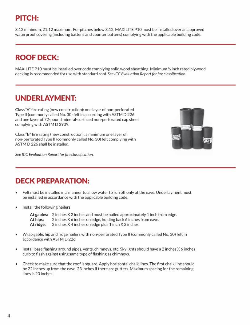
UNDERLAYMENT:Class “A” fi re rating (new construction): one layer of non-perforated Type II (commonly called No. 30) felt in according with ASTM D 226 and one layer of 72-pound mineral-surfaced non-perforated cap sheet complying with ASTM D 3909.
Class “B” fi re rating (new construction): a minimum one layer of non-perforated Type II (commonly called No. 30) felt complying with ASTM D 226 shall be installed.
See ICC Evaluation Report for fi re classifi cation.

www.maxitile.com | MAXILITE P10 5
FASTENERS:Nails and screws must be corrosion-resistant, preferably hot-dipped galvanized for best results, in accordance with local building codes. MAXITILE is not responsible for corrosion resistance of fasteners.
MAXITILE products can be hand nailed using a smooth faced hammer, never use a waffl e hammer, and fastened with pneumatic tools. When hand nailing, fi rst perforate the opening to be used for fastening in order to avoid accidental breakage of the roofi ng product.
Always drive fasteners perpendicular to roofi ng and solid deck. Do not over-drive under drive fastener heads and never drive fastener in at an angle. Fastener head must be fl ush on the surface of the product (no air space). If fastener is countersunk, patch fastener hole and add a fastener. Repair nail-sizes holes by fi lling with adhesive.
• Exposed Fastener: 4-1/2 inches long (114.3 mm), 0.175 inch shank diameter (4.44 mm), corrosion-resistant lag screw with 0.375 inch diameter heads (9.52 mm) with 1 ½ inches X 1 ½ inches galvanized metal washer with neoprene brushing.
• Hidden Fastener: Ring-shank nails, a minimum of 1-3/4 inches (44.45 mm) long and having 0.130 inch diameter (3.30 mm) shank, with a 1 inch (25.4 mm) X 1 inch (25.4 mm) galvanized cap washer (Cap-n-nail). In lieu of nails, No. 11 gauge (3.0 mm) (0.12 inch diameter shank), 1-3/4 inches long (44.45 mm), corrosion-resistant screws having 0.375 inch diameter heads (9.5 mm), with a neoprene-lined washer can be used.
• Adhesive: Polyurethane construction adhesive conforming to AFG-01, ASTM D 557 or ASTM D 3498.
• Wind Clip: Use a wire clip, 1/8 inch diameter conforming to ANSI 1075.
• Nails: Corrosion-resistant 8d common nails.

6
INSTALLATION OF FIELD TILE FOR WIND SPEED 60-100 MPH:MAXILITE P10 roofi ng tile is applied with the staggered joint installation method.
1. On gabled roofs, before installing fi eld tile, the trim tile should be installed at the gable.
2. As a general rule, begin by applying fi eld tile at a gable and run toward a valley, hip or wall.
3. Start by installing a full width six corrugation tile at the lower edge of the gable with an overhang of 1 inch at the gable and 2 inches at the eave (1 inch if gutters). Apply the following tiles in the fi rst course by side lapping one full corrugation.
4. You may start at either end of the roof.
5. Place the exposed fastener through the top of each corrugation behind the bird stop or in the eave course (fi rst course only) into the roof deck, a minimum 2 inches from the bottom edge. Then install the hidden fastener through at each valley of corrugation of the each panel located 2 inches from the top edge of the tile panel. Avoid over tightening the fasteners to prevent breakage of the panel. The fasteners should only be tightened moderately. Cover the fastener heads with adhesive. (The exposed fastener can also be applied in last course if desired).
6. Before laying the next course, apply a 1 inch wide dab of adhesive to the side slope of each corrugation (horizontal side lapping), and a thick bead of adhesive on every overlapped corrugation.
7. Cut one full corrugation of fi eld tile and start the second course with this three-corrugation panel (only the fi rst tile panel). Install the tile with a minimum 4 inches head lap over the previous course. Apply adhesive (review step 6) and place a full width panel continued until fl ush the rake edge.
8. The third course should be started with a fi eld tile cut vertically in half. Repeat step 7.
9. The fourth course is installed as the fi rst course. Repeat steps 3 to 8 until reaching the edge.
10. For all fi eld tile application, install the hidden fastener at each valley of corrugation of the panel located 2 inches from the top edge of the tile panel. Also a wind clip at the lower edge of each overlapping corrugation may be installed.
Incorrect Correct

www.maxitile.com | MAXILITE P10 7
INSTALLATION OF FIELD TILE FOR WIND SPEED > 110 MPH:1. Prior to installing fi eld tiles on gabled roofs, the trim tile should be installed at the gable.
2. As a general rule, begin by applying fi eld tile at a gable and run toward a valley, hip or wall.
3. Start by installing a full width six-corrugation panel at the lower edge of the gable with an overhang of 1 inch at the gable and 2 inches at the eave (1 inch if there are gutters). Apply the following tiles in the fi rst course by side lapping one full corrugation.
4. In high wind areas, the fi eld and ridge trim tile should be installed with the laps facing downwind of the prevailing wind direction.
5. Place the exposed fastener through the top of each corrugation either behind the bird stop or in the eave course (fi rst course) into the roof deck, a minimum 2 inches from the bottom edge. Then install the hidden fastener, secured through every other valley of corrugation of the panel located 2 inches from the top edge of the tile panel. Avoid over tightening fasteners to prevent breakage of tile panel. The fasteners should only be tightened moderately. Cover the fastener heads with adhesive.
Also a 1 inch wide by minimum ¼ inch thick dab of adhesive may be applied to the sides of each barrel and a thick bead on every overlapped barrel, before laying the next course.

6. Cut one full barrel of a fi eld tile and start the second course with this fi ve corrugations tile (only the fi rst tile panel). Install the tile with a minimum 4 inches head lap over the previous course and place an exposed fastener on the fi rst barrel at 2 inches from the lower edge. You can apply adhesive (review step 5) and place a full width tile continued until fl ush the rake edge.
7. The third course should be started with a fi eld tile cut vertically in half. Repeat step 6.
8. The fourth course is installed the same as the fi rst course. Repeat steps 3 to 7 until reaching the ridge.
9. For all fi eld tiles, install the hidden fastener at every other valley of corruption of the panel located 2 inches from the top edge of the tile panel. Also can install an exposed fastener at the top of every crown corrugation. A wind clip must be installed at the lower edge of each overlapping corrugation.

www.maxitile.com | MAXILITE P10 9
The following is only a suggestion and is not intended to be a set of instructions. Each fl ashing situation will be slightly different. Review IBC of Section 1507.3.9; IRC Section R905.3.8 for additional details for valley and fl ashing.
VALLEY:Valley metal should extend 12 inches on each side of the valley. The metal should be of proper gauge (minimum No. 26).
Valley metal should have at least a 1 inch rise in the middle and be crimped back at the outer edges. It should have a
minimum 6 inches head lap. No fasteners should penetrate the metal. Where debris may be a factor, tiles should be
held back from the center of the valley to suffi ciently allow run off.
RAKE INSTALLATION:Nail 2 inches X 2 inches approximately 1 inch from edge of roof. The nailer must be covered with non-perforated
Type II (commonly called No. 30) felt in accordance with ASTM D 226. Install rake tile using two corrosion-resistant
8d common nails (top and bottom).
Starting from the eave, apply the fi eld tile over previously installed rake tiles. In most cases, a double gable trim
system will be needed at one end of a gabled roof. For an esthetic match, plan for double rake tile at both ends.
For fl ared gables, use a tile pan type metal fl ashing under the fi eld tile next to the 2 inches X 2 inches nailer.
For high wind areas, fasten externally through the rake tile into place utilizing three nails (one centered) or
three screws and washers at each head lap, then cover the fastener with adhesive.

10
HIP INSTALLATION:Toenail a 2 inches X 6 inches nailer on the top of the hip rafter after the installation of the fi eld tile. Hold 6
inches back from edge. Field tile should be cut as close to the nailer as possible. The hip must be covered with
non-perforated Type II (commonly called No. 30) felt in accordance with ASTM D 226. Apply mortar to the
valley corrugation or use a plastic hip seal (for pitches 4:12 to 7:12).
The hip tile must be fastened to the nailer, starting at the eave, with minimum 4 inches tile head laps, using
one corrosion-resistant 8d common nail. Apply a thick bead of adhesive along each vertical head lap.
Complete hips before starting the ridge. The lower hip tiles can be closed with mortar, a cutout of a bird
stop or a stack of cutoffs of ridge tiles with mortar between each piece.
For high wind areas, fasten externally through the hip tile into the place utilizing two nails (one centered) or
two screws and washers at each head lap and then cover the fastener with adhesive.
RIDGE INSTALLATION:2 inches X 4 inches ridge nailer with 1 inch X 2 inches
nailer on top wrapped with non-perforated Type II
(commonly called No. 30) felt in accordance with ASTM
D 226. The top course of fi eld tile should be snug with
the ridge nailer.
The void between the pans of the fi eld tile and the ridge
tile must be water proofed before installing the ridge
tile. Use mortar (in accordance with IBC section 2103.7
or IRC section R607.1 as applicable) or a plastic ridge
seal (for pitches 4:12 to 7:12).
A strip of chicken wire or fi berglass webbing can be
installed along the length of the ridge and contoured
into the mortar to keep it in place. The ridge tile must
be installed with minimum 4 inches head lap and
using a nail.
The fastener must penetrate minimum 1 inch into the
nailer. For high wind areas, fasten externally through
the ridge tile into place utilizing two nails or two screws
and washer (one centered) at each head lap and then
cover the fastener with adhesive.

www.maxitile.com | MAXILITE P10 11
ROOF MAINTENENCE:Normal maintenance tasks will be determined by the geographical area and the exposure of the roofing.
Before beginning refer to your paint manufacturer for washing and recoating requirements related to
paint performance. The tasks shall include but not be limited to:
• In very humid climates, MAXILITE is subject to the growth of algae or fungus. Such growth, which
is more of an aesthetic problem rather than one of damage to the integrity of the material, can be
eliminated with the application of certain fungicides. Check with the fungicide manufacturers.
• Clean out and repair gutters, flashing around pipes, chimneys, walls and protrusions, blocked pipes or
flashing as required.
• In order to maintain the integrity of your roof, it is advisable to periodically clean off debris, such as leaves
and pine needles. Wash down the roofing surfaces every 6 to 12 months with a garden hose or low pressure
water spray to remove dirt and debris, or a medium bristle (nonmetal) brush that is suitable for cleaning
fiber cement products.
• Do not clean up with high pressure water blasts or sand blasting because it may damage the surface and/or
fiber cement product.
Avoid using steam cleaners or using pressurized cleaning equipment on field tile roofing.
• Do not apply directly acid or soda on fiber-cement surface. Acid solution for washing can be use to clean primer
or painted fiber-cement surfaces. If it is necessary, add 1 part of muriatic acid to 5 parts water. Always saturate
MAXILITE surfaces with water before applying cleaning agent particularly when using an acid solution.
• A mild detergent and soft brush may be used for stubborn dirt or stains.
• When reapplying exterior finishes, refer to your paint manufacturer.
• Patch damaged areas with a good quality spackling compound.
• Brush or wipe surface to remove loose fibers, dirt or efflorescence. Remove oil and grease spots.
• Ensure that surface is thoroughly clean and dry. Then either brush or spray a coating of top quality 100%
acrylic latex exterior paint.

12
APPROVALS: In accordance with ICC-ES Legacy report ESR-2058, MAXILITE P10 is in compliance with the following codes: 2006 International Building Code (IBC) and 2006 International Residential Code (IRC). MAXILITE P10 is also recognized for application in the following: Texas Department of Insurance Product Evaluation RC-205. These documents should also be consulted for additional information concerning the suitability of this product for specific applications.
Additional Installation Information, Warranties, and Warnings are available at www.maxitile.com
15055 Woodham Drive | Houston, Texas 77073
(800) 451-2003
www.maxitile.com