rooftop - air con · r-6100 rooftop air conditioner unit heavy, medium & ... (6 cm coil wall...
TRANSCRIPT

HE
ATER
-A/C
PAGE 20
RED DOT UNITS
Low profile ceiling plenum blends with any interior.
R-6100 ROOFTOPAir Conditioner UnitHEAVY, MEDIUM & LIGHT DUTY TRUCKS • CONSTRUCTION • AGRICULTURAL CABS
OPTIONS:Bug Screen RD-4-4529-1P
Winter Cover RD-5-4718-0P Universal Roof Mount Kit RD-2-1302-0P
31.1"790mm
25.3"642mm
12.8"326mm
10.1"257mm
7.4"188mm
The R-6100 is the ultimate rooftop air conditioner design. Red Dot went the extra mile in designing a lightweight, high capacity unit with a styled low profile that fits the aerody-namic truck designs of today. Notice the sloping
ON ROAD
front that rides comfortably over center marker lights. This is a must when roof space is minimal or air shields are used.
A low profile plenum protrudes barely 11⁄2” into the cab and blends easily into the headliner leaving ample head room. Frigid, high-velocity air can be directed 360° through the large diffusers located directly below the double blowers. Also featured is a cab air filter incorporated into the plenum.
The heavy duty design contains tube and fin coil construction, high capacity receiver drier and Red Dot Trinary™ System protection switch. The Trinary™ switch extends condenser motor life and guards against component failure. Should the R-6100 ever need service, only two outside bolts need be removed to access any component. The R-6100 is perfect for most truck applications, especially C.O.E.’s where space in the cab is limited.
The R-6100 is a lightweight, high capacity
unit with a styled low profile.

HEATER-A/C
PAGE 21
RED DOT UNITS
R-6100 SPECIFICATIONSBTU’S Cooling –16,000 BTU/Hr with 36°F (4.7 kW with 2.2°C) refrigerant temp. and 80°F (26.7°C) wet bulb entering air
AIR FlOw 265 CFM (450 m3/h)
wEIghT 44 lbs. (20kg)
CONDENSER The coil is aluminum fin and copper tube construction. This material selection, which includes a tube of .022'' (6 cm) COIl wall thickness, results in an effective, lightweight, and rugged coil.
CONDENSER The motor is a permanent magnet type selected for its extended life. MOTOR/FAN The motor is sealed and a slinger ring and hub cap added for weather protection. The fan is aluminum with a heavy duty spider and riveted blades.
CURRENT 33 amps @ 13.6 VDC (includes 4 amps for A/C clutch) DRAw 16.5 amps @ 27.2 VDC (includes 2 amps for A/C clutch)
CONTROlS Three speed blower and adjustable thermostat
MODElS R-6100-0P (12 VDC), R-6100-0-24P (24 VDC)
R-6100 SYSTEM ORDERINg gUIDE
R12/R-134a NOTES
UNIT R-6100-0P 12 VDC R-6100-0-24P 24 VDC
CONDENSER Contained in R-6100 unit
INSTAllATION KIT 78R1505 Refrigerant hose and fittings, etc.
COMPRESSOR See 75 Series Compressor section
R12 SERvICE vAlvES 75R5611 & 75R5618 Required with CCI or Tecumseh application.
R134A ChARgE FITTINg 75R5681 & 75R5688 Required with CCI or Tecumseh application.
ClUTCh See 75 Series Clutch section
COMPRESSOR MOUNT KIT See Compressor Mount Applications section
OPTIONS Bug Screen: RD-4-4529-1P Winter Cover: RD-5-4718-0P Universal Roof Mount Kit: RD-2-1302-0P (Relocates unit mounting bolts to pick up integral roof bracing) Replacement Recirc. Filter: 78R5300 Replacement Receiver Drier: 74R2546

Universal RooftopAir Conditioner
R-6100 SeriesHEATERS ANDAIR CONDITIONERS
SERVICE PARTS LIST
RD-2-2333-0 (REV A)
9
2
1
7
10
131114
12
15
3
4 56
16
17
18 19
20
8
21
22
24
25
29
28
3031
35 33
32
34 27
37
39
38
43
44
45
36
R-134a Compatible

ORDERING INFORMATIONORDER BY MODEL NUMBER R-6100-0.
FOR 24 VOLT APPLICATIONS ADD -24 TO MODEL NUMBER.Additional cost may be needed for complete systems:
1. Channel Mounting Kit - RD-2-1302-0P2. Installation Kit - RD-5-5014-1P
RED DOT CORPORATION P.O. Box 58270 Seattle, WA 98138 (425) 575-3840
NOTE:
FOR REFERENCE ONLY. SUBJECT TO CHANGE WITHOUT NOTICE
Universal RooftopAir Conditioner
R-6100 SeriesHEATERS ANDAIR CONDITIONERS
SERVICE PARTS LIST
ITEM NOTE PART NO. DESCRIPTION CAT. NO.
1 RD-2-1189-0 OUTER COVER ASSY 2 RD-2-1245-0 INNER COVER ASSY 3 RD-5-7297-0 FAN - CONDENSER 4 RD-5-7809-0 MOTOR - CONDENSER (12V) 5 RD-5-7129-24 MOTOR - CONDENSER (24V) 6 RD-5-4035-52 CLAMP - 31/2" (2) 70R 56507 RD-5-7272-0 RECEIVER/DRIER 8 RD-5-4583-0 TRINARYTM PRESSURE SWCH 71R 75509 RD-4-4747-0 TUBE - FREON
RD-2-2330-0 TUBE - FREON 11 RD-4-4738-0 CONDENSER - ASSY 12 RD-2-1195-0 EVAPORATOR COIL 76R 550013 RD-5-6868-0 EXPANSION VALVE 71R 831014 RD-5-4647-15 STRAP (2) 15 RD-2-2329-0 RAIL ASSY (L.H.) 16 RD-2-1218-1 BOTTOM PAN ASSY 17 RD-2-2329-1 RAIL ASSY (R.H.) 18 RD-5-6690-0 RELAY - 12V 71R 190219 RD-5-6693-0 RELAY - 24V 71R 190420 RD-5-3550-120 DRAIN HOSE 78R 007021 RD-2-1284-0 DRAIN HOSE ASSY 22 RD-2-1288-0 BRACKET ASSY 23 A RD-2-1250-0 WIRE HARNESS ASSY
ITEM NOTE PART NO. DESCRIPTION CAT. NO.
24 RD-5-4636-0 SPACER - TAPERED (8) 25 RD-5-3855-1 SPACER - RUBBER (4) 26 A RD-4125-36 THERMOSTAT 71R 225027 RD-5-3928-2 ENTRY RINGS (2) 28 RD-2-1207-1 BLOWER ASSY (L.H.) 29 RD-5-4624-0 BLOWER WHEEL (CCW) 73R 630030 RD-5-5121-0 MOTOR (12V) 73R 425231 RD-5-5121-24 MOTOR (24V) 73R 425432 RD-5-4626-0 BLOWER WHEEL (CW) 73R 635033 RD-2-1207-0 BLOWER ASSY (R.H.) 34 RD-5-3647-0 RESISTOR 71R 145035 RD-3-3174-0 RETAINER - MOTOR 36 RD-2-1240-0 ROOF SEAL ASSY 37 RD-2-1297-0 GASKET (PLENUM) 38 RD-5-3846-0 LOUVER ASSY 41/2" (2) 72R 320039 RD-2-1296-0 CONTROL PANEL SUB ASSY 40 A RD-5-5928-0 KNOB (2) 71R 404041 A RD-5-3646-0 3 SPEED SWITCH 71R 115042 A RD-2-1293-0 LABEL CONTROL 43 RD-2-1290-0 PLENUM ASSY 44 RD-5-3894-2 FAN GUARD 45 RD-2-1266-4 BRACKET ASSY (R.H.)
NOTES: A= Not shown

ELECTRICAL SCHEMATIC
ORDERING INFORMATIONORDER BY MODEL NUMBER R-6100-0.
FOR 24 VOLT APPLICATIONS ADD -24 TO MODEL NUMBER.Additional cost may be needed for complete systems:
1. Channel Mounting Kit - RD-2-1302-0P2. Installation Kit - RD-5-5014-1P
RED DOT CORPORATION P.O. Box 58270 Seattle, WA 98138 (425) 575-3840
NOTE: 1) ALL WIRE IS 16 GA. UNLESS OTHERWISE NOTED.2) SEE RE-2-1255-0 AND RD-2-1250-0 WIRE HARNESS ASSYS FOR INDIVIDUAL WIRE DESCRIPTION AND SPECIFICATIONS.
1
24
12 3
TRINARY TM
SWITCH
3
RECEIVER/DRYER
BLK/WHTWHT
WHT
BLK/WHT
8786 85
30
RELAYCONDENSER
MOTOR
BLK
OR
G
ORGYEL
RESISTOR ORG
BLK
BLOWER/MOTORASSEMBLY
RED
ORG
ORG
YELRED
ROTARYSWITCHL
BHC
MWHT
PUR
PU
R
THERMOSTAT
RED
14 GA
.
BLK 14 GA.
WHTWHT
RED 14 GA.
BLK 14 GA.
BLK
BLK 14 GA.
YEL
PUR
NEGATIVE GROUND SYSTEM
FOR REFERENCE ONLY. SUBJECT TO CHANGE WITHOUT NOTICE
Universal RooftopAir Conditioner
R-6100 SeriesHEATERS ANDAIR CONDITIONERS
SERVICE PARTS LIST AND ELECTRICAL SCHEMATIC
Universal RooftopAir Conditioner
R-6100 SeriesHEATERS ANDAIR CONDITIONERS
ELECTRICAL SCHEMATIC

Red Dot Corporation P.O. Box 88790, Seattle, WA 98138 (425) 251-6897 Fax (425) 251-3934
RD-2-1243-0 (REV A) Subject to change without notice Page 1
R-6100 RooftopAir Conditioners
MODEL R-6100 ROOFTOP AIR CONDITIONER INSTALLATION INSTRUCTIONS
B. Mounting The Unit On Cab Roof
1. Remove the headliner or loosen enough to drop the center portion. (Disregard if no
headliner).2. Determine the most suitable location for mounting the air conditioning unit.
a. Mark the front-to-rear centerline of the cab on the outside of the cab roof.b. Place the mounting template on the roof using the centerline as a guide.c. Consider position of horns and marker lights.d. Ensure that air flow to the unit is not obstructed.e. Do not mount the unit with the front lower than the rear, as this will prohibit wafer
drainage.f. Avoid cutting roof stiffeners if possible. If stiffeners are cut or roof is weakened due
to the cutout, reinforcement may be required.g. A Mounting Channel Kit No. RD-2-1302-0 is available if it is necessary to reduce the
bolt spacing width. The minimum recommended spacing width is 14 inches to ensureproper support. The channels bolt directly to the unit and either one large or twotapered rubber spacers are used to space the unit away from the roof. See Figures 1and 2.
3. Tape the template to the roof at the desired location. Mark the mounting hole locationand the roof cut-out area (punch or scribe the roof'].
4. Cut the roof where marked and drill the mounting holes 1/2". Remove burrs and sharpedges,
5. Temporarily install the headliner and trace the cut-out onto it from the roof. Remove thehead liner and cut out the area marked. Use caution and do not cut headliner openinglarger than roof opening (check against template if in doubt).
6. Should roof reinforcing be required, fabricate and install at this time.7. Clean the outside roof area around the cut-out and mounting holes using a mild solvent.8. Apply a thin film of adhesive 1 "wide around upper surface of roof cutout and mounting
holes. Apply sealer to the face of the sealing ring on the unit, See Figure 1. Make surethat the drain tube is located within the sealing ring. A wire or string may be wrappedaround sealing ring to keep it in place if necessary.
9. Set unit on cab. Make sure that drain tube is not pinched and roof brace is installed, ifrequired.
10. Select spacers as required to level and support unit. See Figure 2.11. Apply adhesive to the faces of all spacers and locate over mounting holes.12. Tighten the four cap screws provided evenly until the spacers take the load and just
INSTALLATION INSTRUCTIONS
NOTE:1. Please read instructions all the way through before, beginning work.2. Check that all items called out on the RD-2-1299-0 accessory kit list have been included.3. A compressor, compressor bracket, bells and refrigerant are required to complete the installation. These items may be obtained from your RED DOT Distributor4. The compressor must have sufficient capacity to allow the unit to deliver the rated BTU output,
A compressor displacing 8 cubic Inches per revolution (Sanden SD-508 or equiv.) may be used ifit can be turned 2,000 rpm or faster. A 10 cubic inch compressor (Tecumseh GH 1000, SandenSD-10 , or equiv.) must turn foster than 1,750 rpm.

Red Dot Corporation P.O. Box 88790, Seattle, WA 98138 (425) 251-6897 Fax (425) 251-3934
RD-2-1243-0 (REV A) Subject to change without notice Page 2
begin to "bulge" slightly. Do not overtighten. Bottom of unit and roof may distaff andcause water leakage.
13. Remove cover and install (4) 3/8 - 16 nuts on mounting cap screws to prevent them frombacking out. Apply sealant around bolt threads and nutplates to prevent water leakageinto cab.

Red Dot Corporation P.O. Box 88790, Seattle, WA 98138 (425) 251-6897 Fax (425) 251-3934
RD-2-1243-0 (REV A) Subject to change without notice Page 3
C. Refrigerant Hose Installation1. Install fittings on hose as shown in Figure 3 or Figure 4. #12 suction line recommended in place of #
10 for increased cooling capacity Use step-up fitting. Be sure to clean out refrigerant hose with clean,dry air after cuffing.
2. Install "0' Rings and connect hoses to fittings on unit (cover must be removed).3. Clamp hoses within unit using clamps provided. Cut off end of mounting cap screw if it interferes with
hose.4. Route hoses over the top of cab and down the back wall to the compressor. On tilt cab vehicles,
route hose to the cab pivot point and then to compressor.5. Use clamps provided to secure hoses and prevent hose movement. Hoses must not come in contact
with hot vehicle components, exhaust manifolds, etc., and they should not be subjected tomechanical abrasions.

Red Dot Corporation P.O. Box 88790, Seattle, WA 98138 (425) 251-6897 Fax (425) 251-3934
RD-2-1243-0 (REV A) Subject to change without notice Page 4
D. Drain Hose Installation Note: The drain hose is stepped down in size at two places to promote siphoning water from the drain
pan under evaporator. The reduction in diameter forces the water to flow in a solid column. This createsa suction that draws the rest of the water out of the pan. For this effect to work properly, the last two feetof 5/16 O.D. drain tube should point straight down or as close to this as possible.1. Locate small end of drain tube (5/16 O.D.) so that it exits at desired location. Make sure that it points
downhill and secure With clamps or tie wraps. Do not crush the tube or cut off the 5/16 O.D. tubing.2. Route the drain tube to the unit so that it travels in a downward direction from the unit.3. Cut off the 7/16 O.D. tube to length and connect to reducer fitting on drain hose from unit. Secure
drain tubes with tie wraps. Attach to refrigerant hoses if they run downhill properly.4. Inspect to make sure that drain tubes are not kinked, especially at back of cab and at drain pan within
plenum.E. Wiring
Note:a. Unit is wired for negative ground. For positive ground systems, reverse both motor leads on
condenser motor and evaporator motor.b. Electrical schematic and parts breakdown can be found on evaporator plenum cover.
1. Disconnect battery.2. Connect the wire harness assembly to the terminal within the air plenum and route protective loom
through 3/4" slot in plenum ring.3. Route wire harness across inside of roof and down center or side post of windshield to lower dash
area.4. Black Wire: Connect to suitable ground.5. Red Wire: Connect to an ignition switch supply through a 30 amp circuit breaker (15amp/24V).6. White Wire: Connect to compressor clutch. Route the wire around the pivot point before connecting
to compressor clutch on tilt-cab trucks.F. Air Diffuser Plenum
1. Install headliner. Make sure that wire loom exits plenum ring properly and is not pinched.2. Install (4) 10 - 32 x 3" screws in the plenum assembly and secure with retainers provided.3. Place one foam gasket in plastic plenum assembly. If headliner is over 1 inch thick, glue two foam
gaskets together. An extra foam gasket may be ordered (Part #RD-2-1297-0) if required.4. Place the plenum assembly up to the unit and start one 10 - 32 x 3" screw.5. Attach the switch-thermostat panel to the plenum with two 10 - 32 x 1/2" screws.6. Tighten the four plenum assembly screws evenly until the plenum fits snugly against headliner. Make
sure that gasket does not shift out of place and electrical connectors remain attached.G. Final Assembly And Check
1. Install cover. Check condenser fan for adequate blade clearance.2. Evacuate the system, test for leaks and charge with R-12 or R-134a. The unit requires 4 to 6 pounds
of R-I 2 depending on hose length or 3 to 5 pounds of R4 34a.3. Connect the battery.4. Turn the ignition switch to the "on" position, turn the thermostat to the coldest point and the fan
switch to "high".a. The clutch should click on and be engaged. If not, see Step 9.b. The condenser fan and evaporator blower should be turning at high speed.
5. Turn the fan switch to medium and low positions and check that the evaporator blower slows down.6. Turn the thermostat off and clutch should disengage.7. Start engine and run at 1500-2000 rpm. Turn unit on "full cold", "high fan" Check sight glass on
receiver-drier for bubbles. Add 6 to 8 ounces more R-12 after the sight glass just clears. NOTE: Be aware that the sight glass may appear "milky" when charging with R-134a. Be careful not
to over charge the system.8. Check thermostat to be sure clutch cycles on and off.9. 9. If clutch does not engage the system may not have been charged to high enough pressure to
actuate the Trinary switch. Place a jumper wire across terminals #1 and #2 in the switch and runsystem until it is fully charged then remove jumper wire.

Red Dot Corporation P.O. Box 88790, Seattle, WA 98138 (425) 251-6897 Fax (425) 251-3934
RD-2-1243-0 (REV A) Subject to change without notice Page 5
*NOTE: #12 SUCTION LINE RECOMMENDED FOR INCREASED EFFICIENCY
WARNING: UNIT WARRANTY VOID IF FUSED POWER SOURCE NOT USED

HE
ATER
-A/C
PAGE 50
RED DOT UNITS
R-6910 SPECIFICATIONSBTU’S Cooling – 9,000 BTU/Hr with 36°F (5 kW with 2.2°C) refrigerant temp and 80°F (26.7°C) wet bulb entering air
WEIGHT 88.2 lbs. (40 kg)
CURRENT 18.6 amps @ 13.6 VDC (includes 4 amps for A/C clutch); DRAW
CONTROLS High-low motor speed, four adjustable louvers, adjustable thermostat
MODELS R-6901-0P (12 VDC)
ON ROAD
R-6910 ELECTRIC ROOFTOPAir Conditioner Unit• Trucks • Sleeper Cabs • RV’s • Truck CampersThis revolutionary system utilizes 12 volt DC starting or auxiliary battery current to drive an amazingly powerful air conditioning unit—without running the engine. No other company can provide such amazing cooling power without excessive battery drain.
Allows truck drivers to keep their sleeper cab cool all night without idling the engine...reduces fuel cost and engine wear (And complies with anti-idling requirements!)
● Cools without idling the engine● Self-contained unit, easily installed● Lower fuel usage● Provides up to 10,000 BTU/hour of cooling● Less engine wear ● Runs on 12 volt starting or auxiliary battery ● Extended maintenance intervals● Reduced down-time.
Battery Power MonitorNever worry about excessive battery drain. The R-6900 is equipped with a battery monitor/adjustable low voltage cut-off switch, to prevent discharging the battery below its required voltage to start your engine.
41.1”1051mm
29.1”740mm
8.85”225mm
10.4”263mm


HEATER-A/C
PAGE 37
RED DOT UNITS
32 1⁄4"820mm
6 5⁄8"170mm
7 1⁄8"180mm
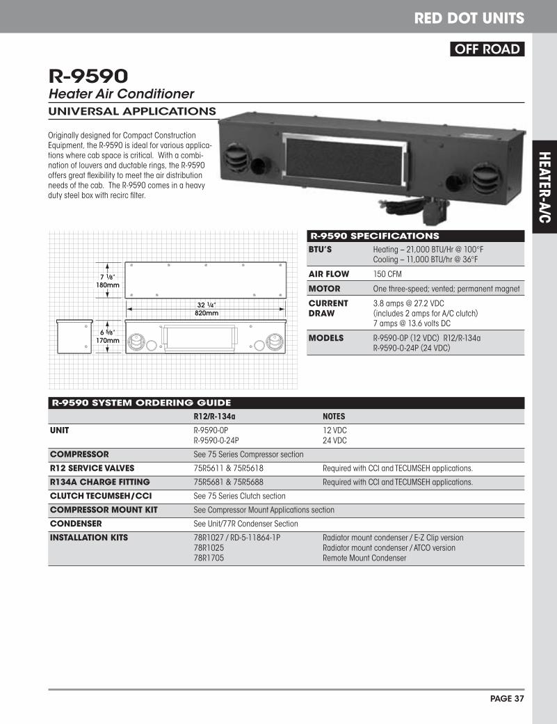
R-9590 Heater Air ConditionerUNIVERSAL APPLICATIONS
Originally designed for Compact Construction Equipment, the R-9590 is ideal for various applica-tions where cab space is critical. With a combi-nation of louvers and ductable rings, the R-9590 offers great flexibility to meet the air distribution needs of the cab. The R-9590 comes in a heavy duty steel box with recirc filter.
OFF ROAD
R-9590 SYSTEM ORDERINg gUIDE
R12/R-134a NOTES
UNIT R-9590-0P 12 VDC R-9590-0-24P 24 VDC
COMPRESSOR See 75 Series Compressor section
R12 SERvICE vAlvES 75R5611 & 75R5618 Required with CCI and TECUMSEH applications.
R134A ChARgE FITTINg 75R5681 & 75R5688 Required with CCI and TECUMSEH applications.
ClUTCh TECUMSEh/CCI See 75 Series Clutch section
COMPRESSOR MOUNT KIT See Compressor Mount Applications section
CONDENSER See Unit/77R Condenser Section
INSTAllATION KITS 78R1027 / RD-5-11864-1P Radiator mount condenser / E-Z Clip version 78R1025 Radiator mount condenser / ATCO version 78R1705 Remote Mount Condenser
R-9590 SPECIFICATIONSBTU’S Heating – 21,000 BTU/Hr @ 100°F Cooling – 11,000 BTU/hr @ 36°F
AIR FlOw 150 CFM
MOTOR One three-speed; vented; permanent magnet
CURRENT 3.8 amps @ 27.2 VDC DRAw (includes 2 amps for A/C clutch) 7 amps @ 13.6 volts DC
MODElS R-9590-0P (12 VDC) R12/R-134a R-9590-0-24P (24 VDC)

HE
ATER
-A/C
PAGE 40
RED DOT UNITS
OPTIONS:
Low profile ceiling plenum blends with any interior.
Stiffener Brackets RD-3-5790-0P
Vertical: 78R5110 10 1⁄4” dia. x 23 3⁄4” long (26.04cm x 450.33cm)
In-line Booster Pressurizer: 73R9202 (12 VDC) 73R9204 (24 VDC) For use w/Remote Mount Filters 78R5100 & 78R5110 only
30.3"768mm
24.6"624mm
12.6"320mm
10.1"257mm
10.4"264mm
3"76mm
OFF ROAD
Remote Mount Filters Must be used with In-line Booster Pressurizer Horizontal: 78R5100 10 1⁄4” dia. x 18” long (26.04cm x 45.27cm)
The R-9727 has set the standard in the off highway market for rooftop air conditioning. Years of development have made this unit the most rugged, dependable and serviceable unit in the industry.
It’s heavy gauge steel construction and heavy duty components assure trouble free operation in the most extreme environments. Should service be necessary, rubber hood tie-downs unlatch and expose easily removable components to minimize expensive down time.
NOT SHOWNWinter Cover RD-5-4031-0Backpack Filter 78R5000
3” defrost hose sold separately78R0300
R-9727 ROOFTOPAir Conditioner UnitCONSTRUCTION • MINING • AGRICULTURE
INlINE BOOSTER PRESSURIzERSAIR FlOw: 140 CFM (238 m3/h) with filter 230 CFM (391 m3/h) free flow
wEIghT: 7 lbs. (3 Kg)
MOTOR: one 12 VDC, single speed (24 VDC available)
CURRENT 10.2 amps @ 13.6 VDC or Draw: 6 amps @ 27.2 VDC
INlET/OUTlET 4” inlet, 3” outlet Size:
Gideon Technology Powered HVAC Air Filtration System12 volt Horizontal: 78R5602 RD-5-11851-0P Vertical: 78R5612 RD-5-11853-0P24 volt Horizontal: 78R5604 RD-5-11852-0P Vertical: 78R5614 RD-5-11854-0PReplacment Filter: 78R5259 RD-5-11855-0P

HEATER-A/C
PAGE 41
RED DOT UNITS
R-9727 SPECIFICATIONSBTU'S Cooling – 22,000 BTU/Hr with 36°F (6.4 kw w/2.2°C) refrigerant temp. and 80°F (26.7°C) wet bulb entering air
AIR FlOw Evaporator – 320 CFM (544 m3/h) Condenser – 850 CFM (1444 m3/h)
wEIghT 104 Lbs (47 Kg)
MOTORS Evaporator – One, 12 VDC, three-speed, 24 VDC available Condenser – One, 12 VDC, single-speed, 24 VDC available
CURRENT 29 amps @ 13.6 VDC (includes 4 amps for A/C clutch) DRAw 15 amps @ 27.2 VDC (includes 2 amps for A/C clutch)
CONTROlS Three speed blower and adjustable thermostat
MODElS R-9727-1P (12 VDC), R-9727-1-24P (24 VDC)
R-9727 SYSTEM ORDERINg gUIDE
R12/R-134a NOTES
UNIT R-9727-1P 12 VDC R-9727-1-24P 24 VDC
CONDENSER Contained in R-9727 Unit
INSTAllATION KIT 78R1605 Refrigerant hose and fittings
COMPRESSOR See 75 Series Compressor section
R12 SERvICE vAlvES 75R5611 & 75R5618 Required with CCI and TECUMSEH appliacations.
R134A ChARgE FITTINg 75R5681 & 75R5688 Required with CCI and TECUMSEH appliacations.
ClUTCh See 75 Series Clutch section
COMPRESSOR MOUNT KIT See Compressor Mount Applications section
OPTIONS Winter Cover RD-5-4031-0P Stiffener Brackets RD-3-5790-0P Backpack Filter 78R5000 Remote Mount Filters ** 78R5100 (Horizontal) 78R5110 (Vertical) Replacement Filters 78R5200 (Backpack) 78R5210 (Remote Mount) Replacement Gasket Kit RD-2-0961-0P Replacement Recirc. Filter 78R5300 Pressurizer Inlet Cap RD-5-6423-0P In-Line Booster Pressurizers * 73R9202 (12 VDC) For use with Remote Mount Filters 73R9204 (24 VDC) Replacement Receiver Drier 74R2536 * Booster Pressurizer Can Only Be Used With Remote Mount Filters ** Must be used with In-line Booster Pressurizer

HEATER-A/C
PAGE U-45
RED DOT UNITS
R-9727 SPECIFICATIONSBTU'S Cooling – 22,000 BTU/Hr with 36°F (6.4 kw w/2.2°C) re frig er ant temp. and 80°F (26.7°C) wet bulb entering air
AIR FLOW Evaporator – 320 CFM (544 m3/h) Condenser – 850 CFM (1444 m3/h)
WEIGHT 104 Lbs (47 Kg)
MOTORS Evaporator – One, 12 VDC, three-speed, 24 VDC available Condenser – One, 12 VDC, single-speed, 24 VDC available
CURRENT 29 amps @ 13.6 VDC (includes 4 amps for A/C clutch) DRAW 15 amps @ 27.2 VDC (includes 2 amps for A/C clutch)
CONTROLS Three speed blower and adjustable thermostat
MODELS R-9727-1P (12 VDC), R-9727-1-24P (24 VDC)
R-9727 SYSTEM ORDERING GUIDE
R12/R-134a NOTES
UNIT R-9727-1P 12 VDC R-9727-1-24P 24 VDC
CONDENSER Contained in R-9727 Unit
INSTALLATION KIT 78R1605 Refrigerant hose and fi ttings
COMPRESSOR See 75 Series Compressor section
R12 SERVICE VALVES 75R5611 & 75R5618 Required with CCI and TECUMSEH appliacations.
R134A CHARGE FITTING 75R5681 & 75R5688 Required with CCI and TECUMSEH appliacations.
CLUTCH See 75 Series Clutch section
COMPRESSOR MOUNT KIT See Compressor Mount Applications section
OPTIONS Winter Cover RD-5-4031-0P Stiffener Brackets RD-3-5790-0P Backpack Filter 78R5000 Remote Mount Filters 78R5100 (Horizontal) 78R5110 (Vertical) Replacement Filters 78R5200 (Backpack) 78R5210 (Remote Mount) Replacement Gasket Kit RD-2-0961-0P Replacement Recirc. Filter 78R5300 Pressurizer Inlet Cap RD-5-6423-0P In-Line Booster Pressurizers * 73R9202 (12 VDC) For use with Remote Mount Filters 73R9204 (24 VDC) Replacement Receiver Drier 74R2536
* Booster Pressurizer Can Only Be Used With Remote Mount Filters


Red Dot Corporation P.O. Box 88790, Seattle, WA 98138 (425) 251-6897 Fax (425) 251-3934
RD-2-1325-0 REV - Subject to change without notice Page 1 of 5
Model R-9727Rooftop
Air Conditioners
(FOR NEGATIVE GROUND ELECTRICAL SYSTEMS, POSITIVE GROUND SEE SECTION D)
NOTE:1. A compressor, bracket, belts and refrigeration hoses are required to complete the installation. These items may be
obtained from your RED DOT Distributor.2. The compressor must have sufficient capacity to allow the unit to deliver the rated BTU output. A 10 cubic inch
compressor (Tecumseh HG1000, Sankyo SD-510 or equiv.) turning faster than 1,750 rpm is required.3. A fresh air filter, RD-5-3905-0 is available for use in dusty environments. Replacement element for filter is Donaldson
No. P-101246 (not stocked by Red Dot).4. Galaxy hose with crimp fittings are recommended for use with R-134a systems.
A. MOUNTING THE UNIT ON CAB ROOF NOTE: Choose a mounting location for the unit that will not destroy or void warranty or effectiveness of either the Roll Over
Protection Structure or Falling Object Protection Structure.
1. Remove the headliner or loosen enough to drop the center portion. (Disregard if no headliner).2. Determine the most suitable location for mounting the air conditioning unit. (See Figure 1)
a. Mark the front-to-rear centerline of the cab on the outside of the cab roof.b. Place the mounting template on the roof using the centerline as a guide.c. Insure that air flow to the unit is not obstructed.d. Do not mount the unit with the front lower than the rear, as this will prohibit water drainage.e. Avoid cutting roof stiffeners if possible. If stiffeners are cut or roof is weakened due to the cut-out, reinforcement
may be required.3. Tape the template to the roof at the desired location. Mark the roof cut-out area (scribe the roof).4. Cut the roof where marked and drill the 3/8" dia. mounting holes. Remove burrs and sharp edges.
INSTALLATION INSTRUCTIONS
NOTE1. Please read instructions all the way through, making sure you have all the parts and tools2. While working on or around a vehicle, disconnect the battery to prevent accidental start up or electrical
shorts3. It has been established that R-12 refrigerant does deplete the earth’s protective ozone layer. Use care
so as not to release this material into the atmosphere4. A/C systems operate under high pressure At 77°F the refrigerant container Will be pressurized ,to
approximately 80 psi. Use caution When working with these materials.Goggles are recommended.
5. To function properly the A/C system must be clean and dry. Keep caps or protective covers on all hosesand fittings until final assembly
6. IMPORTANT: Attach appropriate SAE warning label to vehicle.

Red Dot Corporation P.O. Box 88790, Seattle, WA 98138 (425) 251-6897 Fax (425) 251-3934
RD-2-1325-0 REV - Subject to change without notice Page 2 of 5
ROOFTOP AIR CONDITIONER INSTALLATION SCHEMATIC CHECK INSTALLATION KIT TO MAKE CERTAIN THAT ALL PARTS LISTED ARE INCLUDED.
5. Temporarily install the headliner and trace the cut-out onto it from the roof. Remove the headliner and cut out thearea marked. Use caution and do not cut headliner opening larger than roof opening. (Check against template if indoubt.)
6. Should roof reinforcing be required, fabricate and install at this time.7. Clean the outside roof area around the cut-out and mounting holes using a mild solvent.8. Apply a thin film of adhesive 1" wide around upper surface of roof cut-out and mounting holes. Apply sealer to the
face of the sealing ring on the unit. See Figure 1.9. Set unit on cab.10. Apply sealant around bolts and nuts to prevent water leakage into cab.

Red Dot Corporation P.O. Box 88790, Seattle, WA 98138 (425) 251-6897 Fax (425) 251-3934
RD-2-1325-0 REV - Subject to change without notice Page 3 of 5
B. REFRIGERATION HOSE INSTALLATION
1. Install reusable or push on fittings on hose as shown in Figure 2. #12 suction line is recommended in place of #10for increased cooling capacity. Use step-up fitting. Be sure to clean out refrigeration hose with clean, dry air aftercuffing. Galaxy hose with crimp fittings are recommended for use with R-134a. Lubricate O-rings with mineral oil.
2. Install "0" Rings and connect hoses to fittings on unit.3. Clamp hoses within unit using clamps provided. Cut off end of mounting cap screw if it interferes with hose.4. Route hoses over the top of cab and down the back wall to the compressor. On tilt cab vehicles, route hose to the
cab pivot point and then to compressor.5. Use clamps provided to secure hoses and prevent hose movement. Hoses must not come in contact with hot
vehicle components, exhaust manifolds, etc., and they should not be subjected to mechanical abrasions. C. DRAIN HOSE INSTALLATION
1. Route the drain tubes to the unit so that they travel in a downward direction from the unit.2. Cut off the 9/16 O.D. tubes to length and connect to fittings on unit. Secure drain tubes with tie wraps. Attach to
refrigeration hoses only if they run downhill properly.3. Red Wire: Connect to an ignition switch supply through a 30 amp circuit breaker (15amp/24V).4. White Wire: Connect to compressor clutch. Route the wire around the hinge point before connecting to compressor
clutch on tilt-cab installations.
REFRIGERANT HOSE INSTALLATION MAKE CERTAIN "O" RINGS ARE ON ALL REFRIGERATION FITTINGS BEFORE SECURING

Red Dot Corporation P.O. Box 88790, Seattle, WA 98138 (425) 251-6897 Fax (425) 251-3934
RD-2-1325-0 REV - Subject to change without notice Page 4 of 5
D. WIRING
Note:a. Unit is wired for negative ground. For positive ground systems, reverse both motor leads on condenser motor and
evaporator motor.b. Unit is internally grounded.
2. Disconnect battery.3. Route red & white wire through 3/4 slot in plenum ring.4. Red Wire: Connect to an ignition switch supply through a 30 amp circuit breaker (15 amp/ 24V).5. White Wire: Connect to compressor clutch. Route the wire around the hinge point before connecting to compressor
dutch on tilt-cab installations.
E. AIR DIFFUSER PLENUM
1. Install headliner. Make sure that wire loom exits plenum ring properly and is not pinched.2. Place one foam gasket in plastic plenum assembly. If headliner is over 1 inch thick, glue tow foam gaskets together.
An extra foam gasket may be ordered (Part-RD-2-1297-0) if required.3. Place the plenum assembly up to the unit and start one 1-32 x 3" screw.4. Attach the switch-thermostat panel to the plenum with to 10-32 x 1 \2" screws.
5. Start the remaining three 10-32 x 3'1 screws.6. Tighten the four plenum assembly screws evenly until the plenum fits snugly against headliner. Make sure that
gasket does not shift out of place and electrical connectors remain attached.
ELECTRICAL SCHEMATIC

Red Dot Corporation P.O. Box 88790, Seattle, WA 98138 (425) 251-6897 Fax (425) 251-3934
RD-2-1325-0 REV - Subject to change without notice Page 5 of 5
F. FINAL ASSEMBLY AND CHECK
1. Evacuate the system, test for leaks and charge with refrigerant. The unit requires 4-6 pounds depending on hoselength.
2. Connect the battery.3. Turn the ignition switch to the "on" position, turn the thermostat to the coldest point and the fan switch to "high"
a. The clutch should click on and be engaged. If not, see Step 8.b. The condenser fan and evaporator blower should be turning at high speed.
4. Turn the fan switch to medium and low positions and check that the evaporator blower slows down.5. Turn the thermostat off and clutch should disengage.6. Start engine and run at 1500-2000 rpm. Turn unit on "full cold", "high fan". Check sight glass on receiver-drier for
bubbles, Add 6 to 8 ounces more R-12 after the sight glass just clears.7. Check thermostat to be sure clutch cycles on and off.8. If clutch does not engage the system may not have been charged to high enough pressure to actuate the Binary switch.
Place a jumper wire across the switch and run system until it is fully charged then remove jumper wire.

HE
ATER
-A/C
PAGE 44
RED DOT UNITS
28.52"
22.53
"
R-9757 ROOFTOPHeater/Air Conditioner UnitCONSTRUCTION • MINING • AGRICULTURE
Low profile ceiling plenum
blends with any interior.
OPTIONS:
Remote Mount FiltersMust be used with In-line Booster Pressurizer Horizontal: 78R5100 10 1⁄4” dia. x 18” long (26.04cm x 45.27cm)Vertical: 78R5110 10 1⁄4” dia. x 23 3⁄4” long (26.04cm x 50.33cm)In-line Booster Pressurizers 73R9202 (12 VDC) 73R9204 (24 VDC) For use with Remote Mount Filters 78R5100 & 78R5110 only
3” Defrost Hose Sold Separately 78R0300
33.7"857mm
25.9"657mm
11.8"300mm
7.5"190mm
7.5"190mm
17.0"430mm
2.5"80mm
4.0"100mm
RecirculatingAir Cutout
Air OutletCutouts
The R-9757 rooftop heater/air conditioner is designed with versatility and dependability in mind. In addition, this unit comes with HEAT. Dependable, Red Dot has again used its many years of off road experience in designing the R-9757 with the most rugged and highest quality components available.
OFF ROAD
INlINE BOOSTER PRESSURIzERSAIR FlOw: 140 CFM (238 m3/h) with filter 230 CFM (391 m3/h) free flow
wEIghT: 7 lbs. (3 Kg)
MOTOR: one 12 VDC, single speed (24 VDC available)
CURRENT 10.2 amps @ 13.6 VDC or Draw: 6 amps @ 27.2 VDC
INlET/OUTlET 4” inlet, 3” outlet Size:
Fresh Air Filter Box
RD-3-6767-1P
Gideon Technology Powered HVAC Air Filtration System12 volt Horizontal: 78R5602 RD-5-11851-0P Vertical: 78R5612 RD-5-11853-0P24 volt Horizontal: 78R5604 RD-5-11852-0P Vertical: 78R5614 RD-5-11854-0PReplacment Filter: 78R5259 RD-5-11855-0P

HEATER-A/C
PAGE 45
RED DOT UNITS
R-9757 SPECIFICATIONSBTU’S Heating – 45,000 BTU/Hr @ 100°F (13.2 kw @ 37.8°C) air temp. rise Cooling – 25,000 BTU/Hr with 36°F (7.3 kw with 2.2°C) refrigerant temp. and 80°F (26.7°C) wet bulb entering air
AIR FlOw 400 CFM (680 m3/h)
wEIghT 135 lbs. (61kg)
MOTORS Evaporator – One 12 VDC, three speed (24 VDC available) Condenser – One 12 VDC low profile (24 VDC available)
CURRENT 38.2 amps @ 13.6 VDC (includes 4 amps for A/C clutch) DRAw 19.1 amps @ 27.2 VDC (includes 2 amps for A/C clutch)
MODElS R-9757-0P (12 VDC) R-9757-0-24P (24 VDC)
R-9757 SYSTEM ORDERINg gUIDE
R12/R-134a NOTES
UNIT R-9757-0P 12 VDC - Heater A/C R-9757-0-24P 24 VDC - Heater A/C
CONDENSER Contained in the R-9757
INSTAllATION KIT 78R1805 Refrigerant hose, fittings and hardware.
COMPRESSOR See 75 Series Compressor section
R12 SERvICE vAlvES 75R5611 & 75R5618 Required with CCI and TECUMSEH appliacations.
R134A ChARgE FITTINg 75R5681 & 75R5688 Required with CCI and TECUMSEH appliacations.
ClUTCh TECUMSEh/CCI See 75 Series Clutch section
COMPRESSOR MOUNT KIT See Compressor Mount Applications section
OPTIONS Fresh Air Filter Box RD-3-6767-1P Replacement Filter RD-3-6406-0P (Fresh Air Filter Box) Paper Replacement Filter RD-3-6407-0P (Fresh Air Filter Box) Remote Mount Filters ** 78R5100 (Horizontal) 78R5110 (Vertical) Replacement Filters 78R5200 (Backpack) 78R5210 (Remote Mount) Replacement Gasket Kit RD-3-9706-0P (Gasket Kit) Replacement Recirc. Filter 78R5370 In-Line Booster Pressurizers * 73R9202 (12 VDC) For use with Remote Mount Filters 73R9204 (24 VDC) Replacement Receiver Drier 74R2546 * Booster Pressurizer Can Only Be Used With Remote Mount Filters ** Must be used with In-line Booster Pressurizer

Red Dot Corporation PO Box 88790, Seattle, WA 98138 (425) 251-6897 Fax (425) 251-3934
RD-3-9105-0 REV - For Reference Only. Subject to change without notice Page 1 of 2
Rooftop Heater – A/CModel R-9757 Series
R-134a Compatible
SERVICE PARTS LIST

Red Dot Corporation PO Box 88790, Seattle, WA 98138 (425) 251-6897 Fax (425) 251-3934
RD-3-9105-0 REV - For Reference Only. Subject to change without notice Page 2 of 2
ITEM NOTE PART NO. DESCRIPTION CAT. NO. ITEM NOTE PART NO. DESCRIPTION CAT. NO.
1 RD-3-9093-0 HOUSING ASSY 31 RD-4366-0 COOLANT TUBE 5/8" ELBOW (2) 70R71502 A RD-3-9210-0 COVER ASSY 32 RD-5-6833-0 HIGH PRESSURE SWITCH 71R61203 B RD-3-7383-0 BLOWER / MOTOR ASSY (12V) 33 RD-3-9212-0 PLUMBING COVER ASSY4 B RD-3-7383-1 BLOWER / MOTOR ASSY (24V) 34 RD-3-6624-0 ELECTRICAL PANEL ASSY5 RD-5-5049-1 MOTOR (12V) 73R4422 35 RD-5-3647-0 RESISTOR 71R14506 RD-5-5049-2 MOTOR (24V) 73R4424 36 RD-3-4812-2 PLATE - RING ASSY7 RD-3-7382-0 BLOWER HOUSING - LEFT 37 RD-4-5445-2 CONDENSER SUPPORT ASSY8 RD-3-7382-1 BLOWER HOUSING - RIGHT 38 RD-4-5441-2 CONDENSER PLATE ASSY9 RD-5-8092-0 BLOWER WHEEL - CW 73R7200 39 RD-3-4351-0 RESISTOR GUARD10 RD-5-8092-1 BLOWER WHEEL - CCW 73R7210 40 RD-3-4814-3 PLATE - FRESH AIR11 RD-3-7376-0 ENTRY RING (2) 41 RD-3-6960-0 GASKET - FRESH AIR PLATE12 RD-3-3174-0 RETAINER - MOTOR 42 A RD-5-4531-24 THERMOSTAT (PART OF # 34) 71R320013 RD-4-5444-0 CONDENSER HOUSING ASSY 43 A RD-5-6690-0 RELAY 12V 71R190214 RD-4-4724-0 CONDENSER ASSY 77R0660 44 A RD-5-6917-2 CABLE CONTROL WATER VALVE15 RD-4-4694-0 CONDENSER SCREEN 45 A RD-5-5928-0 CONTROL KNOB 71R404016 C RD-5-8747-4 FAN / MOTOR ASSY - 12VDC 46 A RD-5-6395-1 LOW PRESSURE SWITCH - LOW SIDE 71R604517 C RD-5-8747-5 FAN / MOTOR ASSY - 24VDC 47 A RD-3-6475-0 PLASTIC PLENUM18 RD-5-8790-1 GUARD - FAN ASSY 48 A RD-4123-2 SWITCH - MODE (ON-OFF-ON) 71R020019 RD-4-4520-4 SIDE BAR SUPPORT - LEFT 49 A RD-5-0071-0 SWITCH - FAN (ON-ON-ON) 71R040020 RD-4-4520-5 SIDE BAR SUPPORT - RIGHT 50 A RD-5-7192-0 CIRCUIT BREAKER - 35AMP (12V) 71R133021 RD-2-2791-0 EVAPORATOR ASSY 76R6015 51 A RD-5-67814-0 CIRCUIT BREAKER - 20AMP (24V) 71R131522 RD-1-1379-0 HEATER CORE ASSY 76R1860 52 A RD-5-3846-0 LOUVER - 4.5" DIAMETER 72R320023 RD-5-6868-0 EXPANSION VALVE 71R8300 53 A RD-3-6408-0 FILTER - RECIRCULATING AIR 78R537024 RD-5-7272-0 RECEIVER DRIER ASSY 74R2546 54 A RD-5-6693-0 RELAY (24V) 71R190425 RD-3-9099-0 TUBE ASSY - NO. 6 DRIER 55 A DX-3-9095-0 WIRE HARNESS ASSY - UNIT (12V)26 RD-3-9096-1 TUBE ASSY - NO. 6 56 A DRD-3-9095-1 WIRE HARNESS ASSY - UNIT (24V)27 RD-3-9097-0 TUBE ASSY - NO. 6 57 A RD-3-6613-0 WIRE HARNESS ASSY - PLENUM28 RD-3-9101-1 TUBE ASSY - NO. 8 58 RD-5-8086-0 RETAINER ASSY29 RD-2-2156-0 REFRIG TUBE ASSY #10 O-RING 59 RD-3-6615-2 BRACKET - FITTING ASSY
30 RD-5-7760-1 WATER VALVE ASSY 72R5220 NOTES: A = NOT SHOWN B = INCLUDES MOTOR, BLOWER ASSY,BLOWER WHEELS AND ENTRY RINGS C = 12" DIAMETER

RD-3-9094 REV -

Red Dot Corporation P.O. Box 88790, Seattle, WA 98138 (425) 251-6897 Fax (425) 251-3934
RD-3-9098-0 REV A For Reference Only. Subject to change without notice Page 1 of 4
RooftopHeater/Air Conditioner
Model R-9757
BEFORE STARTING
1. A compressor, compressor bracket, belts and refrigerant hoses are required to complete the installation.These items may be obtained from your RED DOT Distributor.
2. The compressor must have sufficient capacity to allow the unit to deliver the rated BTU output. A 8 cubicinch compressor turning faster than 1,750 rpm is required.
3. A fresh air filter, 78R 5000 is available for use in dusty environments. Replacement element for filter is78R 5200. For pressurizing the cab and drawing fresh air, 78R 5110 remote mount filter is alsoavailable with booster blower (73R 9202 - 12V or 73R 9204 - 24V).
MOUNTING THE UNIT ON CAB ROOF
1. Connect drain hose assembly as provided in theinstallation kit (RD-3-7142) to the unit.(See Figure 1)
2. Determine the location for mounting the airconditioner unit per Red Dot template.a. Refer to Figure 2b. Mark the front-to-rear centerline of the
cab on the outside of the cab roof.c. Place the mounting template on the roof
using the centerline as a guide.
INSTALLATION INSTRUCTIONS
NOTE:1. Please read instructions all the way through, making sure you have all the parts and tools 2. While working on or around a vehicle, disconnect the battery to prevent accidental start-up or electrical
shorts 3. It has been established that R-12 refrigerant does deplete the earth’s protective ozone layer Use care so as not to release this material into the atmosphere 4. A/C systems operate under high pressure. At 77°F the R-134A container will be pressurized to
approximately 80 psi. Use caution when working with these materials. Goggles are recommended 5. To function properly the A/C system must be clean and dry. Keep caps or protective covers on all hoses
and fittings until final assembly.
DRAIN HOSE INSTALLATION Figure 1

Red Dot Corporation P.O. Box 88790, Seattle, WA 98138 (425) 251-6897 Fax (425) 251-3934
RD-3-9098-0 REV A For Reference Only. Subject to change without notice Page 2 of 4
d. Ensure that air flow to the unit is not obstructed.e. Do not mount the unit with the front lower than the rear, as this will prohibit water drainage.f. Avoid cutting roof stiffeners if possible. If stiffeners are cut or roof is weakened due to
the cutout, reinforcement may be required. 3. Tape the template to the roof at the desired location. Mark the roof cut-out area (scribe the root). 4. Cut the roof where marked and drill the 1/2" dia. mounting holes. Remove burrs and sharp edges. 5. Clean the outside roof area around the cut-out and mounting holes using a mild solvent. 6. Apply a bead of sealant around upper surface of roof cut-out and mounting holes. Completely fill
bolt holes with silicone to ensure proper sealing. Also, place rubber washers on all mounting holesto prevent water leakage into the cab. See Figure 2.
7. Set unit on cab. 8. Apply sealant around bolts and nuts to prevent water leakage into cab. 9. Place the reinforcing stiffeners from inside of cab against mount holes and install six bolts. Then
install 4 condenser mount bolts. NOTE: Apply adhesive sealant to the mounting hole locations as needed. REFRIGERANT HOSE INSTALLATION
1. Cut hose to proper length. Make cut at right angles to centerline of hose. Blow cut hose with cleandry air after cutting to insure no foreign particles are left in hose. Install the appropriate steel beadlock filling on the end of the hose and crimp fitting using crimper
No. 79R 1510. A #12 suction line is recommended in place of the #10 for increased cooling
capacity. Use a step up fitting to accomplish this. 2. Use 70R 4692S Fitting #10-12 (with a schrader port) on the suction line. Place low side pressure
switch (71R 6045) on #10 -#12 Ftg (w/Schrader port) near unit under plumbing cover. 3. Route hoses over the top of cab and down the back wall to the compressor. On tilt cab vehicles,
route hose to the cab pivot and then to compressor. 4. Use clamps provided to secure hoses and prevent hose movement. Hoses must not come in contact
with hot vehicle components, exhaust manifolds, etc., and they should not be subjected tomechanical abrasions.
SECURE DRAIN HOSE
1. Secure drain tube with tie wraps. Attach to refrigerant hoses only if they run downhill properly.NOTE: Be cautious not to over-tighten tie wraps. Otherwise the drainage may be restricted.
2. Inspect to make sure that drain tubes are not kinked, especially at back of cab.
WIRING NOTE: a. Unit is wired for negative ground. For positive ground systems, reverse both motor
leads on condenser motor and evaporator motor.b. Unit is internally grounded.
1. Disconnect battery. 2. Connect plenum/control panel assembly to unit connectors.

Red Dot Corporation P.O. Box 88790, Seattle, WA 98138 (425) 251-6897 Fax (425) 251-3934
RD-3-9098-0 REV A For Reference Only. Subject to change without notice Page 3 of 4
3. Red Wire: Connect to an ignition switch supply through a 35 amp circuit breaker (20 amp/24V). 4. Black/White Wire: Connect to compressor clutch. Route the wire around the hinge point before
connecting to compressor clutch on tilt-cab installations. 5. If clutch does not engage the system may not have been charged to high enough pressure to
actuate the pressure switch. Place a jumper wire across the switch to start system. 6. See Wiring Schematic provided in installation kit (RD-3-9094).
ROOFTOP AIR CONDITIONER INSTALLATIONFigure 2

Red Dot Corporation P.O. Box 88790, Seattle, WA 98138 (425) 251-6897 Fax (425) 251-3934
RD-3-9098-0 REV A For Reference Only. Subject to change without notice Page 4 of 4
AIR DIFFUSER AND RECIRC PLENUM
1. Place cable control converter through control panel CD" hole from inside of plenum) and use controlknob provided in the kit (71R 4040) to secure it against control panel. (connect control panel wiringto unit wiring).
2. Place the plenum assembly up to the unit and start one of the mount bolts. 3. Start the remaining bolts. 4. Tighten unit/plenum assembly bolts evenly until the plenum fits snugly against headliner and
reinforcement stiffeners.
FINAL ASSEMBLY AND CHECK 1. Evacuate the system, test for leaks and charge with R-134a. The unit requires 2.5 to 3.10 pounds
depending on hose lengths. If clutch does not engage the system may not have been charged tohigh enough pressure to actuate the pressure switch. Place a jumper wire across the switch to startsystem.
2. Connect the battery. 3. Turn the ignition switch to the "on" position.
a. The clutch should click on and be engaged.b. The evaporator blower should be turning at high speed.
4. Turn the fan switch to medium and low positions and check that the evaporator blower slows down. 5. Turn the fan switch to the "off" position and compressor clutch should disengage. 6. Start engine and run at 1500-2000 rpm. Turn unit on "full cold", "high fan". Check sight glass on
receiver-drier for bubbles. Add 6 to 8 ounces more refrigerant after the sight glass just clears. (R-12only) NOTE: Check gauges for normal pressures for R-134a.
7. Check thermostat to be sure clutch cycles on and off.

HE
ATER
-A/C
PAGE 46
RED DOT UNITS
OPTIONS:
R-9777 ROOFTOPHeater/Air Conditioner UnitCONSTRUCTION • MINING • AGRICULTURE
Introducing the NEW Red Dot Rooftop. Red Dot has used the latest in design techniques to produce a rugged unit, which combines Euro styling with heavy duty components that will withstand the roughest of applications. The R-9777 Heater/Air conditioner is the first in our industry to employ engineered resin technology. This Euro styling and design sets this unit far beyond the competition in appearance, durability and performance. Through Red Dots proven performance tests the R-9777 has exceeded our expectations.
ON ROAD/OFF ROAD
Component Selection and Performance• High Performance Blower• Heavy Duty Tube and Fin Evaporator• High Capacity Spring Loaded Receiver Drier• Multi flow Condenser• A Single High Performance Durable Condenser FanDesign and Styling• Unique Low Profile Housing • “Built to Survive” Engineered Resin Housing• Positive Pressure Design• Optional Outside Air Pressurization • Easy to Service ComponentsPlenum• Contoured Design• Four Multi-Direction Louvers• Easy to Operate Switches and Controls• Recirculation Air FiltrationPerformance• 45,000 BTUs Heating • 25,000 BTUs Cooling • 355 CFM Air Flow
37"940mm
30"760mm
7.9"200mm
4 1⁄2"125mm
7 3⁄4"195mm
20 1⁄2"520mm
5 1⁄8"130mm
1⁄2" Diameter
13mm(Typical)
1⁄2" Radius 13mm
(Typical)
Mounting hole locations
16 3⁄4"425mm
Gideon Technology Powered HVAC Air Filtration System12 volt Horizontal: 78R5602 RD-5-11851-0P Vertical: 78R5612 RD-5-11853-0P24 volt Horizontal: 78R5604 RD-5-11852-0P Vertical: 78R5614 RD-5-11854-0PReplacment Filter: 78R5259 RD-5-11855-0P

HEATER-A/C
PAGE 47
RED DOT UNITS
R-9777 SPECIFICATIONSBTU’S Heating – 45,000 BTU/Hr @ 100°F (13.2 kW @ 37.8°C) air temp. rise Cooling – 25,000 BTU/Hr with 36°F (7.3 kW with 2.2°C) refrigerant temp. and 80°F (26.7°C) wet bulb entering air
AIR FlOw 355 CFM (580 m3/h)
wEIghT 65 lbs.
MOTORS Evaporator – One 12 VDC, three speed (24 VDC available) Condenser – One 12 VDC low profile (24 VDC available)
CURRENT 38.2 amps @ 13.6 VDC (includes 4 amps for A/C clutch) DRAw 19.1 amps @ 27.2 VDC (includes 2 amps for A/C clutch)
MODElS R-9777-0P Heater A/C 12VDC R-9777-0-24P Heater A/C 24VDC R-9777-1P A/C Only 12VDC R-9777-1-24P A/C Only 24VDC
R-9777 SYSTEM ORDERINg gUIDE
R12/R-134a NOTES
UNIT R-9777-0P Heater A/C 12VDC R-9777-0-24P Heater A/C 24VDC R-9777-1P A/C Only 12VDC R-9777-1-24P A/C Only 24VDC
CONDENSER Contained in the R-9777
INSTAllATION KIT 78R1805 Refrigerant hose, fittings and hardware.
COMPRESSOR See 75 Series Compressor section
R12 SERvICE vAlvES 75R5611 & 75R5618 Required with CCI and TECUMSEH applications.
R134A ChARgE FITTINg 75R5681 & 75R5688 Required with CCI and TECUMSEH applications.
ClUTCh TECUMSEh/CCI See 75 Series Clutch section
COMPRESSOR MOUNT KIT See Compressor Mount Applications section
OPTIONS Remote Mount Filters ** 78R5100 (Horizontal) 78R5110 (Vertical) Replacement Filters 78R5200 (Backpack) 78R5210 (Remote Mount) Replacement Gasket Kit RD-3-10210-0P In-Line Booster Pressurizers * 73R9202 (12 VDC) For use with Remote Mount Filters 73R9204 (24 VDC) Replacement Receiver Drier 74R2546, 74R2590 * Booster Pressurizer Can Only Be Used With Remote Mount Filters ** Must be used with In-line Booster Pressurizer
Plenum Included with kit

ITEM NOTE PART NO. DESCRIPTION CAT. NO.
1 RD-3-9135-0 COVER - CONDENSER 2 RD-3-9152-1 COVER - EVAPORATOR 3 RD-3-9151-1 HOUSING 4 RD-5-9076-2 FAN/MOTOR ASSY, 12V 73R8642 5 RD-4-5378-0 CONDENSER 77R1290 6 RD-1-1755-0 HEATER CORE ASSY 76R1560 7 RD-2-3413-0 EVAPORATOR ASSY 76R5820 8 RD-5-8583-0 MOTOR BLOWER ASSY, 12V 73R5552 9 RD-5-4531-24 THERMOSTAT - SIDE & BTM MNT 71R3200 10 RD-5-7015-0 EXPANSION VALVE 71R8320 11 RD-3-9530-1 BRACKET - EXP. VALVE 12 RD-5-9577-0 PRESSURE SWITCH 13 RD-2-3418-0 TUBE - #6 REC. DRIER-COND. 14 RD-5-9419-0 RECIEVER DRIER, R134A 74R2590 15 RD-2-3419-0 TUBE - #6 CONDENSER 16 RD-4-5453-0 TUBE ASSY - INLET, COND. 17 RD-5-9224-1 WATER VALVE - CABLE OPER. 18 RD-1-1896-0 TUBE - HEATER 19 RD-2-3416-0 TUBE ASSY - OUTLET 20 RD-3-9144-0 PLACARD
21 RD-3-9405-0 LATCH - OVER CENTER ASSY 22 RD-3-9406-0 RETAINER - LATCH PIVOT 23 RD-5-9076-3 FAN/MOTOR ASSY, 24V 73R8644 24 RD-5-8583-1 MOTOR BLOWER ASSY, 24V 73R5554 25 A RD-5-5260-0-.500 SCREW - #8 PLASTITE HEX HD. 26 A RD-5-5261-0-.750 SCREW - #12 PLASTITE HEX HD. 27 A RD-3-9608-0 WIRE HARNESS ASSY 28 A RD-5-6690-0 RELAY, 12V 71R1902 29 A RD-5-6693-0 RELAY, 24V 71R1904 30 A RD-3-9137-0 WATER VALVE CONVERTER 31 A RD-3-9142-0 PLENUM - OUTLET 32 A RD-5-9053-0 LOUVER 72R3140 33 A RD-5-9833-0 SWITCH - ROTARY, 3 SPEED 71R1160 34 A RD-5-8967-0 SWITCH - ROCKER, BLACK 71R0840
35 A RD-5-8812-0 KNOB - ROTARY CONTROL 36 A RD-3-9136-0 HOUSING - FILTER, PLENUM 37 A RD-5-9077-0 FILTER - RECIRC. 78R5410 38 A RD-3-9390-2 COVER - RECIRC. FILTER 39 A RD-5-9437-0 RESISTOR (FOR 12V) 71R1402
40 A RD-5-9445-0 RESISTOR (FOR 24V) 71R1401
Heater-Air ConditionerModel R-9777
SERVICE PARTS LIST
RD-3-9141-0 (REV A)
RED DOT CORPORATIONAftermarket Office P.O.Box 88790 Seattle, WA 98138 (425) 251-6897 fax (206) 251-3934
NOTES: A=Not Shown FOR REFERENCE ONLY. SUBJECT TO CHANGE WITHOUT NOTICE
4
9
1
23
8 24
5
67
2 1011
3
20
2122
15
1416
19 18 17
1312

Red Dot Corporation P.O. Box 88790, Seattle, WA 98138 (425) 251-6897 Fax (425) 251-3934
RD-3-9821-0 REV - For Reference Only. Subject to change without notice Page 1 of 4
INSTALLATION INSTRUCTIONS
Model R-9777Air Conditioner /
Heater
NOTE1. Please read instructions all the way through, making sure you have all the parts and tools.2. While working on or around a vehicle, disconnect the battery to prevent accidental start-up or electrical shorts.3. Use care so as not to release any R-134a refrigerant into the atmosphere.4. A/C systems operate under high pressure. At 77°F the R-134a container will be pressurized to approximately
80 psi. Use caution when working with these materials. Goggles are recommended.5. To function properly the A/C system must be clean and dry. Keep caps or protective covers on all refrigerant
hoses and fittings until final assembly.
1. A compressor, compressor bracket, belts and refrigerant hoses are required to complete the installation.These items may be obtained from your RED DOT Distributor.
2. The compressor must have sufficient capacity to allow the unit to deliver the rated BTU output. An 8 cubicinch compressor turning faster than 1,750 rpm is required.
3. For pressurizing the cab and drawing fresh air, 78R 5110 remote mount filter is available with booster blower(73R 9202-12V or 73R 9204-24V).
1. Connect drain hose and 90° elbows as provided in theinstallation kit (RD-3-9146) to the unit.(See Figure 1)
2. Determine the location for mounting the heater-airConditioner unit per Red Dot template.a. Refer to figure 2.b. Mark the front-to-rear centerline of the cab on the
outside of the cab roof.c. Place the mounting template on the roof using the
centerline as a guide.d. Ensure that air flow to the unit is not obstructed.e. Do not mount the unit with the front lower than the
rear, as this will prohibit water drainage.f. Avoid cuffing roof stiffeners if possible. If stiffeners
are cut or roof is weakened due to the cut-out,reinforcement may be required.
3. Tape the template to the roof at the desired location.Mark the roof cut-out area (scribe the roof).
NOTE: Before taping the template to the roof, decidewhat direction the unit is to be oriented. It isrecommended that the "recirc inlet" be to the rear and the"discharge air" be positioned toward the front of the cab(This puts the condenser at the front and the plumbing tothe rear).
BEFORE STARTING
MOUNTING THE UNIT ON CAB ROOF

Red Dot Corporation P.O. Box 88790, Seattle, WA 98138 (425) 251-6897 Fax (425) 251-3934
RD-3-9821-0 REV - For Reference Only. Subject to change without notice Page 2 of 4
4. Cut the rectangular inlet and outlet holes into the roof where marked (stay inside the lines). Then remove theheadliner and drill the 1/2" dia. mounting holes. Remove burrs and sharp edges. NOTE: The rectangularholes should go through the headliner, the mounting holes should not go through the headliner. If theheadliner is difficult to remove (or if the cab has no headliner), drill the 1/2" dia. mounting holes through theheadliner and use cap plug washers and cap plugs (supplied with kit) in conjunction with the M l0 mountingbolts as shown in figure 2.
5. Clean the outside roof area around the cut-out and mounting holes using a mild solvent.6. Apply a bead of sealant around upper surface of roof cut-out and mounting holes. Completely fill bolt holes
with silicone to ensure proper sealing. Also, place two rubber tapered spacers on each of the mounting holesand rotate the spacers relative to one another to level the unit on the roof (figure 2).
Red Dot Corporation P.O. Box 88790, Seattle, WA 98138 (425) 251-6897 Fax (425) 251-3934
RD-3-9821-0 REV - For Reference Only. Subject to change without notice Page 3 of 4
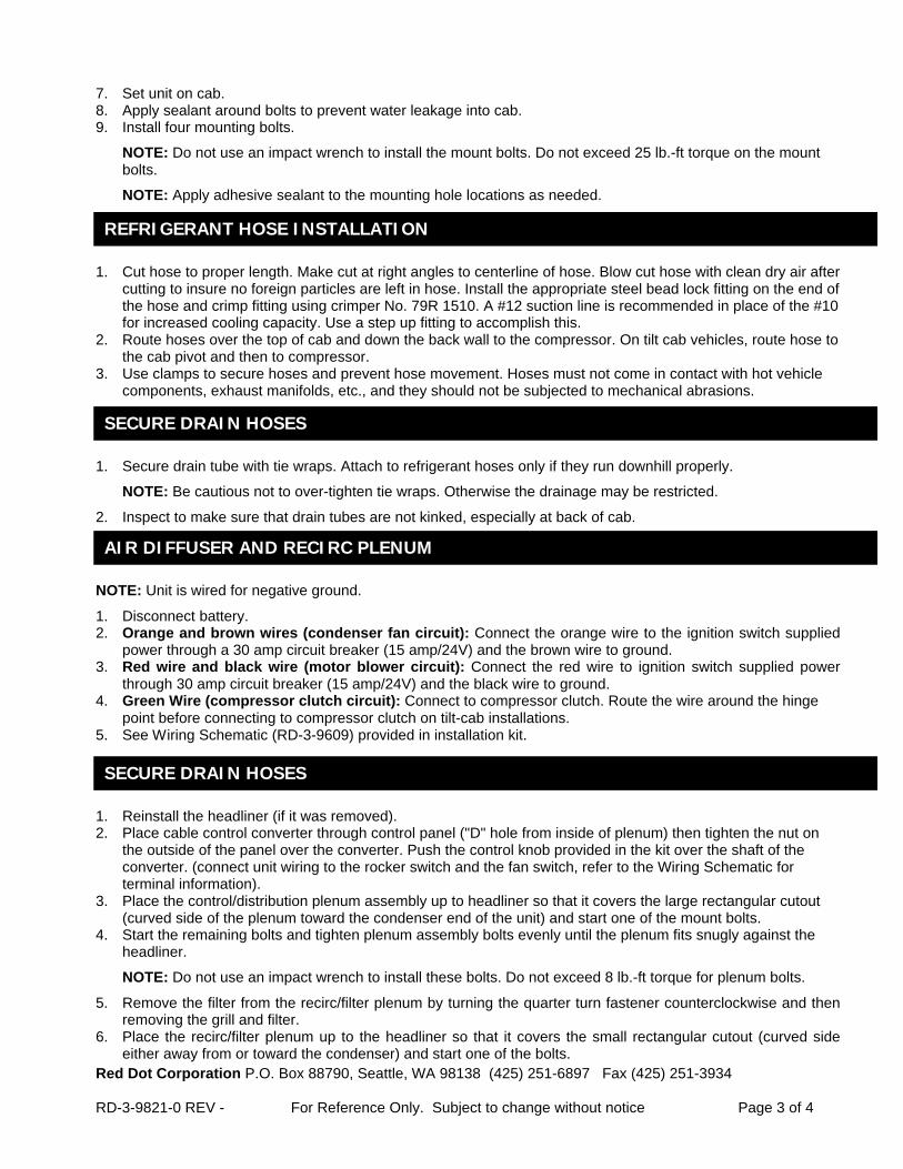
7. Set unit on cab.8. Apply sealant around bolts to prevent water leakage into cab.9. Install four mounting bolts.
NOTE: Do not use an impact wrench to install the mount bolts. Do not exceed 25 lb.-ft torque on the mountbolts.
NOTE: Apply adhesive sealant to the mounting hole locations as needed.
1. Cut hose to proper length. Make cut at right angles to centerline of hose. Blow cut hose with clean dry air aftercutting to insure no foreign particles are left in hose. Install the appropriate steel bead lock fitting on the end ofthe hose and crimp fitting using crimper No. 79R 1510. A #12 suction line is recommended in place of the #10for increased cooling capacity. Use a step up fitting to accomplish this.
2. Route hoses over the top of cab and down the back wall to the compressor. On tilt cab vehicles, route hose tothe cab pivot and then to compressor.
3. Use clamps to secure hoses and prevent hose movement. Hoses must not come in contact with hot vehiclecomponents, exhaust manifolds, etc., and they should not be subjected to mechanical abrasions.
1. Secure drain tube with tie wraps. Attach to refrigerant hoses only if they run downhill properly.
NOTE: Be cautious not to over-tighten tie wraps. Otherwise the drainage may be restricted.
2. Inspect to make sure that drain tubes are not kinked, especially at back of cab.
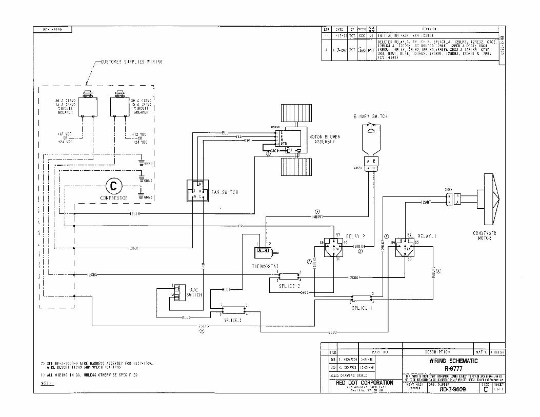
NOTE: Unit is wired for negative ground.
1. Disconnect battery.2. Orange and brown wires (condenser fan circuit): Connect the orange wire to the ignition switch supplied
power through a 30 amp circuit breaker (15 amp/24V) and the brown wire to ground.3. Red wire and black wire (motor blower circuit): Connect the red wire to ignition switch supplied power
through 30 amp circuit breaker (15 amp/24V) and the black wire to ground.4. Green Wire (compressor clutch circuit): Connect to compressor clutch. Route the wire around the hinge
point before connecting to compressor clutch on tilt-cab installations.5. See Wiring Schematic (RD-3-9609) provided in installation kit.
1. Reinstall the headliner (if it was removed).2. Place cable control converter through control panel ("D" hole from inside of plenum) then tighten the nut on
the outside of the panel over the converter. Push the control knob provided in the kit over the shaft of theconverter. (connect unit wiring to the rocker switch and the fan switch, refer to the Wiring Schematic forterminal information).
3. Place the control/distribution plenum assembly up to headliner so that it covers the large rectangular cutout(curved side of the plenum toward the condenser end of the unit) and start one of the mount bolts.
4. Start the remaining bolts and tighten plenum assembly bolts evenly until the plenum fits snugly against theheadliner.
NOTE: Do not use an impact wrench to install these bolts. Do not exceed 8 lb.-ft torque for plenum bolts.
5. Remove the filter from the recirc/filter plenum by turning the quarter turn fastener counterclockwise and thenremoving the grill and filter.
6. Place the recirc/filter plenum up to the headliner so that it covers the small rectangular cutout (curved sideeither away from or toward the condenser) and start one of the bolts.
REFRIGERANT HOSE INSTALLATION
SECURE DRAIN HOSES
AIR DIFFUSER AND RECIRC PLENUM
SECURE DRAIN HOSES

Red Dot Corporation P.O. Box 88790, Seattle, WA 98138 (425) 251-6897 Fax (425) 251-3934
RD-3-9821-0 REV - For Reference Only. Subject to change without notice Page 4 of 4
7. Start the remaining bolts and tighten the plenum assembly bolts evenly until the plenum fits snugly against theheadliner.
NOTE: Do not use an impact wrench to install these bolts. Do not exceed 8 lb.-ft torque for plenum bolts.
8. Replace the recirc filter and grill into the recirc/filter plenum.
1. Evacuate the system, test for leaks and charge with R-134a. The unit requires 3.2 to 3.4 pounds dependingon hose lengths.
2. Connect the battery.3. Turn the ignition switch to the "on" position, turn the blower switch to the high speed position, flip the a/c
rocker switch to the "on" position:a. The a/c clutch should click on and be engaged.b. The evaporator blower should be turning at high speed.c. The condenser blower should be turning.
4. Turn the fan switch to medium and low positions and check that the evaporator blower slows down.5. Turn the fan switch to the "off" position and compressor clutch should disengage.6. Start engine and run at 1500-2000 rpm. Turn unit on "full cold", "high fan". Check gauges for normal
pressures for R-134a.
FINAL ASSEMBLY AND CHECK

HE
ATER
-A/C
PAGE 48
RED DOT UNITS
R-9800 ROOFTOP or SIDE MOUNTHeater/Air Conditioner UnitCONSTRUCTION • MINING • AGRICULTURE
OPTIONS:
21.7"551mm
16.0"406mm
24.4"616mm
8.4"214mm
26.1"663mm
9.1"231mm
The R-9800 can be mounted in either VERTICAL or HORIZONTAL positions and the control panel can be remote mounted for operator convenience. Rubber tie-downs unlatch for easy servicing of all components. Optional equipment includes: a remote mount filter and in-line booster blower for a pressurized, cool, and dust free cab.
OFF ROAD
Gideon Technology Powered HVAC Air Filtration System12 volt Horizontal: 78R5602 RD-5-11851-0P Vertical: 78R5612 RD-5-11853-0P24 volt Horizontal: 78R5604 RD-5-11852-0P Vertical: 78R5614 RD-5-11854-0PReplacment Filter: 78R5259 RD-5-11855-0P
Vertical: 78R5110 10 1⁄4” dia. x 23 3⁄4” long (26.04cm x 450.33cm)
Remote Mount Filters Must be used with In-line Booster Pressurizer Horizontal: 78R5100 10 1⁄4” dia. x 18” long (26.04cm x 45.27cm)

HEATER-A/C
PAGE 49
RED DOT UNITS
Air Outlet Adapter For Pressurization72R4531
R-9800 SPECIFICATIONSBTU’S Heating – 45,000 BTU/Hr @ 100°F (13.2 kW @ 37.8°C) air temperature rise Cooling – 25,000 BTU/Hr with 36°F (7.3 kW @ 2.2°C) refrigerant temp and 80°F (26.7°C) wet bulb entering air
AIR FlOw 400 CFM (680 m3/h)
wEIghT 70 lbs. (32 kg)
MOTORS One 12 VDC, three-speed (24 VDC available)
CURRENT 22.7 amps @ 13.6 VDC (includes 4 amps for A/C clutch) DRAw 11.4 amps @ 27.2 VDC (includes 2 amps for A/C clutch)
MODElS R-9800-0P (12 VDC) R-9800-0-24P (24 VDC)
R-9800 SYSTEM ORDERINg gUIDE
R12/R-134a NOTES
UNIT R-9800-0 12 VDC R-9800-0-24 24 VDC
CONDENSER 77R0700 Radiator Mount See 77 Series Condenser section R-9725 Remote Mount See Units Condenser section
INSTAllATION KIT 78R1705 Regrigerant hose, fittings and hardware
COMPRESSOR See 75 Series Compressor section
R12 SERvICE vAlvES 75R5611 & 75R5618 Required with CCI and TECUMSEH application.
R134A ChARgE FITTINg 75R5681 & 75R5688 Required with CCI and TECUMSEH application.
ClUTCh TECUMSEh/CCI See 75 Series Clutch section
COMPRESSOR MOUNT KIT See Compressor Mount Applications section
OPTIONS Remote Mount Filters ** 78R5100 (Horizontal) 78R5110 (Vertical) Replacement Filters 78R5200 (Backpack) 78R5210 (Remote Mount) Replacement Recirculating Filters 78R5360 Replacement Gasket Kit RD-3-10210-0P In-Line Booster Pressurizers * 73R9202 (12 VDC) For use with Remote Mount Filters 73R9204 (24 VDC) Replacement Receiver Drier 74R2546 Air Outlet Adapter for In-Line Booster Pressurizer 72R4531 * Booster Pressurizer Can Only Be Used With Remote Mount Filters ** Must be used with In-line Booster Pressurizer
In-line Booster Pressurizer: 73R9202 (12 VDC) 73R9204 (24 VDC) For use w/Remote Mount Filters 78R5100 & 78R5110 only
Replacement Filter Backpack Mount78R5200
Replacement Filter Remote Mount78R5210

Red Dot Corporation PO Box 88790, Seattle, WA 98138 (425) 251-6897 Fax (425) 251-3934
RD-5-8399-0 REV - For Reference Only. Subject to change without notice Page 1 of 1
Heater-Air Conditioner
Model R-9800SERVICE PARTS LIST
ITEM NOTE PART NO. DESCRIPTION CAT. NO ITEM NOTE PART NO. DESCRIPTION CAT. NO
1 RD-3-7801-0 HOUSING ASSY. 13 RD-3-7382-0 BLOWER ASSY.2 RD-3-7799-0 COVER ASSY. 14 RD-3-7382-1 BLOWER ASSY.3 RD-1-1480-0 HEATER CORE ASSY. 15 RD-3-4814-2 PLATE - FRESH AIR4 RD-2-2885-0 EVAPORATOR ASSY. 16 RD-3-7826-1 PANEL ASSY. - ELECTRIC5 RD-3-7820-0 DUCT ASSY. - OUTLET 17 RD-5-3647-0 RESISTOR6 RD-3-7822-0 VALVE - EXPANSION 18 RD-3-7813-O RETAINER - CORE, TOP7 RD-3-7817-0 DUCT ASSY. - INLET 19 RD-3-3174-0 RETAINER - MOTOR8 RD-5-5049-0 MOTOR ASSY. 12V 20 RD-1-1474-0 TUBE ASSY. - HEATER 90°9 RD-5-5049-24 MOTOR ASSY. 24V 21 RD-5-4531-24 THERMOSTAT
10 RD-3-7376-0 RING - ENTRY 22 RD-2-2895-0 TUBE ASSY. - EVAP. #1011 RD-5-8092-0 BLOWER WHEEL (CW) 23 RD-2-2896-0 TUBE ASSY. EVAP. #612 RD-5-8092-1 BLOWER WHEEL (CCW) 24 A RD-5-8076-0 FILTER- AIR
A. NOT SHOWN

RD-3-7879 REV -RD-3-7879 REV -