rosemount 485 annubar® flanged assembly - …/media/resources/...if the 485 annubar was ordered...
TRANSCRIPT
www.rosemount.com
¢00825-0100-4809[¤
Quick Installation Guide00825-0100-4809, Rev DBDecember 2009 Flanged 485 Annubar
Step 1: Location and Orientation
Step 2: Drill Holes into Pipe
Step 3: Assemble and Check Fit-up
Step 4: Weld Mounting Hardware
Step 5: Insert the Annubar
Step 6: Mount the Transmitter
Product Certifications
Start
End
Rosemount 485 Annubar® Flanged Assembly
0100-4809 Rev DB.fm Page 1 Wednesday, December 30, 2009 3:57 PM
Quick Installation Guide00825-0100-4809, Rev DB
December 2009Flanged 485 Annubar
0100-4809 Rev DB.fm Page 2 Wednesday, December 30, 2009 3:57 PM
© 2009 Rosemount Inc. All rights reserved. All marks property of owner. Rosemount and the Rosemount logotype are registered trademarks of Rosemount Inc.
Rosemount Inc.8200 Market BoulevardChanhassen, MN USA 55317T (US) (800) 999-9307T (Intnl) (952) 906-8888F (952) 949-7001
Emerson Process Management GmbH & Co. OHGArgelsrieder Feld 382234 WesslingGermanyT 49 (8153) 9390F49 (8153) 939172
Emerson Process Management Asia Pacific Private Limited1 Pandan CrescentSingapore 128461T (65) 6777 8211F (65) 6777 0947/65 6777 0743
Beijing Rosemount Far East Instrument Co., LimitedNo. 6 North Street, Hepingli, Dong Cheng DistrictBeijing 100013, ChinaT (86) (10) 6428 2233F (86) (10) 6422 8586
IMPORTANT NOTICE
This installation guide provides basic guidelines for Rosemount485 Annubar. It does not provide instructions for configuration, diagnostics, maintenance, service, troubleshooting, Explosion-proof, Flameproof, or Intrinsically Safe (I.S.) installations. Refer to the 485 Annubar reference manual (document number 00809-0100-4810) for more instruction. This manual is also available electronically on www.rosemount.com.
If the 485 Annubar was ordered assembled to a Rosemount 3051S transmitter, see the following Quick Installation Guide for information on configuration and hazardous locations certifications: Rosemount 3051S Series Pressure Transmitter (document number 00825-0100-4801).
If the 485 Annubar was ordered assembled to a Rosemount 3095 transmitter, see the following Quick Installation Guide for information on configuration and hazardous locations certifications: Rosemount 3095 (document number 00825-0100-4716).
WARNING
Process leaks may cause harm or result in death. To avoid process leaks, only use gaskets designed to seal with the corresponding flange and o-rings to seal process connections. Flowing medium may cause the 485 Annubar assembly to become hot and could result in burns.
CAUTION
If pipe/duct wall is less than 0.125-in. (3,2 mm) use extreme caution when installing sensor. Thin walls can deform during welding, installation or from the weight of a cantilevered flowmeter. These installations may require a fabricated outlet, saddle or external flowmeter support. Please consult factory for assistance.
2
Quick Installation Guide00825-0100-4809, Rev DBDecember 2009 Flanged 485 Annubar
0100-4809 Rev DB.fm Page 3 Wednesday, December 30, 2009 3:57 PM
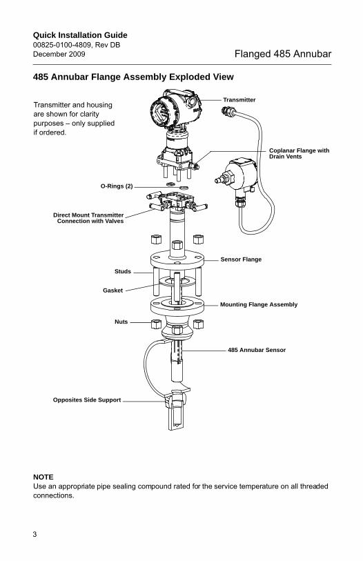
485 Annubar Flange Assembly Exploded View
NOTEUse an appropriate pipe sealing compound rated for the service temperature on all threaded connections.
Transmitter
Sensor Flange
Coplanar Flange withDrain Vents
O-Rings (2)
485 Annubar Sensor
Mounting Flange Assembly
Direct Mount TransmitterConnection with Valves
Studs
Gasket
Nuts
Opposites Side Support
Transmitter and housing are shown for clarity purposes – only supplied if ordered.
3
Quick Installation Guide00825-0100-4809, Rev DB
December 2009Flanged 485 Annubar
0100-4809 Rev DB.fm Page 4 Wednesday, December 30, 2009 3:57 PM
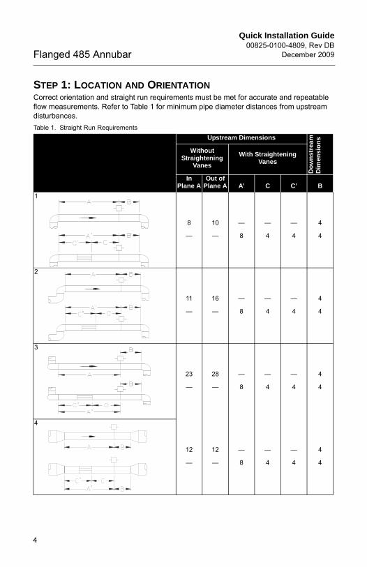
STEP 1: LOCATION AND ORIENTATIONCorrect orientation and straight run requirements must be met for accurate and repeatable flow measurements. Refer to Table 1 for minimum pipe diameter distances from upstream disturbances.Table 1. Straight Run Requirements
Upstream Dimensions
Do
wn
str
ea
mD
imen
sio
ns
Without Straightening
Vanes
With Straightening Vanes
In Plane A
Out of Plane A A’ C C’ B
1
8
—
10
—
—
8
—
4
—
4
4
4
2
11
—
16
—
—
8
—
4
—
4
4
4
3
23
—
28
—
—
8
—
4
—
4
4
4
4
12
—
12
—
—
8
—
4
—
4
4
4
4
Quick Installation Guide00825-0100-4809, Rev DBDecember 2009 Flanged 485 Annubar
0100-4809 Rev DB.fm Page 5 Wednesday, December 30, 2009 3:57 PM
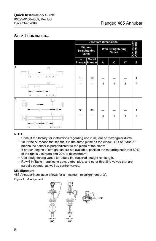
STEP 1 CONTINUED...
NOTE• Consult the factory for instructions regarding use in square or rectangular ducts.• “In Plane A” means the sensor is in the same plane as the elbow. “Out of Plane A”
means the sensor is perpendicular to the plane of the elbow.• If proper lengths of straight run are not available, position the mounting such that 80%
of the run is upstream and 20% is downstream.• Use straightening vanes to reduce the required straight run length. • Row 6 in Table 1 applies to gate, globe, plug, and other throttling valves that are
partially opened, as well as control valves.Misalignment485 Annubar installation allows for a maximum misalignment of 3°.Figure 1. Misalignment
Upstream Dimensions
Do
wn
str
eam
Dim
en
sio
ns
Without Straightening
Vanes
With Straightening Vanes
In Plane A
Out of Plane A A’ C C’ B
5
18
—
18
—
—
8
—
4
—
4
4
4
6
30
—
30
—
—
8
—
4
—
4
4
4
±3°
±3°
±3°
5
Quick Installation Guide00825-0100-4809, Rev DB
December 2009Flanged 485 Annubar
0100-4809 Rev DB.fm Page 6 Wednesday, December 30, 2009 3:57 PM
STEP 1 CONTINUED...
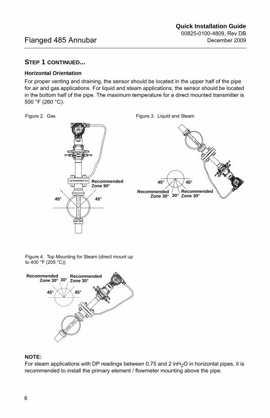
Horizontal Orientation
For proper venting and draining, the sensor should be located in the upper half of the pipe for air and gas applications. For liquid and steam applications, the sensor should be located in the bottom half of the pipe. The maximum temperature for a direct mounted transmitter is 500 °F (260 °C).
NOTE: For steam applications with DP readings between 0.75 and 2 inH2O in horizontal pipes, it is recommended to install the primary element / flowmeter mounting above the pipe.
Figure 2. Gas Figure 3. Liquid and Steam
Figure 4. Top Mounting for Steam (direct mount up to 400 °F (205 °C))
45°45°
Recommended Zone 90°
30°Recommended Zone 30°
RecommendedZone 30°
45° 45°
30°Recommended Zone 30°
RecommendedZone 30°
45° 45°
6

Quick Installation Guide00825-0100-4809, Rev DBDecember 2009 Flanged 485 Annubar
0100-4809 Rev DB.fm Page 7 Wednesday, December 30, 2009 3:57 PM
STEP 1 CONTINUED...
Vertical Orientation
The sensor can be installed in any position around the circumference of the pipe, provided the vents are positioned properly for bleeding or venting. Optimal results for liquid or steam are obtained when flow is up. For steam applications, a 90° spacer will be added to provide water legs to ensure the transmitter stays within temperature limits. The maximum temperature for a direct mounted transmitter is 500 °F (260 °C).
Figure 5. Steam Figure 6. Liquid
Figure 7. Gas
360°
Flo
w
360°
Flo
w
360°
Flo
w
7
Quick Installation Guide00825-0100-4809, Rev DB
December 2009Flanged 485 Annubar
0100-4809 Rev DB.fm Page 8 Wednesday, December 30, 2009 3:57 PM
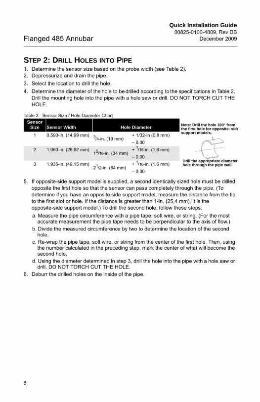
STEP 2: DRILL HOLES INTO PIPE1. Determine the sensor size based on the probe width (see Table 2).2. Depressurize and drain the pipe.3. Select the location to drill the hole. 4. Determine the diameter of the hole to be drilled according to the specifications in Table 2.
Drill the mounting hole into the pipe with a hole saw or drill. DO NOT TORCH CUT THE HOLE.
Table 2. Sensor Size / Hole Diameter Chart
5. If opposite-side support model is supplied, a second identically sized hole must be drilled opposite the first hole so that the sensor can pass completely through the pipe. (To determine if you have an opposite-side support model, measure the distance from the tip to the first slot or hole. If the distance is greater than 1-in. (25,4 mm), it is the opposite-side support model.) To drill the second hole, follow these steps:a. Measure the pipe circumference with a pipe tape, soft wire, or string. (For the most
accurate measurement the pipe tape needs to be perpendicular to the axis of flow.)b. Divide the measured circumference by two to determine the location of the second
hole.c. Re-wrap the pipe tape, soft wire, or string from the center of the first hole. Then, using
the number calculated in the preceding step, mark the center of what will become the second hole.
d. Using the diameter determined in step 3, drill the hole into the pipe with a hole saw or drill. DO NOT TORCH CUT THE HOLE.
6. Deburr the drilled holes on the inside of the pipe.
Sensor Size Sensor Width Hole Diameter
1 0.590-in. (14.99 mm) 3/4-in. (19 mm)+ 1/32-in (0,8 mm)– 0.00
2 1.060-in. (26.92 mm)15/16-in. (34 mm)
+ 1/16-in. (1,6 mm)– 0.00
3 1.935-in. (49.15 mm)21/2-in. (64 mm)
+ 1/16-in. (1,6 mm)– 0.00
Drill the appropriate diameter hole through the pipe wall.
Note: Drill the hole 180° from the first hole for opposite- sidesupport models.
8
Quick Installation Guide00825-0100-4809, Rev DBDecember 2009 Flanged 485 Annubar
0100-4809 Rev DB.fm Page 9 Wednesday, December 30, 2009 3:57 PM
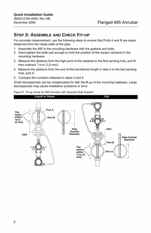
STEP 3: ASSEMBLE AND CHECK FIT-UPFor accurate measurement, use the following steps to ensure that Ports A and B are equal distances from the inside walls of the pipe.1. Assemble the 485 to the mounting hardware with the gaskets and bolts.2. Hand tighten the bolts just enough to hold the position of the sensor centered in the
mounting hardware.3. Measure the distance from the high point of the weldolet to the first sensing hole, port B,
then subtract 1/16-in (1,6 mm).4. Measure the distance from the end of the transferred length in step 4 to the last sensing
hole, port A.5. Compare the numbers obtained in steps 3 and 4.Small discrepancies can be compensated for with the fit-up of the mounting hardware. Large discrepancies may cause installation problems or error.
Figure 8. Fit-up check for 485 Annubar with Opposite-Side SupportLiquid or Steam Gas
ODF
Port B
Port A
Pipe Outside
Diameter
The same within 1/8-in. (3 mm)
The same within 1/8-in. (3 mm)
Pipe Outside Diameter
Port A
Port B
ODF
9
Quick Installation Guide00825-0100-4809, Rev DB
December 2009Flanged 485 Annubar
0100-4809 Rev DB.fm Page 10 Wednesday, December 30, 2009 3:57 PM
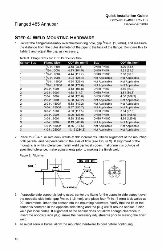
STEP 4: WELD MOUNTING HARDWARE1. Center the flanged assembly over the mounting hole, gap 1/16-in. (1,6 mm), and measure
the distance from the outer diameter of the pipe to the face of the flange. Compare this to Table 3 and adjust the gap as necessary.
Table 3. Flange Sizes and ODF Per Sensor Size
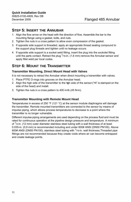
2. Place four 1/4-in. (6 mm) tack welds at 90° increments. Check alignment of the mounting both parallel and perpendicular to the axis of flow (see Figure 9). If alignment of the mounting is within tolerances, finish weld per local codes. If alignment is outside of specified tolerance, make adjustments prior to making the finish weld.
Figure 9. Alignment
3. If opposite-side support is being used, center the fitting for the opposite side support over the opposite side hole, gap 1/16-in. (1,6 mm), and place four 1/4-in. (6 mm) tack welds at 90° increments. Insert the sensor into the mounting hardware. Verify that the tip of the sensor is centered in the opposite side fitting and the plug will fit around sensor. Finish weld per local codes. If alignment of the sensor does not allow enough clearance to insert the opposite side plug, make the necessary adjustments prior to making the finish weld.
4. To avoid serious burns, allow the mounting hardware to cool before continuing.
Sensor Size Flange Size ODF (in. (mm)) Size ODF (in. (mm)
1 11/2-in. 150# 3.88 (98.5) DN40 PN16 3.09 (78.6) 1 11/2-in. 300# 4.13 (104.9) DN40 PN40 3.21 (81.6)1 11/2-in. 600# 4.44 (112.7) DN40 PN100 3.88 (98.6)1 11/2-in. 900# 4.94 (125.4) Not Applicable Not Applicable1 11/2-in. 1500# 4.94 (125.4) Not Applicable Not Applicable1 11/2-in. 2500# 6.76 (171.6) Not Applicable Not Applicable2 2.0-in. 150# 4.13 (104.8) DN50 PN16 3.40 (86.3)2 2.0-in. 300# 4.38 (111.2) DN50 PN40 3.51 (89.3)2 2.0-in. 600# 4.76 (120.8) DN50 PN100 4.30 (109.3)2 2.0-in. 900# 5.88 (149.2) Not Applicable Not Applicable2 2.0-in. 1500# 5.88 (149.2) Not Applicable Not Applicable2 3.0-in. 2500# 9.87 (250.7) Not Applicable Not Applicable3 3.0-in. 150# 4.63 (117.5) DN80 PN16 3.84 (97.6)3 3.0-in. 300# 5.00 (126.9) DN80 PN40 4.16 (105.6)3 3.0-in. 600# 5.38 (136.6) DN80 PN100 4.95 (125.6)3 4.0-in. 900# 8.19 (208.0) Not Applicable Not Applicable3 4.0-in. 1500# 8.56 (217.5) Not Applicable Not Applicable3 4.0-in. 2500# 11.19 (284.2) Not Applicable Not Applicable
ODF
Tack Welds
10
Quick Installation Guide00825-0100-4809, Rev DBDecember 2009 Flanged 485 Annubar
0100-4809 Rev DB.fm Page 11 Wednesday, December 30, 2009 3:57 PM
STEP 5: INSERT THE ANNUBAR1. Align the flow arrow on the head with the direction of flow. Assemble the bar to the
mounting flange using a gasket, bolts, and nuts.2. Tighten the nuts in a cross pattern to allow even compression of the gasket.3. If opposite side support is threaded, apply an appropriate thread sealing compound to
the support plug threads and tighten until no leakage occurs.4. If opposite side support is a socket weld fitting, insert the plug into the sockolet fitting
until the parts contact. Retract the plug 1/16-in. (1,6 mm) remove the Annubar sensor and apply fillet weld per local codes.
STEP 6: MOUNT THE TRANSMITTER
Transmitter Mounting, Direct Mount Head with ValvesIt is not necessary to retract the Annubar when direct mounting a transmitter with valves.1. Place PTFE O-rings into grooves on the Annubar head.2. Align the high side of the transmitter to the high side of the sensor (“Hi” is stamped on the
side of the head) and install.3. Tighten the nuts in a cross pattern to 400 in•lb (45 N•m).
Transmitter Mounting with Remote Mount HeadTemperatures in excess of 250 °F (121 °C) at the sensor module diaphragms will damage the transmitter. Remote mounted transmitters are connected to the sensor by means of impulse piping, which allows process temperatures to decrease to a point where the transmitter is no longer vulnerable.Different impulse piping arrangements are used depending on the process fluid and must be rated for continuous operation at the pipeline design pressure and temperature. A minimum of 1/2-in. (12 mm) outer diameter stainless steel tubing with a wall thickness of at least 0.035-in. (0,9 mm) is recommended including and under 600# ANSI (DN50 PN100). Above 600# ANSI (DN50 PN100), stainless steel tubing with 1/16-in. wall thickness.Threaded pipe fittings are not recommended because they create voids where air can become entrapped and create leakage points.
11
Quick Installation Guide00825-0100-4809, Rev DB
December 2009Flanged 485 Annubar
0100-4809 Rev DB.fm Page 12 Wednesday, December 30, 2009 3:57 PM
STEP 6 CONTINUED...
The following restrictions and recommendations apply to impulse piping location:1. Impulse piping that runs horizontally must slope at least one inch per foot (83 mm/m).
• Slope downward (toward the transmitter) for liquid and steam applications• Slope upward (toward the transmitter) for gas applications.
2. Outdoor installations for liquid, saturated gas, or steam may require insulation and heat tracing to prevent freezing.
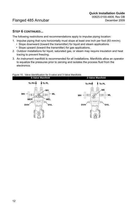
3. An instrument manifold is recommended for all installations. Manifolds allow an operator to equalize the pressures prior to zeroing and isolates the process fluid from the electronics.
Figure 10. Valve Identification for 5-valve and 3-Valve Manifolds5-Valve Manifold 3-Valve Manifold
To PH To PL
MH
MV
ML
DVLDVH
MELMEH
2
1
To PH To PL
MH
ME
ML
DVLDVH
2
1
12
Quick Installation Guide00825-0100-4809, Rev DBDecember 2009 Flanged 485 Annubar
0100-4809 Rev DB.fm Page 13 Wednesday, December 30, 2009 3:57 PM
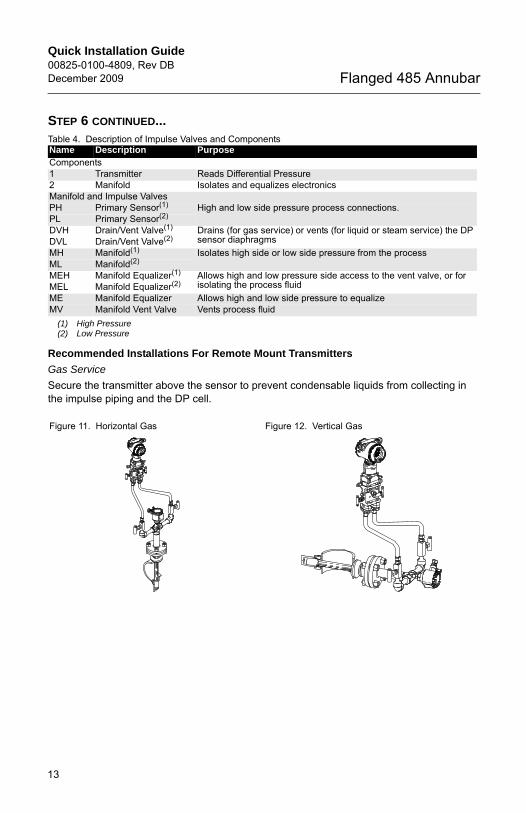
STEP 6 CONTINUED...Table 4. Description of Impulse Valves and Components
Recommended Installations For Remote Mount Transmitters
Gas Service
Secure the transmitter above the sensor to prevent condensable liquids from collecting in the impulse piping and the DP cell.
Name Description PurposeComponents1 Transmitter Reads Differential Pressure 2 Manifold Isolates and equalizes electronicsManifold and Impulse ValvesPH Primary Sensor(1)
(1) High Pressure
High and low side pressure process connections.PL Primary Sensor(2)
(2) Low Pressure
DVH Drain/Vent Valve(1) Drains (for gas service) or vents (for liquid or steam service) the DP sensor diaphragmsDVL Drain/Vent Valve(2)
MH Manifold(1) Isolates high side or low side pressure from the processML Manifold(2) MEH Manifold Equalizer(1) Allows high and low pressure side access to the vent valve, or for
isolating the process fluidMEL Manifold Equalizer(2) ME Manifold Equalizer Allows high and low side pressure to equalizeMV Manifold Vent Valve Vents process fluid
Figure 11. Horizontal Gas Figure 12. Vertical Gas
13
Quick Installation Guide00825-0100-4809, Rev DB
December 2009Flanged 485 Annubar
0100-4809 Rev DB.fm Page 14 Wednesday, December 30, 2009 3:57 PM
STEP 6 CONTINUED...
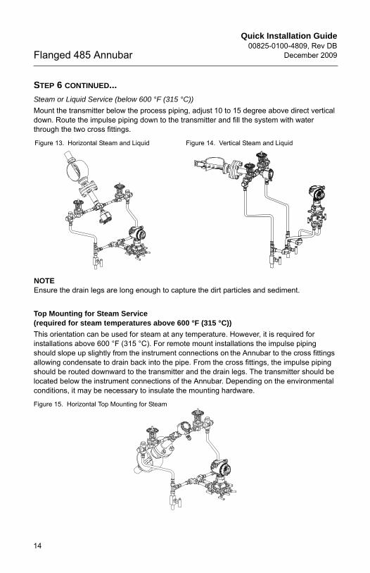
Steam or Liquid Service (below 600 °F (315 °C))
Mount the transmitter below the process piping, adjust 10 to 15 degree above direct vertical down. Route the impulse piping down to the transmitter and fill the system with water through the two cross fittings.
NOTEEnsure the drain legs are long enough to capture the dirt particles and sediment.
Top Mounting for Steam Service (required for steam temperatures above 600 °F (315 °C))
This orientation can be used for steam at any temperature. However, it is required for installations above 600 °F (315 °C). For remote mount installations the impulse piping should slope up slightly from the instrument connections on the Annubar to the cross fittings allowing condensate to drain back into the pipe. From the cross fittings, the impulse piping should be routed downward to the transmitter and the drain legs. The transmitter should be located below the instrument connections of the Annubar. Depending on the environmental conditions, it may be necessary to insulate the mounting hardware.
Figure 15. Horizontal Top Mounting for Steam
Figure 13. Horizontal Steam and Liquid Figure 14. Vertical Steam and Liquid
14

Quick Installation Guide00825-0100-4809, Rev DBDecember 2009 Flanged 485 Annubar
0100-4809 Rev DB.fm Page 15 Wednesday, December 30, 2009 3:57 PM
PRODUCT CERTIFICATIONS
Approved Manufacturing LocationsRosemount Inc. — Chanhassen, Minnesota USA
European Directive InformationThe EC declaration of conformity for all applicable European directives for this product can be found on the Rosemount website at www.rosemount.com. A hard copy may be obtained by contacting our local sales office.European Pressure Equipment Directive (PED) (97/23/EC)
Rosemount 485 Annubar — Refer to EC declaration of conformity for conformity assessmentPressure Transmitter — See appropriate Pressure Transmitter QIG
Hazardous Locations CertificationsFor information regarding the transmitter product certification, see the appropriate transmitter QIG:
• Rosemount 3051S (document number 00825-0100-4801)• Rosemount 3095M (document number 00825-0100-4716)
15

Quick Installation Guide00825-0100-4809, Rev DB
December 2009Flanged 485 Annubar
0100-4809 Rev DB.fm Page 16 Wednesday, December 30, 2009 3:57 PM
16