roxel im technology, analysis of trial results, future im ... · trial results, future im...
TRANSCRIPT

Roxel IM technology, analysis of trial results, future IM programmes in France and UK
IMEMTS – 14th May 2009Andrew Strickland, Jean-Claude Nugeyre,Raymond Coleno, Didier Zanelli

Page 2IMEMTS May 2009
Summary
1. Introduction
2. Roxel’s main IM trial results
3. Analysis of test results and key technology
• Propellants, Cases, Mitigation devices and Modelling
4. Challenges with RM IM response assessment
• Influence of test conditions
• Interpretation of test results
5. IM technology gap and new research areas
• French MOD ARP APTE programme
• UK programmes
6. IM low cost design methodology
7. Conclusion

Page 3IMEMTS May 2009
Introduction: Rocket Motor Overview
Propellant (Energetic Material)
Igniter (Mitigation Device)
Case (Pressure Vessel)
Nozzle
A Rocket Motor (RM) must deliver thrust, by expansion of hot gas generated by an Energetic Material (propellant) burning under pressure in a case (pressure vessel), through a nozzle, at any moment of its life time.
Insensitive Munition (IM) RM must minimise the probability of inadvertent initiation and the severity of subsequent collateral damage to weapon platform logistic systems and personnel when subject to an unplanned stimuli.
This requires designers to meet this complex challe nge to achieve a fully IM compliant RM able to deliver the maximum desired energy.

Page 4IMEMTS May 2009
Introduction: Roxel IM Approach
• IM response of a Rocket Motor (RM) is a critical requirement
• For over 15 yrs Roxel has developed an IM technology design approach based on: • Understanding of the behaviour of energetic materials and RM reactions under stimuli
• Modelling and calculations
• Participation of Roxel experts in international IM groups
• Database setup of more than 200 IM trials on demons trators and RM’s
Fast Heating
Slow Heating
Bullet Impact Fragment Impact
Shape Charge Jet
SympatheticReaction

Page 5IMEMTS May 2009
Acronyms• List of key acronyms within presentation
ALU AluminiumAP Ammonium PerchlorateAPTE Amelioration Propulsion TactiqueARP Advanced Research ProgrammeBI Bullet ImpactCDB Cast Double BaseCF Carbon FibreCFRP Carbon Fibre Reinforced PlasticEDB Extruded Double BaseEM Energetic MaterialEMCDB Elastomeric CDBFH Fast HeatingFI Fragment ImpactGAP Glycidil PolyazotureHBR High Burning RateHFI Heavy Fragment ImpactHTPB Hydroxy Terminated PolybutadieneHTPE Hydroxy Terminated PolyetherHVM Hyper Velocity MissileHVSG High Velocity Shot Gun
• References used in the subsequent table are used throughout the presentation to refer to corresponding trial results : [ 27 ] refers to trial result “Ref 27” in table Page 6
IM Insensitive MunitionKOA Kevlar Overwrap AluminiumLMA Low temperature Melting Alloy LTI Low Temperature IgniterMD Mitigation DeviceNG Nitro GlycerinePID Pre Ignition DevicePV Pressure VesselREF ReferenceRM Rocket MotorRRPR Reduced Range Practice RocketSCJ Shaped Charge JetSDT Shock to Detonation TransitionSH Slow HeatingSMA Shape Memory AlloySR Sympathetic ReactionSSL Steel Strip LaminateXDT Delayed Detonation TransitionXLDB Cross Linked Double Base

Page 6IMEMTS May 2009
Selection of Roxel IM Test ResultsPropellant Case M itigation Technology FH SH BI FI HFI SR SC J
V V V V III III
V V V V IV IV III
2 RM In Service EDB Alu. - V V N/R I
3 RM. Demonstrator EDB Alu. - V V V N/R <III
5 RM. Demonstrator EDB SSL PID (Pre Ignition Device) V V V
9 RM. Demonstrator EDB S1 Alu. - V IV V I
10 RM. Demonstrator EDB S2 Alu. - V IV v <III
11 RM In Service CDB KOA - IV III IV III I
12 RM In Service EDB KOA - IV IV IV V IV
13 RM In Service EMCDB SSL - V V
14 RM In Service Composite Alu. - V V
15 RM In Service CDB KOA - V V
16 RM. Demonstrator EDB KOA - V N/R
17 RM. Demonstrator XLDB 2 CRFP - V N/R
18 RM under Qualification CDB KOA - V V
19 RM under Qualification CMDB KOA - V V
20 Tech. Demonstrator Composite KOA LTI (Low Temperature Igniter) V IV
21 RM In Service EDB Steel - IV IV V I II I
22 RM. Demonstrator GAP Comp. KOA - V N/R
23 RM In Service Composite SSL LTI V IV V
24 RM In Service Composite Steel Intumescent paint V
25 RM. Demonstrator Composite Steel Membrane V
26 Tech. Demonstrator CompositeHTPE SSL - V III III
27 RM. Demonstrator CompositeHTPE SSL LTI IV II IV III IV
28 RM In Service Composite 1 Steel - III V
29 RM. Demonstrator Composite 1 Steel Membrane V
30 Tech. Demonstrator Composite 1 Steel - IV III IV III
31 Tech. Demonstrator Composite 1 Steel Weakened case IV III IV III
34 Tech. Demonstrator Composite 1 Steel Steel case + CF patches IV III
37 RM. Demonstrator Composite 2 Steel - III
38 Tech. Demonstrator Composite 2 Steel FoamA II V
39 Tech. Demonstrator Composite 2 Steel + CF - IV II IV III
40 Tech. Demonstrator Composite 2 Steel + CF Membrane, LT I V III III
42 Tech. Demonstrator Composite 2 Steel FoamA II V
45 Tech. Demonstrator XLDB 3 Steel + CF - V IV IV I
46 Tech. Demonstrator XLDB 1 Steel - V I
47 RM. Demonstrator CDB CFRP - V V V V
48 RM. Demonstrator EMCDB SSL PID, shear closure V V V V V
49 RM In Service Composite Steel - III I
50 RM. Demonstrator Composite Steel 1 Weakened case, LTI III III
51 RM. Demonstrator Composite Steel 2 Weakened case, LTI V III IV IV
52 RM In Service Composite Alu. - V IV
53 RM In Service Composite Alu. - V IV III
54 RM In Service CDB SSL - V V V
55 RM In Service composite Steel - II III
NATO STANAG 4439
FRANCE INSTRUCTION DGA 260 IPE M URAT ***
Specimen StatusTechnology Description IM Characteristic of rocket m otor (tested)
Ref.

Page 7IMEMTS May 2009
EDB, CDB, CMDB, and new XLDB & GAP propellants giv e:
• Type V or IV response for FH and SH
• Type V or IV response with adequate barrier or storage configuration for BI, FI and SR [12, 47, 48 ] but if without this configuration then Type I, II or III for FI, SR & SCJ [2, 9, 21 ] since they are more sensitive to intense shocks due to NG, explosive fillers and combustion instability suppressant content
• 1% of refractories in some EDB & CDB propellants increase the FI SDT sensitivity by 500 m/s [9,10 ]
• NG replaced by less sensitive Nitrate Ester leads to type V or No Reaction for BI [17, 22,]
Test results & key technology: Propellants
[47] Type V FH, BI, SR & FI (2530m/s): CDB no refractories
[54] Type V FH, BI & FI (2530m/s): CDB with refractories
[22] NR GAP RDX KOA
[21] Type IV BI : EDB [21] Type I SCJ, SR: EDB [17] Type V, NR: XLDB2
[21] Type IV SH : EDB [17] Type NR: XLDB2

Page 8IMEMTS May 2009
Composite HTPB propellants give:
• Type V & IV reaction for FH, BI and FI aggressions. Large motors, High Burning Rate propellant or a very
strong case can lead to Type III reactions [28,37,49,50,55 ]
• Type I or II very violent reaction to SH aggression (without any Mitigation Devices) due to AP damage & bulk propellant exothermic reaction. Promising additives (at propellant level for SH) have not been effective in
RM’s [ 38, 39, 42, 49, 55 ]
Composite HTPE propellant give:
• Type V response in SH lab tests has not been successful when tested in RM [ 26, 27 ]
Test results & key technology: Propellants
[14] Type V FH : COMP HTPB
[27] Type III & NR HFI :COMP HTPE [27] Type II SH : COMP HTPE
[14] Type V BI : COMP HTPB[49] Type I SH : COMP HTPB
[51] Type IV FI 1754 m/s : COMP HTPB

Page 9IMEMTS May 2009
Test results & key technology: CasesRM Case main function is to withstand internal pres sure during RM operation.
• Case properties have a strong influence on the level of confinement and reaction violence for FH, BI, FI aggressions when EM is ignited, and a moderate influence on RM responses for SH, SR, SCJ aggressions [ 28,
37, 49, 50 ]
• Al, SSL, KOA, CFRP cases lose mechanical properties very quickly under FH & BI aggressions and commonly lead to venting upon ignition of propellant, which is able to burn benignly at atmospheric pressure giving Type V reactions or type IV in case of propulsion, ejections or overpressure for large motor [3, 5,11,13, 23, 52, 53, 54, …] .
• Weakened steel cases with an appropriate manufacturing process and grain design, lead to case rupture prior to ignition of propellant for FH [51]
[28] Type III FH : Steel
[51] Type V FH : Weakened Steel
[23] Type V FH, BI : SSL
[19] Type V FH, BI : KOA
[52] Type V FH : ALU

Page 10IMEMTS May 2009
Test results & key technology: Mitigation devices
Several types of mitigation devices have been devel oped and tested
• Thermal barriers (Internal and/or external & membrane ) delay the reaction and potentially control the case failure mode and decrease the response to a Type V for FH aggression. [ 24, 25, 29 ]
• PID and LTI initiate EM at a temperature lower than the threshold of thermal reaction for SH aggression and can improve the RM reaction from a Type I or II to a Type III or IV [ 5, 20, 23, 27, 48, 50, 51 ].
• Foam in the inner bore of the charge to avoid SDT or XDT for BI & FI [ 38, 42 ] .
• LMA, SMA, and active venting systems have been tested at laboratory scale
2.75” SSL with PID:SH Type V (BWB / WDT91 trial photo)
[38, 42 ] Type V BI : Steel + Foam
[24] Type V FHType of foam
[ 38, 42 ] Type V BI foam in bore [5, ,20, 23, 27, 48, 50, 51] PID, LTI
Intumescent Paint expansion

Page 11IMEMTS May 2009
Test results & key technology: ModellingModelling of the IM phenomena is conducted for ther mal aggressions, but still in preliminary studies f or
mechanical aggressions
• Will highlight problematic design features and further the design of IM mitigation technology [ 19, 53 ]
• Assist in IM trial instrumentation and results analysis (reaction time, temperature state of specimen)
• Requires reliable input data, sometimes difficult to obtain in order to conduct accurate state modelling of the stimuli:
• Wind, fire, positioning within trial, clamps and fixings, mechanical characteristics, etc…
Challenging to predict the subsequent reaction effe cts
• EM state under aggression and initiation process, distance of inert and EM projections, overpressure levels, number of fragments, etc…
0
20
40
60
80
100
120
140
160
180
200
0 50 100 150 200 250
curvilinear abscissa (mm)
Temperature (°C)
0
50
100
150
200
250
300
0 50 100 150 200 250 300
temps (heures)
tem
péra
ture
(°C
)
Te=
154°
C
Te=
155°
C
Te=
160°
C
Te=
165°
C
Te=
170°
C
Te=
180°
C
Te=
190°
C
Te=
200°
C
[19] Thermal insulation design to validate ignition point SH temperature calculation
FI on a metallic case calculation
SH induction curves 150
200
250
300
350
0 25 50 75 100
rayon (mm)
tem
péra
ture
(°C
)
Te=154°C
Te=180°C
Te=190°C
Te=200°C
Short time exposure at high temperature, skin initiation
Long time exposure atlow temperature,heart initiation

Page 12IMEMTS May 2009
Synthesis of key Roxel IM technology
• Thermal threat: Fast Heat (FH) & Slow Heat (SH)
• Case technologies & venting devices to decrease and control burst effects (FH & SH)
• Thermal barriers to delay reaction and possibly give orientation to a case failure (FH)
• Pre-ignition of propellants at a temperature lower than the threshold of EM thermal
reaction (SH)
• PID or LTI combined to case venting technology could achieve the best IM response
• Modelling and simulation of thermal state in RM (FH & SH)
• Mechanical threats: Bullet Impact (BI) & Fragment I mpact (FI) Sympathetic Reaction (SR) & Shape Charge Jet (SCJ)
• Less shock sensitive propellants: low Card Gap Test and High Velocity Shotgun result (> 600m.s-1 ) and modified propellants (SH)
• Appropriate storage barriers, case technologies to absorb impact energy & increase
venting at EM reaction or disrupt effectively upon impact
• Internal barrier, foam in the inner bore of the charge
• Modelling and simulation of mechanical EM state in RM (BI & FI)

Page 13IMEMTS May 2009
Challenges with RM IM response assessment
• During last 20 years IM tests have been conducted in various test centres (SNPE, DGA / CAEPE, UK MoD, and others) and are very often subject to discussions on tests conditions and results interpretation.
• IM trials are not perfect tests, they are very costly with low repeatability
• Even if they are in accordance with STANAG and AOP, test’s centre experience, safety requirements, measurements, and of course weather conditions can induce test variabilities.
• The analysis of test results and their interpretation can be subject to discussions giving
opportunity to doubt about IM reaction type assessment

Page 14IMEMTS May 2009
Specimen positions: Distance above fire, Horizontal/Vertical, distance of donor acceptor, SR SCJ configurations
Attachments and fixings: Rigidity, dimensions of support, thrust safety devices
Influence of test conditions
986983935901812T° (°C)
7060504030Fuel distance (cm)
[ 52 ] Type V? FH SUPPORT BROKEN and
PROPELLANT EJECTION AT 15.2 M
[ 51 ] Type V FH CASE DEFORMATION IN
SUPPORTS

Page 15IMEMTS May 2009
Cell characteristics: Confinement of specimen, protection against ejection & blast pressure
Influence of test conditions
Weather conditions: Wind, temperature, rain
[ 49, 50, 51 ] SH HEAVY CELL [ 20 ] SH LIGHT CELL
SH PROTECTION CELL
[ 21 ] SH PROTECTION CELL
[ 27 ] SH PROTECTION CELL
[ 14 ] WIND EFFECT

Page 16IMEMTS May 2009
Characteristics of aggression• FH: Type & temperature of fuel (fuel, wood, gas)• HFI: Fragment material, mass & shape (spherical or parallelipedic)• BI, FI, HFI: Velocities difficult to reach accurately• BI, FI, HFI: Choice of impact position not discussed• SH: Heat rate, initial temperature (possibility of 100°C?)• SCJ: Shape charge type specified in Stanag is not available
Validity of a test non compliant with Stanag: No tes t?• Temperature and delays, velocity, impact point, heat rate, measurements insufficient or not available• A clear IM response (I to V) is not really possible for SR : the expected result is “Transmission or No
Transmission of Detonation”. For example it does not seem possible to justify a Type V or IV reaction
Influence of test conditions
température du feu
0
200
400
600
800
1000
1200
0 100 200 300 400 500 600
temps (s)
tem
péra
rture
(°C
)
T1T2T3T4Tstandard
Measurement difficulties (blast pressure and video) for SH
ALTERNATIVE BLAST PRESSURE MEASUREMENT METHOD “CHALARD BOX”
TEMPERATURES NOT COMPLIANT
IMPACT NOT COMPLIANT
FH FUEL AND GAS AGGRESSION

Page 17IMEMTS May 2009
STANAG 4439 edition 2 and AOP-39 edition 2 give definitions, threats, IM requirements, test procedures and guidance for interpretation of responses
-Heat flow < 4 KW/m 2
at 15 m
-Debris remains in place, except covers-No fragment of more than 79J or more than
150g beyond 15m
-Energetic materials remain nearby
(< 15 m)
-Blast effect limited to∆∆∆∆P < 50 mbar at 5 m
-Split in a non-violent way
-Smooth release of gases
-Separation of ends
-CombustionV
-Damage caused by heat and smoke-Propulsion of
unattached sample
-Expulsion of end caps and large structural
parts-No significant
damage
-Scattering of materials
-Risk of fire
-Blast effect limited to∆∆∆∆P < 50 mbar at 15 m
-Breaks but does not fragment into more
than 3 parts-Expulsion of end caps
-Gases release through opening
-Combustion/Deflagration-Non-violent pressure
releaseIV
-Small craters in the ground
-Long range projection-Damage to metal
plates (breaks, rips, cuts)
-Scattering of burning materials
-Risk of fire
-Blast effect< detonation-Damage to
neighbouring structures
-∆∆∆∆P > 50 mbar at 15 m
-Violent breaking into large fragments
-Fast combustion of confined material
(Explosion)-Local pressure build up
III
-Ditto-Proportional to % of detonating material
-Ditto-Ditto-Ditto-Partial fragmentation
+large fragments
-Partial detonationII
-Large craters in the ground.
-Perforation, plastic deformation or
fragmentation of adjacent metal plates.
-All the materials react
-Intense shock wave-Damage to
neighbouring structures
-Very fast plastic deformation
-Total fragmentation
-Detonation-Supersonic
decomposition reaction
I
OTHERPROJECTION OF
FRAGMENTS
PROJECTION OF ENERGETIC MATERIALS
BLASTCASEENERGETIC MATERIAL
EFFECTSMUNITION BEHAVIOURRESPONSE
TYPE
Interpretation of test results
Red = The key parameters subject to discussion during inter pretation of test results

Page 18IMEMTS May 2009
Interpretation of test resultsPropulsion status changes a type V in Type IV react ion but :• How is propulsion defined when you get 3 holes (BI or FI)? or measure an axial thrust during a HFI trial without
any EM ignition• Mil Std 2105 : ”A reaction whereby adequate force is produced to impart flight to the test item in its least
restrained configuration”• French DGA instruction ”Réaction qui produit une force suffisante pour provoquer le départ de l’échantillon test锕 Test centres ”Displacement or gas flow through nozzle”
[ 51 ] BI Type IV PROPULSION[ 27 ] Type IV ; BI PROPULSION NOT IN EVIDENCE
SMALL FLOW OF GAS THROUGH NOZZLE
Page 19IMEMTS May 2009
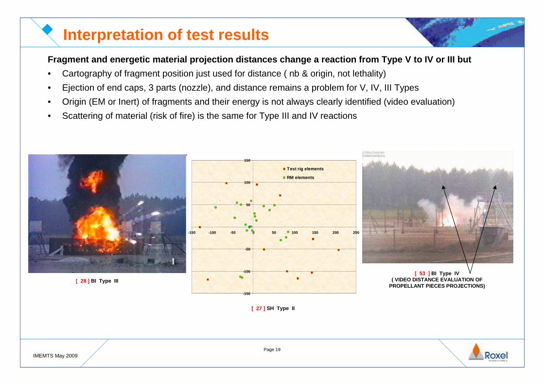
Interpretation of test resultsFragment and energetic material projection distance s change a reaction from Type V to IV or III but
• Cartography of fragment position just used for distance ( nb & origin, not lethality)
• Ejection of end caps, 3 parts (nozzle), and distance remains a problem for V, IV, III Types
• Origin (EM or Inert) of fragments and their energy is not always clearly identified (video evaluation)
• Scattering of material (risk of fire) is the same for Type III and IV reactions
[ 53 ] BI Type IV ( VIDEO DISTANCE EVALUATION OF
PROPELLANT PIECES PROJECTIONS)
[ 27 ] SH Type II
[ 28 ] BI Type III
-150
-100
-50
0
50
100
150
-150 -100 -50 0 50 100 150 200 250
Test rig elements
RM elements

Page 20IMEMTS May 2009
-60
-40
-20
0
20
40
60
80
0 2000 4000 6000 8000 10000
mBar (15 m)
µS
Reaction overpressure
Gun overpressure
Blast pressure results and the measurement accuracy is influenced by various parameters • Pressure gauge’s positions and any directional or reflection effects• Validity of threshold of 50 mbar at 5m and 15m
No Reaction statement for FI, HFI• Analysis of a stopped reaction
Interpretation of test results
Fragment mass 252 g (sphere)Fragment velocity 1813 m/sPropellant stops burning immediately after impact (More than 85% of the motor mass recovered)No Propulsion ?Several fragments Overpressure 52 mbar at 15 m
�type III ?TNT equivalent calculation method not specified• Based on explosive pressure effect• With TNT % equivalent interpretation for a partial detonation result of EM !
Heat flux never measured and used
[ 27 ] HFI : Type III OR STOPPED REACTION?

Page 21IMEMTS May 2009
IM RM response assessment conclusions
• Test conditions and interpretation should not lead to discussions
• An IM RM response assessment should always be referenced to an accessible test report which must be seriously analysed even in the case of “no-test” situation.
• To reach an homogeneous and coherent IM response assessment then it seems necessary to ask for an “Expert Committee”, able to state independently on the validity of test conditions, and propose the RM IM signature.
• RM should not be considered alone but at the munition level. For example the missile system’s reaction of a RM can be changed by the warhead reaction or its configuration standard e.g. packaged system.
• It seems necessary to update STANAG & AOP39 procedures and tables of classification.

Page 22IMEMTS May 2009
IM technologies gap, new research areas
• Case technology able to create sufficient venting in response to the SH stimulus.
• Improvement of passive PDI & LTI operation reliability.
• Development of acceptable active venting systems for FH & SH in field of smart RM.
• Development of generic, retrofittable, reusable concepts.
• Individual technologies providing full IM mitigation for a multitude of systems.
• Low cost composites cases.
• SCJ IM mitigation.
• Improvement of IM modelling response severity predictive capability.
• Investigate propellants IM ageing on IM response.
• Characterise FI IM response to rocket motor design to develop designer tool.

Page 23IMEMTS May 2009
Reference Data Base
Analysis & study of new architectures
Test plan proposal
Analysis & study of stimuli representativity
Analysis & study of IM signature during
ageing
French MOD IM ARP “APTE’’ logic

Page 24IMEMTS May 2009
Proposed ARP test plan 3 years work
French MOD IM ARP “APTE’’ test plan
PROGRAMME
DESIGNATION RM
Dem
onst
rato
r
Ste
el
TB
D
Com
posi
te
SS
L
Hig
h B
urni
ng
Rat
e H
TP
B
GA
P &
NE
PE
Igni
ter
Mem
bran
e
Foa
m in
bor
e
Wea
knes
sIn
tum
esce
nt
Pai
ntN
ew SH
SH
* H
eat r
ate
FH BI
BI*
Vel
ocity
&
calib
er
HF
I
LFI
SC
J
Ageing Effect X X X X X XHBR & RM Temperature X X X X X X X
New Stimuli X X X X X X X XNew Technology X X X X X X X X XNew Propellant X X X X X X X X
Representativity SCJ X X X X XRepresentativity FH X X X
MITIGATION DEVICE IM TEST
Inert
TYPE CASE PROPELLANT

Page 25IMEMTS May 2009
• Team Complex Weapons in the UK will require IM new products Loitering Munition (LM),
Lightweight Multi-role Missile (LMM), Common Anti-air Modular Missile (CAMM), 50A and
Future Air-to-Surface Guided Weapon (Heavy) (FASGW(H))• Low cost rocket motor
• Roxel to address IM technology gaps
• Mechanical IM threats
• UK-Energetics research programme (Foam bore)• FI mitigation techniques
• Thermal IM threats
• Continuing the recent successful SH IM results (IM Python, IM RRPR, IM HVM, IM Brimstone)
• Joint Anglo-French programme developing a low cost 2.75-inch IM solution
IM UK programmes
LM
LMM
FASGW(H) Sustain
50ACAMM
FASGW(H) Boost

Page 26IMEMTS May 2009
IM mitigation technology: is it an expensive additi on?Customers recognised that IM is a critical requirement. But IM products must be produced at a low
cost - Roxel is continuing to develop its low cost IM design methodology.
1. Technology level:
• Current high performing solutions with low cost variants
• Current design features rather than proposing costly replacement solution• Roxel’s bonded patch technology
• Future IM technology developed to mitigate a number of IM threats through a single product or design
• Proposed complete thermal and mechanical IM mitigation.
2. Rocket motor level:
• At component level understanding of the successful IM results previously obtained• Through modelling and sub-scale testing
• Without adding extra mitigation devices as example, the excellent 2530 ms-1 FI response for JCM and
Python
IM Low Cost Design Methodology

Page 27IMEMTS May 2009
3. System level:
• THA to identify the most probable and critical system configuration and target ONLY this
level to reduce the IM insertion costs to one product
• Establish the whole life costs according to a specified IM level
• Additional costs & possible financial savings analyse ACB IMEMG or CBAM MSIAC
softwares
• Produce technology which mitigates a number of munitions at once or a whole magazine
4. Productionisation level:
• Productionisation can be applied at any of the above levels to reduce the overall IM
insertion costs
• For example – a slight modification to the manufacturing tooling to improve the IM
capability of a steel case with no additional recurring costs• IM improvement from a Type I to III
IM Low Cost Design Methodology
Page 28IMEMTS May 2009
Conclusion
• IM rocket motor technology has progressed significa ntly due to numerous tests and programmes funded over the last 20 years either by MOD’s, missile primes and by Roxel’s self funded research.
• However, a technology gap still remains:
• SH mitigation devices/cases and LTI & PDI reliabili ty
• FI, SR & SCJ behaviour
• Ageing influence
• STANAG and AOP need to be updated and improved:• IM signature sometimes difficult to establish due to test conditions and interpretation
• New programmes are in progress to improve knowledge and low cost technology.
• Low cost IM solutions are the present challenge for the future.

Page 29IMEMTS May 2009
Any Questions ?
Andrew Strickland
Roxel (UK Rocket Motors) Ltd.
Tel.: +44 1562 828002
Email: [email protected]
Jean-Claude Nugeyre
Roxel France
Tel.: +33 5 56 70 75 08
Email: [email protected]
Acknowledgements & Questions
member of