rp3 and rp3s manual - rp3 rowing...
TRANSCRIPT

1 / 18
Manual for RP3 and RP3S
www.row-perfect.com

2 / 18
1.Introduction The CARE ROWPERFECT RP3 rowing simulator is the world's only rowing machine that truly simulates the dynamics of a light racing shell, freely floating on the water. The main frame with its flywheel, stretcher and seat are the boat simulating parts, and the main bar simulates the water. In it's patented design**, the flywheel assembly weighs about 21.5 kgs, which closely approximates the weight per person of most racing shells. The seat is labile, as a boat would be, forcing the rower to sit and pull symmetrically. The elasticity of the total system of main bar and flywheel assembly is designed to match closely the elasticity of the combination of oar, boat and rigger. It is however not a boat in all it's aspects. The technique of handling the oar is not required. Therefore deteriorating technique of handling the oar due to fatigue, will not serve as an automatic safeguard for the oarsman against over-exertion, as would be the case in a boat. - Because the oarsman does not have to push the oar away at the beginning of the recovery, but instead is pulled back, there is a tendency to row at a slightly higher stroke rate then in the boat. - Other than the water, the main bar is not of infinite length. Therefore, to stabilize the position of the rower within this finite length, there is a slight downward bend in the main bar, with it's lowest point at approx. 40 centimeters from the rear leg. In order to influence the dynamics of the system as little as possible, the curvature of this bend is kept at a minimum. Due to the elasticity of the main bar, and the sag resulting from the weight of the oarsman, the exact position of the lowest point of the main bar is weight dependant; of course this position also depends on the slope of the floor the unit is placed on. The unit should be leveled in such a way, that when rowing, neither of the two support legs are touched by the main frame or the seat. For leveling the unit the rear leg is provided with a level adjustment knob. Turning the knob clockwise lowers the rear end, turning it anti-clockwise raises the rear end. ** Patents: U.S.Patent 5,382,210 European Patent 0 376 403 B1

3 / 18
2.Safety. Physical. - Ensure that it is not dangerous for you to undertake a strenuous exercise.
Consult your physician! - Always warm up properly rowing easily for 5 to 10 minutes at a pulse
frequency of 120 to 130 strokes per minute. - Although the unit easily permits it, do not row at a higher stroke rate than
you would be capable of, rowing in a boat. Mechanical. - Properly install the rowing simulator with the main bar at the correct
Inclination. Adjust the inclination when front or rear legs are being touched by the main frame or the seat, by raising slightly the side that is being touched.
- The ROWPERFECT machine has not been designed for use in the vicinity of children. Keep children away when exercising. - Allow for 1 m of clear space around the machine when in use. - Keep spectators at more than an arms length from the rotating flywheel and the moving main frame. - Never touch the rotating flywheel, and do not touch the main frame when in
use. - Always pull the handle with two hands, and do not bend, twist or kink the
chain. Any abuse of the chain may result in injury. - Always place the handle into the handle hooks or against the cage before
letting go. Never let the handle fly into the cage. - Avoid ties, shawls or other clothing from being sucked into the cage by the
rotating flywheel. - Prevent objects from falling or being thrown into the rotating fan. - Wear tight clothing and keep clothing free from the seat rollers. - Maintain your machine properly as recommended in section Maintenance. Replace worn or defective parts before using the unit. In general: Treat your ROWPERFECT rowing simulator with the same loving care as you would your single scull.

4 / 18
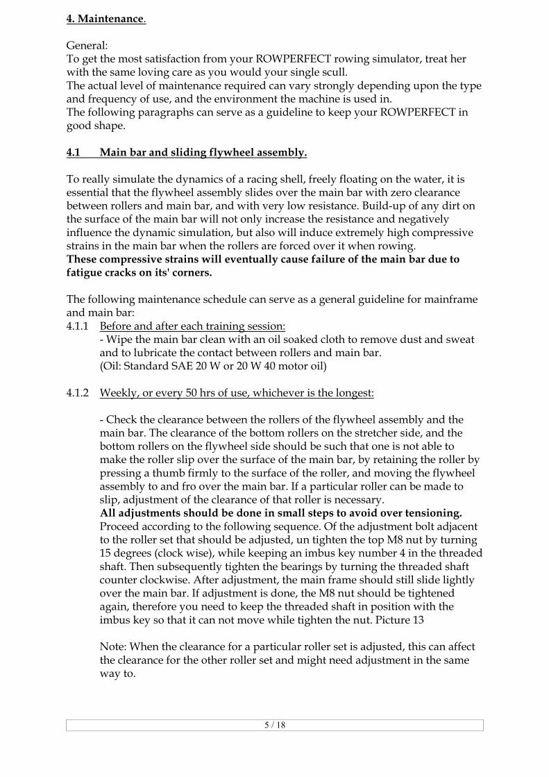
3. Assembly of the base unit. The ROWPERFECT rowing simulator comes pre-assembled into 7 separate parts: - Mainframe assembly - Main bar - Seat - Front Leg - Rear leg - Foot stretcher - Box with tools and other parts Tools needed: imbus key 6 mm and spanner size 13 for M8 nuts Assembly procedure. The main bar has one straight and one upward curved end, this upward curved end is the back end. 1- Lay the main bar on the transport box with the curved back end of the main
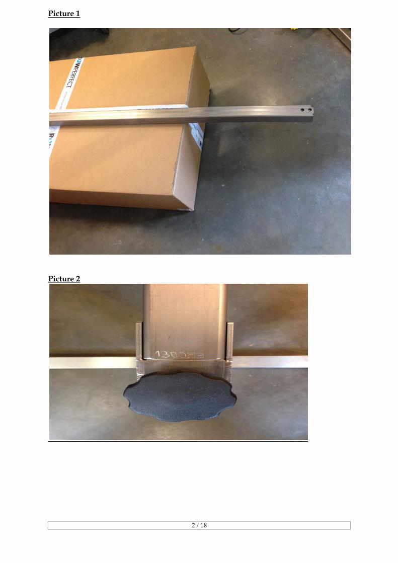
bar pointing downwards and make sure it’s clean. Picture 1. 2- Push the main bar into the rear leg, make sure the serial number is on the side
where the black knob is. Picture 2. Before inserting the 8 mm bolts make sure the holes of the leg are in line with the holes of the main bar, tighten them firm. Picture 3
3- Slide the seat onto the main bar with the double curved side of the seat
pointing towards the hind leg, see picture 4. 4- Make sure that before subsequently slide the main frame assembly onto the
main bar with the shaft side pointing away from the seat, that the parking lock system is set on green! Picture 5. Put the mainframe on the transport box. Picture 6. Push the main bar through the mainframe, don’t use extreme force it should glide through!
5- Place the front leg, make sure again that the holes are in line before inserting
the 8 mm bolts and tighten them firm. Picture 7. Place the buffer on the front leg. Picture 8.
6- The stretcher boards have a strap, both of them provided with a buckle. The
stretcher boards should be attached to the stretcher bars in such a way that the buckles point away from the main frame. Picture 9 Put the two stretcher bars through the corresponding holes in the main frame and put the stretcher grip bolts in the stretcher bars. Picture 10.
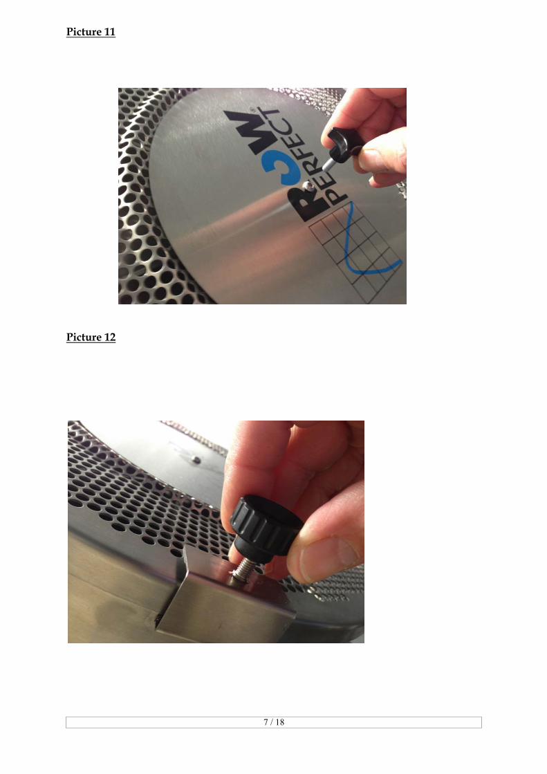
7- Screw on the knob for the disc, first take out M6 screw. Then screw on the sliding vane. Picture 11 and 12
8- The clearance between the main bar and the rollers of the main frame has
been adjusted in the factory. However, prior to using the units please check the clearance as per section 4.Maintenance and adjust if necessary.
5 / 18
4. Maintenance. General: To get the most satisfaction from your ROWPERFECT rowing simulator, treat her with the same loving care as you would your single scull. The actual level of maintenance required can vary strongly depending upon the type and frequency of use, and the environment the machine is used in. The following paragraphs can serve as a guideline to keep your ROWPERFECT in good shape. 4.1 Main bar and sliding flywheel assembly. To really simulate the dynamics of a racing shell, freely floating on the water, it is essential that the flywheel assembly slides over the main bar with zero clearance between rollers and main bar, and with very low resistance. Build-up of any dirt on the surface of the main bar will not only increase the resistance and negatively influence the dynamic simulation, but also will induce extremely high compressive strains in the main bar when the rollers are forced over it when rowing. These compressive strains will eventually cause failure of the main bar due to fatigue cracks on its' corners. The following maintenance schedule can serve as a general guideline for mainframe and main bar: 4.1.1 Before and after each training session: - Wipe the main bar clean with an oil soaked cloth to remove dust and sweat and to lubricate the contact between rollers and main bar. (Oil: Standard SAE 20 W or 20 W 40 motor oil) 4.1.2 Weekly, or every 50 hrs of use, whichever is the longest: - Check the clearance between the rollers of the flywheel assembly and the
main bar. The clearance of the bottom rollers on the stretcher side, and the bottom rollers on the flywheel side should be such that one is not able to make the roller slip over the surface of the main bar, by retaining the roller by pressing a thumb firmly to the surface of the roller, and moving the flywheel assembly to and fro over the main bar. If a particular roller can be made to slip, adjustment of the clearance of that roller is necessary.
All adjustments should be done in small steps to avoid over tensioning. Proceed according to the following sequence. Of the adjustment bolt adjacent
to the roller set that should be adjusted, un tighten the top M8 nut by turning 15 degrees (clock wise), while keeping an imbus key number 4 in the threaded shaft. Then subsequently tighten the bearings by turning the threaded shaft counter clockwise. After adjustment, the main frame should still slide lightly over the main bar. If adjustment is done, the M8 nut should be tightened again, therefore you need to keep the threaded shaft in position with the imbus key so that it can not move while tighten the nut. Picture 13
Note: When the clearance for a particular roller set is adjusted, this can affect
the clearance for the other roller set and might need adjustment in the same way to.

6 / 18
4.1.3 Every 200 hrs of use or every 4 weeks, whichever is the longest: Check that the following bolts and nuts are not loose: - The two M6 bolts holding the main bearing block - The two M8 bolts holding the bar adjustment in position. - The four Knob bolts that hold the stretcher boards. - The bolts holding the front an rear leg to the main bar. 4.2 Chain. To get the longest life from your chain and sprocket, keep the chain clean and properly lubricated at all times. Do not use too much lubricant for the chain, as this may affect the life of the elastic cord in a negative way. The following schedule can serve as a guideline for chain maintenance: 4.2.1 Weekly or every 50 hrs of use, whichever is the longest. Soak a clean rag or paper towel with approximately 5 ml of SAE 20 or 20 W 40
motor oil. Pull the chain gently all the way out, until it stops. Wipe the oil soaked rag or paper towel along the full length of the chain
repeatedly, to lubricate the chain and at the same time remove accumulated dirt and lubricant residue. Finally wipe the chain clean of any excess oil with a clean dry rag or dry paper towel.
4.2.2 Every 200 hrs of use or every 4 weeks, whichever is the longest: - Inspect the chain handle connection. Check the connector piece and the U-
bolt that connect the chain to the handle. The connector piece is attached to the chain in the factory and should be stiff connected to the chain. The U-bolt should be replaced if it is nearly half worn.
- Inspect the chain for stiff links. Stiff links can cause the chain to skip over the sprocket. This can lead to injury and causes excessive wear of both chain and sprockets. Stiff links can be caused by lack of lubrication, build-up of dirt, or mechanical abuse of the chain.
Generally repeated cleaning and lubrication, as in weekly maintenance, will loosen up the links. If this is not the case and the chain skips over the sprocket, the unit should not be used. Contact your ROWPERFECT agent for a replacement chain and sprocket.

7 / 18
5 Actions prior to start. 5.1 Levelling the unit Before starting to row, the unit should be leveled correctly, in order to allow gravity to stabilize the position of the rower at the correct place. For leveling the unit, the height of the rear leg is adjustable by means of a black knob. Turning the knob clockwise shortens the rear leg, and thus lowers the hind, turning it anti-clockwise raises the rear end. To level the unit correctly, proceed as follows: Put the unit in its proper place where it is going to be used. Sit down on the seat and place your feet on the stretcher. Then, without using the handle, sit in catch position, and push to and fro with the legs quickly over a distance of approx 10 cm a couple of times. Gravity then causes the rower to arrive at the lowest point of the bar. Properly leveled, the position of the center of the seat is then at approx. 30 cm from the rear of the main bar. Your ROWPERFECT base unit now is ready for use. When, while rowing, the main frame touches the front leg repeatedly, lower the rear by turning the knob clockwise. When, on the contrary, the seat repeatedly touches the rear leg, raise the rear leg by turning the knob anti-clockwise. 5.2 Adjusting the boat simulating characteristics. The "feel" of a racing shell depends upon a mixture of inertial forces and friction forces during the stroke and recovery cycle, the type of oar and the inboard/outboard ratio used. The flywheel assembly of the ROWPERFECT rowing simulator weighs 21.8 kgs, which is close to the average weight per person of most racing shells, including the oars. To adjust the level of friction the central part of the fan is covered by a disk and a sliding vane on top of the cage. With the combination of this disk and the vane generally the ROWPERFECT can be made to give the same "feel" as a boat. Choose that combination that simulates your boat closest. If required bigger or smaller disks can be cut by the user from similar material to fine tune. Always use full disks for adjustment of the level of friction, do not use louvers to throttle the fan at the inlet, as this will change the friction characteristics of the fan. This then will lead to erroneous readings for power and all related parameters. 5.3 Interface and software. The interface and software will operate on any PC with windows software. You can download the software and instructions on the website: http://www.row-ware.com.

8 / 18
5.4 Actions prior to start-up. Connect the interface with the interface cable to one of the COM ports of the compu-ter.(Optionally connect the pulse sensor to the interface plug.) Note: The interface derives it's energy from the COM port, no batteries are needed. The ROWPERFECT software assigns the voltage on some of the COM port contacts at the appropriate value for the interface. User identification. Introduce a new user to the system by filling out the first time you run the software. The weight, gender, boat and sprocket data are used to calculate a weight- and gender- corrected time and boat speed. These times are close to the real times made in the chosen type of boat under ideal conditions with technique in the boat near to perfect. For RP3 and RP3S you choose by sprocket the big sprocket, because there is no option for the small sprocket. For RP2 and old models RP3 the small sprocket of the rowing simulator is the left one, the big sprocket is the right one, nearest to the fan. Type of training. The type of training to be performed by the oarsman can be chosen by giving a certain amount of work to do or by indicating certain intensity. The amount of work can be expressed in terms of STROKES, ENERGY, DISTANCE or TIME. The chosen parameter then is counted down from the limitation value down to zero. At the end of the session the results are presented in DISTANCE, TIME, total ENERGY dissipated, and POWER (average over the total session in Watts). If the option INTERVALS is chosen, the number of intervals, and the units in which the intervals are going to be counted down, the required POWER during the interval, POWER during the rest period, as well as an incremental value per interval can be selected. Note: Always choose the number of intervals one higher than the number to be rowed. Further you can find an more detailed subscription of the software in the manual under HELP. The WORK SCREEN. The work screen presents a visual display of the performance of the oarsman or oarswoman in comparison to selected target values, and therefore is a very valuable tool for improving technique and for synchronizing crews during the wintertime or at great distances.
TAKE CARE, ROW PERFECT !

9 / 18
9 Parts list. The ROWPERFECT rowing simulator consists of the following sub- assemblies: 1. Main frame 2. Main bar 3. Front leg 4. Rear leg 5. Seat 6. Foot stretchers Subject to change without notice. WARRANTY. Your CARE ROWPERFECT rowing simulator is warranted against all defects in materials and workmanship for a period of two years after shipment. Normal wear and tear, and damage due to poor maintenance, is excluded from this warranty. If parts are found defective, contact your nearest ROWPERFECT agent , or our office directly: Telephone: +(31) 053 5727923, email: [email protected], website: ww.row-perfect.com To be considered for warranty replacement or repair, the defective parts must be returned, postage paid, to CARE RP3 BV, together with a description of how the piece failed and the serial number of the machine The customer is responsible for all shipping costs. The foregoing obligation is CARE RP3 BV's sole liability under this warranty, express or implied, and excludes any liability for consequential damages.

10 / 18
For more information on ROWPERFECT write or call to nay of the following addresses: CARE RP3 BV Van Limborgstraat 8 7482 KW Haaksbergen The Netherlands Tel. +(31) 523 270184 Fax +(31) 523 270185 E-mail [email protected] Jan and Annet Lammers There are agents for the following countries, see website: www.row-perfect.com Netherlands Australia Austria België Canada Czech Republic and Slovakia Germany / Deutschland Ireland
Japan New Zealand China and South East Asia Norway / Norge Spain / España Suisse / Schweiz / Svizzera United Kingdom United States of America
Subject to change without notice.
2 / 18
Picture 1
Picture 2

3 / 18
Picture 3
Picture 4

4 / 18
Picture 5
Picture 6

5 / 18
picture 7
picture 8

6 / 18
Picture 9
Picture 10
7 / 18
Picture 11
Picture 12

8 / 18
Picture 13

9 / 18
Picture 14: Content box