rs485 – jbus/modbus - socomec.com · on 1 com f gb d i nl e p diris a20 rs485 – jbus/modbus®...
TRANSCRIPT

ON1
COM
F D I NLGB E P
DIRIS A20RS485 – JBUS/MODBUS®
Notice d’utilisationOperating instructions - Bedienungsanleitung
Istruzioni per l’uso - GebruiksaanwijzingInstrucciones de servicio - Manual de instruções

2 SOCOMEC - Réf. : 876 581 D
OPERATIONS PREALABLES _____________________ 4INFORMATIONS GENERALES____________________ 4INSTALLATION _________________________________ 5PROGRAMMATION _____________________________ 6COMMUNICATION_____________________________ 11CARACTERISTIQUES TECHNIQUES _____________ 17LEXIQUE DES ABRÉVIATIONS ___________________17
PRELIMINARY OPERATIONS ___________________ 18GENERAL INFORMATION ______________________ 18INSTALLATION ________________________________ 19PROGRAMMING ______________________________ 20COMMUNICATION_____________________________ 25TECHNICAL CHARACTERISTICS________________ 31GLOSSARY OF ABREVIATIONS__________________31
VORAUSGEHENDE KONTROLLEN ______________ 32ALLGEMEINE HINWEISE _______________________ 32INSTALLATION ________________________________ 33KONFIGURATION______________________________ 34KOMMUNIKATION _____________________________ 39TECHNISCHE DATEN __________________________ 45GLOSSAR DER ABKURZUNGEN_________________45
OPERAZIONI PRELIMINARI_____________________ 46INFORMAZIONI GENERALI _____________________ 46INSTALLAZIONE_______________________________ 47PROGRAMMAZIONE___________________________ 48COMMUNICAZIONE ___________________________ 53CARATTERISTICHE TECNICHE _________________ 59ELENCO DELLE ABBREVIAZIONI ________________59
Con
tent
s
GB
Som
mai
re
F
Inha
ltsve
rzei
chni
s
D
Som
mar
io
I

3SOCOMEC - Réf. : 876 581 D
VOORAFGAANDE HANDELINGEN_______________ 60ALGEMENE INFORMATIE_______________________ 60INSTALLERING ________________________________ 61PROGRAMMERING____________________________ 62COMMUNICATIE ______________________________ 67TECHNISCHE EIGENSCHAPPEN________________ 73LEXICON VAN DE AFKORTINGEN________________73
OPERACIONES PREVIAS_______________________ 74INFORMACIONES GENERALES _________________ 74INSTALACIÓN_________________________________ 75PROGRAMACIÓN _____________________________ 76COMUNICACIÓN ______________________________ 81CARACTERíSTICAS TÉCNICAS _________________ 87LEXICO DE LAS ABREVIACIONES _______________87
OPERAÇÕES PRELIMINARES __________________ 88INFORMAÇÕES GERAIS _______________________ 88INSTALAÇÃO _________________________________ 89PROGRAMAÇÃO ______________________________ 90COMUNICAÇÃO_______________________________ 95CARACTERÍSTICAS TÉCNICAS ________________ 101LEXICO DAS ABREVIATURAS __________________101
Indi
ce
E
Indi
ce
P
Inho
ud
NL

DIRIS A20 - RS485 - JBUS/MODBUS®
OPERATIONS PREALABLES
4 SOCOMEC - Réf. : 876 581 D
FonctionsLe module option Communication doit être associé auDIRIS A20 (réf. 4825 0A20). Il met à disposition uneliaison série RS485 (2 ou 3 fils) en protocoleJBUS/MODBUS® qui permet l’exploitation duDIRIS A20 à partir d’un PC ou d’un API.
GénéralitésDans une configuration standard, une liaison RS485permet de mettre en relation 31 DIRIS ou COUNTIS Ciavec un PC ou un automate sur 1500 mètres à partirdu protocole JBUS/MODBUS®.
N 1 N 2 N n R = 120
1200 M
R = 120
Automates programmables
Autres systèmes
N 1 R = 120
Automates programmables
Autres systèmes
répéteur
RS485
0+- -+0 N n
R = 120
1200 M 1200 M
DIR
IS 1
09 E
FD
IRIS
110
E F
Recommandations :Il est nécessaire d’utiliser une paire torsadée blindéetype LIYCY. Dans un environnement perturbé ou surun réseau important en longueur et en nombre deDIRIS, nous conseillons d’utiliser une paire torsadéeblindée avec un blindage général type LIYCY-CY.Si la distance de 1200 m ou/et le nombre de 31 DIRISsont dépassés, il est nécessaire de raccorder un répéteur(1 voie) ou un éclateur (4 voies) pour permettre un rac-cordement supplémentaire de DIRIS A20 sur plus de
1200 m. Pour plus d’informations sur la méthodologiede raccordement merci de nous consulter.Nota :Aux 2 extrémités de la liaison, il est indispensable defixer une résistance de 120 ohms qui se trouve sur lemodule additionnel.
D’autres solutions existent (modem, TCP-IP, fibreoptique…).Merci de nous consulter.
Pour la sécurité du personnel et du matériel, il estimpératif de bien s’imprégner du contenu de cettenotice avant la mise en service.Au moment de la réception du colis il est nécessairede vérifier les points suivants :• l’état de l’emballage,• le produit n’a pas eu de dommage pendant le transport,
• la référence de l’appareil est conforme à votrecommande,
• l’emballage comprend le produit ainsi qu’une noticed’utilisation.
INFORMATIONS GENERALES

5SOCOMEC - Réf. : 876 581 D
F
DIRIS A20 - RS485 - JBUS/MODBUS®
INSTALLATION
RACCORDEMENT
Le module s’installe en face arrière du DIRIS A20 sur un des deux emplacements.
DIR
IS 3
42 A
DIR
IS 3
43 A
ON1
ON1
0V - +R=120Ω
DIR
IS 3
47 A
�
�
�Fixer le module sur un des deux emplacements
�Raccorder le bornier en respectant les indications.Remettre sous tension
Le DIRIS A20 doit être hors tension

DIRIS A20 - RS485 - JBUS/MODBUS®
6 SOCOMEC - Réf. : 876 581 D
DIRIS A20 - RS485 - JBUS/MODBUS®
PROGRAMMATION
Menu précédent
Menu suivant
PROG/ TEST
PROG/ TEST
PROG/ TEST
PROG/ TEST
PROG/ TEST
p.7
p.8
p.9
p.10

7SOCOMEC - Réf. : 876 581 D
DIRIS A20 - RS485 - JBUS/MODBUS®
F
DIRIS A20 - RS485 - JBUS/MODBUS®
PROGRAMMATION
ADRESSE DE COMMUNICATION
> Exemple : Adr = 10
PROG/ TEST
x 2
PROG/ TEST
x 1
PROG/ TEST
x 1
PROG/ TEST
PROG/ TEST
x 1confirm
x 5

DIRIS A20 - RS485 - JBUS/MODBUS®
PROGRAMMATION
8 SOCOMEC - Réf. : 876 581 D
VITESSE DE COMMUNICATION
> Exemple : bds = 38,4 kbauds
PROG/ TEST
x 1
PROG/ TEST
x 1 (19,2 kbauds)x 2 (38,4 kbauds)x 3 (2,4 kbauds)x 4 (4,8 kbauds)x 5 (9,6 kbauds)
PROG/ TEST
x 1confirm

9SOCOMEC - Réf. : 876 581 D
DIRIS A20 - RS485 - JBUS/MODBUS®
F
DIRIS A20 - RS485 - JBUS/MODBUS®
PROGRAMMATION
PARITE DE COMMUNICATION
> Exemple : PAr = EvEn
PROG/ TEST
x 1
PROG/ TEST
x 1 (Odd = parité impaire)x 2 (Even = parité paire)x 3 (no = sans parité)
PROG/ TEST
x 1confirm

DIRIS A20 - RS485 - JBUS/MODBUS®
10 SOCOMEC - Réf. : 876 581 D
DIRIS A20 - RS485 - JBUS/MODBUS®
PROGRAMMATION
BIT DE STOP DE COMMUNICATION> Exemple : stop = 2
PROG/ TEST
x 1
PROG/ TEST
x 1 (2 bits)x 2 (1 bit)
PROG/ TEST
x 1confirm

11SOCOMEC - Réf. : 876 581 D
F
LISTE DES PARAMETRES A VISUALISER (FONCTION 3)Tableau des valeurs affectées des rapports de transformation courant et tension sur 2 mots
Adresse Adresse Nombre Libellé UnitéDéc. Hex. de mots768 300 2 Courant phase 1 mA770 302 2 Courant phase 2 mA772 304 2 Courant phase 3 mA774 306 2 Courant du neutre mA776 308 2 tension composée U12 V/100778 30A 2 tension composée U23 V/100780 30C 2 tension composée U31 V/100782 30E 2 tension simple phase 1 V/100784 310 2 tension simple phase 2 V/100786 312 2 tension simple phase 3 V/100788 314 2 fréquence Hz/100790 316 2 Σ puissance active kW/100792 318 2 Σ puissance réactive kvar/100794 31A 2 Σ puissance apparente kVA/100796 31C 2 Σ facteur de puissance
- : capacitif et + : inductif 0,001798…839 31E…347 Réservé Constructeur838 346 2 I1 max moyenné mA840 348 2 I2 max moyenné mA842 34A 2 I3 max moyenné mA844 34C 2 Σ puissance active + max kW/100846…855 34E…357 Réservé Constructeur856 358 2 énergie active + kWh858 35A 2 énergie réactive + kvarh860…915 35C…393 Réservé Constructeur916 394 2 In max moyenné mA
DIRIS A20 communique à partir d'un protocoleJBUS/MODBUS® qui implique un dialogue selon unestructure maître/esclave. Deux dialogues sont possibles:• le maître dialogue avec un esclave (DIRIS) et attend
sa réponse• le maître dialogue avec tous les esclaves (DIRIS) sans
attendre leur réponse.
Le mode de communication est le mode RTU (RemoteTerminal Unit) avec des caractères hexadécimauxcomposés au minimum de 8 bits.
Conformément au protocole JBUS/MODBUS®, letemps intercaractère doit être inférieur à 3 silences,c’est-à-dire au temps d'émission de 3 caractères pourque le message soit traité par le DIRIS.Pour exploiter correctement les informations, il estindispensable d’utiliser les fonctions :
3 : pour la lecture de n mots (maximum 128).6 : pour l’écriture d’un mot.8 : pour le diagnostic des échanges entre le maître et
l'esclave à partir des compteurs 1, 3, 4, 5 et 6.16 : pour l’écriture de n mots (maximum 128).
Nota :En sélectionnant l’adresse de l’esclave 0, on transmetun message à tous les appareils présents sur le réseau(uniquement pour les fonctions 6 et 16).
TRAME DE COMMUNICATION STANDARD
Adresse de l’esclave Code de la fonction Adresse Données CRC 16
DIRIS A20 - RS485 - JBUS/MODBUS®
COMMUNICATION
Elle est composée de :

12 SOCOMEC - Réf. : 876 581 D
DIRIS A20 - RS485 - JBUS/MODBUS®
COMMUNICATION
Tableau des valeurs non affectées des rapports de transformation courant et tension sur 1 mot
LISTE DES PARAMETRES A VISUALISER (FONCTION 3)Tableau des valeurs non affectées des rapports de transformation courant et tension sur 1 mot
Adresse Adresse Nombre Libellé UnitéDéc. Hex. de mots2816 B00 1 courant phase 1 mA2817 B01 1 courant phase 2 mA2818 B02 1 courant phase 3 mA2819 B03 1 courant du neutre mA2820 B04 1 tension composée U12 V/1002821 B05 1 tension composée U23 V/1002822 B06 1 tension composée U31 V/1002823 B07 1 tension simple phase 1 V/1002824 B08 1 tension simple phase 2 V/1002825 B09 1 tension simple phase 3 V/1002826 B0A 1 fréquence Hz/1002827 B0B 1 Σ puissance active kW/1002828 B0C 1 Σ puissance réactive kvar/1002829 B0D 1 Σ puissance apparente kVA/1002830 B0E 1 Σ facteur de puissance
- : capacitif et + : inductif 0,0012831 B0F 1 I1 max moyenné mA2832 B10 1 I2 max moyenné mA2833 B11 1 I3 max moyenné mA2834 B12 1 In max moyenné mA2835 B13 1 Σ puissance active + max moyennée kW/1002836 B14 1 énergie active + < 10 000 kWh2837 B15 1 énergie active + > 10 000 kWh2838 B16 1 énergie réactive + < 10 000 kvarh2839 B17 1 énergie réactive + > 10 000 kvarh
Adresse Adresse Nombre Libellé UnitéDéc. Hex. de mots1792 700 1 courant phase 1 mA1793 701 1 courant phase 2 mA1794 702 1 courant phase 3 mA1795 703 1 courant du neutre mA1796 704 1 tension composée U12 V/1001797 705 1 tension composée U23 V/1001798 706 1 tension composée U31 V/1001799 707 1 tension simple phase 1 V/1001800 708 1 tension simple phase 2 V/1001801 709 1 tension simple phase 3 V/1001802 70A 1 fréquence Hz/1001803 70B 1 Σ puissance active kW/1001804 70C 1 Σ puissance réactive kvar/1001805 70D 1 Σ puissance apparente kVA/1001806 70E 1 Σ facteur de puissance
- : capacitif et + : inductif 0,0011807…1826 710…722 Réservé Constructeur1827 723 1 I1 max moyenné mA1828 724 1 I2 max moyenné mA1829 725 1 I3 max moyenné mA1830 726 1 Σ puisssance active + max moyenné kW/1001831…1834 727…72A Réservé Constructeur1835 72B 1 énergie active + < 10 000 kWh1836 72C 1 énergie active + > 10 000 kWh1837 72D 1 énergie réactive + < 10 000 kvarh1838 72E 1 énergie réactive + > 10 000 kvarh1839…1890 72F…762 Réservé Constructeur1891 763 1 In max moyenné mA

13SOCOMEC - Réf. : 876 581 D
DIRIS A20 - RS485 - JBUS/MODBUS®
F
DIRIS A20 - RS485 - JBUS/MODBUS®
COMMUNICATION
LISTE DES PARAMETRES A VISUALISER (FONCTION 3)Tableau des Taux de Distorsions Harmoniques (THD)
Adresse Nombre Libellé UnitéDéc. Hex. de mots2304 900 1 thd I1 0,1%2305 901 1 thd I2 0,1%2306 902 1 thd I3 0,1%2307 903 1 Réservé constructeur2308 904 1 thd U12 0,1%2309 905 1 thd U23 0,1%2310 906 1 thd U31 0,1%2311 907 1 thd V1 0,1%2312 908 1 thd V2 0,1%2313 909 1 thd V3 0,1%

DIRIS A20 - RS485 - JBUS/MODBUS®
COMMUNICATION
14 SOCOMEC - Réf. : 876 581 D
Adresse Adresse Nombre Libellé UnitéDéc. Hex. de mots256 100 1 0 : aucune option
1 : option comptage2 : option communication /
257 101 / Réservé Constructeur258 102 1 Option slot 1
0xFF : aucune option0x0 : option comptage0x1 : option communication /
259 103 1 Option slot 20xFF : aucune option0x0 : option comptage0x1 : option communication /
LISTE DES PARAMETRES A VISUALISER (FONCTION 3)Tableau de reconnaissance des options
Nota : si plusieurs options sont utilisées, il est néces-saire d’additionner le chiffre correspondant à l’option.
Exemple : comptage + communication correspondraau chiffre 3, c’est-à-dire 1 + 2.

15SOCOMEC - Réf. : 876 581 D
DIRIS A20 - RS485 - JBUS/MODBUS®
F
Adresse Adresse Nombre Libellé UnitéDéc. Hex. de mots512 200 1 Type de réseau :
0 : 1BL1 : 2BL2 : 3BL3 : 3NBL4 : 4BL5 : 4NBL /
513 201 1 Secondaire TC :5 : 5A A
514 202 1 Primaire du TC A515…518 203…206 Réservé Constructeur519 207 1 Synchronisation de I MAX :
2 : 2 secondes5 : 5 minutes8 : 8 minutes10 : 10 minutes15 : 15 minutes20 : 20 minutes30 : 30 minutes60 : 60 minutes /
520 208 1 Synchronisation de P MAX :2 : 2 secondes5 : 5 minutes8 : 8 minutes10 : 10 minutes15 : 15 minutes20 : 20 minutes30 : 30 minutes60 : 60 minutes /
521 209 1 Affectation de OUT :0 : kWh +1 : kvarh + /
LISTE DES PARAMETRES A VISUALISER OU A CONFIGURER (FONCTIONS 3, 6 ET 16)

DIRIS A20 - RS485 - JBUS/MODBUS®
COMMUNICATION
16 SOCOMEC - Réf. : 876 581 D
Adresse Adresse Nombre Libellé UnitéDéc. Hex. de mots1024 400 1 R.A.Z de :
Max 4I : 0x1Max P+ : 0x2kWh+ : 0x80kvarh+ : 0x100tous les paramètres : 0x1000 /
REMISE A ZERO DES COMPTEURS D'ENERGIE ET DES VALEURS MAX. (FONCTION 6)
LISTE DES PARAMETRES A VISUALISER OU A CONFIGURER (FONCTIONS 3, 6 ET 16)
522 20A 1 Poids d'impulsions OUT :0 : 0,1 kWh/kvarh1 : 1 kWh/kvarh2 : 10 kWh/kvarh3 : 100 kWh/kvarh4 : 1000 kWh/kvarh5 : 10000 kWh/kvarh /
523 20B 1 Durée d'impulsions OUT :1 : 100 ms2 : 200 ms3 : 300 ms4 : 400 ms5 : 500 ms6 : 600 ms7 : 700 ms8 : 800 ms9 : 900 ms /
Adresse Adresse Nombre Libellé UnitéDéc. Hex. de mots
Esclave
05
Fonction
06
Adressepoids fort
02
Adressepoids faible
00
Valeurpoids fort
00
Valeurpoids faible
05
CRC 16
49F5
Exemple:Configuration d’un réseau 4 fils non équilibré (4 NBL)pour le DIRIS numéro 5.
Réponse du DIRIS A20 : identique au message envoyé.
Nota :Pour remettre à zéro plusieurs paramètres, il estnécessaire d’additionner le chiffre correspondantindiqué dans la colonne «Libellé ».
Exemple : Remise à zéro de Max P+ et kvarh +: 2 + 100 = 102 (Hex)
Réponse du DIRIS A20 : identique au message envoyé.
Esclave
05
Fonction
06
Adressepoids fort
04
Adressepoids faible
00
Valeurpoids fort
01
Valeurpoids faible
02
CRC 16
092F

17SOCOMEC - Réf. : 876 581 D
DIRIS A20 - RS485 - JBUS/MODBUS®
COMMUNICATION /CARACTERISTIQUES TECHNIQUES
F
COMMUNICATION
COMMANDE SAUVEGARDE (RESET)
Après avoir modifié les paramètres de programmationet pour les enregistrer dans le DIRIS numéro 5, il estnécessaire de programmer cette commande.
Nota :Le DIRIS A20 ne répond pas à cette commande.
Esclave
05
Fonction
06
Adressepoids fort
06
Adressepoids faible
00
Valeur
0000
CRC 16
88C6
CARACTERISTIQUES TECHNIQUES
RS485 2 ou 3 fils half duplexProtocole JBUS/MODBUS® mode RTUVitesse de 2400 à 38400 BaudsIsolation galvanique 2,5 kV
LEXIQUE DES ABREVIATIONS
COM Communication ADR Adresse de l’esclaveBDS Vitesse de communication en bauds (bits par seconde)PAR Parité de la trame de communicationNO Sans paritéEven Parité paireOdd Parité impaireSTOP Bip de stop de la trame1 1 bit de stop2 2 bits de stop
UL - CSA APPROVAL
Normes UL 61010-1CSA-C22.2 No. 61010-1
Certificat N° de dossier UL : E257746N° de rapport CSA DIRIS A20 : 1810571N° de rapport CSA DIRIS A40 : 1810577

DIRIS A20 - RS485 - JBUS/MODBUS®
PRELIMINARY OPERATIONS
18 SOCOMEC - Réf. : 876 581 D
FunctionsThe optional Communication module must beconnected to the DIRIS A20 (ref. 4825 0A20). It pro-vides an RS485 serial link (2 or 3 wires) withJBUS/MODBUS® protocol for the use of DIRIS A20from a PC or PLC.
General pointsFor a standard configuration, an RS 485 link is used toconnect up to 31 DIRIS A20 or COUNTIS Ci with aPC or a PLC over a distance of 1500 metres, usingJBUS/MODBUS© protocol.
N 1 N 2 N n R = 120
1200 M
R = 120
Programmablecontrollers
Other systems
N 1 R = 120
Programmablecontrollers
Other systems
repetor
RS485
0+- -+0 N n
R = 120
1200 M 1200 M
DIR
IS 1
09 E
GB
DIR
IS 1
10 E
GB
Recommendations:You should use a shielded twisted pair (LIYCY type). Ina disturbed environment or large network (in terms oflength) we recommend the use of a shielded twistedpair (type LIYCY-CY).A repeater (1 channel) or an arrestor (4 channels)should be used if you intend to exceed the distance(1200 m) and/or maximum number (31) of DIRIS.Please contact us for more information.
NB:A 120 ohm resistance (found on the additional module)must be fixed at both ends of the link.
Other solutions are available (modem, TCP-IP, opticalfibre, etc.). Please contact us
For personnel and product safety please read thecontents of these operating instructions carefullybefore connecting.Check the following points as soon as you receivethe Diris A 20 package:• the packing is in good condition,• the product has not been damaged during transit,
• the product reference number conforms to yourorder,
• the package contains the product and the operatinginstructions.
GENERAL INFORMATION

GB
19SOCOMEC - Réf. : 876 581 D
DIRIS A20 - RS485 - JBUS/MODBUS®
INSTALLATION
CONNECTION
The module is fitted onto the back of the DIRIS A20 in one of the two positions provided.
DIR
IS 3
42 A
DIR
IS 3
43 A
ON1
ON1
0V - +R=120Ω
DIR
IS 3
47 A
�
�
�Fix the module in one of the two positions.
�Follow indications when connecting the terminal.Switch on voltage supply.
The DIRIS A20 must be switched off

DIRIS A20 - RS485 - JBUS/MODBUS®
PROGRAMMING
20 SOCOMEC - Réf. : 876 581 D
Previous menu
Following menu
PROG/ TEST
PROG/ TEST
PROG/ TEST
PROG/ TEST
PROG/ TEST
p.19
p.20
p.21
p.22

21SOCOMEC - Réf. : 876 581 D
DIRIS A20 - RS485 - JBUS/MODBUS®
PROGRAMMING
GB
COMMUNICATION ADDRESS
> Example : Adr = 10
PROG/ TEST
x 2
PROG/ TEST
x 1
PROG/ TEST
x 1
PROG/ TEST
PROG/ TEST
x 1confirm
x 5

DIRIS A20 - RS485 - JBUS/MODBUS®
PROGRAMMING
22 SOCOMEC - Réf. : 876 581 D
COMMUNICATION SPEED
> Example : bds = 38,4 kbauds
PROG/ TEST
x 1
PROG/ TEST
x 1 (19,2 kbauds)x 2 (38,4 kbauds)x 3 (2,4 kbauds)x 4 (4,8 kbauds)x 5 (9,6 kbauds)
PROG/ TEST
x 1confirm

23SOCOMEC - Réf. : 876 581 D
DIRIS A20 - RS485 - JBUS/MODBUS®
PROGRAMMING
GB
COMMUNICATION PARITY
> Example : PAr = EvEn
PROG/ TEST
x 1
PROG/ TEST
x 1 (Odd = odd parity)x 2 (Even = par parity)x 3 (no = without parity)
PROG/ TEST
x 1confirm

DIRIS A20 - RS485 - JBUS/MODBUS®
PROGRAMMING
24 SOCOMEC - Réf. : 876 581 D
COMMUNICATION STOP BIT> Example : stop = 2
PROG/ TEST
x 1
PROG/ TEST
x 1 (2 bits)x 2 (1 bit)
PROG/ TEST
x 1confirm

25SOCOMEC - Réf. : 876 581 D
DIRIS A20 - RS485 - JBUS/MODBUS®
GB
LIST OF PARAMETERS TO BE DISPLAYED (FUNCTION 3)Table of values with allocated current and voltage winf-ding ratios on 2 words
Decimal Hexa. Number Text Unitaddress address of words768 300 2 phase 1 current mA770 302 2 phase 2 current mA772 304 2 phase 3 current mA774 306 2 neutral current mA776 308 2 phase to phase voltage U12 V/100778 30A 2 phase to phase voltage U23 V/100780 30C 2 phase to phase voltage U31 V/100782 30E 2 phase to neutral voltage phase 1 V/100784 310 2 phase to neutral voltage phase 2 V/100786 312 2 phase to neutral voltage phase 3 V/100788 314 2 frequency Hz/100790 316 2 Σ active power kW/100792 318 2 Σ reactive power kvar/100794 31A 2 Σ apparent power kVA/100796 31C 2 Σ power factor
-: leading and +: lagging 0,001798…839 31E…347 Reserved manufacturer 838 346 2 average value I1 max mA840 348 2 average value I2 max mA842 34A 2 average value I3 max mA844 34C 2 Σ active power + max kW/100846…855 34E…357 Reserved manufacturer856 358 2 active energy + kWh858 35A 2 reactive energy + kvarh860…915 35C…393 Reserved manufacturer 916 394 2 average value In max mA
The JBUS/MODBUS® used by the DIRIS A20 involvesa dialogue using a master-slave hierarchical structure.There are two possible dialogues:• the master communicates with a slave (DIRIS) and
waits for its reply• the master communicates with all the slaves (DIRIS)
without waiting for their reply.
The mode of communication is the RTU (RemoteTerminal Unit) using hexadecimal characters of at least8 bits.
According to the JBUS/MODBUS® protocol, transmissiontime must be less than 3 silences, i.e. the emission timeof 3 characters so that the message is processed bythe DIRIS.To correctly use information, the following functions areimportant:
3 : to read n words (maximum 128).6 : to write one word.8 : to diagnose exchanges between the master and
the slave via meters 1, 3, 4, 5 and 6.16 : to write n words (maximum 128).
NB:When selecting slave address 0, a message is sent toall the instruments present on the network (only forfunctions 6 and 16).
THE STANDARD COMMUNICATIONS FRAME
Slave address Function code Address Data CRC 16
DIRIS A20 - RS485 - JBUS/MODBUS®
COMMUNICATION
The standard communications frame consists of:

DIRIS A20 - RS485 - JBUS/MODBUS®
26 SOCOMEC - Réf. : 876 581 D
DIRIS A20 - RS485 - JBUS/MODBUS®
COMMUNICATION
Table of values with allocated current and voltage winf-ding ratios on 1 word
LIST OF PARAMETERS TO BE DISPLAYED (FUNCTION 3)Table of values with allocated current and voltage winf-ding ratios on 1 word
Decimal Hexa. Number Text Unitaddress address of words2816 B00 1 phase 1 current mA2817 B01 1 phase 2 current mA2818 B02 1 phase 2 current mA2819 B03 1 neutral current mA2820 B04 1 phase to phase voltage U12 V/1002821 B05 1 phase to phase voltage U23 V/1002822 B06 1 phase to phase voltage U31 V/1002823 B07 1 phase to neutral voltage phase 1 V/1002824 B08 1 phase to neutral voltage phase 2 V/1002825 B09 1 phase to neutral voltage phase 3 V/1002826 B0A 1 frequency Hz/1002827 B0B 1 Σ active power kW/1002828 B0C 1 Σ reactive power kvar/1002829 B0D 1 Σ apparent power kVA/1002830 B0E 1 Σ power factor
-: leading and +: lagging 0,0012831 B0F 1 average value I1 max mA2832 B10 1 average value I2 max mA2833 B11 1 average value I2 max mA2834 B12 1 average value In max mA2835 B13 1 Σ active power + average value max kW/1002836 B14 1 active power + < 10 000 kWh2837 B15 1 active power + > 10 000 kWh2838 B16 1 reactive power + < 10 000 kvarh2839 B17 1 reactive power + > 10 000 kvarh
Decimal Hexa. Number Text Unitaddress address of words1792 700 1 phase 1 current mA1793 701 1 phase 2 current mA1794 702 1 phase 3 current mA1795 703 1 neutral current mA1796 704 1 phase to phase voltage U12 V/1001797 705 1 phase to phase voltage U23 V/1001798 706 1 phase to phase voltage U31 V/1001799 707 1 phase to neutral voltage phase 1 V/1001800 708 1 phase to neutral voltage phase 2 V/1001801 709 1 phase to neutral voltage phase 3 V/1001802 70A 1 frequency Hz/1001803 70B 1 Σ active power kW/1001804 70C 1 Σ reactive power kvar/1001805 70D 1 Σ apparent power kVA/1001806 70E 1 Σ power factor
-: leading and +: lagging 0,0011807…1826 710…722 Reserved manufacturer 1827 723 1 average value I1 max mA1828 724 1 average value I2 max mA1829 725 1 average value I3 max mA1830 726 1 Σ active power + average value max kW/1001831…1834 727…72A Reserved manufacturer 1835 72B 1 active power + < 10 000 kWh1836 72C 1 active power + > 10 000 kWh1837 72D 1 reactive power + < 10 000 kvarh1838 72E 1 reactive power + > 10 000 kvarh1889…1890 72F…762 Reserved manufacturer 1891 763 1 average value In max mA
27SOCOMEC - Réf. : 876 581 D
DIRIS A20 - RS485 - JBUS/MODBUS®
GB
DIRIS A20 - RS485 - JBUS/MODBUS®
COMMUNICATION
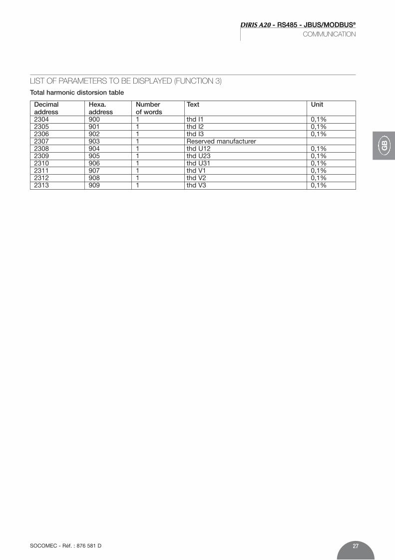
LIST OF PARAMETERS TO BE DISPLAYED (FUNCTION 3)Total harmonic distorsion table
Decimal Hexa. Number Text Unitaddress address of words2304 900 1 thd I1 0,1%2305 901 1 thd I2 0,1%2306 902 1 thd I3 0,1%2307 903 1 Reserved manufacturer2308 904 1 thd U12 0,1%2309 905 1 thd U23 0,1%2310 906 1 thd U31 0,1%2311 907 1 thd V1 0,1%2312 908 1 thd V2 0,1%2313 909 1 thd V3 0,1%

DIRIS A20 - RS485 - JBUS/MODBUS®
COMMUNICATION
28 SOCOMEC - Réf. : 876 581 D
Decimal Hexa. Number Text Unitaddress address of words256 100 1 0 : no option
1 : metering option2 : communication option /
257 101 / Reserved manufacturer 258 102 1 option slot 1
0xFF : no option0x0 : metering option0x1 :communication option /
259 103 1 option slot 20xFF : no option0x0 : metering option0x1 : communication option /
LIST OF PARAMETERS TO BE DISPLAYED (FUNCTION 3)Option recognition table
NB: if several options are used, the number corres-ponding to the option must be added.
Example : metering + communication will correspondat number 3, that’s to say 1 + 2.

29SOCOMEC - Réf. : 876 581 D
DIRIS A20 - RS485 - JBUS/MODBUS®
COMMUNICATION
GB
Decimal Hexa. Number Text Unitaddress address of words512 200 1 Network type :
0 : 1BL1 : 2BL2 : 3BL3 : 3NBL4 : 4BL5 : 4NBL /
513 201 1 CT secondary :5 : 5A A
514 202 1 CT primary A515…518 203…206 Reserved manufacturer 519 207 1 Synchronisation of I MAX :
2 : 2 sec5 : 5 minutes8 : 8 minutes10 : 10 minutes15 : 15 minutes20 : 20 minutes30 : 30 minutes60 : 60 minutes /
520 208 1 Synchronisation of P MAX :2 : 2 sec5 : 5 minutes8 : 8 minutes10 : 10 minutes15 : 15 minutes20 : 20 minutes30 : 30 minutes60 : 60 minutes /
521 209 1 OUT allocation :0 : kWh +1 : kvarh + /
LIST OF PARAMETERS TO BE DISPLAYED OR PROGRAMMED (FUNCTIONS 3, 6 AND 16)

DIRIS A20 - RS485 - JBUS/MODBUS®
30 SOCOMEC - Réf. : 876 581 D
DIRIS A20 - RS485 - JBUS/MODBUS®
COMMUNICATION
Decimal Hexa. Number Text Unitaddress address of words1024 400 1 R.A.Z de :
Max 4I : 0x1Max P+ : 0x2kWh+ : 0x80kvarh+ : 0x100All parameters : 0x1000 /
RESET TO ZERO: ENERGY METERS AND MAX. VALUES (FUNCTION 6 )
LIST OF PARAMETERS TO BE DISPLAYED OR PROGRAMMED (FUNCTIONS 3, 6 AND 16)
522 20A 1 OUT impulse value :0 : 0,1 kWh/kvarh1 : 1 kWh/kvarh2 : 10 kWh/kvarh3 : 100 kWh/kvarh4 : 1000 kWh/kvarh5 : 10000 kWh/kvarh /
523 20B 1 OUT impulse duration :1 : 100 ms2 : 200 ms3 : 300 ms4 : 400 ms5 : 500 ms6 : 600 ms7 : 700 ms8 : 800 ms9 : 900 ms /
Decimal Hexa. Number Text Unitaddress address of words
Slave
05
Function
06
High-orderaddress
02
Low-orderaddress
00
High-ordervalue
00
Low-ordervalue
05
CRC 16
49F5
Example:Configuration of a 4-wired unbalanced network(4 NBL) for DIRIS number 5.
DIRIS A20 reply: Identical to message sent
NB:To reset several parameters to zero, add the corresponding figure indicated in the “text” column.
Example: Reset Max P+ and kvarh + to zero: 2 + 100 = 102 (Hex).
DIRIS A20 reply: identical to the message sent.
Slave
05
Function
06
High-orderaddress
04
Low-orderaddress
00
High-ordervalue
01
Low-ordervalue
02
CRC 16
092F
31SOCOMEC - Réf. : 876 581 D
DIRIS A20 - RS485 - JBUS/MODBUS®
GB
DIRIS A20 - RS485 - JBUS/MODBUS®
COMMUNICATION / TECHNICAL CARACTERITICS
COMMUNICATION
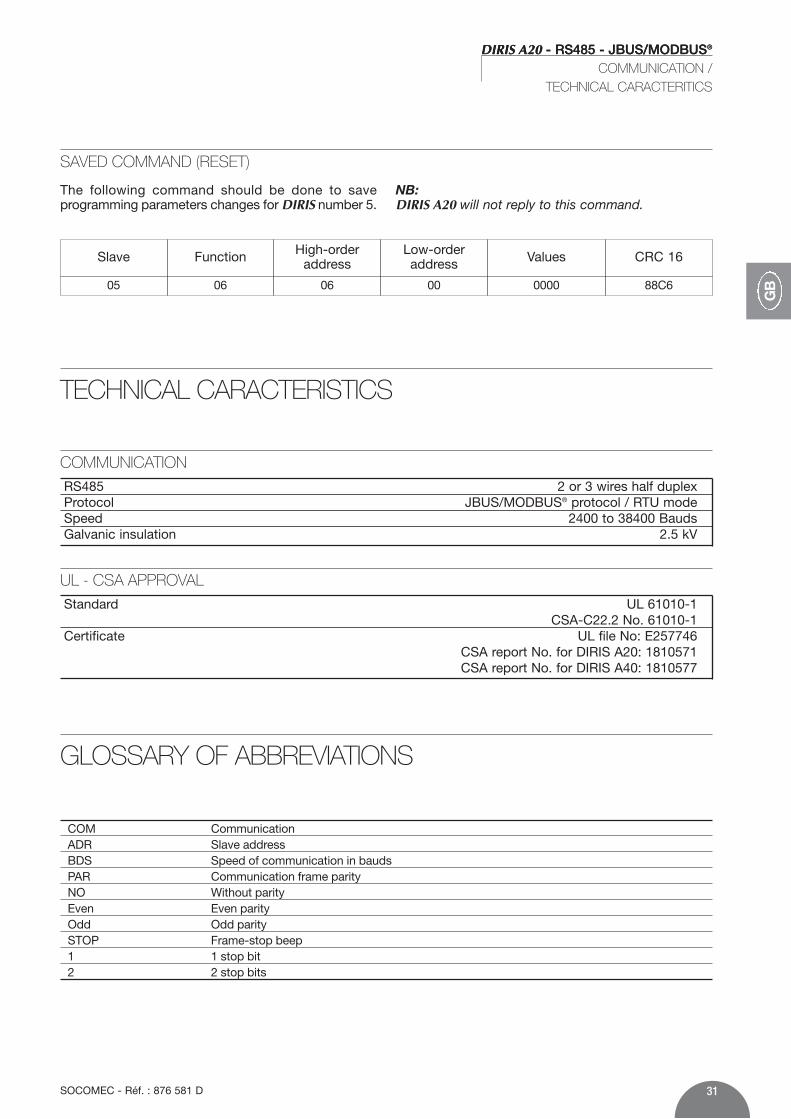
SAVED COMMAND (RESET)
The following command should be done to save programming parameters changes for DIRIS number 5.
NB:DIRIS A20 will not reply to this command.
Slave
05
Function
06
High-orderaddress
06
Low-orderaddress
00
Values
0000
CRC 16
88C6
TECHNICAL CARACTERISTICS
RS485 2 or 3 wires half duplexProtocol JBUS/MODBUS® protocol / RTU modeSpeed 2400 to 38400 BaudsGalvanic insulation 2.5 kV
GLOSSARY OF ABBREVIATIONS
COM Communication ADR Slave addressBDS Speed of communication in baudsPAR Communication frame parityNO Without parityEven Even parityOdd Odd paritySTOP Frame-stop beep1 1 stop bit2 2 stop bits
UL - CSA APPROVAL
Standard UL 61010-1CSA-C22.2 No. 61010-1
Certificate UL file No: E257746CSA report No. for DIRIS A20: 1810571CSA report No. for DIRIS A40: 1810577

DIRIS A20 - RS485 - JBUS/MODBUS®
32 SOCOMEC - Réf. : 876 581 D
DIRIS A20 - RS485 - JBUS/MODBUS®
VORAUSGEHENDE KONTROLLEN
FunktionenDas Optionsmodul Kommunikation muss mit DIRISA20 verbunden sein (ref. 4825 0A20). Es bietet eineserielle Verbindung vom Typ RS485 (mit 2 oder 3Drähten) im Protokoll JBUS/MODBUS® und ermög-licht somit den Betrieb des DIRIS A20 über einen PCoder API.
AllgemeinesIn der Grundausführung erlaubt eine serielle RS 485-Schnittstelle die Verbindung von bis zu 31DIRIS A20 oder COUNTIS Ci mit einem PC oder einer SPS-Steuerung über 1500 Metern via JBUS/MODBUS®-Protokoll.
N 1 N 2 N n R = 120
1200 M
R = 120
SPS-Steuerungen
Andere Systeme
N 1 R = 120
SPS- Steuerungen
Andere Systeme
Verstärker
RS485
0+- -+0 N n
R = 120
1200 M 1200 M
DIR
IS 1
09 E
DD
IRIS
110
E D
Empfehlungen:Wir empfehlen eine verdrillte und abgeschirmteDoppelleitung von Typ LIYCY. Unter schwierigenBedingungen oder in einem größeren Netz (in Längeund Anzahl von Geräten) empfehlen wir eine verdrillteund abgeschirmte Doppelleitung von Typ LIYCY-CY.Bei weiteren Strecken (über 1200 m) und/oder einergrößeren Anzahl von Geräten (mehr als 31 DIRIS) mußein Verstärker (1 Kanal) oder ein Repeater (4 Kanäle)eingesetzt werden (bitte anfragen).
Hinweis:An den beiden Enden der Verbindung muß einWiderstand von 120 Ohm vorgesehen werden, dersich auf dem zusätzlichen Modul befindet.Wir bieten noch andere Lösungen (Modem, TCP-IP,LWL…). Bitte anfragen.
Für die Sicherheit von Personen und Anlagen lesenSie dieses Handbuch aufmerksam durch, bevor dasGerät in Betrieb genommen wird.Bei Empfang des Gerätes DIRIS A20 muß folgendesüberprüft werden:• Zustand der Verpackung,• Sind Transportschäden zu melden?
• Entspricht der Packungsinhalt Ihrer Bestellung?• Die Verpackung enthält das Produkt und die
Bedienungsanleitung.
ALLGEMEINE HINWEISE

33SOCOMEC - Réf. : 876 581 D
D
DIRIS A20 - RS485 - JBUS/MODBUS®
INSTALLATION
ANSCHLUSS
Das Modul wird auf der Rückseite des DIRIS an einem der zwei hierfür vorgesehenen Plätze eingebaut.
DIR
IS 3
42 A
DIR
IS 3
43 A
ON1
ON1
0V - +R=120Ω
DIR
IS 3
47 A
�
�
�Befestigen Sie das Modul an einem der zwei Plätze
�Für den Anschluß der Klemmleiste beachten Sie dieentsprechenden Hinweise.Wieder einschalten.
Der DIRIS A20 darf nicht unterSpannung stehen
DIRIS A20 - RS485 - JBUS/MODBUS®
KONFIGURATION
34 SOCOMEC - Réf. : 876 581 D
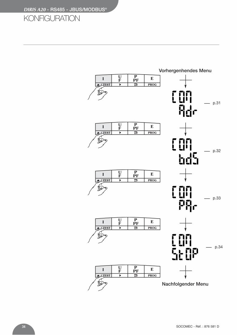
Vorhergenhendes Menu
Nachfolgender Menu
PROG/ TEST
PROG/ TEST
PROG/ TEST
PROG/ TEST
PROG/ TEST
p.31
p.32
p.33
p.34

35SOCOMEC - Réf. : 876 581 D
DIRIS A20 - RS485 - JBUS/MODBUS®
KONFIGURATION
D
KOMMUNIKATIONSADRESSE
> Beispiel: Adr = 10
PROG/ TEST
x 2
PROG/ TEST
x 1
PROG/ TEST
x 1
PROG/ TEST
PROG/ TEST
x 1confirm
x 5

DIRIS A20 - RS485 - JBUS/MODBUS®
KONFIGURATION
36 SOCOMEC - Réf. : 876 581 D
UBERTRAGUNGSGESCHWINDIGKEIT
> Beispiel: bds = 38,4 kbauds
PROG/ TEST
x 1
PROG/ TEST
x 1 (19,2 kbauds)x 2 (38,4 kbauds)x 3 (2,4 kbauds)x 4 (4,8 kbauds)x 5 (9,6 kbauds)
PROG/ TEST
x 1confirm

37SOCOMEC - Réf. : 876 581 D
DIRIS A20 - RS485 - JBUS/MODBUS®
KONFIGURATION
D
PARITÄT
> Beispiel: PAr = EvEn
PROG/ TEST
x 1
PROG/ TEST
x 1 (Odd = gerade Parität)x 2 (Even = ungerad Parität)x 3 (no = ohne Parität)
PROG/ TEST
x 1confirm

DIRIS A20 - RS485 - JBUS/MODBUS®
38 SOCOMEC - Réf. : 876 581 D
DIRIS A20 - RS485 - JBUS/MODBUS®
KONFIGURATION
STOP-BITS> Beispiel: stop = 2
PROG/ TEST
x 1
PROG/ TEST
x 1 (2 bits)x 2 (1 bit)
PROG/ TEST
x 1confirm
39SOCOMEC - Réf. : 876 581 D
DIRIS A20 - RS485 - JBUS/MODBUS®
D
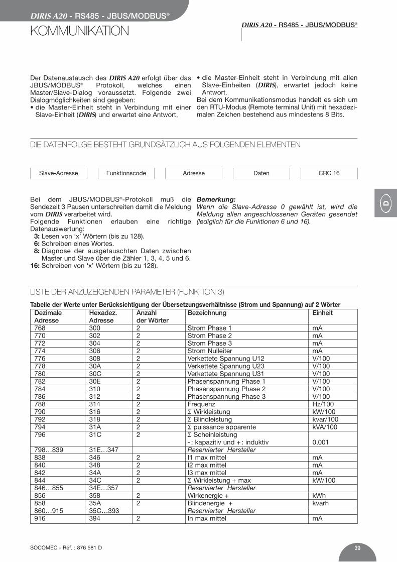
LISTE DER ANZUZEIGENDEN PARAMETER (FUNKTION 3)
Tabelle der Werte unter Berücksichtigung der Übersetzungsverhältnisse (Strom und Spannung) auf 2 WörterDezimale Hexadez. Anzahl Bezeichnung EinheitAdresse Adresse der Wörter768 300 2 Strom Phase 1 mA770 302 2 Strom Phase 2 mA772 304 2 Strom Phase 3 mA774 306 2 Strom Nulleiter mA776 308 2 Verkettete Spannung U12 V/100778 30A 2 Verkettete Spannung U23 V/100780 30C 2 Verkettete Spannung U31 V/100782 30E 2 Phasenspannung Phase 1 V/100784 310 2 Phasenspannung Phase 2 V/100786 312 2 Phasenspannung Phase 3 V/100788 314 2 Frequenz Hz/100790 316 2 Σ Wirkleistung kW/100792 318 2 Σ Blindleistung kvar/100794 31A 2 Σ puissance apparente kVA/100796 31C 2 Σ Scheinleistung
- : kapazitiv und + : induktiv 0,001798…839 31E…347 Reservierter Hersteller838 346 2 I1 max mittel mA840 348 2 I2 max mittel mA842 34A 2 I3 max mittel mA844 34C 2 Σ Wirkleistung + max kW/100846…855 34E…357 Reservierter Hersteller856 358 2 Wirkenergie + kWh858 35A 2 Blindenergie + kvarh860…915 35C…393 Reservierter Hersteller916 394 2 In max mittel mA
Der Datenaustausch des DIRIS A20 erfolgt über dasJBUS/MODBUS® Protokoll, welches einenMaster/Slave-Dialog voraussetzt. Folgende zweiDialogmöglichkeiten sind gegeben:• die Master-Einheit steht in Verbindung mit einer
Slave-Einheit (DIRIS) und erwartet eine Antwort,
• die Master-Einheit steht in Verbindung mit allenSlave-Einheiten (DIRIS), erwartet jedoch keineAntwort.
Bei dem Kommunikationsmodus handelt es sich umden RTU-Modus (Remote terminal Unit) mit hexadezi-malen Zeichen bestehend aus mindestens 8 Bits.
Bei dem JBUS/MODBUS®-Protokoll muß dieSendezeit 3 Pausen unterschreiten damit die Meldungvom DIRIS verarbeitet wird.Folgende Funktionen erlauben eine richtigeDatenauswertung:
3: Lesen von ‘x’ Wörtern (bis zu 128).6: Schreiben eines Wortes.8: Diagnose der ausgetauschten Daten zwischen
Master und Slave über die Zähler 1, 3, 4, 5 und 6.16: Schreiben von ‘x’ Wörtern (bis zu 128).
Bemerkung:Wenn die Slave-Adresse 0 gewählt ist, wird dieMeldung allen angeschlossenen Geräten gesendet(lediglich für die Funktionen 6 und 16).
DIE DATENFOLGE BESTEHT GRUNDSÄTZLICH AUS FOLGENDEN ELEMENTEN
Slave-Adresse Funktionscode Adresse Daten CRC 16
DIRIS A20 - RS485 - JBUS/MODBUS®
KOMMUNIKATION

DIRIS A20 - RS485 - JBUS/MODBUS®
40 SOCOMEC - Réf. : 876 581 D
DIRIS A20 - RS485 - JBUS/MODBUS®
KOMMUNIKATION
Tabelle der Werte unter Berücksichtigung der Übersetzungsverhältnisse (Strom und Spannung) auf 1 Wort
LISTE DER ANZUZEIGENDEN PARAMETER (FUNKTION 3)
Tabelle der Werte unter Berücksichtigung der Übersetzungsverhältnisse (Strom und Spannung) auf 1 Wort
Dezimale Hexadez. Anzahl Bezeichnung EinheitAdresse Adresse der Wörter2816 B00 1 Strom Phase 1 mA2817 B01 1 Strom Phase 2 mA2818 B02 1 Strom Phase 3 mA2819 B03 1 Strom Nulleiter mA2820 B04 1 verkettete Spannun U12 V/1002821 B05 1 verkettete Spannun U23 V/1002822 B06 1 verkettete Spannun U31 V/1002823 B07 1 Phasenspannung Phase 1 V/1002824 B08 1 Phasenspannung Phase 2 V/1002825 B09 1 Phasenspannung Phase 3 V/1002826 B0A 1 Frequenz Hz/1002827 B0B 1 Σ Wirkleistung kW/1002828 B0C 1 Σ Blindleistung kvar/1002829 B0D 1 Σ Scheinleistung kVA/1002830 B0E 1 Σ Leistungsfaktor
- : kapazitiv und + : induktiv 0,0012831 B0F 1 I1 max mittel mA2832 B10 1 I2 max mittel mA2833 B11 1 I3 max mittel mA2834 B12 1 In max mittel mA2835 B13 1 Max. Wert Σ Wirkleistung + kW/1002836 B14 1 Wirkleistung + < 10 000 kWh2837 B15 1 Wirkleistung + > 10 000 kWh2838 B16 1 Blindleistung + < 10 000 kvarh2839 B17 1 Blindleistung + > 10 000 kvarh
Dezimale Hexadez. Anzahl Bezeichnung EinheitAdresse Adresse der Wörter1792 700 1 Strom Phase 1 mA1793 701 1 Strom Phase 2 mA1794 702 1 Strom Phase 3 mA1795 703 1 Strom Nulleiter mA1796 704 1 verkettete Spannun U12 V/1001797 705 1 verkettete Spannun U23 V/1001798 706 1 verkettete Spannun U31 V/1001799 707 1 Phasenspannung Phase 1 V/1001800 708 1 Phasenspannung Phase 2 V/1001801 709 1 Phasenspannung Phase 3 V/1001802 70A 1 Frequenz Hz/1001803 70B 1 Σ Wirkleistung kW/1001804 70C 1 Σ Blindleistung kvar/1001805 70D 1 Σ Scheinleistung kVA/1001806 70E 1 Σ Leistungsfaktor
- : kapazitiv und + : induktiv 0,0011807…1826 710…722 Reservierter Hersteller1827 723 1 I1 max mittel mA1828 724 1 I2 max mittel mA1829 725 1 I3 max mittel mA1830 726 1 Max. Wert Σ Wirkleistung + kW/1001831…1834 727…72A Reservierter Hersteller1835 72B 1 Wirkenergie + < 10 000 kWh1836 72C 1 Wirkenergie + > 10 000 kWh1837 72D 1 Blindenergie + < 10 000 kvarh1838 72E 1 Blindenergie + > 10 000 kvarh1839…1890 72F…762 Reservierter Hersteller1891 763 1 In max mittel mA

41SOCOMEC - Réf. : 876 581 D
DIRIS A20 - RS485 - JBUS/MODBUS®
D
DIRIS A20 - RS485 - JBUS/MODBUS®
KOMMUNIKATION
LISTE DER ANZUZEIGENDEN PARAMETER (FUNKTION 3)Tabelle der Klirfaktor
Dezimale Hexadez. Anzahl Bezeichnung EinheitAdresse Adresse der Wörte2304 900 1 thd I1 0,1%2305 901 1 thd I2 0,1%2306 902 1 thd I3 0,1%2307 903 1 Reservierter Hersteller2308 904 1 thd U12 0,1%2309 905 1 thd U23 0,1%2310 906 1 thd U31 0,1%2311 907 1 thd V1 0,1%2312 908 1 thd V2 0,1%2313 909 1 thd V3 0,1%

DIRIS A20 - RS485 - JBUS/MODBUS®
KOMMUNIKATION
42 SOCOMEC - Réf. : 876 581 DSOCOMEC - Réf. : 876 581 D
Dezimale Hexadez. Anzahl Bezeichnung EinheitAdresse Adresse der Wörter256 100 1 0 : keine Option
1 : Option Zählung 2 : Option Kommunikation /
257 101 / Reservierter Hersteller258 102 1 Option slot 1
0xFF : keine Option0x0 : Option Zählung 0x1 : Option Kommunikation /
259 103 1 Option slot 20xFF : keine Option0x0 : Option Zählung 0x1 : Option Kommunikation /
LISTE DER ANZUZEIGENDEN PARAMETER (FUNKTION 3)Tabelle zur Erkennung der Optionen
Anmerkung : Wenn mehrere Optionen verwendetwerden, muss die der Option entsprechende Zifferdazuad-diert werden.
Beispiel: Zählung + Kommunikation entspricht derZiffer 3, also 1 + 2.

43SOCOMEC - Réf. : 876 581 D
DIRIS A20 - RS485 - JBUS/MODBUS®
D
Dezimale Hexadez. Anzahl Bezeichnung EinheitAdresse Adresse der Wörter512 200 1 Netzart:
0 : 1BL1 : 2BL2 : 3BL3 : 3NBL4 : 4BL5 : 4NBL /
513 201 1 Sekundärseite des Stromwandlers:5 : 5A A
514 202 1 Primärseite des Stromwandlers A515…518 203…206 Reservierter Hersteller519 207 1 Synchronisierung von I MAX:
2 : 2 sec.5 : 5 minuten8 : 8 minuten10 : 10 minuten15 : 15 minuten20 : 20 minuten30 : 30 minuten60 : 60 minuten /
520 208 1 Synchronisierung von P MAX :2 : 2 sec.5 : 5 minuten8 : 8 minuten10 : 10 minuten15 : 15 minuten20 : 20 minuten30 : 30 minuten60 : 60 minuten /
521 209 1 OUT 1 Belegung:0 : kWh +1 : kvarh + /
LISTE DER ANZUZEIGENDEN ODER KONFIGURIERBAREN PARAMETER (FUNKTIONEN 3, 6 UND 16)

DIRIS A20 - RS485 - JBUS/MODBUS®
44 SOCOMEC - Réf. : 876 581 D
DIRIS A20 - RS485 - JBUS/MODBUS®
KOMMUNIKATION
Dezimale Hexadez. Anzahl Bezeichnung EinheitAdresse Adresse der Wörter1024 400 1 R.A.Z de :
Max 4I : 0x1Max P+ : 0x2kWh+ : 0x80kvarh+ : 0x100alle Parameter: 0x1000 /
RUCKSETZUNG DER ENERGIEZAHLER UND DER MAX. WERTE (FUNKTION 6)
LISTE DER ANZUZEIGENDEN ODER KONFIGURIERBAREN PARAMETER (FUNKTIONEN 3, 6 UND 16)
522 20A 1 Impulswertigkeit OUT :0 : 0,1 kWh/kvarh1 : 1 kWh/kvarh2 : 10 kWh/kvarh3 : 100 kWh/kvarh4 : 1000 kWh/kvarh5 : 10000 kWh/kvarh /
523 20B 1 Impulsdauer OUT :1 : 100 ms2 : 200 ms3 : 300 ms4 : 400 ms5 : 500 ms6 : 600 ms7 : 700 ms8 : 800 ms9 : 900 ms /
Dezimale Hexadez. Anzahl Bezeichnung EinheitAdresse Adresse der Wörter
Slave
05
Funktion
06
Adresse hochwertig
02
Adresse niederwertig
00
Werter hochwertig
00
Werte niederwertig
05
CRC 16
49F5
Beispiel:Konfiguration eines 4 Leiternetzes mit ungleicherBelastung (4 NBL) für das DIRIS Nr. 5.
Antwort des DIRIS A20: sie ist mit der gesendetenMeldung identisch.
Hinweis:Die Rückstellung von mehreren Parametern erfordertdie Summierung der in der Spalte “Bezeichnung”angegebenen Ziffern.
Beispiel:Rückstellung von Max P+ und kvarh + : 2 + 100 = 102(Hex)
Antwort des DIRIS A20: sie ist mit der gesendetenMeldung identisch.
Slave
05
Funktion
06
Adresse hochwertig
04
Adresse niederwertig
00
Wertehochwertig
01
Werteniederwertig
02
CRC 16
092F

45SOCOMEC - Réf. : 876 581 D
D
DIRIS A20 - RS485 - JBUS/MODBUS®
KOMMUNIKATION / TECHNISCHE DATEN
KOMMUNIKATION
BEFEHL “SPEICHERN” (RESET)
Nach Änderung der Konfigurationsparameter erlaubtfolgender Befehl deren Speicherung.
N.B.: in diesem Fall gibt das DIRIS A20 keine Antwort.
Slave
05
Funktion
06
Adresse hochwertig
06
Adresse niederwertig
00
Wert
0000
CRC 16
88C6
TECHNISCHE DATEN
RS485 2 oder 3 Leiter Half DuplexProtokoll JBUS/MODBUS® RTU ModusGeschwindigkeit von 2400 bis 38400 BaudsGalvanische Trennung 2,5 kV
GLOSSAR DER ABKURZUNGEN
COM KommunikationADR AdresseBDS Kommunikationsgeschwindigkeit in BaudPAR ParitätNO Keine ParitätEven Gerade ParitätOdd Ungerade ParitätSTOP Stop-Bit1 1 Stop-Bit2 2 Stop-Bit
UL - CSA APPROVAL
Standard UL 61010-1CSA-C22.2 No. 61010-1
Certificate UL file No: E257746CSA report No. for DIRIS A20: 1810571CSA report No. for DIRIS A40: 1810577

DIRIS A20 - RS485 - JBUS/MODBUS®
OPERAZIONI PRELIMINARI
46 SOCOMEC - Réf. : 876 581 D
Funzioni Il modulo opzione Comunicazione IP deve essere asso-ciato ai DIRIS A20 (ref. 4825 0A20). Il mette a disposi-zione un collegamento di serie RS485 (2 o 3 fili) col pro-tocollo JBUS/MODBUS® che permette l'uso delDIRIS A20 a partire da un PC o da un PLC.
GeneralitàIn una configurazione standard, un collegamentoRS485 consente di mettere in comunicazione 31 DIRISo COUNTIS Ci con un PC o un PLC su 1500 metriutilizzando il protocollo JBUS/MODBUS®.
N 1 N 2 N n R = 120
1200 M
R = 120
PLC
Altri sistemi
N 1 R = 120
PLC
Altri sistemi
ripetitore
RS485
0+- -+0 N n
R = 120
1200 M 1200 M
DIR
IS 1
09 E
ID
IRIS
110
E I
Importante:E’ necessario utilizzare un paio di cavi intrecciatischermati di tipo LIYCY. In un ambiente perturbato osu una rete grande per lunghezza e per numero diDIRIS, si consiglia di utilizzare un paio di cavi intrecciatischermati di tipo LIYCY-CY.Se la distanza di 1500 m o/e il numero di 31 DIRIS vienesuperato, è necessario collegare un ripetitore (1 via) ouno scaricatore (4 vie) per permettere un collegamentosupplementare di DIRIS su altri 1500 m. Per maggiori
informazioni sulla metodologia di collegamento,contattarci.Nota: Alle 2 estremità della linea di comunicazione, è indis-pensabile collegare una resistenza di 120 Ohm che sitrova sul modulo addizionale.Per altre soluzioni o configurazioni particolari (modem,TCP-IP, fibra ottica...) contattarci.
Per la sicurezza del personale e del materiale, èindispensabile leggere attentamente il contenuto delpresente libretto prima della messa in servizio.Al momento del ricevimento della scatola contenenteil DIRIS A20, è necessario verificare i seguenti punti:• lo stato dell’imballo;• la presenza di danneggiamenti o rotture dovuti al
trasporto;
• se il numero di riferimento dell’apparecchio èconforme a quello della richiesta;
• l’imballaggio comprende il prodotto e del libretto diistruzione originale.
INFORMAZIONI GENERALI

I
47SOCOMEC - Réf. : 876 581 D
DIRIS A20 - RS485 - JBUS/MODBUS®
INSTALLAZIONE
COLLEGAMENTO
Il modulo si installa nella parte posteriore del DIRIS A20 su uno dei due spazi.
DIR
IS 3
42 A
DIR
IS 3
43 A
ON1
ON1
0V - +R=120Ω
DIR
IS 3
47 A
�
�
�Fissare il modulo su uno dei due spazi.
�Raccordare i morsetti rispettando le indicazoni.Alimentare il DIRIS.
Il DIRIS A20 deve essere fuori tensione

DIRIS A20 - RS485 - JBUS/MODBUS®
PROGRAMMAZIONE
48 SOCOMEC - Réf. : 876 581 D
Menu precedente
Menu seguire
PROG/ TEST
PROG/ TEST
PROG/ TEST
PROG/ TEST
PROG/ TEST
p.43
p.44
p.45
p.46

49SOCOMEC - Réf. : 876 581 D
DIRIS A20 - RS485 - JBUS/MODBUS®
PROGRAMMAZIONE
I
DELL’INDIRIZZO DI COMUNICAZIONE
> Esempio: Adr = 10
PROG/ TEST
x 2
PROG/ TEST
x 1
PROG/ TEST
x 1
PROG/ TEST
PROG/ TEST
x 1confirm
x 5

DIRIS A20 - RS485 - JBUS/MODBUS®
PROGRAMMAZIONE
50 SOCOMEC - Réf. : 876 581 D
VELOCITA DI COMUNICAZIONE
> Esempio: bds = 38,4 kbauds
PROG/ TEST
x 1
PROG/ TEST
x 1 (19,2 kbauds)x 2 (38,4 kbauds)x 3 (2,4 kbauds)x 4 (4,8 kbauds)x 5 (9,6 kbauds)
PROG/ TEST
x 1confirm

51SOCOMEC - Réf. : 876 581 D
DIRIS A20 - RS485 - JBUS/MODBUS®
PROGRAMMAZIONE
I
BIT DI PARITA
> Esempio: PAr = EvEn
PROG/ TEST
x 1
PROG/ TEST
x 1 (Odd = parita dispari)x 2 (Even = parita uguale)x 3 (no = senza parita)
PROG/ TEST
x 1confirm

DIRIS A20 - RS485 - JBUS/MODBUS®
52 SOCOMEC - Réf. : 876 581 D
DIRIS A20 - RS485 - JBUS/MODBUS®
PROGRAMMAZIONE
BIT DI STOP DI COMUNICAZIONE> Esempio: stop = 2
PROG/ TEST
x 1
PROG/ TEST
x 1 (2 bits)x 2 (1 bit)
PROG/ TEST
x 1confirm

53SOCOMEC - Réf. : 876 581 D
I
LISTA DEI PARAMETRI IN LETTURA (FUNZIONE 3)
Tabella degli indirizzi (decimale ed esadecimale) dei valori reali delle grandezze dello strumento (Valori reali - 2 parole)Indirizzo Indirizzo Numero Descrizione Unitàdecimale esadec. di parole768 300 2 corrente fase 1 mA770 302 2 corrente fase 2 mA772 304 2 corrente fase 3 mA774 306 2 corrente del neutro mA776 308 2 tensione concatenata U12 V/100778 30A 2 tensione concatenata U23 V/100780 30C 2 tensione concatenata U31 V/100782 30E 2 tensione di fase fase 1 V/100784 310 2 tensione di fase fase 2 V/100786 312 2 tensione di fase fase 3 V/100788 314 2 frequenza Hz/100790 316 2 Σ potenza attiva kW/100792 318 2 Σ potenza reattiva kvar/100794 31A 2 Σ potenza apparente kVA/100796 31C 2 Σ fattore di potenza
- : capacitivo e + : induttivo 0,001798…839 31E…347 Fornitore riservato 838 346 2 I1 max medio mA840 348 2 I2 max medio mA842 34A 2 I3 max medio mA844 34C 2 Σ potenza attiva + max kW/100846…855 34E…357 Fornitore riservato 856 358 2 potenza attiva + kWh858 35A 2 potenza reattiva + kvarh860…915 35C…393 Fornitore riservato 916 394 2 In max medio mA
Il DIRIS A20 comunica utilizzando il protocolloJBUS/MODBUS® che implica un dialogo secondo unastruttura master/slave. • due sono i dialoghi possibili - il master dialoga con
uno slave (DIRIS) e aspetta la sua risposta• il master dialoga con tutti gli slave (DIRIS) senza
aspettare la loro risposta.
La comunicazione avviene con modalità RTU (RemoteTerminal Unit) con stringhe di valori esadecimali diminimo 8 bit.
Secondo il protocollo JBUS/MODBUS®, il tempo diintegrazione deve essere inferiore a 3 silenzi e cioèal tempo di emissione di tre caratteri perché il mes-saggio sia trattato dal DIRIS.I codici delle funzioni utilizzate sono i seguenti:
3: per la lettura di un numero n di parole (massimo 128).6: per la scrittura di una parola.8: per la diagnosi degli scambi tra il master e lo slave
a partire dai contatori 1, 3, 4, 5 e 6.16: per la scrittura di un numero n di parole (massimo 128).
Nota:Selezionando l’indirizzo dello slave 0, si trasmette unmessaggio a tutti gli apparecchi presenti sulla rete(unicamente per le funzioni 6 e 16).
LA SINTASSI DI COMUNICAZIONI STANDARD
Indirizzo dello slave Codice della funzione Indirizzo Dati CRC 16
DIRIS A20 - RS485 - JBUS/MODBUS®
COMUNICAZIONE
E la seguente:

DIRIS A20 - RS485 - JBUS/MODBUS®
54 SOCOMEC - Réf. : 876 581 D
DIRIS A20 - RS485 - JBUS/MODBUS®
COMMUNICAZIONE
Tabella degli indirizzi (decimale ed esadecimale) dei valori proporzionali delle grandezze dello strumento su 1 parola
LISTA DEI PARAMETRI IN LETTURA (FUNZIONE 3)Tabella degli indirizzi (decimale ed esadecimale) dei valori proporzionali delle grandezze dello strumento su 1 parola
Indirizzo Indirizzo Numero Descrizione Unitàdecimale esadec. di parole2816 B00 1 corrente fase 1 mA2817 B01 1 corrente fase 2 mA2818 B02 1 corrente fase 3 mA2819 B03 1 corrente del neutro mA2820 B04 1 tensione concatenata U12 V/1002821 B05 1 tensione concatenataU23 V/1002822 B06 1 tensione concatenata U31 V/1002823 B07 1 tensione di fase fase 1 V/1002824 B08 1 tensione di fase fase 2 V/1002825 B09 1 tensione di fase fase 3 V/1002826 B0A 1 frequenza Hz/1002827 B0B 1 Σ potenza attiva kW/1002828 B0C 1 Σ potenza reattiva kvar/1002829 B0D 1 Σ potenza apparente kVA/1002830 B0E 1 Σ fattore di potenza
- : capacitivo e + : induttivo 0,0012831 B0F 1 I1 max medio mA2832 B10 1 I2 max medio mA2833 B11 1 I3 max medio mA2834 B12 1 In max medio mA2835 B13 1 Σ potenza attiva + max medio kW/1002836 B14 1 energia attiva + < 10 000 kWh2837 B15 1 energia attiva + > 10 000 kWh2838 B16 1 energia reattiva + < 10 000 kvarh2839 B17 1 energia reattiva + > 10 000 kvarh
Indirizzo Indirizzo Numero Descrizione Unitàdecimale esadec. di parole1792 700 1 corrente fase 1 mA1793 701 1 corrente fase 2 mA1794 702 1 corrente fase 3 mA1795 703 1 corrente del neutro mA1796 704 1 tensione concatenata U12 V/1001797 705 1 tensione concatenata U23 V/1001798 706 1 tensione concatenataU31 V/1001799 707 1 tensione di fase fase 1 V/1001800 708 1 tensione di fase fase 2 V/1001801 709 1 tensione di fase fase 3 V/1001802 70A 1 frequenza Hz/1001803 70B 1 Σ potenza attiva kW/1001804 70C 1 Σ potenza reattiva kvar/1001805 70D 1 Σ potenza apparente kVA/1001806 70E 1 Σ fattore di potenza
- : capacitivo e + : induttivo 0,0011807…1826 710…722 Fornitore riservato 1827 723 1 I1 max medio mA1828 724 1 I2 max medio mA1829 725 1 I3 max medio mA1830 726 1 Σ potenza attiva + max medio kW/1001831…1834 727…72A Fornitore riservato 1835 72B 1 energia attiva + < 10 000 kWh1836 72C 1 energia attiva + > 10 000 kWh1837 72D 1 energia reattiva + < 10 000 kvarh1838 72E 1 energia reattiva + > 10 000 kvarh1839…1890 72F…762 Fornitore riservato 1891 763 1 In max medio mA

55SOCOMEC - Réf. : 876 581 D
DIRIS A20 - RS485 - JBUS/MODBUS®
I
DIRIS A20 - RS485 - JBUS/MODBUS®
COMUNICAZIONE
LISTA DEI PARAMETRI IN LETTURA (FUNZIONE 3)Quadro delle armoniche corrente e tensione
Indirizzo Indirizzo Numero Descrizione Unitàdecimale esadec. di parole2304 900 1 thd I1 0,1%2305 901 1 thd I2 0,1%2306 902 1 thd I3 0,1%2307 903 1 Fornitore riservato2308 904 1 thd U12 0,1%2309 905 1 thd U23 0,1%2310 906 1 thd U31 0,1%2311 907 1 thd V1 0,1%2312 908 1 thd V2 0,1%2313 909 1 thd V3 0,1%

DIRIS A20 - RS485 - JBUS/MODBUS®
COMMUNICAZIONE
56 SOCOMEC - Réf. : 876 581 D
Indirizzo Indirizzo Numero Descrizione Unitàdecimale esadec. di parole256 100 1 0 : nessuna opzione
1 : opzione conteggio2 : opzione comunicazione /
257 101 / Fornitore riservato 258 102 1 Opzione slot 1
0xFF : nessuna opzione0x0 : opzione conteggio0x1 : opzione comunicazione /
259 103 1 Opzione slot 20xFF : nessuna opzione0x0 : opzione conteggio0x1 : opzione comunicazione /
LISTA DEI PARAMETRI IN LETTURA (FUNZIONE 3)Quadro di riconoscimento delle opzioni
Nota : se diverse opzioni sono usate, è necessariosommare la cifra che corrisponde all' opzione.
Esempio : conteggio + comunicazione corrisponderàalla cifra 3, cioè 1 + 2.

57SOCOMEC - Réf. : 876 581 D
DIRIS A20 - RS485 - JBUS/MODBUS®
COMUNICAZIONE
I
Indirizzo Indirizzo Numero Descrizione Unitàdecimale esadec. di parole512 200 1 Tipo di rete :
0 : 1BL1 : 2BL2 : 3BL3 : 3NBL4 : BL5 : 4NBL /
513 201 1 Secondario del TA5 : 5A A
514 202 1 Primario del TA A515…518 203…206 Fornitore riservato 519 207 1 Sincronizzazione di I MAX :
2 : 2 sec5 : 5 minuti8 : 8 minuti10 : 10 minuti15 : 15 minuti20 : 20 minuti30 : 30 minuti60 : 60 minuti /
520 208 1 Sincronizzazione di P MAX :2 : 2 sec5 : 5 minuti8 : 8 minuti10 : 10 minuti15 : 15 minuti20 : 20 minuti30 : 30 minuti60 : 60 minuti /
521 209 1 Assegnazione di OUT :0 : kWh +1 : kvarh + /
LISTA DEI PARAMETRI IN LETTURA O IN CONFIGURAZIONE REMOTA (FUNZIONI 3, 6 E 16)

DIRIS A20 - RS485 - JBUS/MODBUS®
58 SOCOMEC - Réf. : 876 581 D
DIRIS A20 - RS485 - JBUS/MODBUS®
COMUNICAZIONE
Indirizzo Indirizzo Numero Descrizione Unitàdecimale esadec. di parole1024 400 1 R.A.Z de :
Max 4I : 0x1Max P+ : 0x2kWh+ : 0x80kvarh+ : 0x100tutti i parametri: 0x1000 /
AZZERAMENTO DEI CONTATORI DI ENERGIA E DEI VALORI MASSIMI. (FUNZIONE 6)
LISTA DEI PARAMETRI IN LETTURA O IN CONFIGURAZIONE REMOTA (FUNZIONI 3, 6 E 16)
522 20A 1 Peso degli impulsi OUT :0 : 0,1 kWh/kvarh1 : 1 kWh/kvarh2 : 10 kWh/kvarh3 : 100 kWh/kvarh4 : 1000 kWh/kvarh5 : 10000 kWh/kvarh /
523 20B 1 Durata degli impulsi OUT :1 : 100 ms2 : 200 ms3 : 300 ms4 : 400 ms5 : 500 ms6 : 600 ms7 : 700 ms8 : 800 ms9 : 900 ms /
Indirizzo Indirizzo Numero Descrizione Unitàdecimale esadec. di parole
Slave
05
Funzione
06
IndirizzoPeso forte
02
IndirizzoPeso debole
00
ValoriPeso forte
00
ValoriPeso debole
05
CRC 16
49F5
Esempio:Configurazione di una rete a 4 fili non equilibrata(4 NBL) di un DIRIS A20 con indirizzo 5.
Risposta del DIRIS A20: Identico al messaggio inviato.
Nota: Per azzerare più parametri, è necessario sommare ivalori corrispondenti elencati nella colonna descrizione.
Esempio: Azzeramento di Max P+ e kvarh: 2 + 100 = 102.
Risposta del DIRIS A20: Identico al messaggio inviato.
Slave
05
Funzione
06
IndirizzoPeso forte
04
IndirizzoPeso debole
00
ValoriPeso forte
01
ValoriPeso debole
02
CRC 16
092F

59SOCOMEC - Réf. : 876 581 D
DIRIS A20 - RS485 - JBUS/MODBUS®
I
DIRIS A20 - RS485 - JBUS/MODBUS®
COMUNICAZIONE / CARATTERISTICHE TECNICHE
COMUNICAZIONE
COMANDO SALVATAGGIO (RESET)
Dopo avere modificato i parametri di programmazionedel DIRIS A20 con indirizzo 5, per registrarli, è neces-sario inviare questo comando.
Nota: Il DIRIS A20 non risponde a questo comando.
Slave
05
Funzione
06
IndirizzoPeso forte
06
IndirizzoPeso debole
00
Valori
0000
CRC 16
88C6
CARATTERISTICHE TECNICHE
RS485 2 o 3 fili half duplexProtocollo JBUS/MODBUS® modalità RTUVelocità da 2400 a 38400 BaudsIsolamento galvanico 2,5 kV
ELENCO DELLE ABBREVIAZIONI
COM Comunicazione ADR IndirizzoBDS Velocità di comunicazioni in baudsPAR ParitàNO NoEven PariOdd DispariSTOP Bip di stop1 1 bit di stop2 2 bit di stop
UL - CSA APPROVAL
Standard UL 61010-1CSA-C22.2 No. 61010-1
Certificate UL file No: E257746CSA report No. for DIRIS A20: 1810571CSA report No. for DIRIS A40: 1810577

DIRIS A20 - RS485 - JBUS/MODBUS®
60 SOCOMEC - Réf. : 876 581 D
DIRIS A20 - RS485 - JBUS/MODBUS®
VOORAFGAANDE HANDELINGEN
Functies De optiemodule IP Communicatie moet worden aan-gesloten op de DIRIS A20 (ref. 4825 0A20). Het biedteen serieaansluiting RS485 (2 of 3 draden) in het pro-tocol JBUS/MODBUS® zodat de DIRIS A20 kan wor-den gebruikt via een PC of een API.
AlgemeenMet een standaardconfiguratie kan met een RS 485een verbinding worden gelegd tussen 31 DIRIS A20en een PC of een automaat over een afstand van1500 m met behulp van de JBUS/MODBUS®.
N 1 N 2 N n R = 120
1200 M
R = 120
Programmeerbareautomaten
Andere systemen
N 1 R = 120
Programmeerbareautomaten
Andere systemen
ontvangst
RS485
0+- -+0 N n
R = 120
1200 M 1200 M
DIR
IS 1
09 E
NL
DIR
IS 1
10 E
NL
Aanbevelingen:Het is noodzakelijk een verdraaid afgeschermd kabel-paar te gebruiken van het type LIYCY. In een omge-ving met storing of een net met grote lengte en eengroot aantal Dirissen bevelen wij een verdraaid afges-chermd kabelpaar aan met een algemene afscher-ming van het type LIYCY-CY.Als de afstand groter is dan 1200 m en/of het aantal van31 Dirissen is overschreden, is het noodzakelijk eenversterker (1 weg) of een multiplexer (4 wegen) aan tesluiten om een extra aansluiting van de Diris A20 moge-
lijk te maken over meer dan 1200 m. Voor meer infor-matie over de aansluitmethode kunt u ons raadplegen.
NB:Op de 2 verbindingsuiteinden is het noodzakelijk eenweerstand van 120 ohm te bevestigen die zich op detoevoegbare module bevindt.Andere oplossingen bestaan (modem,TCP-IP,optische vezel...).Ons raadplegen.
Voor de veiligheid van het personeel en het materiaalis het van belang goed kennis te nemen van dezegebruiksaanwijzing voordat de apparatuur in gebruikwordt genomen.Bij ontvangst van de doos met de Diris A20 moetende volgende punten gecontroleerd worden:• de staat van de verpakking;
• of het product geen schade heeft geleden tijdenshet transport;
• of de referentie van het toestel overeenkomt met debestelling;
• de verpakking bevat een product of de gebruik-saanwijzing.
ALGEMENE INFORMATIE

61SOCOMEC - Réf. : 876 581 D
NL
DIRIS A20 - RS485 - JBUS/MODBUS®
INSTALLERING
AANSLUITING
De module wordt geïnstalleerd aan de achterzijde van de DIRIS A20 op een van de hiervoor bedoelde 2 plaatsen.
DIR
IS 3
42 A
DIR
IS 3
43 A
ON1
ON1
0V - +R=120Ω
DIR
IS 3
47 A
�
�
�Bevestig de module op een van de 2 plaatsen
�De klemmenstrook aansluiten zoals aangegevenTerug spanning geven
De DIRIS A20 moet zonder spanning staan

DIRIS A20 - RS485 - JBUS/MODBUS®
62 SOCOMEC - Réf. : 876 581 D
DIRIS A20 - RS485 - JBUS/MODBUS®
PROGRAMMERING
Menu voorgaand
Menu volgend
PROG/ TEST
PROG/ TEST
PROG/ TEST
PROG/ TEST
PROG/ TEST
p.55
p.56
p.57
p.58

63SOCOMEC - Réf. : 876 581 D
DIRIS A20 - RS485 - JBUS/MODBUS®
NL
DIRIS A20 - RS485 - JBUS/MODBUS®
PROGRAMMERING
HET COMMUNICATIEADRES
> Voorbeeld: Adr = 10
PROG/ TEST
x 2
PROG/ TEST
x 1
PROG/ TEST
x 1
PROG/ TEST
PROG/ TEST
x 1confirm
x 5

DIRIS A20 - RS485 - JBUS/MODBUS®
64 SOCOMEC - Réf. : 876 581 D
DIRIS A20 - RS485 - JBUS/MODBUS®
PROGRAMMERING
COMMUNICATIESNELHEID
> Voorbeeld: bds = 38,4 kbauds
PROG/ TEST
x 1
PROG/ TEST
x 1 (19,2 kbauds)x 2 (38,4 kbauds)x 3 (2,4 kbauds)x 4 (4,8 kbauds)x 5 (9,6 kbauds)
PROG/ TEST
x 1confirm
65SOCOMEC - Réf. : 876 581 D
DIRIS A20 - RS485 - JBUS/MODBUS®
NL
DIRIS A20 - RS485 - JBUS/MODBUS®
PROGRAMMERING
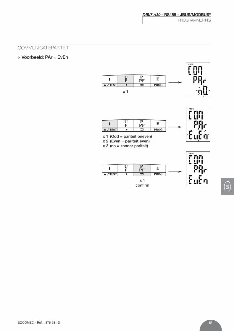
COMMUNICATIEPARITEIT
> Voorbeeld: PAr = EvEn
PROG/ TEST
x 1
PROG/ TEST
x 1 (Odd = pariteit oneven)x 2 (Even = pariteit even)x 3 (no = zonder pariteit)
PROG/ TEST
x 1confirm

DIRIS A20 - RS485 - JBUS/MODBUS®
66 SOCOMEC - Réf. : 876 581 D
DIRIS A20 - RS485 - JBUS/MODBUS®
PROGRAMMERING
COMMUNICATIE-STOPBIT> Voorbeeld: stop = 2
PROG/ TEST
x 1
PROG/ TEST
x 1 (2 bits)x 2 (1 bit)
PROG/ TEST
x 1confirm

67SOCOMEC - Réf. : 876 581 D
NL
LIJST VAN TE VISUALISEREN PARAMETERS (FUNCTIE 3)
Tabel van de toegewezen waarden van de transformatieverhoudingen stroom en spanning op 2 woorden
Decimaal Hexa. Aantal Aanduiding Eenheidadres adres woorden768 300 2 stroom fase 1 mA770 302 2 stroom fase 2 mA772 304 2 stroom fase 3 mA774 306 2 stroom van de nul mA776 308 2 samengestelde spanning U12 V/100778 30A 2 samengestelde spanning U23 V/100780 30C 2 samengestelde spanning U31 V/100782 30E 2 enkelvoudige spanning 1 V/100784 310 2 enkelvoudige spanning 2 V/100786 312 2 enkelvoudige spanning 3 V/100788 314 2 frequentie Hz/100790 316 2 Σ actief vermogen kW/100792 318 2 Σ reactief vermogen kvar/100794 31A 2 Σ schijnbaar vermogen kVA/100796 31C 2 Σ vermogensfacto
- : capacitief en + : inductief 0,001798…839 31E…347 Gereserveerde fabrikant838 346 2 I1 max gemiddeld mA840 348 2 I2 max gemiddeld mA842 34A 2 I3 max gemiddeld mA844 34C 2 Σ Actief vermogen + max kW/100846…855 34E…357 Gereserveerde fabrikant856 358 2 actieve energie + kWh858 35A 2 reactieve energie + kvarh860…915 35C…393 Gereserveerde fabrikant 916 394 2 In max gemiddeld mA
DIRIS A20 communiceert vanaf het protocolJBUS/MODBUS® hetgeen een dialoog impliceert vol-gens de structuur meester/slaaf. Twee dialogen zijnmogelijk:• de meester houdt een dialoog met een slaaf (DIRIS)
en wacht op zijn antwoord.• de meester houdt een dialoog met alle slaven (DIRIS)
zonder op hun antwoord te wachten.
De communicatiemodus is de RTU-modus (RemoteTerminal Unit) met hexadecimale tekens minimaalbestaande uit 8 bits.
Overeenkomstig het protocol JBUS/MODBUS® moetde tussentekentijd lager zijn dan 3 stiltes d.w.z. dande emissietijd van drie tekens om de boodschap telaten behandelen door de CMV2.Om deze informatie te gebruiken is het onmisbaar omde functies te gebruiken:
3: voor het lezen van n woorden (maximaal 128).6: voor het schrijven van een woord.8: voor de diagnose van de uitwisselingen tussen
meester en slaaf vanaf de tellers 1, 3, 4, 5 en 6.16: voor het schrijven van n woorden (maximaal 128).
Nota: Door het adres van de slaaf 0 te selecteren, zendt meneen boodschap aan alle apparaten op het net (alleenvoor de functies 6 en 16).
HET STRAMIEN VAN STANDAARDCOMMUNICATIE
Adres van de slaaf Code van de functie Adres Data CRC 16
DIRIS A20 - RS485 - JBUS/MODBUS®
COMMUNICATIE
Bestaat uit:

68 SOCOMEC - Réf. : 876 581 D
DIRIS A20 - RS485 - JBUS/MODBUS®
COMMUNICATIE
Tabel van de niet toegewezen waarden van de transformatieverhoudingen stroom en spanning op 1 woord
LIJST VAN TE VISUALISEREN PARAMETERS (FUNCTIE 3)Tabel van de niet toegewezen waarden van de transformatieverhoudingen stroom en spanning op 1 woord
Decimaal Hexa. Aantal Aanduiding Eenheidadres adres woorden2816 B00 1 stroom fase 1 mA2817 B01 1 stroom fase 2 mA2818 B02 1 stroom fase 3 mA2819 B03 1 stroom van de nul mA2820 B04 1 samengestelde spanning U12 V/1002821 B05 1 samengestelde spanning U23 V/1002822 B06 1 samengestelde spanning U31 V/1002823 B07 1 enkelvoudige spanning 1 V/1002824 B08 1 enkelvoudige spanning 2 V/1002825 B09 1 enkelvoudige spanning 3 V/1002826 B0A 1 frequentie Hz/1002827 B0B 1 Σ actief vermogen kW/1002828 B0C 1 Σ reactief vermogen kvar/1002829 B0D 1 Σ schijnbaar vermogen kVA/1002830 B0E 1 Σ vermogensfacto
- : capacitief en + : inductief 0,0012831 B0F 1 I1 max gemiddeld mA2832 B10 1 I2 max gemiddeld mA2833 B11 1 I3 max gemiddeld mA2834 B12 1 In max gemiddeld mA2835 B13 1 Σ actief vermogen + max gemiddeld kW/1002836 B14 1 actieve energie + < 10 000 kWh2837 B15 1 actieve energie + > 10 000 kWh2838 B16 1 reactieve energie + < 10 000 kvarh2839 B17 1 reactieve energie + > 10 000 kvarh
Decimaal Hexa. Aantal Aanduiding Eenheidadres adres woorden1792 700 1 stroom fase 1 mA1793 701 1 stroom fase 2 mA1794 702 1 stroom fase 3 mA1795 703 1 stroom van de nul mA1796 704 1 samengestelde spanning U12 V/1001797 705 1 samengestelde spanning U23 V/1001798 706 1 samengestelde spanning U31 V/1001799 707 1 enkelvoudige spanning 1 V/1001800 708 1 enkelvoudige spanning 2 V/1001801 709 1 enkelvoudige spanning 3 V/1001802 70A 1 frequentie Hz/1001803 70B 1 Σ actief vermogen kW/1001804 70C 1 Σ reactief vermogen kvar/1001805 70D 1 Σ schijnbaar vermogen kVA/1001806 70E 1 Σ vermogensfacto
- : capacitief en + : inductief 0,0011807…1826 710…722 Gereserveerde fabrikant 1827 723 1 I1 max gemiddeld mA1828 724 1 I2 max gemiddeld mA1829 725 1 I3 max gemiddeld mA1830 726 1 Σ actief vermogen + max gemiddeld kW/1001831…1834 727…72A Gereserveerde fabrikant1835 72B 1 actieve energie + < 10 000 kWh1836 72C 1 actieve energie + > 10 000 kWh1837 72D 1 reactieve energie+ < 10 000 kvarh1838 72E 1 reactieve energie + > 10 000 kvarh1389…1890 72F…762 Gereserveerde fabrikant 1891 763 1 In max gemiddeld mA

69SOCOMEC - Réf. : 876 581 D
DIRIS A20 - RS485 - JBUS/MODBUS®
NL
DIRIS A20 - RS485 - JBUS/MODBUS®
COMMUNICATIE
LIJST VAN TE VISUALISEREN PARAMETERS (FUNCTIE 3)Graad van harmonische vervorming
Decimaal Hexa. Aantal Aanduiding Eenheidadres adres woorden2304 900 1 thd I1 0,1%2305 901 1 thd I2 0,1%2306 902 1 thd I3 0,1%2307 903 1 Gereserveerde fabrikant2308 904 1 thd U12 0,1%2309 905 1 thd U23 0,1%2310 906 1 thd U31 0,1%2311 907 1 thd V1 0,1%2312 908 1 thd V2 0,1%2313 909 1 thd V3 0,1%

DIRIS A20 - RS485 - JBUS/MODBUS®
COMMUNICATIE
70 SOCOMEC - Réf. : 876 581 D
Decimaal Hexa. Aantal Aanduiding Eenheidadres adres woorden256 100 1 0 : geen optie
1 : optie meting2 : optie communicatie /
257 101 / Gereserveerde fabrikant258 102 1 Optie slot 1
0xFF : geen optie0x0 : optie meting0x1 : optie communicatie /
259 103 1 Optie slot 20xFF : ageen optie0x0 : optie meting0x1 : optie communicatie /
LIJST VAN TE VISUALISEREN PARAMETERS (FUNCTIE 3)Tabel van herkenning van de opties
Nota : als er meerdere opties worden gebruikt, is hetnodig het overeenkomstig cijfer aan de optie toe tevoegen.
Voorbeeld: Meting + communicatie komt overeen met het cijfer3,d.w.z. 1 + 2.

71SOCOMEC - Réf. : 876 581 D
DIRIS A20 - RS485 - JBUS/MODBUS®
COMMUNICATIE
NL
Decimaal Hexa. Aantal Aanduiding Eenheidadres adres woorden512 200 1 Netwerktype:
0 : 1BL1 : 2BL2 : 3BL3 : 3NBL4 : BL5 : 4NBL /
513 201 1 Secundaire van de TC:5 : 5A A
514 202 1 Primaire van de TC A515…518 203…206 Gereserveerde fabrikant519 207 1 Synchronisatie van I MAX :
2 : 2 sec.5 : 5 minuten8 : 8 minuten10 : 10 minuten15 : 15 minuten20 : 20 minuten30 : 30 minuten60 : 60 minuten /
520 208 1 Synchronisatie van P MAX :2 : 2 sec.5 : 5 minuten8 : 8 minuten10 : 10 minuten15 : 15 minuten20 : 20 minuten30 : 30 minuten60 : 60 minuten /
521 209 1 Toewijzing van OUT :0 : kWh +1 : kvarh + /
LIJST VAN TE VISUALISEREN OF TE CONFIGUREREN PARAMETERS (FUNCTIES 3, 6 EN 16)

DIRIS A20 - RS485 - JBUS/MODBUS®
72 SOCOMEC - Réf. : 876 581 D
DIRIS A20 - RS485 - JBUS/MODBUS®
COMMUNICATIE
Decimaal Hexa. Aantal Aanduiding Eenheidadres adres woorden1024 400 1 R.A.Z de :
Max 4I : 0x1Max P+ : 0x2kWh+ : 0x80kvarh+ : 0x100alle parameters: 0x1000 /
RESET VAN ENERGIETELLERS EN MAX. WAARDEN (FUNCTIE 6)
LIJST VAN TE VISUALISEREN OF TE CONFIGUREREN PARAMETERS (FUNCTIES 3, 6 EN 16)
522 20A 1 Gewicht van pulsen OUT :0 : 0,1 kWh/kvarh1 : 1 kWh/kvarh2 : 10 kWh/kvarh3 : 100 kWh/kvarh4 : 1000 kWh/kvarh5 : 10000 kWh/kvarh /
523 20B 1 Duur van pulsen OUT :1 : 100 ms2 : 200 ms3 : 300 ms4 : 400 ms5 : 500 ms6 : 600 ms7 : 700 ms8 : 800 ms9 : 900 ms /
Decimaal Hexa. Aantal Aanduiding Eenheidadres adres woorden
Slaaf
05
Functie
06
AdresZwaargewicht
02
AdresLichtgewicht
00
WaardenZwaargewicht
00
WaardenLichtgewicht
05
CRC 16
49F5
Voorbeeld:Configuratie van een onevenwichtig 4 draden net(4 NBL) voor de DIRIS nummer 5.
Antwoord van de DIRIS A20 : Identiek aan gezondenboodschap
Nota:Om meerdere parameters te resetten is het nodig hetovereenkomstige cijfer in de kolom “aanduiding” toete voegen.
Voorbeeld:Reset van Max P+ en kvarh +: 2 + 100 = 102 (hex)
Antwoord van de DIRIS A20 : Identiek aan gezondenboodschap
Slaaf
05
Functie
06
AdresZwaargewicht
04
AdresLichtgewicht
00
WaardenZwaargewicht
01
WaardenLichtgewicht
02
CRC 16
092F

73SOCOMEC - Réf. : 876 581 D
DIRIS A20 - RS485 - JBUS/MODBUS®
NL
DIRIS A20 - RS485 - JBUS/MODBUS®
COMMUNICATIE / TECHNISCHE EIGENSCHAPPEN
COMMUNICATIE
BEWAARCOMMANDO (RESET)
Om na wijziging de programmeringsparameters op teslaan in DIRIS nummer 5 is het nodig dit commandouit te voeren.
Nota :De DIRIS A20 antwoordt niet op dit commando.
Slaaf
05
Functie
06
AdresZwaargewicht
06
AdresLichtgewicht
00
Waarde
0000
CRC 16
88C6
TECHNISCHE EIGENSCHAPPEN
RS485 2 of 3 draden half duplexProtocol JBUS/MODBUS® modus RTUSnelheid van 2400 tot 38400 BaudsGalvanische isolatie 2,5 kV
LEXICON VAN DE AFKORTINGEN
COM Communicatie ADR Adres van de slaafBDS Communicatiesnelheid in baudPAR Pariteit van het communicatieframeNO Zonder pariteitEven OnevenOdd Oneven pariteitSTOP Stopbit1 1 stopbit2 2 stopbits
UL - CSA APPROVAL
Standard UL 61010-1CSA-C22.2 No. 61010-1
Certificate UL file No: E257746CSA report No. for DIRIS A20: 1810571CSA report No. for DIRIS A40: 1810577

DIRIS A20 - RS485 - JBUS/MODBUS®
74 SOCOMEC - Réf. : 876 581 D
DIRIS A20 - RS485 - JBUS/MODBUS®
OPERACIONES PREVIAS
Funciones El módulo opcional de comunicación IP se debe asociara los modelos DIRIS A20 (ref. 4825 0A20). Pone a dis-posición un enlace serie RS485 (2 o 3 hilos) en proto-colo JBUS/MODBUS® que permite la puesta en ser-vicio del DIRIS A20 a partir de un PC o de un API.
GenaralidadesEn una configuración estándar, mediante una conexiónRS 485 se pueden interconectar 31 DIRIS A20 con unPC o un autómata situado como máximo a 1500metros, mediante el protocolo JBUS/MODBUS®.
N 1 N 2 N n R = 120
1200 M
R = 120
Autómatasprogramables
Otros sistemas
N 1 R = 120
Autómatasprogramables
Otros sistemas
repetidor
RS485
0+- -+0 N n
R = 120
1200 M 1200 M
DIR
IS 1
09 E
ES
PD
IRIS
110
E E
SP
Recomendaciones:Será necesario utilizar un par blindado tipo LIYCY. Enun entorno perturbado o en una red importante en lon-gitud y en número de Diris, aconsejamos utilizar un parblindado tipo con un blindaje general tipo LIYCY-CY. Si la distancia es mayor que 1200 m y/o el número deDiris es superior a 31, será necesario instalar un repe-tidor (1 vía) o un amplificador (4 vías) para la instala-ción adicional de Diris A20, para más de 1200 m.
Para mayor información sobre la metodología deconexión, agradeceremos nos consulten.Nota: En los 2 extremos de la unión, será indispensable utilizarla resistencia de 120 ohms que se encuentra en elmódulo adicional.
Existen otras soluciones (módem,TCP-IP, fibra óptica...).Rogamos nos consulten.
Para la seguridad del personal y del material, será impe-rativo conocer perfectamente el contenido de estemanual antes de su puesta en funcionamiento.Al recibir el paquete que contiene el DIRIS A20, seránecesario verificar los aspectos siguientes:• estado del embalaje;• que el producto no se haya dañado durante el
transporte;
• que la referencia del aparato esté conforme con supedido;
• el embalaje incluye el producto el manual de utilización.
INFORMACIONES GENERALES

75SOCOMEC - Réf. : 876 581 D
E
DIRIS A20 - RS485 - JBUS/MODBUS®
INSTALACIÓN
CONEXIÓN
El módulo se instala en la cara trasera del DIRIS A20 en uno de los dos emplazamientos previstos para ello.
DIR
IS 3
42 A
DIR
IS 3
43 A
ON1
ON1
0V - +R=120Ω
DIR
IS 3
47 A
�
�
�Fije el módulo en uno de los dos emplazamientos
�Conexionar respetando las indicacionesPoner en tensión
El DIRIS A20 deberá estar desconectado

DIRIS A20 - RS485 - JBUS/MODBUS®
76 SOCOMEC - Réf. : 876 581 D
DIRIS A20 - RS485 - JBUS/MODBUS®
PROGRAMACIÓN
Menú anterior
Menú siguiente
PROG/ TEST
PROG/ TEST
PROG/ TEST
PROG/ TEST
PROG/ TEST
p.67
p.68
p.69
p.70
77SOCOMEC - Réf. : 876 581 D
DIRIS A20 - RS485 - JBUS/MODBUS®
E
DIRIS A20 - RS485 - JBUS/MODBUS®
PROGRAMACIÓN
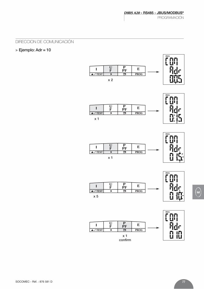
DIRECCION DE COMUNICACIÓN
> Ejemplo: Adr = 10
PROG/ TEST
x 2
PROG/ TEST
x 1
PROG/ TEST
x 1
PROG/ TEST
PROG/ TEST
x 1confirm
x 5

DIRIS A20 - RS485 - JBUS/MODBUS®
78 SOCOMEC - Réf. : 876 581 D
DIRIS A20 - RS485 - JBUS/MODBUS®
PROGRAMACIÓN
VELOCIDAD DE COMUNICACIÓN
> Ejemplo: bds = 38,4 kbauds
PROG/ TEST
x 1
PROG/ TEST
x 1 (19,2 kbauds)x 2 (38,4 kbauds)x 3 (2,4 kbauds)x 4 (4,8 kbauds)x 5 (9,6 kbauds)
PROG/ TEST
x 1confirm

79SOCOMEC - Réf. : 876 581 D
DIRIS A20 - RS485 - JBUS/MODBUS®
E
DIRIS A20 - RS485 - JBUS/MODBUS®
PROGRAMACIÓN
PARIDAD DE COMUNICACIÓN
> Ejemplo: PAr = EvEn
PROG/ TEST
x 1
PROG/ TEST
x 1 (Odd = paridad impar)x 2 (Even = paridad uniforme)x 3 (no = ningún paridad)
PROG/ TEST
x 1confirm

DIRIS A20 - RS485 - JBUS/MODBUS®
80 SOCOMEC - Réf. : 876 581 D
DIRIS A20 - RS485 - JBUS/MODBUS®
PROGRAMACIÓN
BIT DE STOP DE COMUNICACIÓN> Ejemplo: stop = 2
PROG/ TEST
x 1
PROG/ TEST
x 1 (2 bits)x 2 (1 bit)
PROG/ TEST
x 1confirm

81SOCOMEC - Réf. : 876 581 D
DIRIS A20 - RS485 - JBUS/MODBUS®
E
LISTA DE PARÁMETROS A VISUALIZAR (FUNCIÓN 3)
Tabla de valores atribuidos de los informes de transformación de intensidad y de tensión en dos palabrasDirección Dirección Número Texto UnidadDecimal hexa. de palabras768 300 2 intensidad fase 1 mA770 302 2 intensidad fase 2 mA772 304 2 intensidad fase 3 mA774 306 2 intensidad del neutro mA776 308 2 tensión compuesta U12 V/100778 30A 2 tensión compuesta U23 V/100780 30C 2 tensión compuesta U31 V/100782 30E 2 tensión simple fase 1 V/100784 310 2 tensión simple fase 2 V/100786 312 2 tensión simple fase 3 V/100788 314 2 frecuencia Hz/100790 316 2 Σ potencia activa kW/100792 318 2 Σ potencia reactiva kvar/100794 31A 2 Σ potencia aparente kVA/100796 31C 2 Σ factor de potencia
- : capacitivo e + : inductivo 0,001798…839 31E…347 Fabricante reservado 838 346 2 I1 medio mA840 348 2 I2 medio mA842 34A 2 I3 medio mA844 34C 2 Σ potencia activa + max kW/100846…855 34E…357 Fabricante reservado 856 358 2 energía activa + kWh858 35A 2 energía reactiva + kvarh860…915 35C…393 Fabricante reservado 916 394 2 In medio mA
DIRIS A20 comunica a partir de un protocoloJBUS/MODBUS® que implica un diálogo según unaestructura maestra/esclava. Son posibles dos diálogos:• el diálogo maestro con un esclavo (DIRIS y espera
de respuesta• el diálogo maestro con todos los esclavos (DIRIS) sin
espera de respuesta.
El modo de comunicación es el modo RTU (Remoteterminal Unit) con caracteres hexadecimales compuestosde 8 bits como mínimo.
Conforme al protocolo JBUS/MODBUS®, el tiempointercarácter deberá ser inferior a 3 silencios, es deciral tiempo de emisión de tres caracteres para que elmensaje se trate por el CMV2.Para utilizar correctamente la información seráindispensable utilizar las funciones:
3: para la lectura de n palabras (máximo 128).6: para le escritura de un palabra.8: para el diagnóstico de intercambios entre el maestro y
el esclavo a partir de los contadores 1, 3, 4, 5 y 6.16: para la escritura de n palabras (máximo 128).
Nota:Al seleccionar la dirección del esclavo 0, se transmiteun mensaje a todos les aparatos presentes en la red(únicamente para las funciones 6 y 16).
LA TRAMA DE COMUNICACIÓN ESTANDÁR
Dirección del esclavo Código de la función Dirección Datos CRC 16
DIRIS A20 - RS485 - JBUS/MODBUS®
COMUNICACIÓN
Está compuesta de:

82 SOCOMEC - Réf. : 876 581 D
DIRIS A20 - RS485 - JBUS/MODBUS®
COMUNICACIÓN
Tabla de valores no atribuidos de informes de transformación intensidad y tensión en 1 palabra
LISTA DE PARÁMETROS A VISUALIZAR (FUNCIÓN 3)
Tabla de valores no atribuidos de informes de transformación intensidad y tensión en 1 palabra
Dirección Dirección Número Texto UnidadDecimal hexa. de palabras2816 B00 1 intensidad fase 1 mA2817 B01 1 intensidad fase 2 mA2818 B02 1 intensidad fase 3 mA2819 B03 1 intensidad del neutro mA2820 B04 1 tensión compuesta U12 V/1002821 B05 1 tensión compuesta U23 V/1002822 B06 1 tensión compuesta U31 V/1002823 B07 1 tensión simple fase 1 V/1002824 B08 1 tensión simple fase 2 V/1002825 B09 1 tensión simple fase 3 V/1002826 B0A 1 frecuencia Hz/1002827 B0B 1 Σ potencia activa kW/1002828 B0C 1 Σ potencia reactiva kvar/1002829 B0D 1 Σ potencia aparente kVA/1002830 B0E 1 Σ factor de potencia
- : capacitivo e + : inductivo 0,0012831 B0F 1 I1 max medio mA2832 B10 1 I2 max medio mA2833 B11 1 I3 max medio mA2834 B12 1 In max medio mA2835 B13 1 Σ potencia reactiva + máximo medio kW/1002836 B14 1 energía activa + < 10 000 kWh2837 B15 1 energía activa + > 10 000 kWh2838 B16 1 energía reactiva + < 10 000 kvarh2839 B17 1 energía reactiva + > 10 000 kvarh
Dirección Dirección Número Texto UnidadDecimal hexa. de palabras1792 700 1 intensidad fase 1 mA1793 701 1 intensidad fase 2 mA1794 702 1 intensidad fase 3 mA1795 703 1 intensidad del neutro mA1796 704 1 tensión compuesta U12 V/1001797 705 1 tensión compuesta U23 V/1001798 706 1 tensión compuesta U31 V/1001799 707 1 tensión simple fase 1 V/1001800 708 1 tensión simple fase 2 V/1001801 709 1 tensión simple fase 3 V/1001802 70A 1 frecuencia Hz/1001803 70B 1 Σ potencia activa kW/1001804 70C 1 Σ potencia reactiva kvar/1001805 70D 1 Σ potencia aparente kVA/1001806 70E 1 Σ factor de potencia
- : capacitivo e + : inductivo 0,0011807…1826 710…722 Fabricante reservado1827 723 1 I1 medio mA1828 724 1 I1 medio mA1829 725 1 I1 medio mA1830 726 1 Σ potencia reactiva + máximo medio kW/1001831…1834 727…72A Fabricante reservado1835 72B 1 energía activa + < 10 000 kWh1836 72C 1 energía activa+ > 10 000 kWh1837 72D 1 energía reactiva + < 10 000 kvarh1838 72E 1 energía reactiva+ > 10 000 kvarh1839…1890 72F…762 Fabricante reservado1891 763 1 In medio mA

83SOCOMEC - Réf. : 876 581 D
DIRIS A20 - RS485 - JBUS/MODBUS®
E
DIRIS A20 - RS485 - JBUS/MODBUS®
COMUNICACIÓN
LISTA DE PARAMETROS A VISUALIZAR (FUNCIÓN 3)Tabla de distorsión armónico
Dirección Dirección Número Texto UnidadDecimal hexa. de palabras2304 900 1 thd I1 0,1%2305 901 1 thd I2 0,1%2306 902 1 thd I3 0,1%2307 903 1 Fabricante reservado2308 904 1 thd U12 0,1%2309 905 1 thd U23 0,1%2310 906 1 thd U31 0,1%2311 907 1 thd V1 0,1%2312 908 1 thd V2 0,1%2313 909 1 thd V3 0,1%

DIRIS A20 - RS485 - JBUS/MODBUS®
COMUNICACIÓN
84 SOCOMEC - Réf. : 876 581 D
Dirección Dirección Número Texto UnidadDecimal hexa. de palabras256 100 1 0 : ninguna opción
1 : opción recuento2 : opción comunicación /
257 101 / Fabricante reservado258 102 1 Opción slot 1
0xFF : ninguna opción0x0 : opción recuento0x1 : opción comunicación /
259 103 1 Opción slot 20xFF : aninguna opción0x0 : opción recuento0x1 : opción comunicación /
LISTA DE PARÁMETROS A VISUALIZAR (FUNCIÓN 3)Tabla de reconocimiento de opciones
Nota: si se utilizan varias opciones, se deberá adicionarel número correspondiente a la opción.
Ejemplo: recuento + comunicación corresponderá alnúmero 3, es decir 1 + 2.

85SOCOMEC - Réf. : 876 581 D
DIRIS A20 - RS485 - JBUS/MODBUS®
COMUNICACIÓN
E
Dirección Dirección Número Texto UnidadDecimal hexa. de palabras512 200 1 Tipo de red:
0 : 1BL1 : 2BL2 : 3BL3 : 3NBL4 : 4BL5 : 4NBL /
513 201 1 Secundaria del TC :5 : 5A A
514 202 1 Primaria del TC A515…518 203…206 Fabricante reservado519 207 1 Sincronización de I MAX :
2 : 2 sec.5 : 5 minutos8 : 8 minutos10 : 10 minutos15 : 15 minutos20 : 20 minutos30 : 30 minutos60 : 60 minutos /
520 208 1 Sincronización de P MAX :2 : 2 sec.5 : 5 minutos8 : 8 minutos10 : 10 minutos15 : 15 minutos20 : 20 minutos30 : 30 minutos60 : 60 minutos /
521 209 1 atribución de OUT :0 : kWh +1 : kvarh + /
LISTA DE PARÁMETROS A VISUALIZAR O A CONFIGURAR (FUNCIONES 3, 6 Y 16)

DIRIS A20 - RS485 - JBUS/MODBUS®
86 SOCOMEC - Réf. : 876 581 D
DIRIS A20 - RS485 - JBUS/MODBUS®
COMUNICACIÓN
Dirección Dirección Número Texto UnidadDecimal hexa. de palabras1024 400 1 R.A.Z de :
Max 4I : 0x1Max P+ : 0x2kWh+ : 0x80kvarh+ : 0x100todos los parámetros: 0x1000 /
PUESTA EN CERO DE LOS CONTADORES DE ENERGIA Y DE LOS VALORES MAXS. (FUNCIÓN 6)
LISTA DE PARÁMETROS A VISUALIZAR O A CONFIGURAR (FUNCIONES 3, 6 Y 16)
522 20A 1 peso de impulsos OUT :0 : 0,1 kWh/kvarh1 : 1 kWh/kvarh2 : 10 kWh/kvarh3 : 100 kWh/kvarh4 : 1000 kWh/kvarh5 : 10000 kWh/kvarh /
523 20B 1 duración de impulsos OUT :1 : 100 ms2 : 200 ms3 : 300 ms4 : 400 ms5 : 500 ms6 : 600 ms7 : 700 ms8 : 800 ms9 : 900 ms /
Dirección Dirección Número Texto UnidadDecimal hexa. de palabras
Esclavo
05
Función
06
DirecciónPeso alto
02
DirecciónPeso bajo
00
ValorPeso alto
00
ValorPeso bajo
05
CRC 16
49F5
Ejemplo:Configuración de una red 4 hilos no equilibrada (4 NBL)para el DIRIS numéro 5.
Respuesta del DIRIS A20 : Idéntica al mensaje enviado
Nota:Para la puesta a cero de varios parámetros, es necesarioadicionar la cifra correspondiente indicada en lacolumna “Texto”
Ejemplo: Puesta a cero de Max P+ y de kvarh +: 2+100=102(hex.)
Respuesta del DIRIS A20 : Idéntica al mensaje enviado
Esclavo
05
Función
06
DirecciónPeso alto
04
DirecciónPeso bajo
00
ValorPeso alto
01
ValorPeso bajo
02
CRC 16
092F

87SOCOMEC - Réf. : 876 581 D
DIRIS A20 - RS485 - JBUS/MODBUS®
E
DIRIS A20 - RS485 - JBUS/MODBUS®
COMUNICACIÓN / CARACTERISTÍCAS TÉCNICAS
COMMUNICACIÓN
COMANDO GUARDAR (RESET
Tras modificar los parámetros de programación ypara guardarlos en el DIRIS número 5 será necesariorealizar este comando.
Nota: El DIRIS A20 no responde a este comando.
Esclavo
05
Función
06
DirecciónPeso alto
06
DirecciónPeso bajo
00
Valor
0000
CRC 16
88C6
CARACTERÍSTICAS TÉCNICAS
RS485 2 o 3 hilo half dúplexProtocolo JBUS/MODBUS® modo RTUVelocidad de 2400 a 38400 BaudiosAislamientio galvánico 2,5 kV
LEXICO DE LAS ABREVIACIONES
COM Comunicación ADR Dirección del esclavoBDS Velocidad de comunicación en baudiosPAR Paridad de la trama de comunicaciónNO Sin paridadEven Paridad parOdd Paridad imparSTOP Bip de stop1 1 bit de stop2 2 bits de stop
UL - CSA APPROVAL
Norma UL 61010-1CSA-C22.2 No. 61010-1
Certificado No de expediente UL: E257746No de informe CSA DIRIS A20: 1810571No de informe CSA DIRIS A40: 1810577

DIRIS A20 - RS485 - JBUS/MODBUS®
88 SOCOMEC - Réf. : 876 581 D
DIRIS A20 - RS485 - JBUS/MODBUS®
OPERAÇÕES PRELIMINARES
Funções O módulo opção Comunicação IP deve estar associa-do aos DIRIS A2 (ref. 4825 0A20). Coloca à sua dispo-sição uma ligação de série RS485 (2 ou 3 fios) em pro-tocolo JBUS/MODBUS® que permite a exploração doDIRIS A20 a partir de um PC ou de um API.
Generalidades Numa configuração padrão, uma ligação RS 485 permi-te colocar em ligação 31 DIRIS A20 o COUNTIS Ci comum PC ou um autómato a uma distância de 1500 metrosa partir do protocolo JBUS/MODBUS®.
N 1 N 2 N n R = 120
1200 M
R = 120
CLP's
Outros sistemas
N 1 R = 120
CLP's
Outros sistemas
repetidore
RS485
0+- -+0 N n
R = 120
1200 M 1200 M
DIR
IS 1
09 E
PD
IRIS
110
E P
Recomendações:É necessário utilizar um par torcido blindado tipo LIY-CY. Num ambiente perturbado ou numa rede impor-tante em comprimento e em número de Diris, convémutilizar um par torcido blindado com uma blindagemgeral tipo LIYCY-CY.Se a distância de 1200 m e/ou o número de 31 DIRIS sãoultrapassados, é necessário ligar um repetidor (1 via) ouum amplificador (4 vias) para permitir uma ligaçãosuplementar de DIRIS A20 em mais de 1200 m. Para
mais informações sobre a metodologia de ligação éfavor consultar-nos.
Nota:Nas 2 extremidades da ligação, é indispensável fixaruma resistência de 120 ohms que se encontra nomódulo.Outras soluções existentes (modem, TCP-IP, fibraóptica...).É favor consultar-nos.
Nota:Para a segurança do pessoal e do material,convém inteirar-se bem do conteúdo deste manualantes da colocação em serviço.Na altura da recepção da encomenda do DIRIS A20,é necessário verificar os seguintes pontos:
• o estado da embalagem;• se o produto não foi danificado durante o transporte;• se a referência do Aparelho está acordo com a sua
encomenda;• dentro da embalagem encontra-se realmente o
produto e um manual de utilização.
INFORMAÇÕES GERAIS

89SOCOMEC - Réf. : 876 581 D
P
DIRIS A20 - RS485 - JBUS/MODBUS®
INSTALAÇÃO
LIGAÇÃO
O módulo instalase na face traseira do DIRIS A20 numa das 2 localizações.
DIR
IS 3
42 A
DIR
IS 3
43 A
ON1
ON1
0V - +R=120Ω
DIR
IS 3
47 A
�
�
�Fixe o módulo numa das 2 localizações
�Ligar o terminal de bornes respeitando as indicações Colocar sob tensão novamente
O DIRIS A20 deve ficar desligado

DIRIS A20 - RS485 - JBUS/MODBUS®
90 SOCOMEC - Réf. : 876 581 D
DIRIS A20 - RS485 - JBUS/MODBUS®
PROGRAMAÇÃO
Menu precedente
Menu seguir
PROG/ TEST
PROG/ TEST
PROG/ TEST
PROG/ TEST
PROG/ TEST
p.79
p.80
p.81
p.82

91SOCOMEC - Réf. : 876 581 D
DIRIS A20 - RS485 - JBUS/MODBUS®
P
DIRIS A20 - RS485 - JBUS/MODBUS®
PROGRAMAÇAO
ENDEREÇO DA COMUNICAÇÃO
> Exemplo: Adr = 10
PROG/ TEST
x 2
PROG/ TEST
x 1
PROG/ TEST
x 1
PROG/ TEST
PROG/ TEST
x 1confirm
x 5

DIRIS A20 - RS485 - JBUS/MODBUS®
92 SOCOMEC - Réf. : 876 581 D
DIRIS A20 - RS485 - JBUS/MODBUS®
PROGRAMAÇÃO
VELOCIDADE DE COMUNICAÇÃO
> Exemplo: bds = 38,4 kbauds
PROG/ TEST
x 1
PROG/ TEST
x 1 (19,2 kbauds)x 2 (38,4 kbauds)x 3 (2,4 kbauds)x 4 (4,8 kbauds)x 5 (9,6 kbauds)
PROG/ TEST
x 1confirm

93SOCOMEC - Réf. : 876 581 D
DIRIS A20 - RS485 - JBUS/MODBUS®
P
DIRIS A20 - RS485 - JBUS/MODBUS®
PROGRAMAÇAO
PARIDADE DE COMUNICAÇÃO
> Exemplo: PAr = EvEn
PROG/ TEST
x 1
PROG/ TEST
x 1 (Odd = paridade ímpar)x 2 (Even = paridade igual)x 3 (no = sem paridade)
PROG/ TEST
x 1confirm
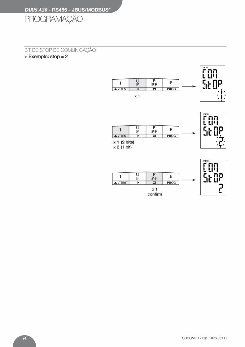
DIRIS A20 - RS485 - JBUS/MODBUS®
94 SOCOMEC - Réf. : 876 581 D
DIRIS A20 - RS485 - JBUS/MODBUS®
PROGRAMAÇÃO
BIT DE STOP DE COMUNICAÇÃO> Exemplo: stop = 2
PROG/ TEST
x 1
PROG/ TEST
x 1 (2 bits)x 2 (1 bit)
PROG/ TEST
x 1confirm

95SOCOMEC - Réf. : 876 581 D
P
LISTA DOS PARÁMETROS A VISUALIZAR (FUNÇÃO 3)
Tabela dos valores afectados dos relatórios de transformação corrente e tensão em 2 palavras.Endereço Endereço Número de Significado UnidadeDecimal hexa. palavras768 300 2 corrente fase 1 mA770 302 2 corrente fase 2 mA772 304 2 corrente fase 3 mA774 306 2 corrente do neutro mA776 308 2 tensão composta U12 V/100778 30A 2 tensão composta U23 V/100780 30C 2 tensão composta U31 V/100782 30E 2 tensão simples fase 1 V/100784 310 2 tensão simples fase 2 V/100786 312 2 tensão simples fase 3 V/100788 314 2 frequência Hz/100790 316 2 Σ potência activa kW/100792 318 2 Σ potência reactiva kvar/100794 31A 2 Σ potência aparente kVA/100796 31C 2 Σ factor de potência
- : capacitivo e + : indutivo 0,001798…839 31E…347 Reservado fabricante 838 346 2 I1 max medio mA840 348 2 I2 max medio mA842 34A 2 I3 max medio mA844 34C 2 Σ potência activa + max kW/100846…855 34E…357 Reservado fabricante 856 358 2 energia activa + kWh858 35A 2 energia reactiva + kvarh860…915 35C…393 Reservado fabricante 916 394 2 In max medio mA
O DIRIS A20 comunica a partir de um protocoloJBUS/MODBUS® que implica um diálogo medianteuma estrutura mestre/escravo. Dois diálogos sãopossíveis:• o mestre diáloga com um escravo (DIRIS) e aguarda
a sua resposta• o mestre diáloga com todos os escravos (DIRIS) sem
aguardar a sua resposta.
O modo de comunicação é o modo RTU (Remote terminal Unit) com caracteres hexadecimais constituído,no mínimo, de 8 bits.
Em conformidade com o protocolo JBUS/MODBUS®,o tempo inter-caracter deve ser inferior a 3 silêncios,isto é ao tempo de emissão de três caracteres paraque a mensagem seja tratada pelo CMV2.Para explorar correctamente as informações, éindispensável utilizar as funções:
3: para a leitura de n palavras (máximo 128).6: para a redacção de uma palavra.8: para o diagnóstico das trocas entre o mestre e o
escravo a partir dos contadores 1, 3, 4, 5 e 6.16: para a redacção de n palavras (máximo 128).
Nota:Seleccionando o endereço do escravo 0, transmite-seuma mensagem a todos os aparelhos apresentadosna rede (apenas para as funções 6 e 16).
A TRAMA DE COMUNICAÇÃO PADRAO
Endereço do escravo Código da função Endereço Dados CRC 16
DIRIS A20 - RS485 - JBUS/MODBUS®
COMUNICAÇÃO
é constituída por:

96 SOCOMEC - Réf. : 876 581 D
DIRIS A20 - RS485 - JBUS/MODBUS®
COMUNICAÇÃO
Tabela dos valores afectados dos relatórios de transformação corrente e tensão numa palavra
LISTA DOS PARAMETROS A VISUALIZAR (FUNÇAO 3)Tabela dos valores afectados dos relatórios de transformação corrente e tensão numa palavra
Endereço Endereço Número de Significado UnidadeDecimal hexa. palavras2816 B00 1 corrente fase 1 mA2817 B01 1 corrente fase 2 mA2818 B02 1 corrente fase 3 mA2819 B03 1 corrente do neutro mA2820 B04 1 tensão composta U12 V/1002821 B05 1 tensão composta U23 V/1002822 B06 1 tensão composta U31 V/1002823 B07 1 tensão simples fase 1 V/1002824 B08 1 tensão simples fase 2 V/1002825 B09 1 tensão simples fase 3 V/1002826 B0A 1 frequência Hz/1002827 B0B 1 Σ potência activa kW/1002828 B0C 1 Σ potência reactiva kvar/1002829 B0D 1 Σ potência aparente kVA/1002830 B0E 1 Σ factor de potência
- : capacitivo e + : indutivo 0,0012831 B0F 1 I1 max medio mA2832 B10 1 I2 max medio mA2833 B11 1 I3 max medio mA2834 B12 1 In max medio mA2835 B13 1 valor médio Σ potência reactiva + kW/1002836 B14 1 energia activa + < 10 000 kWh2837 B15 1 energia activa + > 10 000 kWh2838 B16 1 energia reactiva + < 10 000 kvarh2839 B17 1 energia reactiva + > 10 000 kvarh
Endereço Endereço Número de Significado UnidadeDecimal hexa. palavras1792 700 1 corrente fase 1 mA1793 701 1 corrente fase 2 mA1794 702 1 corrente fase 3 mA1795 703 1 corrente do neutro mA1796 704 1 tensão composta U12 V/1001797 705 1 tensão composta U23 V/1001798 706 1 tensão composta U31 V/1001799 707 1 tensão simples fase 1 V/1001800 708 1 tensão simples fase 2 V/1001801 709 1 tensão simples fase 3 V/1001802 70A 1 frequência Hz/1001803 70B 1 Σ potência activa kW/1001804 70C 1 Σ potência reactiva kvar/1001805 70D 1 Σ potência aparente kVA/1001806 70E 1 Σ factor de potência
- : capacitivo e + : indutivo 0,0011807…1826 710…722 Reservado fabricante 1827 723 1 I1 max medio mA1828 724 1 I2 max medio mA1829 725 1 I3 max medio mA1830 726 1 valor médio Σ potência reactiva + kW/1001831…1834 727…72A Reservado fabricante 1835 72B 1 energia activa + < 10 000 kWh1836 72C 1 energia activa + > 10 000 kWh1837 72D 1 energia reactiva + < 10 000 kvarh1838 72E 1 energia reactiva + > 10 000 kvarh1839…1890 72F…762 Reservado fabricante 1891 763 1 In max medio mA

97SOCOMEC - Réf. : 876 581 D
DIRIS A20 - RS485 - JBUS/MODBUS®
P
DIRIS A20 - RS485 - JBUS/MODBUS®
COMUNICAÇÃO
LISTA DOS PARAMETROS A VISUALIZAR (FUNÇÃO 3)Tabela de grau de distorcão harmonicã
Endereço Endereço Número de Significado UnidadeDecimal hexa. palavras2304 900 1 thd I1 0,1%2305 901 1 thd I2 0,1%2306 902 1 thd I3 0,1%2307 903 1 Reservado fabricante2308 904 1 thd U12 0,1%2309 905 1 thd U23 0,1%2310 906 1 thd U31 0,1%2311 907 1 thd V1 0,1%2312 908 1 thd V2 0,1%2313 909 1 thd V3 0,1%

DIRIS A20 - RS485 - JBUS/MODBUS®
COMUNICAÇÃO
98 SOCOMEC - Réf. : 876 581 D
Endereço Endereço Número de Significado UnidadeDecimal hexa. palavras256 100 1 0 : nenhuma opção
1 : opção contagem2 : opção comunicação /
257 101 / Reservado fabricante 258 102 1 Opção slot 1
0xFF : nenhuma opção0x0 : opção contagem0x1 : opção comunicação /
259 103 1 Opção slot 20xFF : nenhuma opção0x0 : opção contagem0x1 : opção comunicação /
LISTA DOS PARÁMETROS A VISUALIZAR (FUNÇÃO 3)Tabela de reconhecimento das opções
Nota : se utilizar várias opções, é necessário adicionaro número correspondente à opção.
Exemplo: contagem + comunicação corresponderá aonúmero 3, ou seja 1 + 2.

99SOCOMEC - Réf. : 876 581 D
DIRIS A20 - RS485 - JBUS/MODBUS®
COMUNICAÇÃO
P
Endereço Endereço Número de Significado UnidadeDecimal hexa. palavras512 200 1 Tipo de rede:
0 : 1BL1 : 2BL2 : 3BL3 : 3NBL4 : 4BL5 : 4NBL /
513 201 1 Secundário do TC :5 : 5A A
514 202 1 Primário do TC A515…518 203…206 Reservado fabricante 519 207 1 Sincronização de I MAX :
2 : 2 sec.5 : 5 minutos8 : 8 minutos10 : 10 minutos15 : 15 minutos20 : 20 minutos30 : 30 minutos60 : 60 minutos /
520 208 1 Sincronização de P MAX :2 : 2 sec.5 : 5 minutos8 : 8 minutos10 : 10 minutos15 : 15 minutos20 : 20 minutos30 : 30 minutos60 : 60 minutos /
521 209 1 Afectação de OUT :0 : kWh +1 : kvarh + /
LISTA DOS PARÁMETROS A VISUALIZAR OU A CONFIGURAR (FUNÇÕES 3, 6 E 16)

DIRIS A20 - RS485 - JBUS/MODBUS®
100 SOCOMEC - Réf. : 876 581 D
DIRIS A20 - RS485 - JBUS/MODBUS®
COMUNICAÇÃO
Endereço Endereço Número de Significado UnidadeDecimal hexa. palavras1024 400 1 R.A.Z de :
Max 4I : 0x1Max P+ : 0x2kWh+ : 0x80kvarh+ : 0x100todos os parâmetros: 0x1000 /
COLOCAÇÃO A ZERO DOS CONTADORES DE ENERGIAS E DOS VALORES MÁX. (FUNÇÃO 6)
LISTA DOS PARÁMETROS A VISUALIZAR OU A CONFIGURAR (FUNÇÕES 3, 6 E 16)
522 20A 1 Peso dos impulsos OUT :0 : 0,1 kWh/kvarh1 : 1 kWh/kvarh2 : 10 kWh/kvarh3 : 100 kWh/kvarh4 : 1000 kWh/kvarh5 : 10000 kWh/kvarh /
523 20B 1 Duração dos impulsos OUT :1 : 100 ms2 : 200 ms3 : 300 ms4 : 400 ms5 : 500 ms6 : 600 ms7 : 700 ms8 : 800 ms9 : 900 ms /
Endereço Endereço Número de Significado UnidadeDecimal hexa. palavras
Escravo
05
Função
06
Endereço Peso forte
02
Endereço Peso fraco
00
ValorPeso forte
00
ValorPeso fraco
05
CRC 16
49F5
Exemplo:Configuração de uma rede 4 fios não equilibrado(4 NBL) para o Diris número 5.
Resposta do DIRIS A20 : Idêntico à mensagem enviada
Nota :Para remeter a zero vários parâmetros, é necessárioadicionar o número correspondente indicado nacolona “Significado”.
Exemplo:Colocação a zero de Max P+ e kvarh+: 2 + 100 = 102(Hex)
Resposta do DIRIS A20 : Idêntico à mensagem enviada
Escravo
05
Função
06
Endereço Peso forte
04
Endereço Peso fraco
00
ValorPeso forte
01
ValorPeso fraco
02
CRC 16
092F

101SOCOMEC - Réf. : 876 581 D
DIRIS A20 - RS485 - JBUS/MODBUS®
P
DIRIS A20 - RS485 - JBUS/MODBUS®
COMUNICAÇÃO / CARACTERÍSTICAS TÉCNICAS
COMUNICAÇÃO
COMANDO SALVAGUARDA (RESET)
Após ter modificado os parâmetros de programação epara os guardar, é necessário realizar este comando.
Nota :O DIRIS A20 não responde a este comando.
Escravo
05
Função
06
Endereço Peso forte
06
Endereço Peso fraco
00
Valor
0000
CRC 16
88C6
CARACTERÍSTICAS TÉCNICAS
RS485 2 ou 3 fios half duplexProtocolo JBUS/MODBUS® modo RTUVelocidade de 2400 a 38400 BaudsIsolamento galvânico 2,5 kV
LEXICO DAS ABREVIATURAS
COM Comunicação ADR Endereço do escravoBDS Velocidade de comunicação em baudsPAR Paridade da trama de comunicaçãoNO Sem paridadeEven Paridade parOdd Paridade ímparSTOP Bip de stop da trama1 1 bit de stop2 2 bits de stop
UL - CSA APPROVAL
Standard UL 61010-1CSA-C22.2 No. 61010-1
Certificate UL file No: E257746CSA report No. for DIRIS A20: 1810571CSA report No. for DIRIS A40: 1810577


SOCOMEC - Ref.: 876 581 D - 012/07
This document is not a contract. SOCOMEC reserves the right to modify features without prior notice in view of continued improvement.
H E A D O F F I C ESOCOMEC GROUPS.A. capital 11 065 700 €R.C. Strasbourg 548500 149 B1, Rue de Westhouse - B.P. 60010 - F-67235 Benfeld Cedex - FRANCE
I N T E R N A T I O N A LS A L E S D E P A R T M E N TSOCOMEC1, rue de Westhouse - B.P. 60010F - 67235 Benfeld Cedex - FRANCETél. +33 (0)3 88 57 41 41 - Fax +33 (0)3 88 74 08 [email protected]
www.socomec.com
DIR
IS 3
45 A
/ Q
UAT
NO
T 3i