rt530e-2 - crane rental · pdf file7 r t 5 3 0 e-2 rt530e-2 load chart this chart is only a...
TRANSCRIPT

productguide
features
• 30 ton (27 mt)capacity
• 29 ft. - 95 ft. (8.8 m -29.0 m) 4-section full power boom
• 26 ft. - 45 ft. (7.9 m - 13.7 m) offsettable telescopic swing-away extension
• Dual-axis electric joystick controllers
• Full frame decking
• Rounded cab design
• 160 hp (119 kw) Cummins dieselengine (tier III)
RT530E-2
Rough Terrain Hydraulic Crane
contentsFeatures 2
Specifications 3
Dimensions 5
Working Range 6
Load Charts 7
2
features
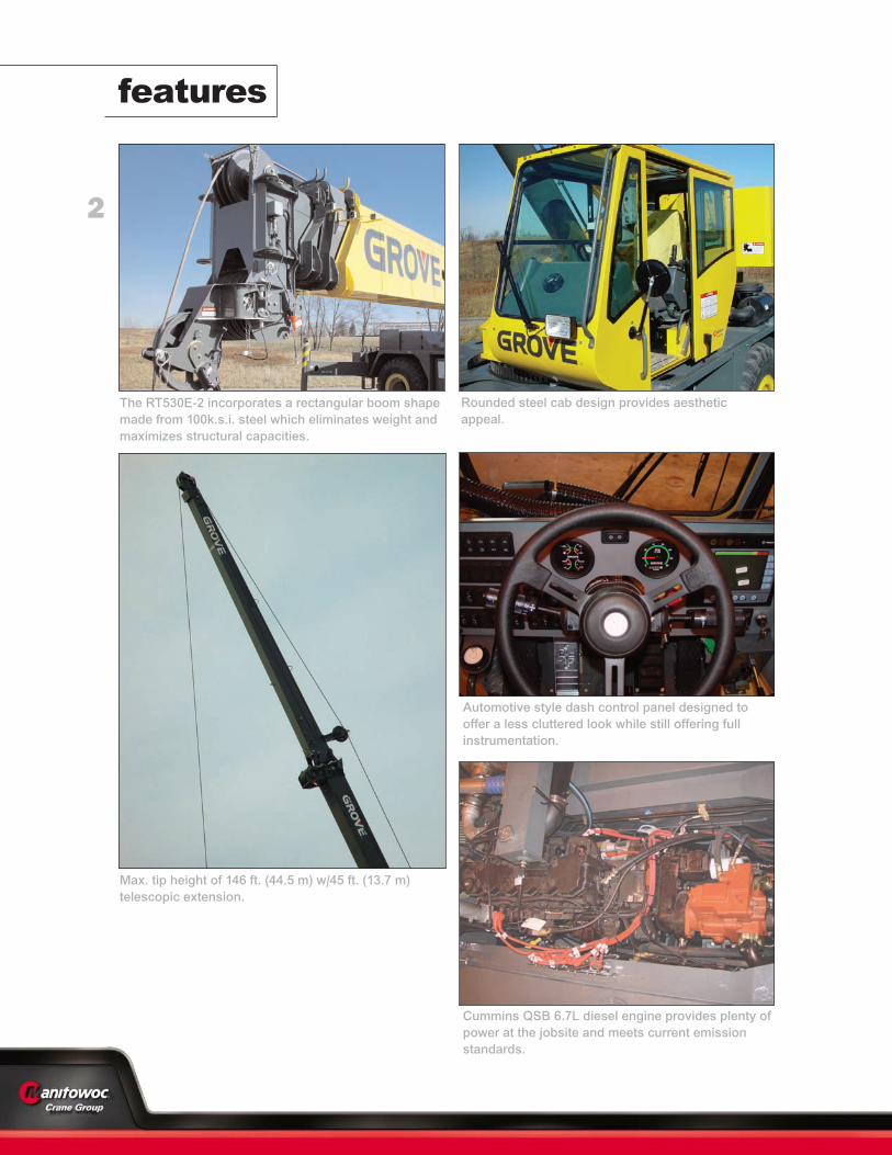
Cummins QSB 6.7L diesel engine provides plenty ofpower at the jobsite and meets current emissionstandards.
Automotive style dash control panel designed tooffer a less cluttered look while still offering fullinstrumentation.
Rounded steel cab design provides aestheticappeal.
The RT530E-2 incorporates a rectangular boom shapemade from 100k.s.i. steel which eliminates weight andmaximizes structural capacities.
Max. tip height of 146 ft. (44.5 m) w/45 ft. (13.7 m) telescopic extension.

3
RT530
E-2
specifications
Superstructure
Boom29 ft. - 95 ft. (8.8 m - 29.0 m) four-section, synchronized fullpower boom. Maximum tip height: 102.5 ft. (31.2 m).
*Optional Fixed Swingaway Extension26 ft. (7.9 m) offsettable swingaway extension. Offsets at 0° and30°. Stows alongside base boom section. Maximum tip height: 127.6 ft. (38.9 m).
*Optional Telescopic Swingaway Extension26 ft. - 45 ft. (7.9 m - 13.7 m) offsettable telescopic latticeswingaway extension. Offsets at 0° and 30°. Stows alongsidebase boom section.Maximum tip height: 146 ft. (44.5 m).
Boom NoseThree nylatron sheaves mounted on heavy duty tapered rollerbearings with removable pin-type rope guards. Quick reeve typeboom nose.
Boom ElevationOne double-acting hydraulic cylinder with integralholding valve provides elevation from -3° to +76°.
Load Moment & Anti-Two Block SystemStandard “Graphic Display” load moment and anti-two blocksystem with audio-visual warning and control lever lockout.These systems provide electronic display of boom angle, length,radius, tip height, relative load moment, maximum permissibleload, load indication and warning of impending two-blockcondition. The standard Work Area Definition System allows theoperator to pre-select and define safe working areas. If thecrane approaches the pre-set limits, audio-visual warnings aidthe operator in avoiding job-site obstructions.
CabFull vision, all steel fabricated with acoustical lining and tintedsafety glass throughout. Deluxe seat incorporates armrest-mounted electric dual-axis controllers. Dash panel incorporates gauges for all engine functions. Other standard features include: tilt steering wheel, hot waterheater, cab circulating air fan, sliding side and rear windows,sliding skylight with electric wiper and sunscreen, electricwindshield wash/wipe, fire extinguisher and seat belt.
SwingSingle speed, planetary swing drive with foot applied multi-discwet brake. Spring applied, hydraulically released swing brake.Single position mechanical house lock, operated from cab.Maximum speed: 2.0 RPM.
Counterweight8,416 lbs. (3 817 kg) pinned to superstructure.
Hydraulic SystemTwo main pumps ([1] piston and [1] gear) with a combinedcapacity of 83.6 GPM (316.5 LPM).Maximum operating pressure: 4,000 psi (275.7 bar).Three section pressure compensated valve bank. Return linetype filter with full flow by-pass protection and service indicator.Replaceable cartridge with micron filtration rating of 5/12/16.104.6 gallon (396 L) hyd. reservoir. System pressure test ports.
HOIST SPECIFICATIONS (HP15C-17G)Main and Auxiliary HoistPlanetary reduction with automatic spring applied multi-disc wetbrake. Electronic hoist drum rotation indicators, and hoist drumcable followers.
Maximum Single Line Pull:1st layer: 11,640 lbs. (5 280 kg)3rd layer: 9,530 lbs. (4 323 kg)5th layer: 8,060 lbs. (3 656 kg)
Maximum Permissible Line Pull:11,640 lb. (5 280 kg.) with 6x37 class rope11,640 lb. (5 280 kg.) with 35x7 class rope
Maximum Single Line Speed: 445 FPM (136 m/min)
Rope Construction:6x36 EIPS IWRC, Special Flexible35x7 Flex-X, Rotation Resistant
Rope Diameter:5/8 in. (16 mm)
Rope Length:Main Hoist 450 ft. (137.0 m)Auxillary Hoist 450 ft. (137.0 m)
Maximum Rope Stowage:596 ft. (181 m)
*Denotes optional equipment
B
B
C

4
RT530
E-2
specifications
Carrier
ChassisBox section frame fabricated from high-strength, low alloy steel.
Front/rear towing and tie down lugs.
Outrigger SystemFour hydraulic telescoping single-stage double box beam
outriggers with inverted jacks and integral holding valves.
Three position setting, 0%, 50% and fully extended. All steel
fabricated quick release type outrigger floats, 14.25 in. (362 mm)
square.
Maximum outrigger pad load: 54,800 lbs. (24 857 kg)
Outrigger ControlsControls and crane level indicator located in cab.
Engine (Tier III)Cummins QSB 6.7L diesel, six cylinders, 160 bhp (119 kW)(Gross) @ 2,500 RPM.
Maximum torque: 540 ft. lb. (732 Nm) @ 1,500 RPM.
Fuel Tank Capacity58 gallons (219 L)
TransmissionRange-shift 6 speed (3 speeds x 2 range, both forward &
reverse).
Front axle disconnect for 4 x 2 travel.
Electrical SystemTwo 12 V - maintenance free batteries. 12 V starting and lighting. Battery disconnect.CanBus Diagnosticsystem.
Drive4 x 4
SteeringFully independent power steering:
Front: Full hydraulic steering wheel controlled.
Rear: Full hydraulic switch controlled.
Provides infinite variations 4 main steering modes: front only,
rear only, crab and coordinated.
Rear steer indicator.
Outside turning radius: 19.1 ft. (5.8m)
Inside turning radius: 13.1 ft. (4.0m)
AxlesFront: Drive/steer with differential and planetary reduction
hubs rigid mounted to frame.
Rear: Drive/steer with differential and planetary reduction
hubs pivot mounted to frame.
Oscillation LockoutsAutomatic full hydraulic lockouts on rear axle permits 10 in. (25.4
cm) oscillation only with boom centered over the front.
BrakesFull hydraulic split circuit disc-type brakes operating on all
wheels. Spring-applied, hydraulically released parking brake
mounted on front axle.
TiresStd. 20.5 x 25 - 24 bias ply
Option: 16.0 x 25-28 bias ply
LightsFull lighting including turn indicators, head, tail, brake and
hazard warning lights.
Maximum Speed25 MPH (40 kph) @ 2500 r.p.m.
Gradeability (Theoretical)119% (at engine stall)
(Based on 59,537 lb. [27 006 kg] GVW) 20.5 x 25 tires, 95 ft.
(29.0m) main boom, plus 45 ft. (13.7m) telescopic swingaway,
8,416 lb. (3 817 kg) counterweight, 30T (27mt) hookblock and
7.5 T (6.8mt) headache ball.
Miscellaneous Standard EquipmentFull width steel fenders, full length steel decking with anti-skid,
dual rear view mirrors, hook-block tiedown, electronic back-up
alarm, light package, front stowage well, tachometer/hourmeter,
rear wheel position indicator, 36,000 Btu hot water cab heater,
hoist mirrors, engine distress A/V warning system, front/rear tie
down and tow lugs, coolant sight level indicator.
*Optional Equipment* AUXILIARY HOIST PACKAGE (includes Model HP15C-17Gauxiliary hoist with electronic hoist drum rotation indicator, hoistdrum cable follower, 450 ft. (137.0 m) of 5/8 in. (16 mm) 35 x 7class wire rope and auxiliary single sheave boom nose.*AUXILIARY LIGHTING PACKAGE (includes S/S mounted amberflashing light and dual base boom mounted halogen floodlights).*LMI light bar (in cab)*Air conditioning (28,500 BTU)*360 degree NYC style mechanical swing lock*Rear Pintle hook*Cab-controlled cross axle differential locks (front & rear)*PAT Data logger down-load kit*Rubber mat for stowage trough
*Denotes optional equipment
F
O
L


6
RT530
E-2
45' EXT.
26' EXT.
95
90
80
70
60
50
40
29
160
150
140
130
120
110
100
90
80
70
60
50
40
30
20
10
0
Operating radius in feet from axis of rotation
76°MAX.BOOMANGLE
AXIS OFROTATION
140 120 100 80 60 40 20130 110 90 70 50 30 10
0° OFFSET
30° OFFSET
0°
10°
20°
30°
40°
50°
60°
70°
8' - 2" 7' - 8" Dimensions are for largest Grove furnished hookblock and headache ball, with anti-two block activated.
R [ft]
Hei
ght f
rom
the
grou
nd in
feet
Boo
m a
nd e
xten
sion
leng
th in
feet
H [ft]
working range
Working range – 95 ft. Main Boom + 26-45 ft. extension
THIS CHART IS ONLY A GUIDE AND SHOULD NOT BE USED TO OPERATE THE CRANE. The individual crane’s load chart, operating instructions andother instructional plates must be read and understood prior to operating the crane.

7
RT530
E-2
RT530E-2 load chart
THIS CHART IS ONLY A GUIDE AND SHOULD NOT BE USED TO OPERATE THE CRANE. The individual crane’s load chart, operating instructions andother instructional plates must be read and understood prior to operating the crane.
Pounds
29-95 ft. 8,416 lbs 100%20' spread
360º
Feet 29 40 50 60 70 80 90 95
10 60,000(60.5)
50,100(69.5)
46,950(74.5)
12 54,650(56)
50,100(66.5)
44,950(72)
*38,850(76)
15 42,850(47.5)
43,800(61.5)
41,050(68)
36,000(72)
*29,450(76)
*22,450(76)
20 30,700(30)
31,650(53)
32,100(61.5)
29,500(67)
27,400(71)
22,450(73.5)
*18,550(76)
*15,500(76)
25 24,050(42.5)
24,500(54.5)
24,800(61.5)
23,100(66.5)
19,250(70)
16,500(72.5)
15,300(74)
30 18,800(29)
19,250(47)
19,550(56)
19,600(61.5)
16,850(66)
14,400(69)
13,200(70.5)
35 15,550(38)
15,850(49.5)
16,000(56.5)
14,850(61.5)
12,700(65.5)
11,500(67.5)
40 12,800(26)
12,950(42.5)
13,000(51.5)
13,050(57.5)
11,000(62)
10,000(64)
45 10,450(34.5)
10,500(46)
10,550(53)
9,630(58.5)
9,060(60.5)
50 8,610(23.5)
8,630(39.5)
8,670(48)
8,720(54.5)
7,990(57)
55 7,170(32)
7,200(43)
7,250(50)
7,100(53)
60 6,000(22)
6,030(37)
6,100(45.5)
6,110(49)
65 5,080(30)
5,120(40.5)
5,150(44.5)
70 4,270(20.5)
4,330(35)
4,350(40)
75 3,650(28.5)
3,700(34.5)
80 3,100(20)
3,100(28)
85 2,600(20)
Minimum boom angle (°) for indicated length (no load) 0Maximum boom length (ft.) at 0° boom angle (no load) 95NOTE: ( ) Boom angles are in degrees.#LMI operating code. Refer to LMI manual for operating instructions.*This capacity is based on maximum boom angle.
Lifting Capacities at Zero Degree Boom AngleOn Outriggers Fully Extended - 360°
BoomAngle
Main Boom Length in Feet29 40 50 60 70 80 90 95.2
0 deg. 26,100(22.8)
15,800(33.8)
11,000(43.8)
7,430(53.8)
5,220(63.8)
3,730(73.8)
2,660(83.8)
2,220(89)
A6-829-101755NOTE: ( ) Reference radii in feet.

8
RT530
E-2
RT530E-2 load chart
THIS CHART IS ONLY A GUIDE AND SHOULD NOT BE USED TO OPERATE THE CRANE. The individual crane’s load chart, operating instructions andother instructional plates must be read and understood prior to operating the crane.
Pounds
29-95 ft. 26-45 ft. 8,416 lbs 100% 360º
Feet
**26 ft. LENGTH 45 ft. LENGTH
#0021 #0023 #0041 #00430°
OFFSET30°
OFFSET0°
OFFSET30°
OFFSET
30 *8,200(76)
35 8,200(73.5)
*5,250(76)
40 8,200(71)
*5,780(76)
5,250(75)
45 8,120(68.5)
5,780(73.5)
4,940(73)
50 7,350(66)
5,360(71)
4,540(71)
55 6,370(63)
4,750(68)
4,150(68.5)
*2,730(76)
60 5,670(60.5)
4,290(65)
3,890(66)
2,730(74.5)
65 4,820(57.5)
3,870(62)
3,740(64)
2,730(72)
70 4,200(54.5)
3,530(59)
3,600(61.5)
2,580(69.5)
75 3,680(51.5)
3,230(56)
3,470(59)
2,520(67)
80 3,080(48.5)
3,000(52.5)
3,240(56.5)
2,460(64)
85 2,520(45)
2,780(49)
3,050(54)
2,420(61.5)
90 2,050(41)
2,410(45)
2,820(51)
2,390(58.5)
95 1,670(37)
1,970(40.5)
2,480(48.5)
2,370(55.5)
100 1,370(32.5)
1,580(35.5)
2,090(45.5)
2,310(52)
105 1,020(27.5)
1,740(42)
2,000(49)
110 1,430(38.5)
1,580(45)
115 1,150(35)
1,260(40.5)
120 900(30.5)
Min. boom anglefor indicated length
(no load) 24° 30° 30° 30°
Max. boom lengthat 0° boom angle
(no load) 80 ft. 80 ft.
A6-829-100272A#LMI operating code. Refer to LMI manual for instructions.*This capacity based on maximum boom angle.**26 ft. capacities are also applicable to fixed offsettable ext. However,the LMI codes will change to #0051 and #0053 for 0° and 30° offset,respectively.
Pounds
29-60 ft. 8,416 lbs Stationary 360º
Feet
#9005
Main Boom Length in Feet29 40 50 60
10 25,550(60.5)
25,550(70)
*16,450(76)
12 20,600(56)
20,600(66.5)
16,450(72)
15 14,350(47.5)
14,350(62)
14,350(68)
14,350(72.5)
20 8,280(30)
8,280(53)
8,280(61.5)
8,280(67)
25 5,330(42.5)
5,330(54.5)
5,330(61.5)
30 3,630(29)
3,630(47)
3,630(56)
35 2,500(38)
2,500(49.5)
40 1,690(26)
1,690(42.5)
45 1,090(34.5)
Min. boom angle for indicated length (no load) 34°Max. boom length at 0° boom angle (no load) 50 ft.
NOTE: ( ) Boom angles are in degrees.#LMI operating code. Refer to LMI manual for instructions.*This capacity is based upon maximum boom angle.
Lifting Capacity at Zero Degree On Rubber - 360°
BoomAngle
Main Boom Length in Feet
29 40 50
0° 6,110(22.8)
2,730(33.8)
1,210(43.8)
A6-829-100274CNOTE: Reference radii in feet.
Pounds
29-60 ft. 8,416 lbs
Stationary Defined ArcOver Front
Feet Main Boom Length in Feet29 40 50 60
10 30,100(60.5)
26,550(70)
16,450(74.5)
12 26,550(56)
22,100(66.5)
16,450(72)
15 22,100(47.5)
22,100(62)
16,450(68)
16,450(72.5)
20 16,050(30)
16,050(53)
16,050(61.5)
16,050(67)
25 11,005(42.5)
11,005(54.5)
11,005(61.5)
30 8,060(29)
8,060(47)
8,060(56)
35 6,110(38)
6,110(49.5)
40 4,720(26)
4,720(42.5)
45 3,680(34.5)
50 2,870(23.5)
Min. boom angle for indicated length (no load) 0°Max. boom length at 0° boom angle (no load) 60 ft.
NOTE: ( ) Boom angles are in degrees.#LMI operating code. Refer to LMI manual for instructions.
Lifting Capacity at Zero Degree On Rubber
BoomAngle
Main Boom Length in Feet
29 40 50 60
0° 12,700(22.8)
6,500(33.8)
3,890(43.8)
2,360(53.8)
A6-829-100275BNOTE: Reference radii in feet.
Stationary- Defined Arc Boom Centered Over Front
#9005
BOOM EXTENSION CAPACITY NOTES:1. All capacities above the bold line are based on structural strength of boom extension.2. 26 ft. and 45 ft. boom extension lengths may be used for single line lifting service.3. Radii listed are for a fully extended boom with the boom extension erected. For main
boom lengths less than fully extended, the rated loads are determined by boom angle.Use only the column which corresponds to the boom extension length and offset forwhich the machine is configured. For boom angles not shown, use the rating of the nextlower boom angle.WARNING: Operation of this machine with heavier loads than the capacities listed isstrictly prohibited. Machine tipping with boom extension occurs rapidly and withoutadvance warning.
4. Boom angle is the angle above or below horizontal of the longitudinal axis of the boombase section after lifting rated load.
5. Capacities listed are with outriggers fully extended and vertical jacks set only.

RT530E-2 load charts
9
RT530
E-2
THIS CHART IS ONLY A GUIDE AND SHOULD NOT BE USED TO OPERATE THE CRANE. The individual crane’s load chart, operating instructions andother instructional plates must be read and understood prior to operating the crane.
NOTES TO ALL RUBBER CAPACITY CHARTS:
1. Capacities are in pounds and do not exceed 75% of tipping loads as determined bytest in accordance with SAE J765.
2. Capacities are applicable to machines equipped with 20.5x25 (24 ply) tires at 75 psicold inflation pressure, and 16.00x25 (28 ply) tires at 100 psi cold inflation pressure.
3. Defined Arc - Over front includes 6° on either side of longitudinal centerline of machine(ref. drawing C6-829-003529).
4. Capacities appearing above the bold line are based on structural strength and tippingshould not be relied upon as a capacity limitation.
5. Capacities are applicable only with machine on firm level surface.
6. On rubber lifting with boom extensions not permitted.
7. For pick and carry operation, boom must be centered over front of machine,mechanical swing lock engaged and load restrained from swinging. When handlingloads in the structural range with capacities close to maximum ratings, travel should bereduced to creep speeds.
8. Axle lockouts must be functioning when lifting on rubber.
9. All lifting depends on proper tire inflation, capacity and condition. Capacities must bereduced for lower tire inflation pressures. See lifting capacity chart for tire used.Damaged tires are hazardous to safe operation of crane.
10. Creep - Not over 200 ft. of movement in any 30 minute period and not exceeding 1 mph.
Pounds
29-60 ft. 8,416 lbs
Pick & Carry(Max. 2.5 MPH)20.5 x 25 Tires
Boom CenteredOver Front
Feet Main Boom Length in Feet29 40 50 60
10 25,900(60.5)
25,900(70)
18,250(74.5)
12 22,350(56)
22,350(66.5)
18,250(72)
15 18,250(47.5)
18,250(62)
18,250(68)
13,350(72.5)
20 13,350(30)
13,350(53)
13,350(61.5)
13,350(67)
25 10,350(42.5)
10,350(54.5)
10,350(61.5)
30 8,060(29)
8,060(47)
8,060(56)
35 4,810(38)
4,810(49.5)
40 3,770(26)
3,770(42.5)
45 2,930(34.5)
50 2,240(23.5)
Min. boom angle for indicated length (no load) 0°Max. boom length at 0° boom angle (no load) 60 ft.
NOTE: ( ) Boom angles are in degrees.#LMI operating code. Refer to LMI manual for instructions.
BoomAngle
Main Boom Length in Feet
29 40 50 60
0° 11,400(22.8)
5,090(33.8)
3,110(43.8)
1,800(53.8)
A6-829-100276BNOTE: Reference radii in feet.
Lifting Capacity at Zero Degree On RubberPick & Carry - Boom Centered Over Front
#9006
Pounds
29-95 ft. 8,416 lbs
50%14 ft. spread
360º
Feet
#4001
Main Boom Length in Feet
29 40 50 60 70 80 90 95
10 60,000(60.5)
48,000(69.5)
45,000(74.5)
12 53,300(56)
48,000(66.5)
44,950(72)
*37,000(76)
15 42,100(47.5)
40,500(61.5)
38,350(68)
36,000(72)
*27,400(76)
*21,000(76)
20 23,950(30)
23,850(53)
23,900(61.5)
24,050(67)
23,200(71)
21,000(73.5)
*17,000(76)
*15,500(76)
25 15,850(42.5)
15,950(54.5)
16,150(61.5)
16,350(66.5)
16,400(70)
15,950(72.5)
15,300(74)
30 11,350(29)
11,500(47)
11,650(56)
11,800(61.5)
12,000(66)
12,150(69)
12,100(70.5)
35 8,620(38)
8,820(49.5)
8,930(56.5)
9,050(61.5)
9,190(65.5)
9,260(67.5)
40 6,610(26)
6,820(42.5)
6,900(51.5)
6,990(57.5)
7,100(62)
7,150(64)
45 5,350(34.5)
5,400(46)
5,470(53)
5,550(58.5)
5,600(60.5)
50 4,220(23.5)
4,260(39.5)
4,310(48)
4,370(54.5)
4,410(57)
55 3,350(32)
3,390(43)
3,430(50)
3,460(53)
60 2,600(22)
2,640(37)
2,670(45.5)
2,700(49)
65 2,020(30)
2,050(40.5)
2,060(44.5)
70 1,490(20.5)
1,520(35)
1,530(40)
75 1,070(28.5)
1,080(34.5)
0.1A (lb.) 660 610 580 560 550 540 540 530Minimum boom angle (°) for indicated length (no load) 15 20Maximum boom length (ft.) at 0° boom angle (no load) 80NOTE: ( ) Boom angles are in degrees.#LMI operating code. Refer to LMI manual for operating instructions.*This capacity is based on maximum boom angle.
Lifting Capacities at Zero Degree Boom AngleOn Outriggers 50% Extended - 360°
BoomAngle
Main Boom Length in Feet29 40 50 60 70 80
0 deg. 18,800(22.8)
9,000(33.8)
5,400(43.8)
3,480(53.8)
2,100(63.8)
1,130(73.8)
A6-829-100270ANOTE: ( ) Reference radii in feet.

10
RT530
E-2
load charts
THIS CHART IS ONLY A GUIDE AND SHOULD NOT BE USED TO OPERATE THE CRANE. The individual crane’s load chart, operating instructions andother instructional plates must be read and understood prior to operating the crane.
29-95 ft. 8,416 lbs
0%7 ft. 10 in. spread
360º
FeetMain Boom Length in Feet
29 40 50 60 70 80 90 95
10 34,700(60.5)
32,400(69.5)
30,400(74.5)
12 26,200(56)
25,400(66.5)
24,100(72)
*22,900(76)
15 17,750(47.5)
17,550(61.5)
17,550(68)
17,250(72)
*16,550(76)
*10,900(76)
20 10,650(30)
10,600(53)
10,650(61.5)
10,750(67)
11,000(71)
10,900(73.5)
*10,500(76)
*10,350(76)
25 6,930(42.5)
7,020(54.5)
7,170(61.5)
7,350(66.5)
7,560(70)
7,610(72.5)
7,490(74)
30 4,670(29)
4,780(47)
4,950(56)
5,080(61.5)
5,240(66)
5,390(69)
5,480(70.5)
35 3,270(38)
3,450(49.5)
3,550(56.5)
3,660(61.5)
3,780(65.5)
3,850(67.5)
40 2,170(26)
2,370(42.5)
2,440(51.5)
2,520(57.5)
2,620(62)
2,670(64)
45 1,550(34.5)
1,600(46)
1,660(53)
1,740(58.5)
1,780(60.5)
50 1,050(54.5)
1,080(57)
0.1A (lb) 660 610 580 560 550 540 540 530Minimum boom angle (°) for indicated
length (no load) 33 43 51 53 55Maximum boom length (ft.) at 0° boom
angle (no load) 50NOTE: ( ) Boom angles are in degrees.#LMI operating code. Refer to LMI manual for operating instructions.*This capacity is based on maximum boom angle.
Lifting Capacities at Zero Degree Boom AngleOn Outriggers 0% Extended - 360°
BoomAngle
Main Boom Length in Feet29 40 50
0 deg. 8,310(22.8)
3,390(33.8)
1,480(43.8)
NOTE: ( ) Reference radii in feet. A6-829-100271A
#8001
Pounds
BOOM EXTENSION CAPACITY NOTES:
1. All capacities above the bold line are based on structural strength of boom extension.
2. 26 ft. and 45 ft. boom extension lengths may be used for single line lifting service.
3. Radii listed are for a fully extended boom with the boom extension erected. For mainboom lengths less than fully extended, the rated loads are determined by boom angle.Use only the column which corresponds to the boom extension length and offset forwhich the machine is configured. For boom angles not shown, use the rating of thenext lower boom angle.
WARNING: Operation of this machine with heavier loads than the capacities listed isstrictly prohibited. Machine tipping with boom extension occurs rapidly and withoutadvance warning.
4. Boom angle is the angle above or below horizontal of the longitudinal axis of the boombase section after lifting rated load.
5. Capacities listed are with outriggers properly extended and vertical jacks set only.
Pounds
29-95 ft. 8,416 lbs
50%14 ft. spread
360º
NOTE: ( ) Boom angles are in degrees.
Feet
**26 ft. LENGTH 45 ft. LENGTH
#4021 #4023 #4041 #40430°
OFFSET30°
OFFSET0°
OFFSET30°
OFFSET
30 *8,200(76)
35 8,200(73.5)
*5,250(76)
40 6,940(71)
*5,780(76)
5,250(75)
45 5,580(68.5)
5,780(73.5)
4,940(73)
50 4,490(66)
5,360(71)
4,540(71)
55 3,600(63)
4,350(68)
4,150(68.5)
*2,730(76)
60 2,860(60.5)
3,430(65)
3,490(66)
2,730(74.5)
65 2,190(57.5)
2,670(62)
2,870(64)
2,730(72)
70 1,610(54.5)
2,030(59)
2,340(61.5)
2,580(69.5)
75 1,120(51.5)
1,490(56)
1,840(59)
2,520(67)
80 1,020(52.5)
1,400(56.5)
2,260(64)
85 1,020(54)
1,760(61.5)
90 1,310(58.5)
0.1A (lb.) 570 540 500 460Min. boom angle
for indicated length(no load) 44° 46° 48° 49°
Max. boom length at0° boom angle
(no load)60 ft. 60 ft.
#LMI operating code. Refer to LMI manual for instructions.*This capacity based on maximum boom angle.**26 ft. capacities are also applicable to fixed offsettable ext. However,the LMI codes will change to #4051 and #4053 for 0° and 30° offset,respectively.
A6-829-100273B
26-45 ft.

11
RT530
E-2
When lifting over swingaway and/or jib combinations, deduct total weight of allload handling devices reeved over main boom nose directly from swingawayor jib capacity.
NOTE: All load handling devices and boom attachments are considered part ofthe load and suitable allowances MUST BE MADE for their combined weights.Weights are for Grove furnished equipment.
load handling
Weight Reductions for Load Handling Devices
26 ft. Offsettable Boom Extension Pounds *Erected – 2,960
26 ft.-45 ft. Tele. Boom Extension Pounds*Erected (Retracted) – 4,220*Erected (Extended) – 5,780
*Reduction of main boom capacities
Auxiliary Boom Nose Pounds142
Hookblocks and Headache Balls Pounds30 Ton, 3 Sheave 580 +15 Ton, 2 Sheave 425 +7.5 Ton Overhaul Ball 354 +7.5 Ton Headache Ball 338 +
+Refer to rating plate for actual weight.
Permissible NominalHoists Cable Specs Line Pulls Cable Length
5/8" (16 mm) Flex-X35 (35x7)Main & Aux. Rotation Resistant (non-rotating) 11,640 lb. 450 ft.
Min. Breaking Str. 61,200 lb.
5/8" (16 mm) 6x37 ClassMain EIPS, IWRC Special Flexible 11,640 lb. 450 ft.
Min. Breaking Str. 41,200 lb.
Bold lines determine the limiting position of any load for operation within working areas indicated.
THIS CHART IS ONLY A GUIDE AND SHOULD NOT BE USED TO OPERATE THE CRANE. The individual crane’s load chart, operating instructions andother instructional plates must be read and understood prior to operating the crane.
Line Pulls and Reeving Information
Wire Hoist Line Drum RopeRope Pulls Capacity (ft.)Layer Available lb.* Layer Total
1 11,640 77 772 10,480 85 1623 9,530 94 2564 8,730 102 3585 8,060 111 4696 7,490 119 588
*Max. lifting capacity: 6x37 class = 11,640 lb.35x7 class = 11,640 lb.
Hoist Performance
Working Area Diagram
360°
360°OVER SIDE
OVER REAR
OVER SIDE
OVER FRONT
CENTERLINE OF ROTATION
SEE NOTE AT BOTTOM
LONGITUDINAL CENTERLINE
OF CRANE
CENTERLINE OF OUTRIGGER
SUPPORT
CENTERLINE OF BOOM
CG OF LOAD
LIFTING ON OUTRIGGERS
REAR AXLE OSCILLATION
LOCKOUTS MUST BE SET TO
MAINTAIN 360° CAPACITIES
C6-829-003529 C6-829-001159
BOLD LINES DETERMINE THE LIMITING POSITION OF ANY LOAD FOR OPERATION WITHIN WORKING AREAS INDICATED
6°12°
BOOM CENTERED
OVER FRONT
FRONT
LIFTING ON TIRES
DIAGRAM OF WORKING AREA
++

Constant improvement and engineering progress make it necessary that we reserve the right to makespecification, equipment, and price changes without notice. Illustrations shown may include optional equipmentand accessories, and may not include all standard equipment.
Manitowoc Crane Group - Americas
Manitowoc, Wisconsin FacilityTel: [Int + 001] 920 684 6621Fax: [Int + 001] 920 683 6277Shady Grove, Pennsylvania Facility Tel: [Int + 001] 717 597 8121Fax: [Int + 001] 717 597 4062Manitowoc Crane Group - EMEA
Europe Middle East & AfricaTel: [Int + 33] (0) 472 18 20 20Fax: [Int + 33] (0) 472 18 20 00 Manitowoc Crane Group - UK
Europe Middle East & AfricaTel: [Int + 44] (0) 191 565 6281Fax: [Int + 44] (0) 191 564 0442Manitowoc Crane Group - Germany
(Sales, Parts & Service) Tel: [Int + 49](0) 2173 8909 0Fax: [Int + 49] (0) 2173 8909-30Manitowoc Crane Group - France
France & Africa (Sales, Parts & Service)Tel: [Int + 33] (0) 1 303 13150 Fax: [Int + 33] (0) 1 303 86085Manitowoc Crane Group - Netherlands
(Sales, Parts & Service)Tel: [Int + 31] (0) 76 578 39 99 Fax: [Int + 31] (0) 76 578 39 78Manitowoc Crane Group - Italy
Italy & Southern Europe (Sales, Parts & Service)Tel: [Int + 39] (0) 331 49 33 11 Fax: [Int + 39] (0) 331 49 33 30Manitowoc Crane Group - Portugal
Portugal & Spain (Sales, Parts & Service)Tel: [Int + 351] (0) 22 968 08 89 Fax: [Int + 351] (0) 22 968 08 97Manitowoc Crane Group - Singapore
Asia/Pacific excl China (Sales, Parts & Service)Tel: [Int + 65] 6861 1733 Fax: [Int + 65] 6862 4040 / 4142Manitowoc Crane Group - Shanghai
China (Sales, Parts & Service)Tel: [Int + 86] (0) 21 64955555 Fax: [Int + 86] (0) 2164852038Manitowoc Crane Group - Beijing
China (Sales, Parts & Service)Tel: [Int + 86] (0) 10 646 71690Fax: [Int + 86] (0) 10 646 71691Manitowoc Crane Group - Middle East
(Sales)Tel: [Int + 971] (0) 4 348 4478Fax: [Int + 971] (0) 4 348 4478 (Parts & Service) Tel: [Int + 973] (0) 9 660 899Fax: [Int + 973] (0) 2 707 740
www.manitowoccranegroup.com
Distributed By:
107-2M Printed in USA Form No. RT530E-2 Part No. 07-002 Manitowoc Crane Group 2007