rt530e-2 product guide
TRANSCRIPT

Features
• 30 t (30 USt) capacity
• 8,8 m – 29 m (29 ft – 95 ft) four-section full- power boom
• 7,9 m – 13,7 m (26 ft – 45 ft) offsettable telescopic swingaway extension
• Intuitive, user friendly controls with electronic joysticks and operator customizable function speeds
• Full frame decking
• 122 kW (164 hp) Tier 4F Cummins diesel engine
RT530E-2 Product Guide
ASME B30.5Imperial 85%

GROVE RT530E-2
Boom shape The RT530E-2 incorporates a rectangular boom shape made from 100 ksi steel, which eliminates weight and maximizes structural capacities.
Crane Control System (CCS) The Crane Control System (CCS) offers a user friendly interface, two full graphic displays mounted vertically for easier viewing and a jog dial for easier navigation and data input. The system allows the electronic controllers to be reprogrammed by the operator for specific speed and reaction.
Cab The Full Vision cab with tilt-telescoping steering wheel, single or dual-axis controllers, hot water heat and air conditioning provide all day comfort for the operator.
Tip height Maximum tip height of 44,5 m (146 ft) with 13,7 m (45 ft) telescopic extension.
Features
CraneSTAR is an exclusive and innovative crane asset management system
that helps improve your profitability and reduce costs by remotely monitoring critical crane data. Visit www.cranestar.com for more information.
Grove design and engineering expertise have been developed through years of manufacturing an outstanding line of performance-proven, rough-terrain cranes. The RT530E-2 builds upon this tradition with exceptional mobility and fast set-up on any job-site.
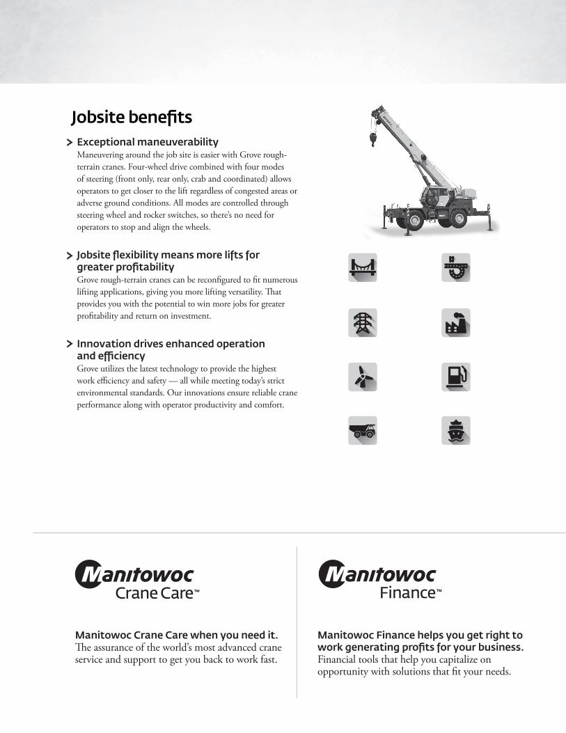
Exceptional maneuverability Maneuvering around the job site is easier with Grove rough-terrain cranes. Four-wheel drive combined with four modes of steering (front only, rear only, crab and coordinated) allows operators to get closer to the lift regardless of congested areas or adverse ground conditions. All modes are controlled through steering wheel and rocker switches, so there’s no need for operators to stop and align the wheels.
Jobsite flexibility means more lifts for greater profitability Grove rough-terrain cranes can be reconfigured to fit numerous lifting applications, giving you more lifting versatility. That provides you with the potential to win more jobs for greater profitability and return on investment.
Innovation drives enhanced operation and efficiency Grove utilizes the latest technology to provide the highest work efficiency and safety — all while meeting today’s strict environmental standards. Our innovations ensure reliable crane performance along with operator productivity and comfort.
Manitowoc Crane Care when you need it. The assurance of the world’s most advanced crane service and support to get you back to work fast.
Manitowoc Finance helps you get right to work generating profits for your business. Financial tools that help you capitalize on opportunity with solutions that fit your needs.
Jobsite benefits
4
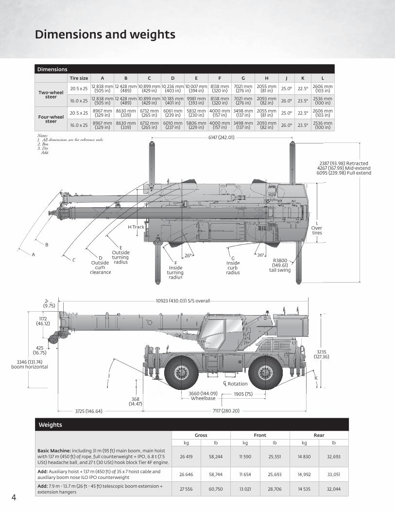
Dimensions
Tire size A B C D E F G H J K L
Two-wheel steer
20.5 x 25 12 838 mm(505 in)
12 428 mm(489)
10 899 mm(429 in)
10 236 mm(403 in)
10 007 mm(394 in)
8138 mm(320 in)
7021 mm(276 in)
2055 mm(81 in) 25.0° 22.5° 2606 mm
(103 in)
16.0 x 25 12 838 mm(505 in)
12 428 mm(489)
10 899 mm(429 in)
10 185 mm(401 in)
9981 mm(393 in)
8138 mm(320 in)
7021 mm(276 in)
2093 mm(82 in) 26.0° 23.5° 2536 mm
(100 in)
Four-wheel steer
20.5 x 25 8967 mm(329 in)
8630 mm(339)
6732 mm(265 in)
6061 mm(239 in)
5832 mm(230 in)
4000 mm(157 in)
3498 mm(137 in)
2055 mm(81 in) 25.0° 22.5° 2606 mm
(103 in)
16.0 x 25 8967 mm(329 in)
8630 mm(339)
6732 mm(265 in)
6010 mm(237 in)
5806 mm(229 in)
4000 mm(157 in)
3498 mm(137 in)
2093 mm(82 in) 26.0° 23.5° 2536 mm
(100 in)
Notes:1. All dimensions are for reference only2. Boom elevation is -3° to +76°3. Dimensions shown are based on 20.5 x 25 tires. Add 34,5 mm for 16.0 x 25 tires.
Dimensions and weights
Weights
Gross Front Rear
kg lb kg lb kg lb
Basic Machine: including 31 m (95 ft) main boom, main hoist with 137 m (450 ft) of rope, full counterweight + IPO, 6.8 t (7.5 USt) headache ball, and 27 t (30 USt) hook block Tier 4F engine.
26 419 58,244 11 590 25,551 14 830 32,693
Add: Auxiliary hoist + 137 m (450 ft) of 35 x 7 hoist cable and auxiliary boom nose ILO IPO counterweight
26 646 58,744 11 654 25,693 14,992 33,051
Add: 7.9 m - 13.7 m (26 ft - 45 ft) telescopic boom extension + extension hangers
27 556 60,750 13 021 28,706 14 535 32,044
6147 (242.01)
2387 (93.98) Retracted4267 (167.99) Mid-extend6095 (239.98) Full extend
LOver tires
26°R3800(149.61)
tail swing
A
B
C DOutside
curb clearance
EOutsideturning radius F
Insideturning radius
GInsidecurb
radius
H Track
26°
248 (9.75)
3346 (131.74)boom horizontal
425(16.75)
1172(46.12)
J
368(14.47)
3725 (146.64)Boom overhang
10923 (430.03) S/S overall
3235(127.36)
KCL Rotation
1905 (75)
7117 (280.20)Chassis length
3660 (144.09)Wheelbase
23426609
LOver tires
26°R3800(149.61)
tail swing
C DOutside
curbclearance
EOutsideturningradius
gF
Insideturning radius
g
GInsidecurb
radius
H Track
26°
48 .75)
2)
J
10923 (430.03) S/S overall1
323(127.3
KCLCC Rotation
1905 (75)3660 (144 09)
5Grove RT530E-2
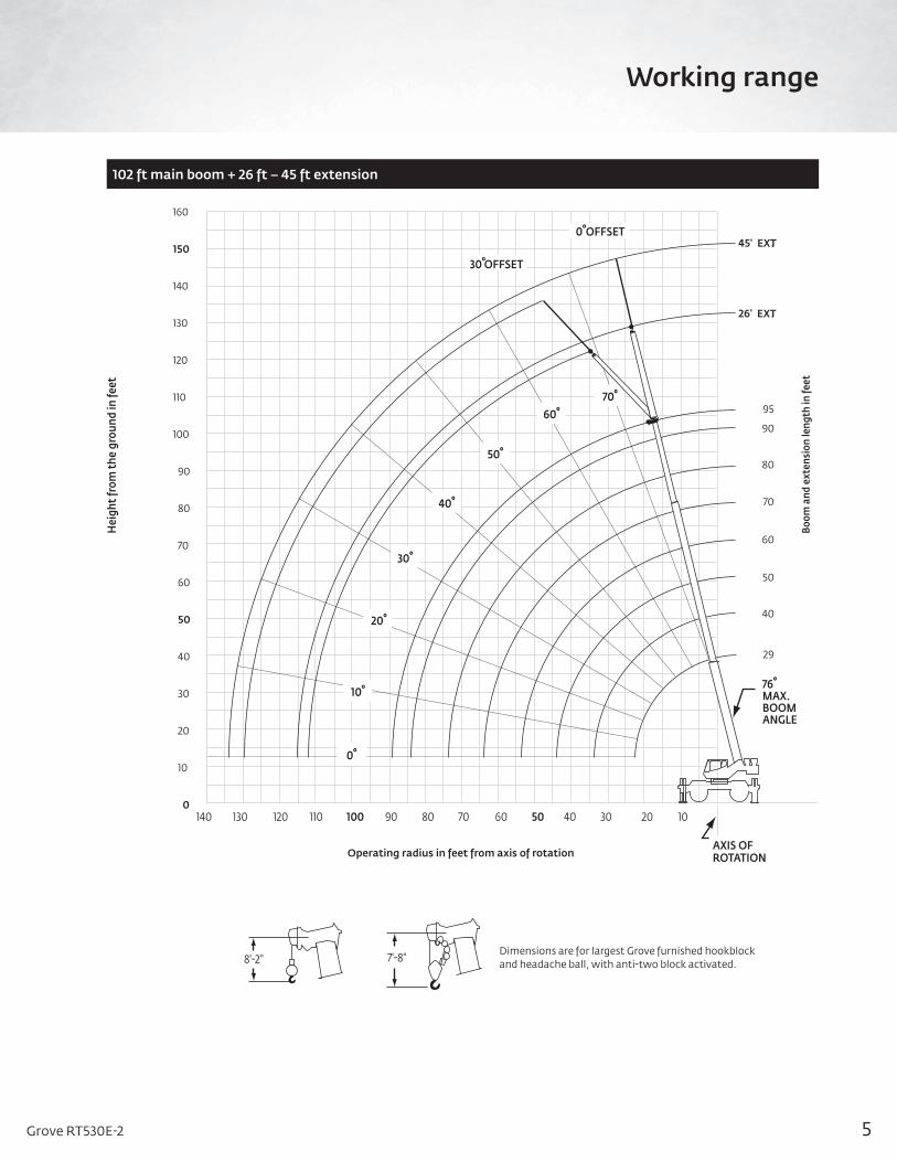
Working range
102 ft main boom + 26 ft – 45 ft extension
45' EXT.
26' EXT.
95
90
80
70
60
50
40
29
160
150
140
130
120
110
100
90
80
70
60
50
40
30
20
10
0
76°MAX.BOOMANGLE
140 120 100 80 60 40 20130 110 90 70 50 30 10
0° OFFSET
30° OFFSET
10°
0°
20°
30°
40°
50°
60° 70°
8'-2" 7'-8" Dimensions are for largest Grove furnished hookblock and headache ball, with anti-two block activated.
Hei
ght f
rom
the
grou
nd in
feet
Boom
and
ext
ensi
on le
ngth
in fe
et
Operating radius in feet from axis of rotationAXIS OFROTATION

6
Working Range Subhead
Load chart
FeetMain boom length in feet
29 40 50 60 70 80 90 95
10 60,000(60.5)
50,100(69.5)
46,950(74.5) — — — — —
12 54,650 (56)
50,100(66.5)
44,950(72)
38,850*(76) — — — —
15 42,850(47.5)
43,800(61.5)
41,050(68)
36,000(72)
29,450*(76)
22,450*(76) — —
20 30,700(30)
31,650(53)
32,100(61.5)
29,500(67)
27,400(71)
22,450(73.5)
18,550*(76)
15,500*(76)
25 — 24,050(42.5)
24,500(54.5)
24,800(61.5)
23,100(66.5)
19,250(70)
16,500(72.5)
15,300(74)
30 — 18,800(29)
19,250(47)
19,550(56)
19,600(61.5)
16,850(66)
14,400(69)
13,200(70.5)
35 — — 15,550(38)
15,850(49.5)
16,000(56.5)
14,850(61.5)
12,700(65.5)
11,500(67.5)
40 — — 12,800(26)
12,950(42.5)
13,000(51.5)
13,050(57.5)
11,000(62)
10,000(64)
45 — — — 10,450(34.5)
10,500(46.5)
10,550(53)
9630(58.5)
9060(60.5)
50 — — — 8610(23.5)
8630(39.5)
8670(48)
8720(54.5)
7990(57)
55 — — — — 7170(32)
7200(43)
7250(50)
7100(53)
60 — — — — 6000(22)
6030(37)
6100(45.5)
6110(49)
65 — — — — — 5080(30)
5120(40.5)
5150(44.5)
70 — — — — — 4270(20.5)
4330(35)
4350(40)
75 — — — — — — 3650(28.5)
3700(34.5)
80 — — — — — — 3100(20)
3100(28)
85 — — — — — — — 2600(20)
Minimum boom angle (°) for indicated length (no load) 0Maximum boom length (ft.) at 0° boom angle (no load) 95
*This capacity is based on maximum boom angleNOTE: ( ) Boom angles are in degrees.
A6-829-101755
Boom angleLifting capacities at 0° boom angle
29 ft 40 ft 50 ft 60 ft 70 ft 80 ft 90 ft 95.2 ft
0°26,100(22.8)
15,800(13.8)
11,000(43.8)
7430(53.8)
5220(63.8)
3730(73.8)
2660(83.8)
2220(89)
NOTE: ( ) Reference radii in feet.Figures above the bold line indicate optimal lift capacity within boom length sections.
29 ft – 95 ft 8416 lb 100%20 ft spread
360°
Pounds
THIS CHART IS ONLY A GUIDE AND SHOULD NOT BE USED TO OPERATE THE CRANE. The individual crane’s load chart, operating instructions and other instructional plates must be read and understood prior to operating the crane.
7Grove RT530E-2
Load Chart Subhead
Load chart
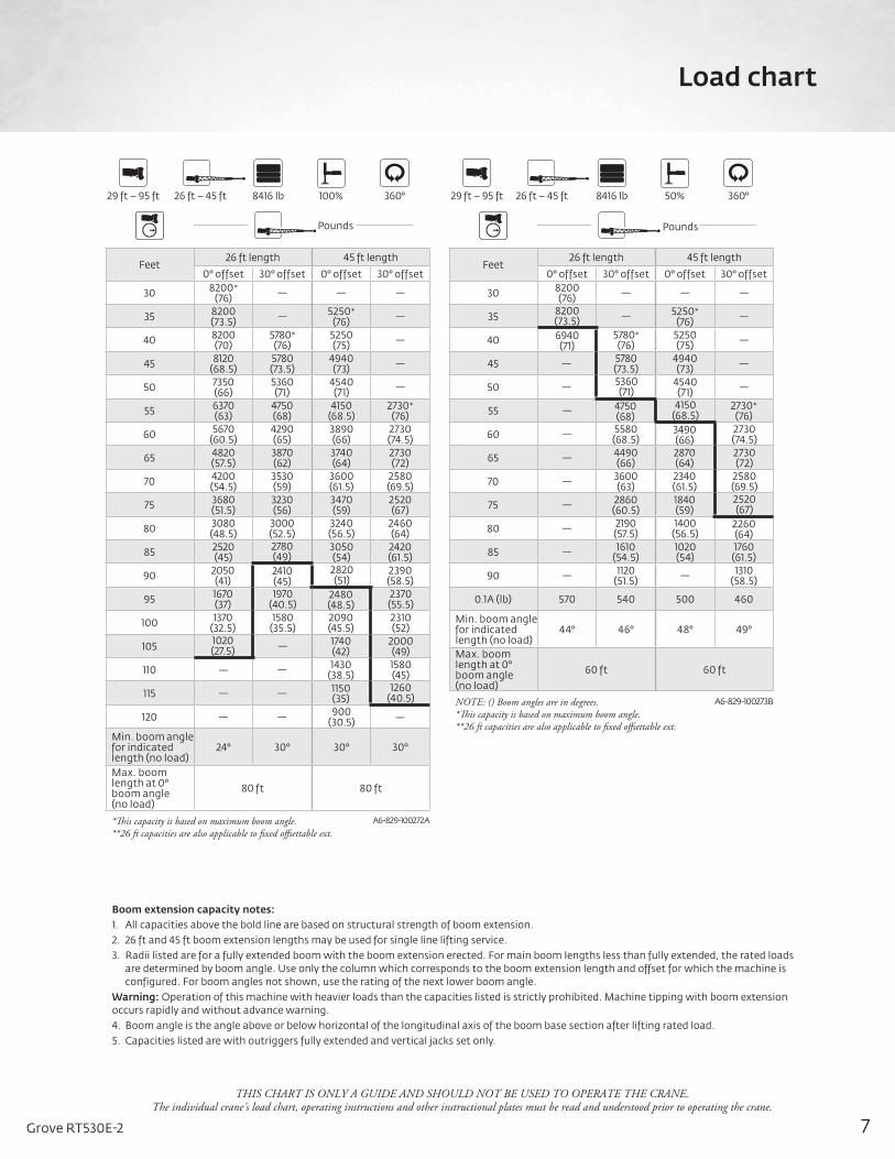
Feet26 ft length 45 ft length
0° offset 30° offset 0° offset 30° offset
30 8200*(76) — — —
35 8200(73.5) — 5250*
(76) —
40 8200(70)
5780*(76)
5250(75) —
45 8120(68.5)
5780(73.5)
4940(73) —
50 7350(66)
5360(71)
4540(71) —
55 6370(63)
4750(68)
4150(68.5)
2730*(76)
60 5670(60.5)
4290(65)
3890(66)
2730(74.5)
65 4820(57.5)
3870(62)
3740(64)
2730(72)
70 4200(54.5)
3530(59)
3600(61.5)
2580(69.5)
75 3680(51.5)
3230(56)
3470(59)
2520(67)
80 3080(48.5)
3000(52.5)
3240(56.5)
2460(64)
85 2520(45)
2780(49)
3050(54)
2420(61.5)
90 2050(41)
2410(45)
2820(51)
2390(58.5)
95 1670(37)
1970(40.5)
2480(48.5)
2370(55.5)
100 1370(32.5)
1580(35.5)
2090(45.5)
2310(52)
105 1020(27.5) — 1740
(42)2000(49)
110 — — 1430(38.5)
1580(45)
115 — — 1150(35)
1260(40.5)
120 — — 900(30.5) —
Min. boom angle for indicated length (no load)
24° 30° 30° 30°
Max. boom length at 0° boom angle (no load)
80 ft 80 ft
*This capacity is based on maximum boom angle.**26 ft capacities are also applicable to fixed offsettable ext.
A6-829-100272A
Feet26 ft length 45 ft length
0° offset 30° offset 0° offset 30° offset
30 8200(76) — — —
35 8200(73.5) — 5250*
(76) —
40 6940(71)
5780*(76)
5250(75) —
45 — 5780(73.5)
4940(73) —
50 — 5360(71)
4540(71) —
55 — 4750(68)
4150(68.5)
2730*(76)
60 — 5580(68.5)
3490(66)
2730(74.5)
65 — 4490(66)
2870(64)
2730(72)
70 — 3600(63)
2340(61.5)
2580(69.5)
75 — 2860(60.5)
1840(59)
2520(67)
80 — 2190(57.5)
1400(56.5)
2260(64)
85 — 1610(54.5)
1020(54)
1760(61.5)
90 — 1120(51.5) — 1310
(58.5)
0.1A (lb) 570 540 500 460
Min. boom angle for indicated length (no load)
44° 46° 48° 49°
Max. boom length at 0° boom angle (no load)
60 ft 60 ft
NOTE: () Boom angles are in degrees.*This capacity is based on maximum boom angle.**26 ft capacities are also applicable to fixed offsettable ext.
A6-829-100273B
Boom extension capacity notes:1. All capacities above the bold line are based on structural strength of boom extension.2. 26 ft and 45 ft boom extension lengths may be used for single line lifting service.3. Radii listed are for a fully extended boom with the boom extension erected. For main boom lengths less than fully extended, the rated loads
are determined by boom angle. Use only the column which corresponds to the boom extension length and offset for which the machine is configured. For boom angles not shown, use the rating of the next lower boom angle.
Warning: Operation of this machine with heavier loads than the capacities listed is strictly prohibited. Machine tipping with boom extension occurs rapidly and without advance warning.4. Boom angle is the angle above or below horizontal of the longitudinal axis of the boom base section after lifting rated load.5. Capacities listed are with outriggers fully extended and vertical jacks set only.
29 ft – 95 ft 29 ft – 95 ft8416 lb 8416 lb100% 50%360° 360°26 ft – 45 ft 26 ft – 45 ft
Pounds Pounds
THIS CHART IS ONLY A GUIDE AND SHOULD NOT BE USED TO OPERATE THE CRANE. The individual crane’s load chart, operating instructions and other instructional plates must be read and understood prior to operating the crane.

8
Load Chart Subhead
Load chart
FeetMain boom length in feet
29 40 50 60 70 80 90 95
10 60,000(60.5)
48,000(69.5)
45,000(74.5) — — — — —
12 53,300(56)
48,000(66.5)
44,950(72)
37,000*(76) — — — —
15 42,100(47.5)
40,500(61.5)
38,350(68)
36,000(72)
27,400*(76)
21,000*(76) — —
20 23,950(30)
23,850(53)
23,900(61.5)
24,050(67)
23,200(71)
21,000(73.5)
17,000*(76)
15,500*(76)
25 — 15,850(42.5)
15,950(54.5)
16,150(61.5)
16,350(66.5)
16,400(70)
15,950(72.5)
15,500(74)
30 — 11,350(29)
11,500(47)
11,650(56)
11,800(61.5)
12,000(66)
12,150(69)
12,100(70.5)
35 — — 8620(38)
8820(49.5)
8930(56.5)
9050(61.5)
9190(65.5)
9260(67.5)
40 — — 6610(26)
6820(42.5)
6900(51.5)
6990(57.5)
7100(62)
7150(64)
45 — — — 5350(34.5)
5400(46)
5470(53)
5550(58.5)
5600(60.5)
50 — — — 4220(23.5)
4260(39.5)
4310(48)
4370(54.5)
4410(57)
55 — — — — 3350(32)
3390(43)
3430(50)
3460(53)
60 — — — — 2600(22)
2640(37)
2670(45.5)
2700(49)
65 — — — — — — 2050(40.5)
2060(44.5)
70 — — — — — — 1520(35)
1530(40)
75 — — — — — — 1070(28.5)
1080(34.5)
0.1A (lb) 660 610 580 560 550 540 540 530
Min. boom angle for indicated length (no load) 15° 20°
Max. boom length at 0° boom angle (no load) 80
NOTE: Boom angles are in degrees.*This capacity is based on maximum obtainable boom angle.
A6-829-100270A
FeetMain boom length in feet
29 40 50 60 70 80 90 95
10 34,700(60.5)
32,400(69.5)
30,400(74.5) — — — — —
12 26,200(56)
25,400(66.5)
24,100(72)
22,900*(76) — — — —
15 17,750(47.5)
17,550(61.5)
17,550(68)
17,250(72)
16,550*(76)
10,900*(76) — —
20 10,650(30)
10,600(53)
10,650(61.5)
10,750(67)
11,000(71)
10,900(73.5)
10,500(76)
10,350(76)
25 — 6930(42.5)
7020(54.5)
7170(61.5)
7350(66.5)
7560(70)
7610(72.5)
7490(74)
30 — 4670(29)
4780(47)
4950(56)
5080(61.5)
5240 (66)
5390(69)
5480(70.5)
35 — — 3270(38)
3450(49.5)
3550(56.5)
3660(61.5)
3780(65.5)
3850(67.5)
40 — — 2170(26)
2370(42.5)
2440(51.5)
2520(57.5)
2620(62)
2670(64)
45 — — — 1550(34.5)
1600(46)
1660(53)
1740(58.5)
1780(60.5)
50 — — — — — — 1050(54.5)
1080(57)
0.1A (lb) 660 610 580 560 550 540 540 530
Min. boom angle for indicated length (no load) 33° 43° 51° 53° 55°
Max. boom length at 0° boom angle (no load) 50
NOTE: Boom angles are in degrees.*This capacity is based on maximum obtainable boom angle.
A6-829-100271A
29 ft – 95 ft 29 ft – 95 ft8416 lb 8416 lb360° 360°
Boom angle
Lifting capacities at 0° boom angle on outriggers at 50% extended 360°
29 40 50 60 70 80
0° 18,800(22.8)
9000(33.8)
5400(43.8)
3480(53.8)
2100(63.8)
1130(73.8)
NOTE: ( ) Reference radii in feet.
Boom angle
Lifting capacities at 0° boom angle on outriggers at 50% extended 360°
29 40 50
0° 8310(22.8)
3390(33.8)
1480(43.8)
NOTE: ( ) Reference radii in feet.
50%14 ft spread
0%7 ft 10 in spread
Pounds Pounds
THIS CHART IS ONLY A GUIDE AND SHOULD NOT BE USED TO OPERATE THE CRANE. The individual crane’s load chart, operating instructions and other instructional plates must be read and understood prior to operating the crane.
9Grove RT530E-2
Working RangeSubhead
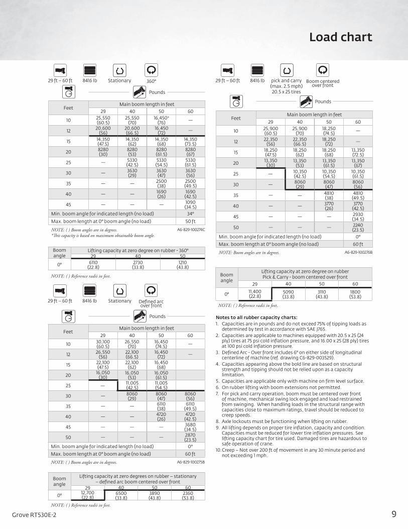
Load chart
FeetMain boom length in feet
29 40 50 60
10 25,550(60.5)
25,550(70)
16,450*(76) —
12 20,600(56)
20,600(66.5)
16,450(72) —
15 14,350(47.5)
14,350(62)
14,350(68)
14,350(73.5)
20 8280(30)
8280(53)
8280(61.5)
8280(67)
25 — 5330(42.5)
5330(54.5)
5330(61.5)
30 — 3630(29)
3630(47)
3630(56)
35 — — 2500(38)
2500(49.5)
40 — — 1690(26)
1690(42.5)
45 — — — 1090(34.5)
Min. boom angle for indicated length (no load) 34°
Max. boom length at 0° boom angle (no load) 50 ft
NOTE: ( ) Boom angles are in degrees.*This capacity is based on maximum obtainable boom angle.
A6-829-100274C
FeetMain boom length in feet
29 40 50 60
10 30,100(60.5)
26,550(70)
16,450(74.5) —
12 26,550(56)
22,100(66.5)
16,450(72) —
15 22,100(47.5)
22,100(62)
16,450(68)
20 16,050(30)
16,050(53)
16,050(61.5)
25 — 11,005(42.5)
11,005(54.5)
30 — 8060(29)
8060(47)
8060(56)
35 — — 6110(38)
6110(49.5)
40 — — 4720(26)
4720(42.5)
45 — — — 3680(34.5)
50 — — — 2870(23.5)
Min. boom angle for indicated length (no load) 0°
Max. boom length at 0° boom angle (no load) 60 ft
NOTE: ( ) Boom angles are in degrees. A6-829-100275B
FeetMain boom length in feet
29 40 50 60
10 25,900(60.5)
25,900(70)
18,250(74.5) —
12 22,350(56)
22,350(66.5)
18,250(72) —
15 18,250(47.5)
18,250(62)
18,250(68)
13,350(72.5)
20 13,350(30)
13,350(53)
13,350(61.5)
13,350(67)
25 — 10,350(42.5)
10,350(54.5)
10,350(61.5)
30 — 8060(29)
8060(47)
8060(56)
35 — — 4810(38)
4810(49.5)
40 — — 3770(26)
3770(42.5)
45 — — — 2930(34.5)
50 — — — 2240(23.5)
Min. boom angle for indicated length (no load) 0°
Max. boom length at 0° boom angle (no load) 60 ft
NOTE: Boom angles are in degrees. A6-829-100276B
29 ft – 60 ft
29 ft – 60 ft
29 ft – 60 ft8416 lb
8416 lb
8416 lb360°
Defined arc over front
Boom centeredover front
Stationary
Stationary
pick and carry(max. 2.5 mph)20.5 x 25 tires
Boom angle
Lifting capacity at zero degree on rubber - 360°29 40 50
0° 6110(22.8)
2730(33.8)
1210(43.8)
NOTE: ( ) Reference radii in feet.
Boom angle
Lifting capacity at zero degrees on rubber – stationary – defined arc boom centered over front
29 40 50 60
0° 12,700(22.8)
6500(33.8)
3890(43.8)
2360(53.8)
NOTE: ( ) Reference radii in feet.
Boom angle
Lifting capacity at zero degree on rubberPick & Carry - boom centered over front
29 40 50 60
0° 11,400(22.8)
5090(33.8)
3110(43.8)
1800(53.8)
NOTE: ( ) Reference radii in feet.
Notes to all rubber capacity charts:1. Capacities are in pounds and do not exceed 75% of tipping loads as
determined by test in accordance with SAE J765.2. Capacities are applicable to machines equipped with 20.5 x 25 (24
ply) tires at 75 psi cold inflation pressure, and 16.00 x 25 (28 ply) tires at 100 psi cold inflation pressure.
3. Defined Arc - Over front includes 6° on either side of longitudinal centerline of machine (ref. drawing C6-829-003529).
4. Capacities appearing above the bold line are based on structural strength and tipping should not be relied upon as a capacity limitation.
5. Capacities are applicable only with machine on firm level surface.6. On rubber lifting with boom extensions not permitted.7. For pick and carry operation, boom must be centered over front
of machine, mechanical swing lock engaged and load restrained from swinging. When handling loads in the structural range with capacities close to maximum ratings, travel should be reduced to creep speeds.
8. Axle lockouts must be functioning when lifting on rubber.9. All lifting depends on proper tire inflation, capacity and condition.
Capacities must be reduced for lower tire inflation pressures. See lifting capacity chart for tire used. Damaged tires are hazardous to safe operation of crane.
10. Creep – Not over 200 ft of movement in any 30 minute period and not exceeding 1 mph.
Pounds
Pounds
Pounds

10
Load Chart Subhead
Weight reductions for load handling devices
26 ft offsettable boom extension lb
Erected* 2960
26 ft – 45 ft telescopic boom extension lb
Erected (retracted)* 4220
Erected (extended)* 5780
Reduction of main boom capacities*
Auxiliary boom nose lb
142
Hook blocks and headache balls lb
30 USt, 3-sheave 580 +
15 USt, 2-sheave 425 +
7.5 USt overhaul ball 354 +
7.5 USt headache ball 338 +
+ Refer to rating plate for actual weight
When lifting over swingaway and/or jib combinations, deduct total weight of all load handling devices reeved over main boom nose directly from swingaway or jib capacity.
NOTE: All load handling devices and boom attachments are considered part of the load and suitable allowances MUST BE MADE for their combined weights. Weights are for Grove furnished equipment.
Line pulls and reeving information
Hoists Cable specs Permissible line pulls
Nominal cable length
Main16 mm (5/8 in)
6 x3 7 class EIPS, IWRC Special Flexible Min. Breaking Str. 41,200 lb
11,640 lb* 450 ft
Main and auxiliary
16 mm (5/8 in) 35 x 7 Class, EEIPS+Rotation Resistant
(non-rotating)Min. Breaking Str. 61,200 lb
11,640 lb* 450 ft
Main and auxiliary
18 mm (11/16 in) K™-100 Synthetic hoist rope (ISO) Min. breaking
strength 63,700 lb12,740 lb* 463 ft
Hoist performance
Wire rope layer Hoist line pulls two-speed hoist Drum rope capacity (ft)
Lowavailable lb* Layer Total
1 11,640 77 77
2 10,480 85 162
3 9530 94 256
4 8730 102 358
5 8060 111 469
6 7490 119 588
* Max lifting capacity: 6 x 37 class = 11,640 lb 35 x 7 class = 11,640 lb
Working area diagram
Bold lines determine the limiting position of any load for operation within working areas indicated.
Load handling
For specific configurations refer to www.cranelibrary.com.
++
Over side
Over rear
Over side
Over front
Centerline of rotation
See note at bottom
Longitudinal centerline
of crane
Centerline of outrigger support
Centerline of boom
CG of load
Diagram of working area
360°
Lifting on outriggers
Rear axle oscillation
lockouts must be set to
maintain 360° capacities
Boom centered over front
Front
12°
360°
Lifting on tires
C6-829-003529C6-829-001159
6°
THIS CHART IS ONLY A GUIDE AND SHOULD NOT BE USED TO OPERATE THE CRANE. The individual crane’s load chart, operating instructions and other instructional plates must be read and understood prior to operating the crane.
Capacity reductions for synthetic rope use:Main boom
chartsExtension
charts
Outriggers fully extended 100 lb 0 lb
Outriggers 50% extended 480 lb 120 lb
Outriggers 0% extended 470 lb N/A
On Rubber 210 lb N/A
If synthetic rope is installed on either the main or aux hoist, and wire rope is installed on the other hoist, no capacity reductions are required.
The approximate weight of 5/8 in wire rope is 1.0 lb/ft. The approximate weight of 18 mm synthetic rope is 0.16 lb/ft. *With certain boom and hoist tackle combinations, the allowable line pull may be limited by hoist performance. Refer to Hoist Performance table for lift planning to ensure adequate hoist performance on drum rope layer required.

11Grove RT530E-2
Load Chart Subhead
Specifications
Hydraulic systemTwo main pumps ([1] piston and [1] gear) with a combined capacity of 316,5 L/min (83.6 gpm). Maximum operating pressure: 275,7 bar (4000 psi). Three section pressure compensated valve bank. Return line type filter with full flow by-pass protection and service indicator. Replaceable cartridge with micron filtration rating of 5/12/16. 396 L (104.6 gal) hydraulic reservoir. System pressure test ports.
Hoist specifications (HP15C-17G) main and
auxiliary hoistPlanetary reduction with automatic spring applied multi-disk wet brake. Electronic hoist drum rotation indicators, and hoist drum cable followers. Hoist maximum single line pull: 1st layer: 5280 kg (11,640 lb) 3rd layer: 4323 kg (9530 lb) 5th layer: 3656 kg (8060 lb) Maximum permissible line pull: 5280 kg (11,640 lb) with 35 x 7 class rope Maximum single line speed: 136 m/min (445 fpm) Rope construction: 35 x 7 Rotation Resistant Rope diameter: 16 mm (5/8 in) Rope length: Main hoist: 137 m (450 ft) Auxiliary hoist: 137 m (450 ft) Maximum rope stowage: 181 m (596 ft)
Carrier
ChassisBox section frame fabricated from high-strength, low alloy steel. Front/rear towing, lifting, and tie down lugs.
Outrigger systemFour hydraulic telescoping single-stage double box beam outriggers with inverted jacks and integral holding valves. Three position setting, 0%, 50% and fully extended. All steel fabricated quick release type outrigger floats, 362 mm (14.25 in) square. Maximum outrigger pad load: 24 857 kg (54,800 lb) Outrigger monitoring system with outrigger beam position display on R.C.L. screen (required in North America, Canada, and European Union countries).
Outrigger controlsControls and crane level indicator located in cab. Extension and retraction are through the CCS system.
Superstructure
Boom8,8 m – 29,0 m (29 ft – 95 ft) four-section, synchronized full-power boom. Maximum tip height: 31,2 m (102.5 ft).
Optional telescopic swingaway extension*7,9 m – 13,7 m (26 ft – 45 ft) offsettable telescopic lattice swingaway extension. Offsets at 0° and 30°. Stows alongside base boom section. Maximum tip height: 44,5 m (146 ft).
Boom noseThree nylatron sheaves mounted on heavy duty tapered roller bearings with removable pin-type rope guards. Quick reeve type boom nose.
Boom elevation One double-acting hydraulic cylinder with integral holding valve provides elevation from -3° to +76°.
Crane Control System (CCS)“Graphic Display” load moment and anti-two block system with audio-visual warning and control lever lockout. This system provides electronic display of boom angle, length, radius, tip height, relative load moment, maximum permissible load, load indication and warning of impending two-block condition. The Work Area Definition System allows the operator to pre-select and define safe working areas. If the crane approaches the pre-set limits, audio-visual warnings aid the operator in avoiding jobsite obstructions.
CabFull-vision, all-steel fabricated with acoustical lining and tinted safety glass throughout. Adjustable deluxe seat incorporates armrest-mounted electronic single or dual axis controllers and a jog dial for easier data input. Tilt/telescoping steering wheel with various controls incorporated into the steering column. Other standard features include hot water heater, cab circulating air fan, sliding side and rear windows, sliding skylight with electric wiper and sunscreen, electric windshield wash/wipe, fire extinguisher, seat belt, air conditioning and dual cab mounted work light.
SwingSingle speed, planetary swing drive with foot applied multi-disc wet brake. Spring applied, hydraulically released swing brake. Single position mechanical house lock, operated from cab. Maximum speed: 2 rpm.
Counterweight3817 kg (8416 lb) pinned to superstructure.

12
Load Chart Subhead
*Denotes optional equipment
Specifications
Carrier (cont’d)
Engine (Tier 4F)Cummins QSB 6.7L diesel six cylinder, turbo-charged with Cummins Compact Catalyst (CCC) & selective catalytic reduction (SCR) combo muffler, using diesel exhaust fluid (DEF) injection. Meets emission per U.S. Tier 4F and E.U. Stage IV. 122 kW (164 bhp) at 2300 rpm. Maximum torque: 732 Nm (540 ft lb) at 1500 rpm. Fuel requirement: Maximum of 15 ppm sulfur content (ultra-low sulfur diesel fuel) and diesel exhaust fluid (DEF). Note: Tier 4F engine required in North American, Canada and European Union countries.
Engine (Tier 3)Cummins QSB 6.7 L diesel, six cylinders, 119 kW (160 bhp) (gross) at 2500 rpm. Maximum torque: 731 Nm (539 ft-lb) at 1500 rpm.
Fuel tank capacity220 L (58 gal)
TransmissionRange-shift six-speed (three speeds x two range, both forward and reverse)
Electrical systemTwo (2) 12 V maintenance free batteries. 24 V starting and lighting. Battery disconnect. Full CANBUS diagnostic system.
Drive4 x 4
SteeringFully independent power steering. Front: Full hydraulic steering wheel controlled. Rear: Full hydraulic switch controlled. Provides infinite variations with four main steering modes: front only, rear only, crab and coordinated. Rear steer indicator. Outside turning radius: 5,8 m (19.1 ft) Inside turning radius: 4 m (13.1 ft)
AxlesFront: Drive/steer with differential and planetary reduction hubs rigid mounted to frame. Rear: Drive/steer with differential and planetary reduction hubs pivot mounted to frame.
Oscillation lockoutsAutomatic full hydraulic lockouts on rear axle permits 18,8 cm (7 in) oscillation with boom centered over the front only.
BrakesFull hydraulic split circuit disc-type brakes operating on all wheels. Spring-applied, hydraulically released parking brake mounted on front axle.
TiresStandard: 20.5 x 25 - 24 bias ply *Option: 16.0 x 25 - 28 bias ply
LightsFull lighting including turn indicators, head, tail, brake and hazard warning lights.
Maximum speed40 km/h (25 mph) at 2500 rpm
Gradeability (theoretical)119% (at engine stall)(Based on 27 556 kg [60,750 lb] GVW) 20.5 x 25 tires, 29 m (95 ft) main boom, plus 13,7 m (45 ft) telescopic swingaway, 3817 kg (8416 lb) counterweight, 27 t (30 USt) hook block and 6,8 t (7.5 USt) headache ball.
Miscellaneous standard equipment Full width steel fenders, full length steel decking with anti-skid, dual rear view mirrors, hook block tied-down, electronic back-up alarm, light package, front stowage well, tachometer/hourmeter, rear wheel position indicator, hot water cab heater, air conditioning, hoist mirrors, engine distress A/V warning system, front/rear tie-down and tow lugs, coolant sight level indicator, CraneSTAR asset management system.
*Optional equipment
• Value package: Includes 7,92 m – 13,7 m (26 ft – 45 ft) telescoping swingaway and 360° positive swing lock
• Auxiliary Hoist Package: Includes model HP15C-17G auxiliary hoist with electronic hoist drum rotation indicator, hoist drum cable follower, 137 m (450 ft) of 16 mm (5/8 in) 35 x 7 class wire rope and auxiliary sheave boom nose.
• 360⁰ positive mechanical swing lock• Rear pintle hook• Cab-controlled cross axle differential locks (front and rear)• PAT event recorder download kit• Single axis electric controllers• Third wrap indicator with hoist cut-out for main hoist or main and auxiliary hoist
• Vertical LMI light Tower (externally mounted) • Synthetic rope for main and/or auxiliary hoist• Emergency stop buttons on each side of carrier• Second beacon light• -29ºC / -20ºF cold weather package• -40ºC / -40ºF arctic weather package
13Grove RT530E-2
Load Chart Subhead
Symbol glossary
Drive
RotationElectrical system
Suspension
Fuel tank capacity
Tires
Engine
Brakes
Outrigger controls
Axles Outriggers
Transmission
Frame
Steering
Lights
Boom elevation
Cab
Swing
Crane control system
Hydraulic system
Insert
Hoist
Boom nose
Radius
Boom extension
Boom length
Grade
Gear
Boom
Counterweight
Speed
Oil
Extension
Hook blockH
Heavy duty jib
Height (no max)

14
Notes

15Grove RT530E-2
Working RangeSubhead
Notes
Manitowoc Cranes
ChinaShanghai, China Tel: +86 21 6457 0066Fax: +86 21 6457 4955
Greater Asia-Pacific Singapore Tel: +65 6264 1188 Fax: +65 6862 4040
Europe, Middle East, Africa Dardilly, France - TOWERSTel: +33 (0)4 72 18 20 20 Fax: +33 (0)4 72 18 20 00
Wilhelmshaven, Germany - MOBILETel: +49 (0) 4421 294 454 Fax: +49 (0) 4421 2944301
Americas Manitowoc, Wisconsin, USA Tel: +1 920 684 6621 Fax: +1 920 683 6277
Shady Grove, Pennsylvania, USA Tel: +1 717 597 8121 Fax: +1 717 597 4062
Regional headquarters
www.manitowoccranes.com
This document is non-contractual. Constant improvement and engineering prog-ress make it necessary that we reserve the right to make specification, equipment, and price changes without notice. Illustrations shown may include optional equipment and accessories and may not include all standard equipment.
©2016 All Rights Reserved – Manitowoc Cranes, LLC and its affiliates.Form No. RT530E-2 PGPart No. 07-002/2M/0616
Manitowoc Crane Care when you need it. The assurance of the world’s most advanced crane service and support to get you back to work fast.
Manitowoc Finance helps you get right to work generating profits for your business. Financial tools that help you capitalize on opportunity with solutions that fit your needs.