rugged portable data terminal phl 8000 series
TRANSCRIPT
Rugged Portable Data Terminal
PHL 8000 series
The PHL 8100 and PHL 8200 Portable Data Terminals are rugged devices compatible with Microsoft Windows® CE .Net technology. User Manual
Opticon PHL 8000 series
User Manual
2
All information subject to change without notice.
Document History Model Number: PHL 8100 / PHL 8200
Edition: 1
Date: 2008/2009
Copyright 2008 Opticon. All rights reserved. This manual may not, in whole or in part, be copied, photocopied, reproduced, translated or converted to any electronic or machine readable form without prior written consent of Opticon.
Limited Warranty and Disclaimers PLEASE READ THIS MANUAL CAREFULLY BEFORE INSTALLING OR USING THE PRODUCT.
Serial Number A serial number appears on all Opticon products. This official registration number is directly related to the device purchased. Do not remove the serial number from your Opticon device. Removing the serial number voids the warranty.
Warranty Unless otherwise agreed in a written contract, all Opticon products are warranted against defects in materials and workmanship for two years after purchase. Opticon will repair or, at its option, replace products that are defective in materials or workmanship with proper use during the warranty period. Opticon is not liable for damages caused by modifications made by a customer. In such cases, standard repair charges will apply. If a product is returned under warranty and no defect is found, standard repair charges will apply. Opticon assumes no liability for any direct, indirect, consequential or incidental damages arising out of use or inability to use both the hardware and software, even if Opticon has been informed about the possibility of such damages.
Packaging The packing materials are recyclable. We recommend that you save all packing material to use should you need to transport your scanner or send it for service. Damage caused by improper packaging during shipment is not covered by the warranty.
Trademarks Trademarks used are the property of their respective owners.
Opticon Inc. and Opticon Sensors Europe B.V. are wholly owned subsidiaries of OPTOELECTRONICS Co., Ltd., 12-17, Tsukagoshi 4-chome, Warabi-shi, Saitama, Japan 335-0002. TEL +81-(0) 48-446-1183; FAX +81-(0) 48-446-1184
SUPPORT USA Europe Phone: 800-636-0090
Email: [email protected] Email: [email protected]
Web: www.opticonusa.com Web: www.opticon.com
Opticon PHL 8000 series
User Manual
3
Contents 1. Introduction................................................................................................................................. 9
1.1. About this Manual ............................................................................................................... 9 1.2. Safety ................................................................................................................................ 10 1.3. Battery Safety.................................................................................................................... 10 1.4. CE Statement.................................................................................................................... 11 1.5. Federal Communication Commission (FCC) Statement ................................................... 12
1.5.1. LED and Laser Safety Information............................................................................ 13 1.6. Recycling & Disposal ........................................................................................................ 13 1.7. Regulatory Information...................................................................................................... 13 1.8. Product Labeling ............................................................................................................... 14 1.9. System Specifications ....................................................................................................... 16 1.10. Environmental Specifications ............................................................................................ 17 1.11. Warranty and Service........................................................................................................ 17
2. Getting Started.......................................................................................................................... 18 2.1. Product Overview.............................................................................................................. 20
2.1.1. PHL 8100 .................................................................................................................. 20 2.1.2. PHL 8200 .................................................................................................................. 22
2.2. Charging the Battery Pack ................................................................................................ 24 2.2.1. Installing the Battery Pack ........................................................................................ 24 2.2.2. Charging the Battery Pack Using the Power Adapter ............................................... 26 2.2.3. Charging the Battery Pack with Single Dock ............................................................ 27
2.3. Handling the PDT.............................................................................................................. 28 2.3.1. Starting the PDT ....................................................................................................... 28 2.3.2. Power On/Power Off ................................................................................................. 28 2.3.3. Sound........................................................................................................................ 29 2.3.4. Using the Stylus ........................................................................................................ 30 2.3.5. Using the PHL 8100 Keypad..................................................................................... 30 2.3.6. Using the PHL 8200 Keypad..................................................................................... 32 2.3.7. Using the Earpiece Microphone................................................................................ 34
2.4. Navigating the Display ...................................................................................................... 35 2.4.1. Setting Time and Date .............................................................................................. 35
Opticon PHL 8000 series
User Manual
4
2.4.2. Entering Data ............................................................................................................ 36 2.4.3. The Command Bar.................................................................................................... 36 2.4.4. The Task Bar ............................................................................................................ 37 2.4.5. The Soft Keypad ....................................................................................................... 37 2.4.6. Setting Up Wireless LAN RF..................................................................................... 38 2.4.7. Reading Barcodes .................................................................................................... 45 2.4.8. Help........................................................................................................................... 46
2.5. Power Management .......................................................................................................... 47 2.5.1. Suspend Mode.......................................................................................................... 47 2.5.2. Resuming.................................................................................................................. 48
2.6. Resetting the PDT............................................................................................................. 48 2.6.1. Soft (Warm) Reset .................................................................................................... 48 2.6.2. Hard (Cold) Reset ..................................................................................................... 48
3. Settings ..................................................................................................................................... 49 3.1. Introduction ....................................................................................................................... 49 3.2. Control Panel .................................................................................................................... 49
3.2.1. Certificates ................................................................................................................ 54 3.2.2. Control Center........................................................................................................... 57 3.2.3. Date/Time ................................................................................................................. 61 3.2.4. Dialing Properties...................................................................................................... 61 3.2.5. Display Properties..................................................................................................... 64 3.2.6. Input Panel................................................................................................................ 66 3.2.7. Internet Options ........................................................................................................ 67 3.2.8. 3.2.11 Keyboard........................................................................................................ 69 3.2.9. Network and Dial-up Connections ............................................................................ 70 3.2.10. Owner ....................................................................................................................... 74 3.2.11. Password .................................................................................................................. 76 3.2.12. PC Connection.......................................................................................................... 77 3.2.13. Power........................................................................................................................ 78 3.2.14. Regional and Language Settings.............................................................................. 80 3.2.15. Remove Programs .................................................................................................... 82 3.2.16. Stylus Properties....................................................................................................... 83 3.2.17. System ...................................................................................................................... 85
Opticon PHL 8000 series
User Manual
5
3.2.18. Volume & Sounds Properties.................................................................................... 87 3.3. Task Bar and Start Menu .................................................................................................. 88
4. Communication ........................................................................................................................ 89 4.1. Installing & Setting Up Microsoft ActiveSync .................................................................... 89
4.1.1. Installing Microsoft ActiveSync on the Host PC ........................................................ 89 4.1.2. Connecting PDT to Host PC ..................................................................................... 89
4.2. Using ActiveSync .............................................................................................................. 89 4.2.1. Setting up a Partnership ........................................................................................... 89 4.2.2. ActiveSync File Synchronization............................................................................... 91
4.3. Networking ........................................................................................................................ 91 5. Software Applications.............................................................................................................. 92
5.1. Introduction ....................................................................................................................... 92 5.2. Software Applications........................................................................................................ 92
5.2.1. Inbox ......................................................................................................................... 92 5.2.2. Internet Explorer ..................................................................................................... 100 5.2.3. Microsoft WordPad ................................................................................................. 103 5.2.4. Remote Connection ................................................................................................ 107 5.2.5. Windows Explorer ................................................................................................... 108
5.3. DiskOnChip ..................................................................................................................... 110 5.3.1. Saving to Flash ....................................................................................................... 110 5.3.2. DiskOnChip Location .............................................................................................. 111 5.3.3. DiskOnChip Size..................................................................................................... 111
6. Appendix A – Enabling GPRS Module.................................................................................. 112 6.1. Inserting a SIM Card ....................................................................................................... 112 6.2. Setting up a GPRS connection ....................................................................................... 112
Table of Figures Figure 1-1: PHL 8100 product labels .......................................................................................... 14 Figure 1-2: PHL 8200 labels ....................................................................................................... 15 Figure 2-3: PHL 8100 package contents .................................................................................... 18 Figure 2-4: PHL 8200 package contents .................................................................................... 19 Figure 2-5: PHL 8100 overview .................................................................................................. 20 Figure 2-6: PHL 8200 overview .................................................................................................. 22 Figure 2-7: Release the hand strap ............................................................................................ 24 Figure 2-8: Detach the battery cover .......................................................................................... 25
Opticon PHL 8000 series
User Manual
6
Figure 2-9: Insert the battery pack.............................................................................................. 25 Figure 2-10: Replace the battery cover....................................................................................... 26 Figure 2-11: Charging using the power adapter ......................................................................... 26 Figure 2-12: Charging with Single Dock ..................................................................................... 27 Figure 2-13: Power-on splash screen......................................................................................... 28 Figure 2-14: Calibration .............................................................................................................. 29 Figure 2-15: PHL 8100 keypad................................................................................................... 30 Figure 2-16: PHL 8200 keypad................................................................................................... 32 Figure 2-17: Earpiece microphone ............................................................................................. 34 Figure 2-18: Date/Time properties.............................................................................................. 35 Figure 2-19: The Command bar and Task bar............................................................................ 37 Figure 2-20: Main tab.................................................................................................................. 39 Figure 2-21: Profile tab ............................................................................................................... 40 Figure 2-22: Status tab ............................................................................................................... 42 Figure 2-23: Diags tab ................................................................................................................ 43 Figure 2-24: Global tab ............................................................................................................... 44 Figure 2-25: Aiming the scanning beam ..................................................................................... 45 Figure 2-26: Good scanning position.......................................................................................... 45 Figure 2-27: Bad scanning position ............................................................................................ 46 Figure 2-28: Schemes tab .......................................................................................................... 47 Figure 3-29: Control Panel ......................................................................................................... 49 Figure 3-30: Enable Bluetooth Device........................................................................................ 51 Figure 3-31: Enable Bluetooth Successful ................................................................................. 51 Figure 3-32: Bluetooth Manager Scan Device............................................................................ 51 Figure 3-33: Bluetooth Manager scan inquiry............................................................................. 51 Figure 3-34: Bluetooth hardware error........................................................................................ 52 Figure 3-35: Bluetooth authentication error ................................................................................ 52 Figure 3-36: Bluetooth Enter PIN ............................................................................................... 52 Figure 3-37: Bluetooth Scan Device Trusted/Active ................................................................... 52 Figure 3-38: Bluetooth Manager COM port inquiry..................................................................... 53 Figure 3-39: Bluetooth Manager COM port success .................................................................. 53 Figure 3-40: Certificates: Stores tab ........................................................................................... 55 Figure 3-41: Certificates: Trusted Authorities.............................................................................. 55 Figure 3-42: Certificates: your Trusted Authorities...................................................................... 56 Figure 3-43: Certificates: Import ................................................................................................. 56 Figure 3-44: Certificate Details ................................................................................................... 56 Figure 3-45: Control Center ........................................................................................................ 57 Figure 3-46: Brightness .............................................................................................................. 59 Figure 3-47: Fn key settings: Select a function key.................................................................... 59 Figure 3-48: Fn key settings: Select an application .................................................................... 59 Figure 3-49: Backup/Restore...................................................................................................... 60 Figure 3-50: Backup & Restore Start .......................................................................................... 60 Figure 3-51: Backup OK ............................................................................................................. 61 Figure 3-52: Restore OK ............................................................................................................ 61 Figure 3-53: Dialing Properties: location .................................................................................... 62 Figure 3-54: Dialing Properties: new location............................................................................ 62 Figure 3-55: Dialing Properties: new location............................................................................ 63 Figure 3-56: Dialing Properties: dialing patterns........................................................................ 63
Opticon PHL 8000 series
User Manual
7
Figure 3-57: Display Properties .................................................................................................. 64 Figure 3-58: Display Background Image .................................................................................... 65 Figure 3-59: Display Properties Browse ..................................................................................... 65 Figure 3-60: Display Properties Scheme.................................................................................... 65 Figure 3-61: Display Properties Scheme selection..................................................................... 65 Figure 3-62: Input Panel Properties............................................................................................ 66 Figure 3-63: Input Panel Soft Keyboard Options ........................................................................ 66 Figure 3-64: Internet Options: General tab ................................................................................. 68 Figure 3-65: Internet Options: Connection tab............................................................................ 68 Figure 3-66: Internet Options: Security tab................................................................................. 68 Figure 3-67: Internet Options: Privacy tab .................................................................................. 68 Figure 3-68: Keyboard Properties .............................................................................................. 69 Figure 3-69: Network & dial-up connections: Connection icon................................................... 71 Figure 3-70: Network & dial-up connections: Name the connection........................................... 71 Figure 3-71: Network & dial-up connections: Select a modem................................................... 72 Figure 3-72: Network & dial-up connections: Port Settings ........................................................ 72 Figure 3-73: Network & dial-up connections: Call Options ......................................................... 72 Figure 3-74: Network & dial-up connections: Phone Number..................................................... 72 Figure 3-75: Network & dial-up connections: Advanced Security Settings ................................. 73 Figure 3-76: Network & dial-up connections: TCP/IP Settings - General ................................... 73 Figure 3-77: Network & dial-up connections: Name Servers...................................................... 73 Figure 3-78: Owner Properties: Identification ............................................................................. 74 Figure 3-79: Owner Properties: Notes........................................................................................ 74 Figure 3-80: Owner Properties: Network ID................................................................................ 75 Figure 3-81: Password Properties .............................................................................................. 76 Figure 3-82: PC Connection Properties...................................................................................... 77 Figure 3-83: PC Connection Properties: Change Connection .................................................... 77 Figure 3-84: Power Properties: Battery ...................................................................................... 79 Figure 3-85: Power: Schemes/AC Power ................................................................................... 79 Figure 3-86: Power Properties: Switch state to Suspend ........................................................... 79 Figure 3-87: Power: main batteries very low .............................................................................. 79 Figure 3-88: Regional and Language Settings: Region.............................................................. 80 Figure 3-89: Regional and Language Settings: Language ......................................................... 80 Figure 3-90: Regional and Language Settings: Input ................................................................. 81 Figure 3-91: Remove Programs ................................................................................................. 82 Figure 3-92: Stylus Properties: Double Tap ................................................................................ 83 Figure 3-93: Stylus Properties: Recalibrate ................................................................................ 83 Figure 3-94: Stylus Properties: Calibration ................................................................................. 84 Figure 3-95: System: General .................................................................................................... 86 Figure 3-96: System: Memory .................................................................................................... 86 Figure 3-97: System: Device Name............................................................................................ 86 Figure 3-98: System: Copyrights ................................................................................................ 86 Figure 3-99: Volume & Sounds Properties: Volume ................................................................... 87 Figure 3-100: Volume & Sounds Properties: Sounds ................................................................. 87 Figure 4-101: Communication .................................................................................................... 90 Figure 4-102: Connected............................................................................................................ 91 Figure 5-103: Inbox .................................................................................................................... 92 Figure 5-104: Internet Explorer................................................................................................. 100
Opticon PHL 8000 series
User Manual
8
Figure 5-105: Remote Connection ........................................................................................... 108 Figure 5-106: Windows Explorer .............................................................................................. 109 Figure 5-107: DiskOnChip .........................................................................................................111 Figure 5-108: DiskOnChip size..................................................................................................111
Table of Tables Table 1-1. Standards....................................................................................................................11 Table 1-2. PHL 8100 product labels............................................................................................ 14 Table 1-3. PHL 8200 product labels............................................................................................ 15 Table 1-4. System specifications ................................................................................................ 16 Table 2-5. PHL 8100 package contents ...................................................................................... 18 Table 2-6. PHL 8200 package contents ...................................................................................... 19 Table 2-7. PHL 8100 overview.................................................................................................... 21 Table 2-8. PHL 8200 overview.................................................................................................... 23 Table 2-9. The PHL 8100 keypad ............................................................................................... 30 Table 2-10. Special Assembler Key ............................................................................................ 31 Table 2-11. Keypad List .............................................................................................................. 32 Table 2-12. Special Assembler Key ............................................................................................ 33 Table 3-13. Bluetooth Device Properties .................................................................................... 50 Table 3-14. Bluetooth Icons ........................................................................................................ 54 Table 3-15. Certificates............................................................................................................... 55 Table 3-16. Control Center Icons................................................................................................ 58 Table 3-17. Backup Restore ....................................................................................................... 60 Table 3-18. Date/Time ................................................................................................................ 61 Table 3-19. Dialing Properties .................................................................................................... 62 Table 3-20. Display Properties.................................................................................................... 64 Table 3-21. Input Panel............................................................................................................... 66 Table 3-22. Internet Options ....................................................................................................... 67 Table 3-23. Keyboard ................................................................................................................. 69 Table 3-24. Network and Dial-up Connections ........................................................................... 70 Table 3-25. Owner ...................................................................................................................... 74 Table 3-26. Password ................................................................................................................. 76 Table 3-27. PC Connection......................................................................................................... 77 Table 3-28. Power Properties ..................................................................................................... 78 Table 3-29. Regional and Language Settings............................................................................. 80 Table 3-30. Remove Programs................................................................................................... 82 Table 3-31. Stylus Properties...................................................................................................... 83 Table 3-32. System..................................................................................................................... 85 Table 3-33. Volume and Sounds................................................................................................. 87 Table 3-34. Task Bar and Start Menu.......................................................................................... 88
Opticon PHL 8000 series
User Manual
9
1. Introduction Congratulations on purchasing the PHL 8100/PHL 8200 Portable Data Terminal (PDT), a Microsoft Windows® CE .Net rugged PDT. Its special combination of features makes it perfect for using in a wide range of applications. These features include:
• Intel® XScaleTM PXA270 520 MHz 32 bits RISC processor • Windows® CE .NET 5.0 operating system • 128 MB SDRAM & 128 MB Flash ROM • Open architecture: User-accessible SD slot • 240 x 320, 3.5” color TFT display with touch panel • Numeric keypad or alphanumeric keypad with LED backlight • 802.11 b/g radio support (Bluetooth optional) • Optional built-in GPRS module • Integrated 1D barcode scanner
1.1. About this Manual This manual contains the following chapters:
Chapter 1: Introduction General information about the PDT
Chapter 2: Getting started Basic use of the PDT
Chapter 3: Setting Basic instructions for customizing the PDT
Chapter 4: Communication Communicating with the PDT
Chapter 5: Software Applications Installed applications on the PDT
Appendix A. Phone Tools (GPRS) Instructions for the Phone Tools Utility
Opticon PHL 8000 series
User Manual
10
1.2. Safety • Do not stare into the laser or LED beam directly or shine it into eyes.
• Never use strong pressure on the screen or subject it to severe impact, as the LCD panel could become cracked and possibly cause personal injury. If the LCD panel is broken, never touch the liquid inside because the liquid irritates the skin.
• Although the PDT meets the IP54 standard for water and dust resistance, avoid prolonged exposure to rain or other concentrated moisture. These conditions exceed the IP54 standard and could result in water or other contaminants entering the PDT.
• Use only the original approved AC adapter. Use of an unapproved AC adapter could result in electrical problems, fire, or electrical shock. Opticon shall not be held responsible for any damages caused by using an AC adapter not provided by Opticon.
• Do not disassemble the PDT. Servicing should be done by a qualified supplier only. If the PDT or accessories are damaged due to wrong handling or unauthorized repair, the warranty is void. The warranty is also void if the warranty seals are broken.
• Make regular back-ups of all important data.
• Under no circumstance will the supplier be liable for any direct, indirect, consequential or incidental damages resulting from the use or inability to use the hardware and software and/or any data loss, even if the supplier has been informed of the possibility of such damages.
1.3. Battery Safety Lithium-ion battery packs may get hot, explode, ignite, and/or cause serious injury if used inappropriately. Please note the following safety warnings:
• Do not throw the battery pack in a fire. Do not expose the battery to high temperatures.
• Do not connect a positive battery pack to a negative battery pack using any metal object (like wire).
• Do not carry or store the battery pack with metal objects.
• Do not pierce the battery pack with nails or drills, strike the battery pack with a hammer, step on the battery pack or otherwise expose it to strong impacts, shocks, or excessive force.
• Do not solder the battery pack.
• Do not expose battery pack to liquid or allow the battery contacts to get wet.
• Do not disassemble or modify the battery pack. The battery pack contains safety and protection measures, which, if damaged, may cause the battery pack to generate heat, explode, or ignite.
• Do not discharge the battery pack using any device other than the specified device. When it is used in devices other than the specified device, the battery pack may be
Opticon PHL 8000 series
User Manual
11
damaged or its life expectancy reduced. If the device causes any abnormal current to flow, it may cause the battery pack to overheat, explode, or ignite and cause serious injury.
• In the event that the battery pack leaks and the fluid gets into one’s eye, do not rub the eye. Rinse well with water and immediately seek medical care. If left untreated, the battery fluid could cause damage to the eye.
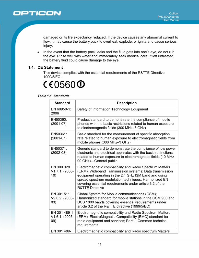
1.4. CE Statement This device complies with the essential requirements of the R&TTE Directive 1999/5/EC.
0560
Table 1-1. Standards
Standard Description
EN 60950-1: 2006
Safety of Information Technology Equipment
EN50360: (2001-07)
Product standard to demonstrate the compliance of mobile phones with the basic restrictions related to human exposure to electromagnetic fields (300 MHz–3 GHz)
EN50361: (2001-07)
Basic standard for the measurement of specific absorption rate related to human exposure to electromagnetic fields from mobile phones (300 MHz–3 GHz)
EN50371: (2002-03)
Generic standard to demonstrate the compliance of low power electronic and electrical apparatus with the basic restrictions related to human exposure to electromagnetic fields (10 MHz–00 GHz)—General public
EN 300 328 V1.7.1: (2006-10)
Electromagnetic compatibility and Radio Spectrum Matters (ERM); Wideband Transmission systems; Data transmission equipment operating in the 2.4 GHz ISM band and using spread spectrum modulation techniques; Harmonized EN covering essential requirements under article 3.2 of the R&TTE Directive
EN 301 511 V9.0.2: (2003-03)
Global System for Mobile communications (GSM); Harmonized standard for mobile stations in the GSM 900 and DCS 1800 bands covering essential requirements under article 3.2 of the R&TTE directive (1999/5/EC)
EN 301 489-1 V1.6.1: (2005-09)
Electromagnetic compatibility and Radio Spectrum Matters (ERM); ElectroMagnetic Compatibility (EMC) standard for radio equipment and services; Part 1: Common technical requirements
EN 301 489- Electromagnetic compatibility and Radio spectrum Matters
Opticon PHL 8000 series
User Manual
12
Standard Description 17 V1.2.1 (2002-08)
(ERM); ElectroMagnetic Compatibility (EMC) standard for radio equipment and services; Part 17: Specific conditions for 2,4 GHz wideband transmission systems and 5 GHz high performance RLAN equipment
EN 301 489-7 V1.2.1: (2002-08)
ElectroMagnetic compatibility and Radio spectrum Matters (ERM); ElectroMagnetic Compatibility (EMC) standard for radio equipment ad services; Part 7: Specific conditions for mobile and portable radio and ancillary equipment of digital cellular radio telecommunications systems (GSM and DCS).
This device is a 2.4 GHz wideband transmission system (transceiver), intended for use in all EU member states and EFTA countries, except in France and Italy, where restrictive use applies. In Italy the end-user should apply for a license at the national spectrum authorities in order to obtain authorization to use the device for setting up outdoor radio links and/or for supplying public access to telecommunications and/or network services. This device may not be used for setting up outdoor radio links in France and in some areas the RF output power may be limited to 10 mW EIRP in the frequency range of 2454–2483.5 MHz. For detailed information, the end-user should contact the national spectrum authority in France.
1.5. Federal Communication Commission (FCC) Statement This equipment has been tested and found to comply with the limits for a Class B digital device, pursuant to Part 15 of the FCC Rules. These limits are designed to provide reasonable protection against harmful interference in a residential installation. This equipment generates, uses, and can radiate radio frequency energy and, if not installed and used in accordance with the instructions, may cause harmful interference to radio communications. However, there is no guarantee that interference will not occur in a particular installation. If this equipment does cause harmful interference to radio or television reception, which can be determined by turning the equipment off and on, the user is encouraged to try to correct the interference by one of the following measures:
• Reorient or relocate the receiving antenna.
• Increase the separation between the equipment and receiver.
• Connect the equipment into an outlet on a circuit different from that to which the receiver is connected.
• Consult the dealer or an experienced radio/TV technician for help.
FCC Caution: Any changes or modifications not expressly approved by the party responsible for compliance could void the user's authority to operate this equipment.
This device complies with Part 15 of the FCC Rules. Operation is subject to the following two conditions: (1) This device may not cause harmful interference, and (2) this device must accept any interference received, including interference that may cause undesired

Opticon PHL 8000 series
User Manual
13
operation. Complies with 21 CFR 1040.10 and 1040.11 except for deviations pursuant to Laser Notice No. 50, dated June 24, 2007.
Important note: Radiation Exposure Statement This equipment complies with FCC radiation exposure limits set forth for an uncontrolled environment. End users must follow the specific operating instructions for satisfying RF exposure compliance. To maintain compliance with FCC RF exposure compliance requirements, please follow the operating instructions as documented in this manual.
This transmitter must not be co-located or operated in conjunction with any other antenna or transmitter.
The availability of some specific channels and/or operational frequency bands are country dependent and are firmware programmed at the factory to match the intended destination. The firmware setting is not accessible by the end user.
1.5.1. LED and Laser Safety Information • Class II LED/laser product
• Do not stare at the LED/laser or shine into eyes
• Do not allow young children to use the product without adult supervision
• Do not replace/repair the LED/laser; these are not user replaceable
• Do not shine the LED/laser on a reflective surface
1.6. Recycling & Disposal
Do not dispose of this product in household trash. For proper end-of-life treatment consult the Environmental Care section of www.opticon.com.
1.7. Regulatory Information
For CE, FCC, RoHS, and other Document of Conformities information, consult the Regulatory section of www.opticon.com.
Opticon PHL 8000 series
User Manual
14
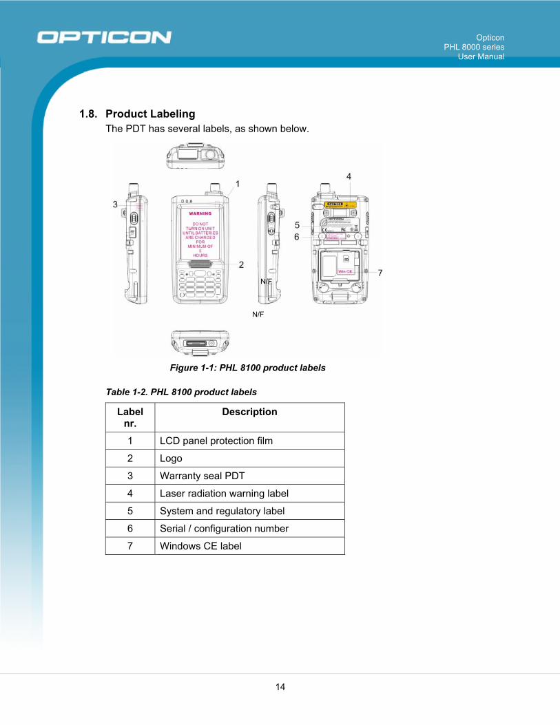
1.8. Product Labeling The PDT has several labels, as shown below.
Figure 1-1: PHL 8100 product labels
Table 1-2. PHL 8100 product labels
Label nr.
Description
1 LCD panel protection film
2 Logo
3 Warranty seal PDT
4 Laser radiation warning label
5 System and regulatory label
6 Serial / configuration number
7 Windows CE label
N/F
N/F
Opticon PHL 8000 series
User Manual
15
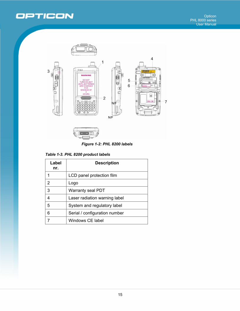
Figure 1-2: PHL 8200 labels
Table 1-3. PHL 8200 product labels
Label nr.
Description
1 LCD panel protection film
2 Logo
3 Warranty seal PDT
4 Laser radiation warning label
5 System and regulatory label
6 Serial / configuration number
7 Windows CE label
N/F
N/F
Opticon PHL 8000 series
User Manual
16
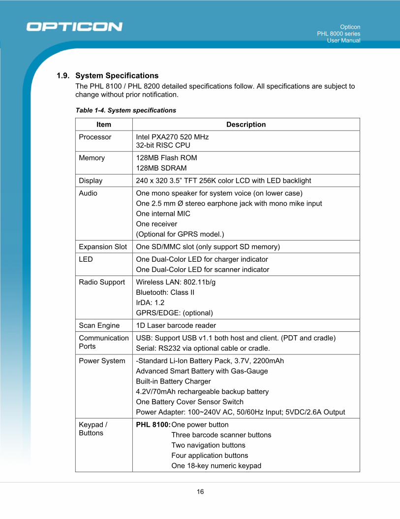
1.9. System Specifications The PHL 8100 / PHL 8200 detailed specifications follow. All specifications are subject to change without prior notification.
Table 1-4. System specifications
Item Description
Processor Intel PXA270 520 MHz 32-bit RISC CPU
Memory 128MB Flash ROM 128MB SDRAM
Display 240 x 320 3.5” TFT 256K color LCD with LED backlight
Audio One mono speaker for system voice (on lower case) One 2.5 mm Ø stereo earphone jack with mono mike input One internal MIC One receiver (Optional for GPRS model.)
Expansion Slot One SD/MMC slot (only support SD memory)
LED One Dual-Color LED for charger indicator One Dual-Color LED for scanner indicator
Radio Support Wireless LAN: 802.11b/g Bluetooth: Class II IrDA: 1.2 GPRS/EDGE: (optional)
Scan Engine 1D Laser barcode reader
Communication Ports
USB: Support USB v1.1 both host and client. (PDT and cradle) Serial: RS232 via optional cable or cradle.
Power System -Standard Li-Ion Battery Pack, 3.7V, 2200mAh Advanced Smart Battery with Gas-Gauge Built-in Battery Charger 4.2V/70mAh rechargeable backup battery One Battery Cover Sensor Switch Power Adapter: 100~240V AC, 50/60Hz Input; 5VDC/2.6A Output
Keypad / Buttons
PHL 8100: One power button Three barcode scanner buttons Two navigation buttons Four application buttons One 18-key numeric keypad
Opticon PHL 8000 series
User Manual
17
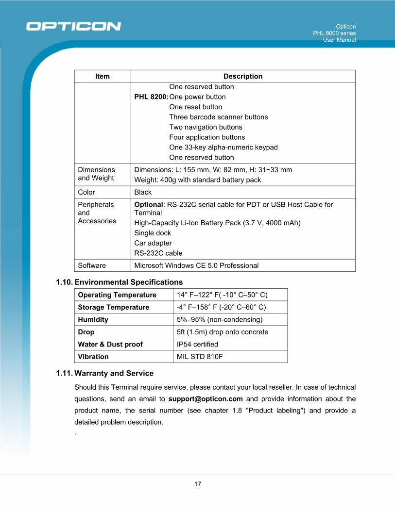
Item Description One reserved button PHL 8200: One power button One reset button Three barcode scanner buttons Two navigation buttons Four application buttons One 33-key alpha-numeric keypad One reserved button
Dimensions and Weight
Dimensions: L: 155 mm, W: 82 mm, H: 31~33 mm Weight: 400g with standard battery pack
Color Black
Peripherals and Accessories
Optional: RS-232C serial cable for PDT or USB Host Cable for Terminal High-Capacity Li-Ion Battery Pack (3.7 V, 4000 mAh) Single dock Car adapter RS-232C cable �
Software Microsoft Windows CE 5.0 Professional
1.10. Environmental Specifications Operating Temperature 14° F–122° F( -10° C–50° C)
Storage Temperature -4° F–158° F (-20° C–60° C)
Humidity 5%–95% (non-condensing)
Drop 5ft (1.5m) drop onto concrete
Water & Dust proof IP54 certified
Vibration MIL STD 810F
1.11. Warranty and Service
Should this Terminal require service, please contact your local reseller. In case of technical questions, send an email to [email protected] and provide information about the product name, the serial number (see chapter 1.8 "Product labeling") and provide a detailed problem description. .
Opticon PHL 8000 series
User Manual
18
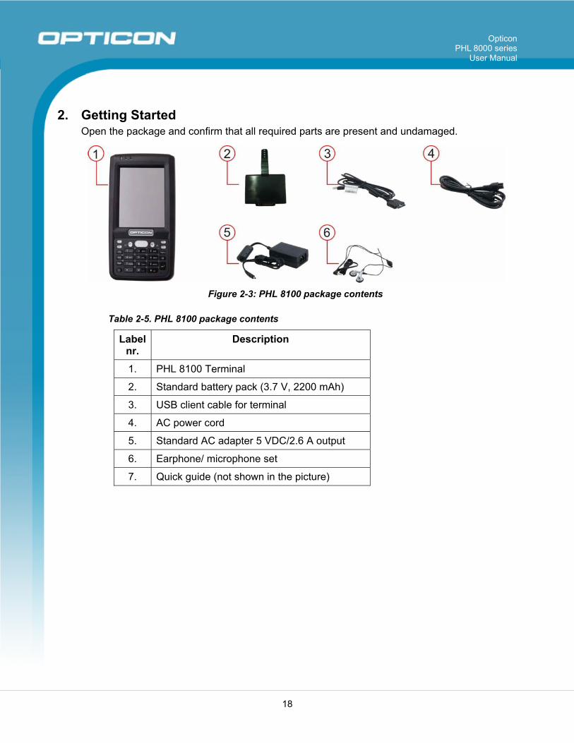
2. Getting Started Open the package and confirm that all required parts are present and undamaged.
Figure 2-3: PHL 8100 package contents
Table 2-5. PHL 8100 package contents
Label nr.
Description
1. PHL 8100 Terminal
2. Standard battery pack (3.7 V, 2200 mAh)
3. USB client cable for terminal
4. AC power cord
5. Standard AC adapter 5 VDC/2.6 A output
6. Earphone/ microphone set
7. Quick guide (not shown in the picture)
Opticon PHL 8000 series
User Manual
19
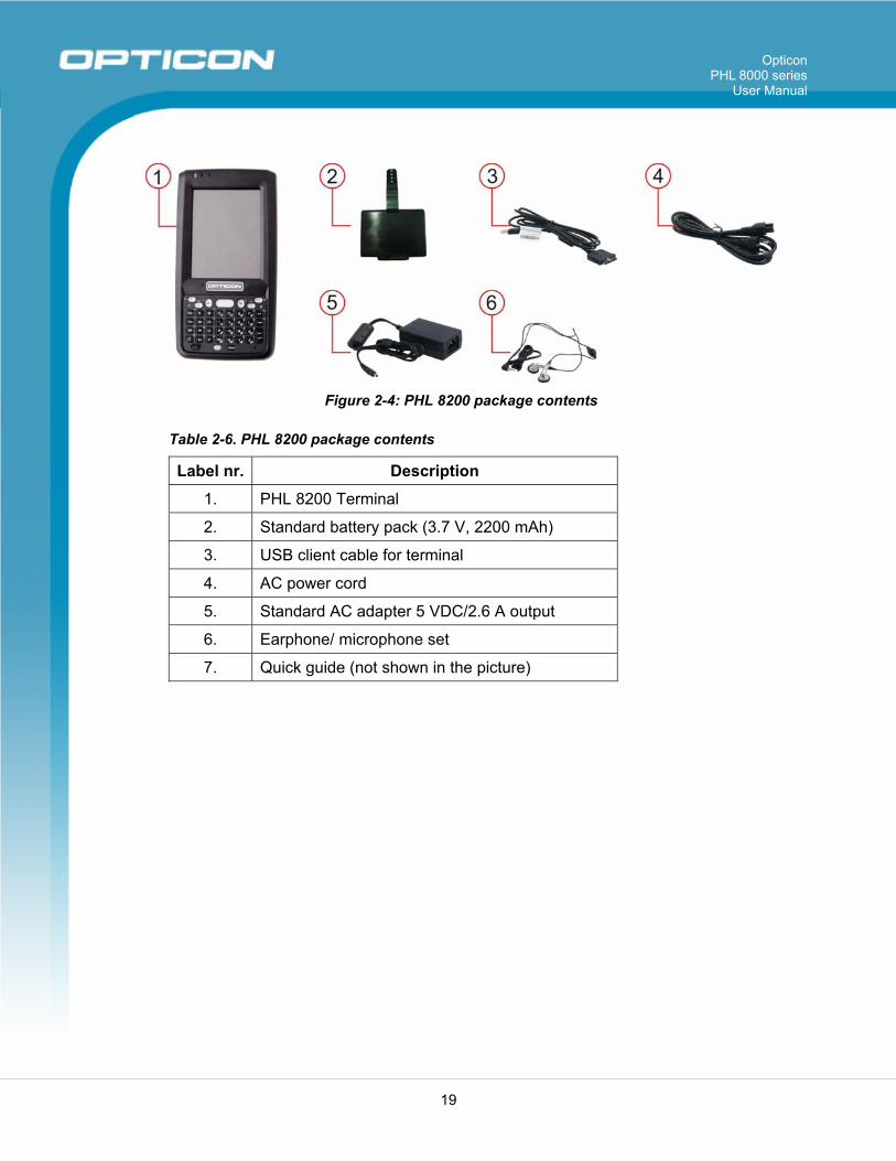
Figure 2-4: PHL 8200 package contents
Table 2-6. PHL 8200 package contents
Label nr. Description
1. PHL 8200 Terminal
2. Standard battery pack (3.7 V, 2200 mAh)
3. USB client cable for terminal
4. AC power cord
5. Standard AC adapter 5 VDC/2.6 A output
6. Earphone/ microphone set
7. Quick guide (not shown in the picture)

Opticon PHL 8000 series
User Manual
20
2.1. Product Overview
2.1.1. PHL 8100
Figure 2-5: PHL 8100 overview
Opticon PHL 8000 series
User Manual
21
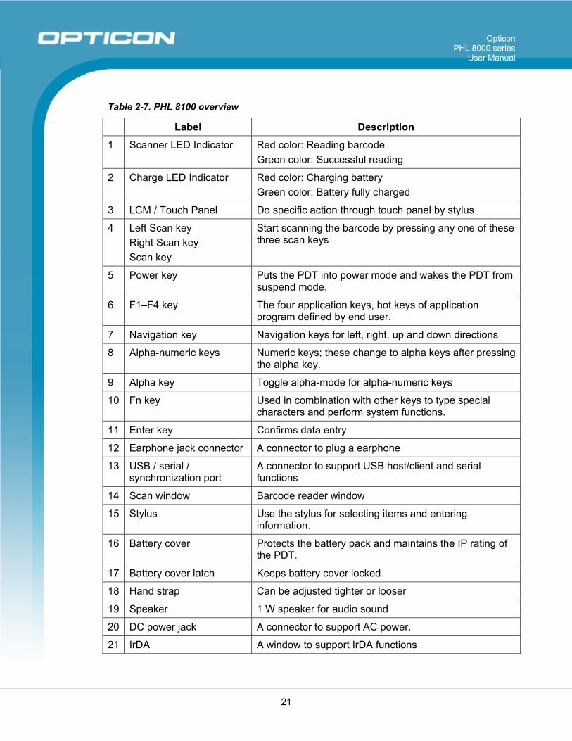
Table 2-7. PHL 8100 overview
Label Description
1 Scanner LED Indicator Red color: Reading barcode Green color: Successful reading
2 Charge LED Indicator Red color: Charging battery Green color: Battery fully charged
3 LCM / Touch Panel Do specific action through touch panel by stylus
4 Left Scan key Right Scan key Scan key
Start scanning the barcode by pressing any one of these three scan keys
5 Power key Puts the PDT into power mode and wakes the PDT from suspend mode.
6 F1–F4 key The four application keys, hot keys of application program defined by end user.
7 Navigation key Navigation keys for left, right, up and down directions
8 Alpha-numeric keys Numeric keys; these change to alpha keys after pressing the alpha key.
9 Alpha key Toggle alpha-mode for alpha-numeric keys
10 Fn key Used in combination with other keys to type special characters and perform system functions.
11 Enter key Confirms data entry
12 Earphone jack connector A connector to plug a earphone
13 USB / serial / synchronization port
A connector to support USB host/client and serial functions
14 Scan window Barcode reader window
15 Stylus Use the stylus for selecting items and entering information.
16 Battery cover Protects the battery pack and maintains the IP rating of the PDT.
17 Battery cover latch Keeps battery cover locked
18 Hand strap Can be adjusted tighter or looser
19 Speaker 1 W speaker for audio sound
20 DC power jack A connector to support AC power.
21 IrDA A window to support IrDA functions
Opticon PHL 8000 series
User Manual
22
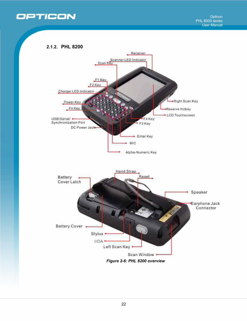
2.1.2. PHL 8200
Figure 2-6: PHL 8200 overview
Opticon PHL 8000 series
User Manual
23
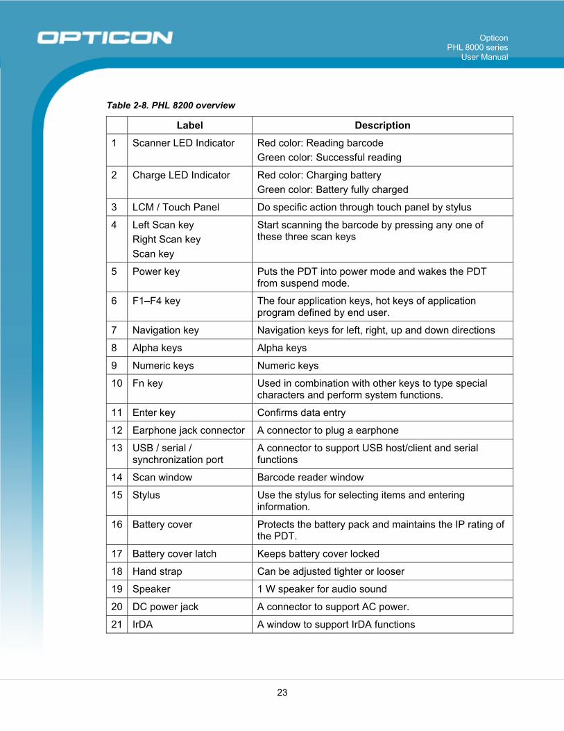
Table 2-8. PHL 8200 overview
Label Description
1 Scanner LED Indicator Red color: Reading barcode Green color: Successful reading
2 Charge LED Indicator Red color: Charging battery Green color: Battery fully charged
3 LCM / Touch Panel Do specific action through touch panel by stylus
4 Left Scan key Right Scan key Scan key
Start scanning the barcode by pressing any one of these three scan keys
5 Power key Puts the PDT into power mode and wakes the PDT from suspend mode.
6 F1–F4 key The four application keys, hot keys of application program defined by end user.
7 Navigation key Navigation keys for left, right, up and down directions
8 Alpha keys Alpha keys
9 Numeric keys Numeric keys
10 Fn key Used in combination with other keys to type special characters and perform system functions.
11 Enter key Confirms data entry
12 Earphone jack connector A connector to plug a earphone
13 USB / serial / synchronization port
A connector to support USB host/client and serial functions
14 Scan window Barcode reader window
15 Stylus Use the stylus for selecting items and entering information.
16 Battery cover Protects the battery pack and maintains the IP rating of the PDT.
17 Battery cover latch Keeps battery cover locked
18 Hand strap Can be adjusted tighter or looser
19 Speaker 1 W speaker for audio sound
20 DC power jack A connector to support AC power.
21 IrDA A window to support IrDA functions
Opticon PHL 8000 series
User Manual
24
2.2. Charging the Battery Pack Before using the PDT, charge the battery pack.
Charge time: The initial charge cycle for the battery pack is approximately 6 hours. Subsequent charging cycles are approximately 4 hours.
When charging the battery pack, the charging LED indicator on the PDT turns Red. After the battery pack is fully charged, the charging LED indicator turns Green.
CAUTION: Once you have charged the battery pack and backup battery and started using the PDT, do not leave the battery pack out of the PDT for too long, or any unsaved data will be lost. Power the PDT off if you want to change the main battery pack.
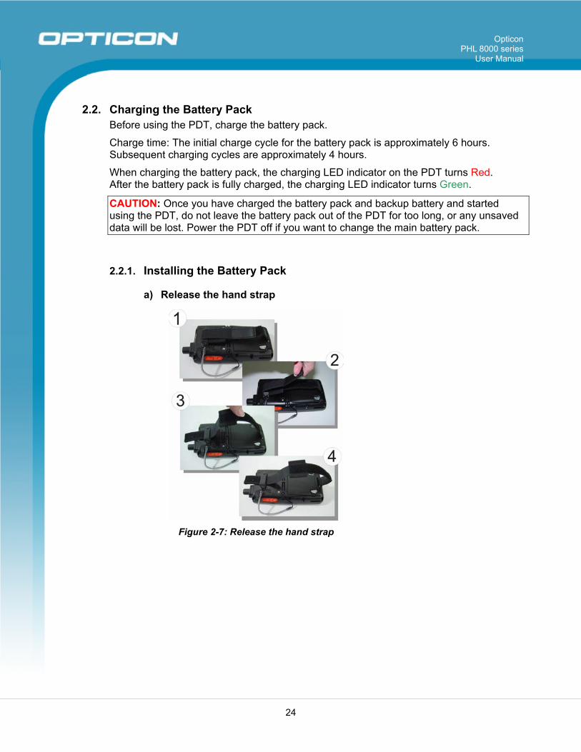
2.2.1. Installing the Battery Pack
a) Release the hand strap
Figure 2-7: Release the hand strap
Opticon PHL 8000 series
User Manual
25
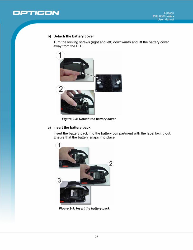
b) Detach the battery cover Turn the locking screws (right and left) downwards and lift the battery cover away from the PDT.
Figure 2-8: Detach the battery cover
c) Insert the battery pack Insert the battery pack into the battery compartment with the label facing out. Ensure that the battery snaps into place.
Figure 2-9: Insert the battery pack.
Opticon PHL 8000 series
User Manual
26
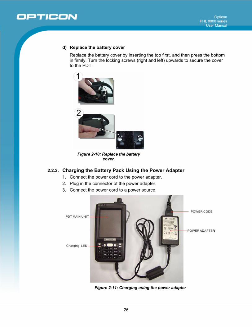
d) Replace the battery cover Replace the battery cover by inserting the top first, and then press the bottom in firmly. Turn the locking screws (right and left) upwards to secure the cover to the PDT.
Figure 2-10: Replace the battery
cover.
2.2.2. Charging the Battery Pack Using the Power Adapter 1. Connect the power cord to the power adapter. 2. Plug in the connector of the power adapter. 3. Connect the power cord to a power source.
Figure 2-11: Charging using the power adapter
Opticon PHL 8000 series
User Manual
27
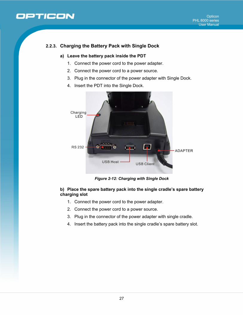
2.2.3. Charging the Battery Pack with Single Dock
a) Leave the battery pack inside the PDT 1. Connect the power cord to the power adapter.
2. Connect the power cord to a power source.
3. Plug in the connector of the power adapter with Single Dock.
4. Insert the PDT into the Single Dock.
Figure 2-12: Charging with Single Dock
b) Place the spare battery pack into the single cradle’s spare battery charging slot
1. Connect the power cord to the power adapter.
2. Connect the power cord to a power source.
3. Plug in the connector of the power adapter with single cradle.
4. Insert the battery pack into the single cradle’s spare battery slot.
Opticon PHL 8000 series
User Manual
28
2.3. Handling the PDT This section offers the basic procedures for using the PDT.
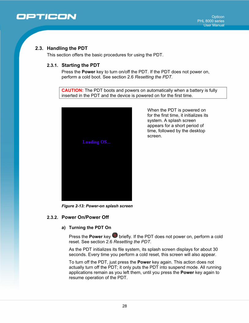
2.3.1. Starting the PDT Press the Power key to turn on/off the PDT. If the PDT does not power on, perform a cold boot. See section 2.6 Resetting the PDT.
CAUTION: The PDT boots and powers on automatically when a battery is fully inserted in the PDT and the device is powered on for the first time.
When the PDT is powered on for the first time, it initializes its system. A splash screen appears for a short period of time, followed by the desktop screen.
Figure 2-13: Power-on splash screen
2.3.2. Power On/Power Off
a) Turning the PDT On
Press the Power key briefly. If the PDT does not power on, perform a cold reset. See section 2.6 Resetting the PDT.
As the PDT initializes its file system, its splash screen displays for about 30 seconds. Every time you perform a cold reset, this screen will also appear.
To turn off the PDT, just press the Power key again. This action does not actually turn off the PDT; it only puts the PDT into suspend mode. All running applications remain as you left them, until you press the Power key again to resume operation of the PDT.
Opticon PHL 8000 series
User Manual
29
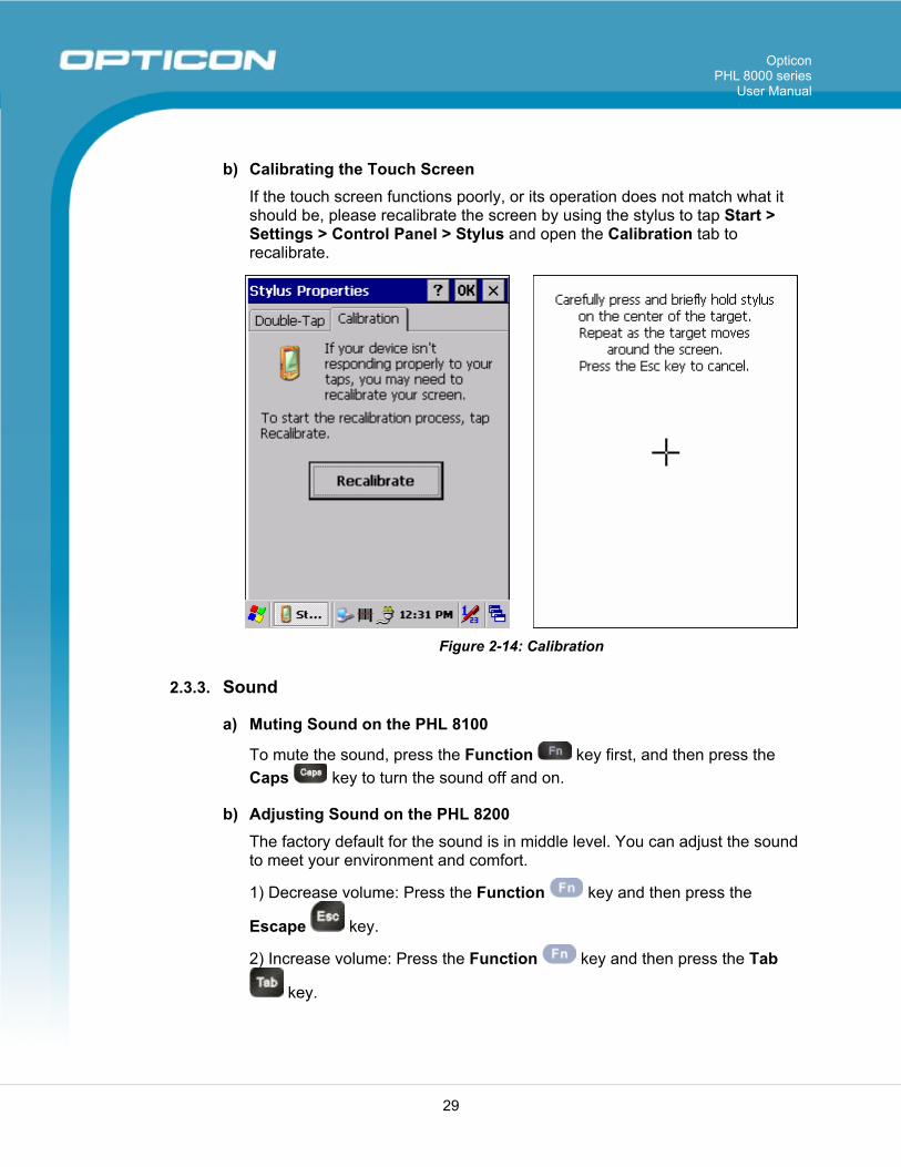
b) Calibrating the Touch Screen If the touch screen functions poorly, or its operation does not match what it should be, please recalibrate the screen by using the stylus to tap Start > Settings > Control Panel > Stylus and open the Calibration tab to recalibrate.
Figure 2-14: Calibration
2.3.3. Sound
a) Muting Sound on the PHL 8100
To mute the sound, press the Function key first, and then press the Caps key to turn the sound off and on.
b) Adjusting Sound on the PHL 8200 The factory default for the sound is in middle level. You can adjust the sound to meet your environment and comfort.
1) Decrease volume: Press the Function key and then press the
Escape key.
2) Increase volume: Press the Function key and then press the Tab
key.
Opticon PHL 8000 series
User Manual
30
2.3.4. Using the Stylus The stylus is located next to the hand strap on the left rear of the PDT. The stylus functions the same as the mouse on a PC. Use the stylus to: 1) Navigate the display, select menu items, and open optional applications. 2) Tap the characters on the soft keyboard panel. 3) Hold the stylus on the screen and drag it across the screen to select multiple items. CAUTION: Never use a pen, pencil, or other sharp object on the display; such items can damage the touch screen.
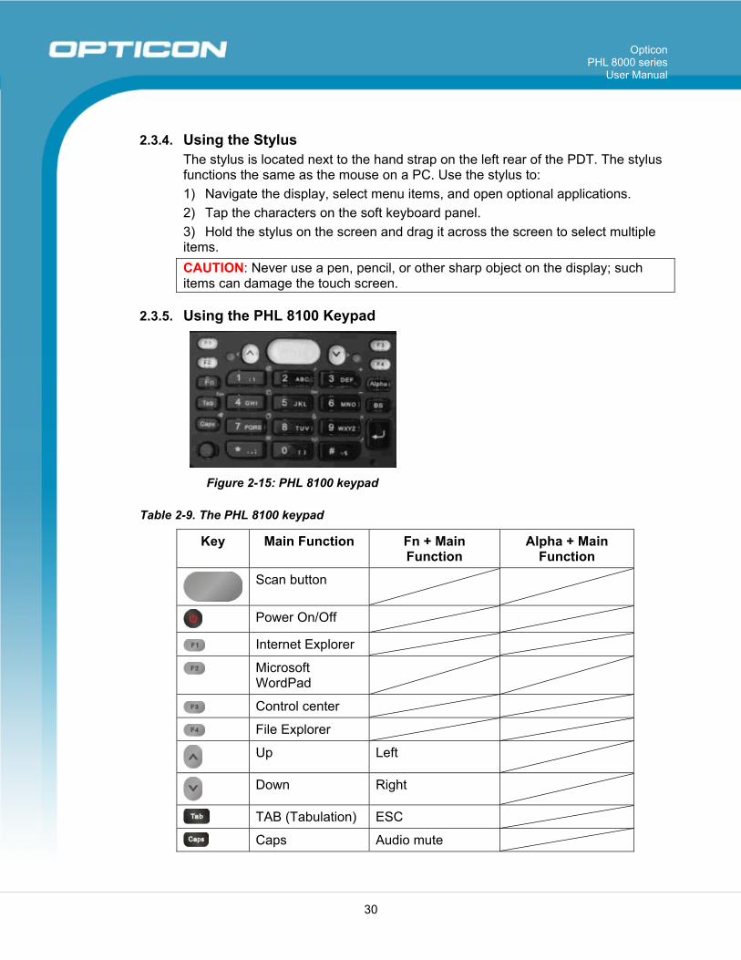
2.3.5. Using the PHL 8100 Keypad
Figure 2-15: PHL 8100 keypad
Table 2-9. The PHL 8100 keypad
Key Main Function Fn + Main Function
Alpha + Main Function
Scan button
Power On/Off
Internet Explorer
Microsoft WordPad
Control center
File Explorer
Up Left
Down Right
TAB (Tabulation) ESC
Caps Audio mute
Opticon PHL 8000 series
User Manual
31
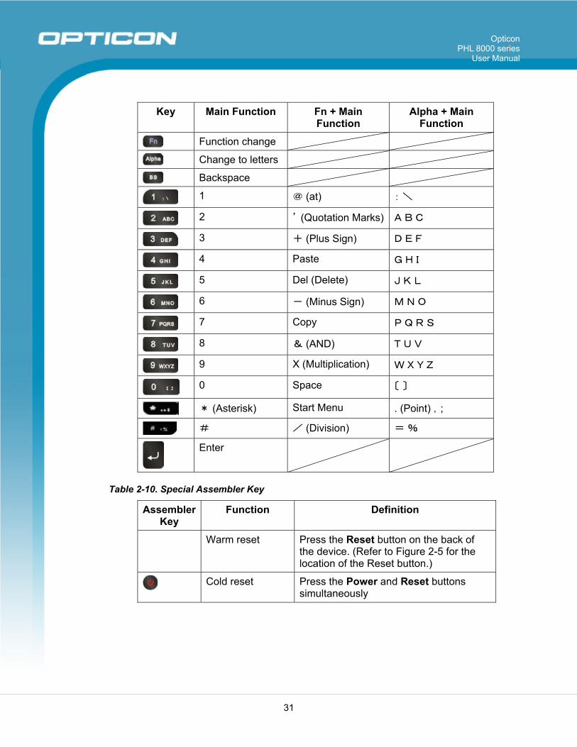
Key Main Function Fn + Main Function
Alpha + Main Function
Function change
Change to letters
Backspace
1 @ (at) : \
2 ’ (Quotation Marks) A B C
3 + (Plus Sign) D E F
4 Paste G H I
5 Del (Delete) J K L
6 - (Minus Sign) M N O
7 Copy P Q R S
8 & (AND) T U V
9 X (Multiplication) W X Y Z
0 Space 〔 〕
* (Asterisk) Start Menu . (Point) ,;
# / (Division) = %
Enter
Table 2-10. Special Assembler Key
Assembler Key
Function Definition
Warm reset Press the Reset button on the back of the device. (Refer to Figure 2-5 for the location of the Reset button.)
Cold reset Press the Power and Reset buttons simultaneously
Opticon PHL 8000 series
User Manual
32
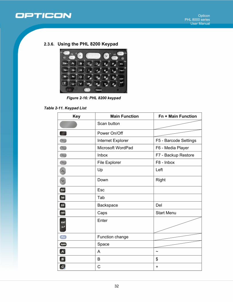
2.3.6. Using the PHL 8200 Keypad
Figure 2-16: PHL 8200 keypad
Table 2-11. Keypad List
Key Main Function Fn + Main Function
Scan button
Power On/Off
Internet Explorer F5 - Barcode Settings
Microsoft WordPad F6 - Media Player
Inbox F7 - Backup Restore
File Explorer F8 - Inbox
Up Left
Down Right
Esc
Tab
Backspace Del
Caps Start Menu
Enter
Function change
Space
A ~
B $
C +
Opticon PHL 8000 series
User Manual
33
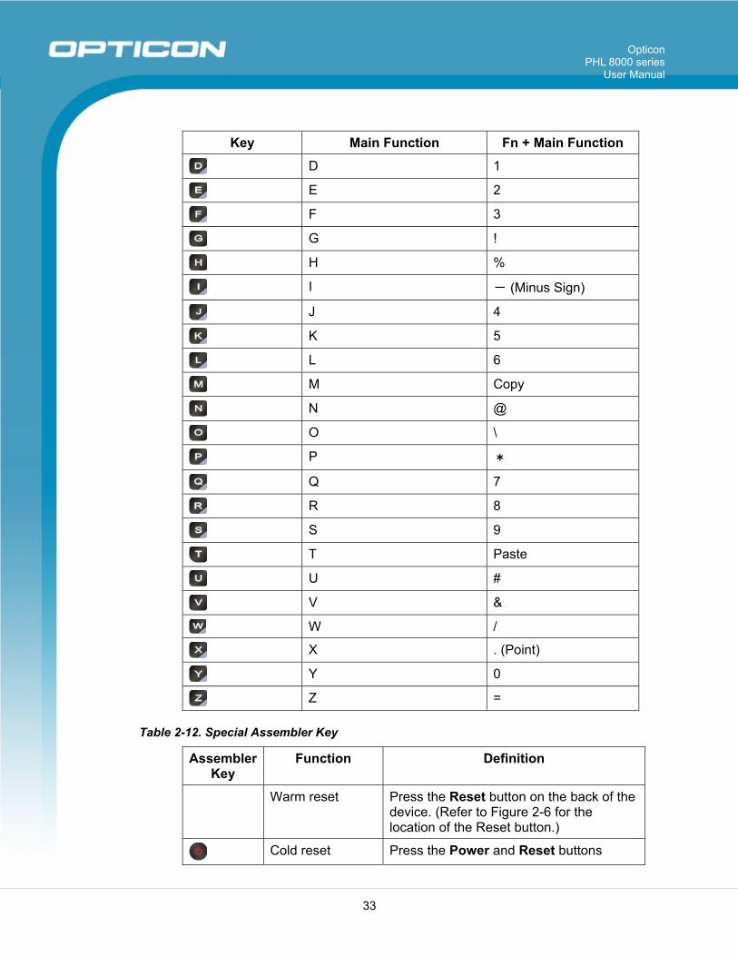
Key Main Function Fn + Main Function
D 1
E 2
F 3
G !
H %
I - (Minus Sign)
J 4
K 5
L 6
M Copy
N @
O \
P *
Q 7
R 8
S 9
T Paste
U #
V &
W /
X . (Point)
Y 0
Z =
Table 2-12. Special Assembler Key
Assembler Key
Function Definition
Warm reset Press the Reset button on the back of the device. (Refer to Figure 2-6 for the location of the Reset button.)
Cold reset Press the Power and Reset buttons
Opticon PHL 8000 series
User Manual
34
Assembler Key
Function Definition
simultaneously
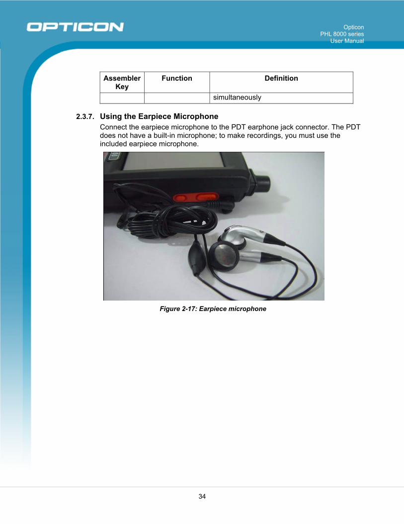
2.3.7. Using the Earpiece Microphone Connect the earpiece microphone to the PDT earphone jack connector. The PDT does not have a built-in microphone; to make recordings, you must use the included earpiece microphone.
Figure 2-17: Earpiece microphone
Opticon PHL 8000 series
User Manual
35
2.4. Navigating the Display
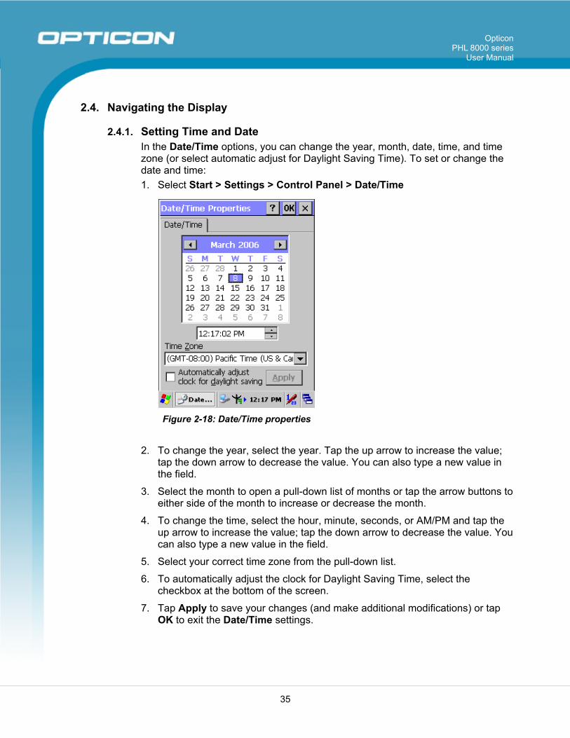
2.4.1. Setting Time and Date In the Date/Time options, you can change the year, month, date, time, and time zone (or select automatic adjust for Daylight Saving Time). To set or change the date and time: 1. Select Start > Settings > Control Panel > Date/Time
Figure 2-18: Date/Time properties
2. To change the year, select the year. Tap the up arrow to increase the value; tap the down arrow to decrease the value. You can also type a new value in the field.
3. Select the month to open a pull-down list of months or tap the arrow buttons to either side of the month to increase or decrease the month.
4. To change the time, select the hour, minute, seconds, or AM/PM and tap the up arrow to increase the value; tap the down arrow to decrease the value. You can also type a new value in the field.
5. Select your correct time zone from the pull-down list.
6. To automatically adjust the clock for Daylight Saving Time, select the checkbox at the bottom of the screen.
7. Tap Apply to save your changes (and make additional modifications) or tap OK to exit the Date/Time settings.
Opticon PHL 8000 series
User Manual
36
2.4.2. Entering Data To select and open programs, select Start > Programs from the task bar to open a list of available programs. Or, if the program has an icon on the desktop, double-tap to open it. There are several ways to enter data on the PDT within an application:
• Use the keypad to enter alpha-numeric characters. Refer to 2.3.5 Using the PHL 8100 Keypad or 2.3.6 Using the PHL 8200 Keypad.
• Use the stylus on the touch screen.
• Select text in the same way you select the text on a PC. Use the stylus to highlight the desired text by dragging the stylus across the desired text, double-tapping to select one word and triple-tapping to select an entire line/paragraph.
• Use the soft input panel (digital keyboard) with the stylus. Refer to 2.4.5 The Soft Keypad for more information.
• Use barcode scanning to enter data. Press the trigger or the Barcode Scan key to initiate a scan. The scanned data will enter the current application’s open file. Refer to 2.4.7 Reading Barcodes for more information on using a scanner.
For more information on factory installed applications, refer to Chapter 4, Software Programs.
2.4.3. The Command Bar Use the Command bar at top of the screen to perform tasks in programs, such as opening a file, or editing a file. Refer to Figure 2-19: The Command bar and Task bar to view the Command bar.
Opticon PHL 8000 series
User Manual
37
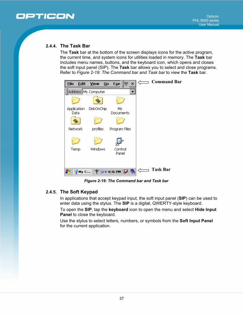
2.4.4. The Task Bar The Task bar at the bottom of the screen displays icons for the active program, the current time, and system icons for utilities loaded in memory. The Task bar includes menu names, buttons, and the keyboard icon, which opens and closes the soft input panel (SIP). The Task bar allows you to select and close programs. Refer to Figure 2-19: The Command bar and Task bar to view the Task bar.
Command Bar
Task Bar
Figure 2-19: The Command bar and Task bar
2.4.5. The Soft Keypad In applications that accept keypad input, the soft input panel (SIP) can be used to enter data using the stylus. The SIP is a digital, QWERTY-style keyboard. To open the SIP, tap the keyboard icon to open the menu and select Hide Input Panel to close the keyboard. Use the stylus to select letters, numbers, or symbols from the Soft Input Panel for the current application.
Opticon PHL 8000 series
User Manual
38
2.4.6. Setting Up Wireless LAN RF The Summit Client Utility (SCU) is an application designed for end users and administrators of mobile devices that use a Summit radio module. Using SCU, an end user can:
• Disable the radio (turn it off) and enable the radio (turn it on)
• View the contents of configuration profiles, or profiles, each of which houses the RF, security, and other settings for the radio
• Select the profile to be used to connect to a WLAN
• View global settings, which apply to every profile
• View status information on the radio, the access point (AP) or WLAN router to which it is connected, and the RF connection or link between the two
• To troubleshoot a connection or performance issue, view in-depth diagnostic information on the connection and the radio, and perform various troubleshooting and diagnostic tests
After logging on to the utility as an administrator, a user can perform these additional tasks:
• Create, rename, edit, and delete profiles
• Alter global settings, which apply to every profile
SCU provides a graphical user interface (GUI) for access to all of its functions. Access to these functions also is available through an application programming interface (API), which an application programmer can use to enable another utility to manage the radio. To initialize SCU:
• From the Start menu, select Programs.
• Select the directory called Summit.
• Inside the Summit directory are two items: a directory for the storage of security certificates and an SCU icon. To run SCU, double-click the SCU icon.
SCU has five tabs: Main, Profile, Status, Diags, and Global. Each tab is described in more detail in this section.
Opticon PHL 8000 series
User Manual
39
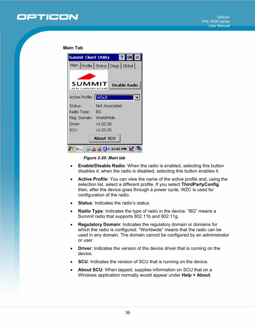
Main Tab
Figure 2-20: Main tab
• Enable/Disable Radio: When the radio is enabled, selecting this button disables it; when the radio is disabled, selecting this button enables it.
• Active Profile: You can view the name of the active profile and, using the selection list, select a different profile. If you select ThirdPartyConfig then, after the device goes through a power cycle, WZC is used for configuration of the radio.
• Status: Indicates the radio’s status.
• Radio Type: Indicates the type of radio in the device. “BG” means a Summit radio that supports 802.11b and 802.11g.
• Regulatory Domain: Indicates the regulatory domain or domains for which the radio is configured. “Worldwide” means that the radio can be used in any domain. The domain cannot be configured by an administrator or user.
• Driver: Indicates the version of the device driver that is running on the device.
• SCU: Indicates the version of SCU that is running on the device.
• About SCU: When tapped, supplies information on SCU that on a Windows application normally would appear under Help > About.
Opticon PHL 8000 series
User Manual
40
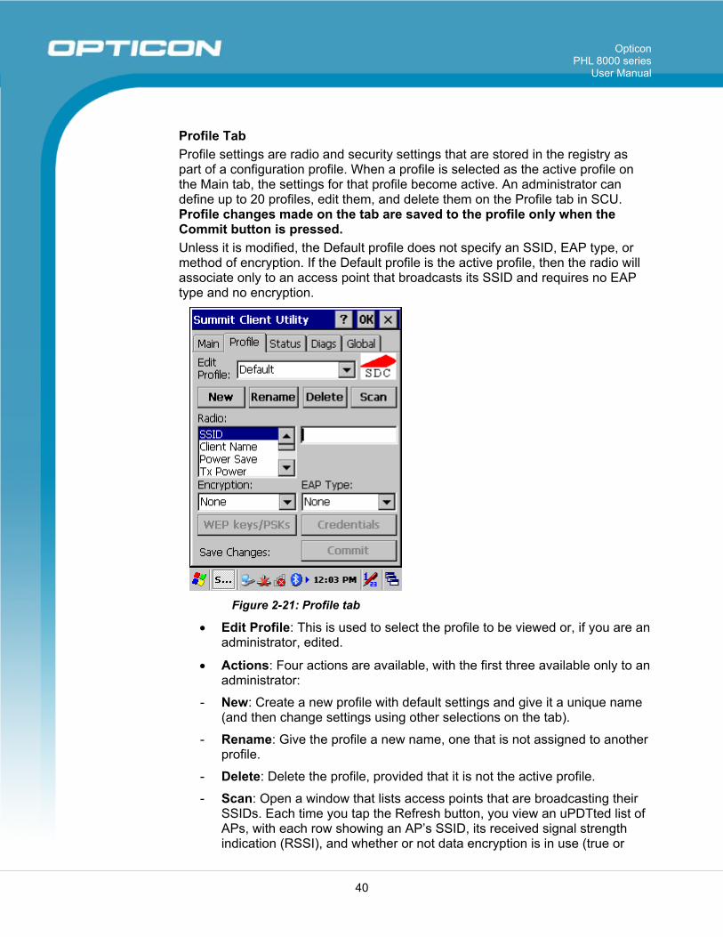
Profile Tab Profile settings are radio and security settings that are stored in the registry as part of a configuration profile. When a profile is selected as the active profile on the Main tab, the settings for that profile become active. An administrator can define up to 20 profiles, edit them, and delete them on the Profile tab in SCU. Profile changes made on the tab are saved to the profile only when the Commit button is pressed. Unless it is modified, the Default profile does not specify an SSID, EAP type, or method of encryption. If the Default profile is the active profile, then the radio will associate only to an access point that broadcasts its SSID and requires no EAP type and no encryption.
Figure 2-21: Profile tab
• Edit Profile: This is used to select the profile to be viewed or, if you are an administrator, edited.
• Actions: Four actions are available, with the first three available only to an administrator:
- New: Create a new profile with default settings and give it a unique name (and then change settings using other selections on the tab).
- Rename: Give the profile a new name, one that is not assigned to another profile.
- Delete: Delete the profile, provided that it is not the active profile.
- Scan: Open a window that lists access points that are broadcasting their SSIDs. Each time you tap the Refresh button, you view an uPDTted list of APs, with each row showing an AP’s SSID, its received signal strength indication (RSSI), and whether or not data encryption is in use (true or
Opticon PHL 8000 series
User Manual
41
false). You can sort the list by clicking on the column headers. If you are authorized as an administrator, select an SSID in the list, and tap Commit, you return to the Profile tab to create a profile for that SSID.
• Radio: Radio attributes in the list box can be selected individually. When an attribute is selected, the current setting or an appropriate selection box with the current setting highlighted appears on the right.
• Security: Values for the two primary security attributes, EAP type and encryption type, are displayed in separate dropdown lists, with the current values highlighted. When you as an administrator select an EAP type, the Credentials button appears; when you tap it, a dialog box appears that enables you to define authentication credentials for that EAP type. When you as an administrator select an encryption type that requires the definition of WEP keys or a pre-shared key, the PSKs/WEP Keys button appears; when you tap it, a dialog box appears that enables you to define WEP keys or a PSK.
• Commit: To ensure that changes to profile settings made on the tab are saved in the profile, you must tap the Commit button.
To cause a Summit radio to connect to a typical business WLAN, you must select a profile that specifies the SSID, EAP type, and encryption type supported by the WLAN:
• SSID: This is the name or identification of the WLAN.
• EAP type: This is the protocol used to authenticate the device and its user if the WLAN uses the Enterprise version of Wi-Fi Protected Access (WPA) and WPA2. SCU supports five EAP types: PEAP with EAP-MSCHAP (PEAP-MSCHAP), PEAP with EAP-GTC (PEAP-GTC), EAP-TLS, LEAP, and EAP-FAST.
• Encryption: This specifies the type of key used to encrypt and decrypt transmitted data and how that key is specified or derived. Encryption options include:
- WPA2 or WPA with dynamic keys (derived from the EAP authentication process)
- WPA2 or WPA with pre-shared keys
- Static WEP keys
Consult the Summit Client Utility User’s Guide for details on all profile settings, including security settings.
Opticon PHL 8000 series
User Manual
42
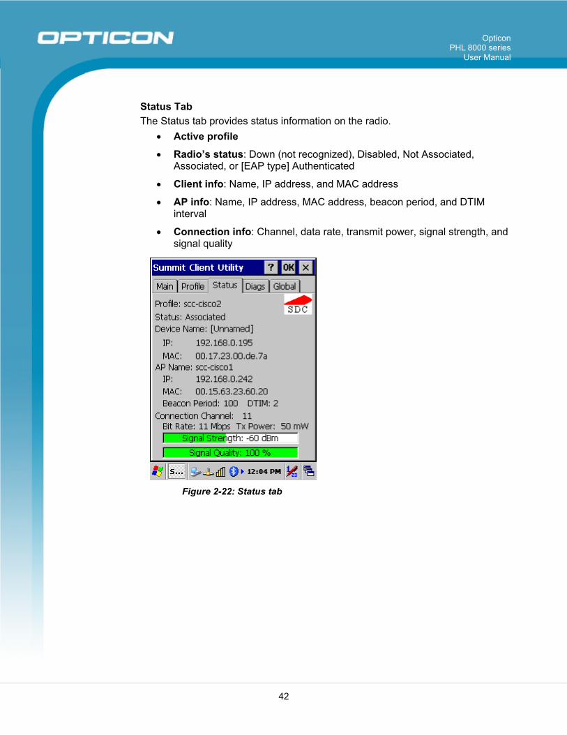
Status Tab The Status tab provides status information on the radio.
• Active profile
• Radio’s status: Down (not recognized), Disabled, Not Associated, Associated, or [EAP type] Authenticated
• Client info: Name, IP address, and MAC address
• AP info: Name, IP address, MAC address, beacon period, and DTIM interval
• Connection info: Channel, data rate, transmit power, signal strength, and signal quality
Figure 2-22: Status tab
Opticon PHL 8000 series
User Manual
43
Diags Tab
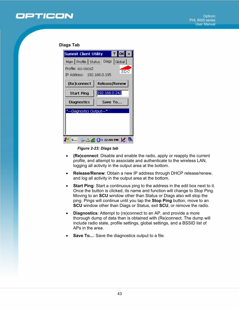
Figure 2-23: Diags tab
• (Re)connect: Disable and enable the radio, apply or reapply the current profile, and attempt to associate and authenticate to the wireless LAN, logging all activity in the output area at the bottom.
• Release/Renew: Obtain a new IP address through DHCP release/renew, and log all activity in the output area at the bottom.
• Start Ping: Start a continuous ping to the address in the edit box next to it. Once the button is clicked, its name and function will change to Stop Ping. Moving to an SCU window other than Status or Diags also will stop the ping. Pings will continue until you tap the Stop Ping button, move to an SCU window other than Diags or Status, exit SCU, or remove the radio.
• Diagnostics: Attempt to (re)connect to an AP, and provide a more thorough dump of data than is obtained with (Re)connect. The dump will include radio state, profile settings, global settings, and a BSSID list of APs in the area.
• Save To...: Save the diagnostics output to a file.
Opticon PHL 8000 series
User Manual
44
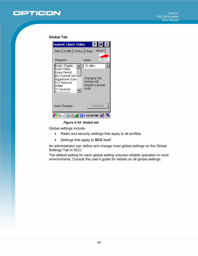
Global Tab
Figure 2-24: Global tab
Global settings include: • Radio and security settings that apply to all profiles
• Settings that apply to SCU itself
An administrator can define and change most global settings on the Global Settings Tab in SCU. The default setting for each global setting ensures reliable operation in most environments. Consult the user’s guide for details on all global settings.
Opticon PHL 8000 series
User Manual
45
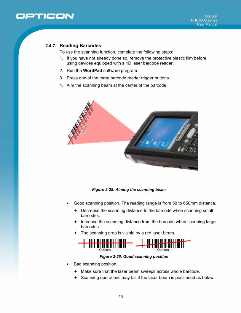
2.4.7. Reading Barcodes To use the scanning function, complete the following steps: 1. If you have not already done so, remove the protective plastic film before
using devices equipped with a 1D laser barcode reader.
2. Run the WordPad software program.
3. Press one of the three barcode reader trigger buttons.
4. Aim the scanning beam at the center of the barcode.
Figure 2-25: Aiming the scanning beam
• Good scanning position. The reading range is from 50 to 650mm distance.
Decrease the scanning distance to the barcode when scanning small barcodes.
Increase the scanning distance from the barcode when scanning large barcodes.
The scanning area is visible by a red laser beam.
Figure 2-26: Good scanning position
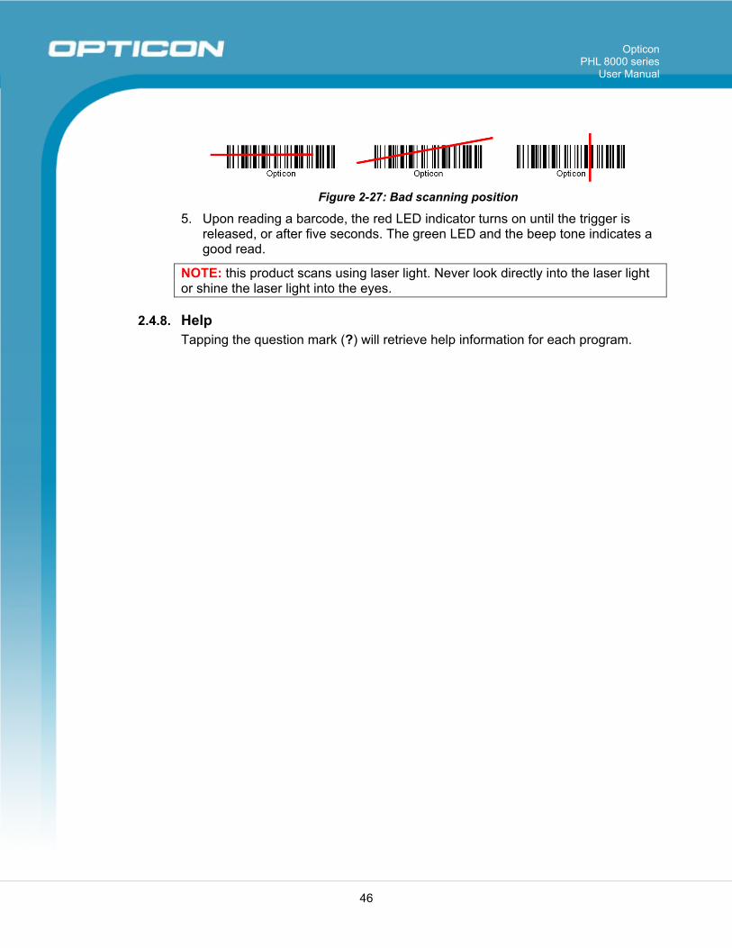
• Bad scanning position.
Make sure that the laser beam sweeps across whole barcode. Scanning operations may fail if the laser beam is positioned as below.
Opticon PHL 8000 series
User Manual
46
Figure 2-27: Bad scanning position
5. Upon reading a barcode, the red LED indicator turns on until the trigger is released, or after five seconds. The green LED and the beep tone indicates a good read.
NOTE: this product scans using laser light. Never look directly into the laser light or shine the laser light into the eyes.
2.4.8. Help Tapping the question mark (?) will retrieve help information for each program.
Opticon PHL 8000 series
User Manual
47
2.5. Power Management
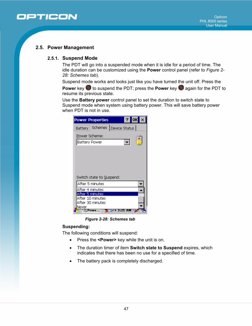
2.5.1. Suspend Mode The PDT will go into a suspended mode when it is idle for a period of time. The idle duration can be customized using the Power control panel (refer to Figure 2-28: Schemes tab). Suspend mode works and looks just like you have turned the unit off. Press the Power key to suspend the PDT; press the Power key again for the PDT to resume its previous state. Use the Battery power control panel to set the duration to switch state to Suspend mode when system using battery power. This will save battery power when PDT is not in use.
Figure 2-28: Schemes tab
Suspending: The following conditions will suspend:
• Press the <Power> key while the unit is on.
• The duration timer of item Switch state to Suspend expires, which indicates that there has been no use for a specified of time.
• The battery pack is completely discharged.
Opticon PHL 8000 series
User Manual
48
2.5.2. Resuming Use one of following methods to resume (wake up the PDT):
• Press the <Power> key to suspend or resume (wake up).
• Put the PDT into a dock.
When a battery pack completely discharges while the unit is in suspend mode, the PDT remains suspended until the discharged battery condition is corrected.
2.6. Resetting the PDT
2.6.1. Soft (Warm) Reset A warm reset is a transition from the on, idle, or suspend power state that closes all applications and clears the working RAM, but preserves the file system. Reason for a Warm Reset: If an application “hangs,” initiate a warm reset to terminate the application only. Process for a Warm Reset: Press the Reset button on the back of the PDT. After a Warm Reset:
• The desktop appears with the application shortcuts on the screen.
• The custom settings in the registry are persistent.
2.6.2. Hard (Cold) Reset 1. You can use a Cold Reset to initiate the device if WINCE.NET OS locks up or
Warm Reset does not work
2. To perform a Cold Reset, press the Power button on the front and the Reset button on the back simultaneously.
3. The device will reboot after a Cold Reset.
CAUTION: It is best to use only the warm reset. Try a warm reset before you initiate a cold reset. All applications will be closed and working RAM and all files will be cleared if you initiate a cold reset. Before a cold reset, back up your files to Flash ROM, Flash Card, or PC.
Opticon PHL 8000 series
User Manual
49
3. Settings 3.1. Introduction
To view available options for the PDT ’s settings, tap Start > Settings. There are three items inside Settings: Control Panel, Network and Dial-up, and Taskbar and Start.
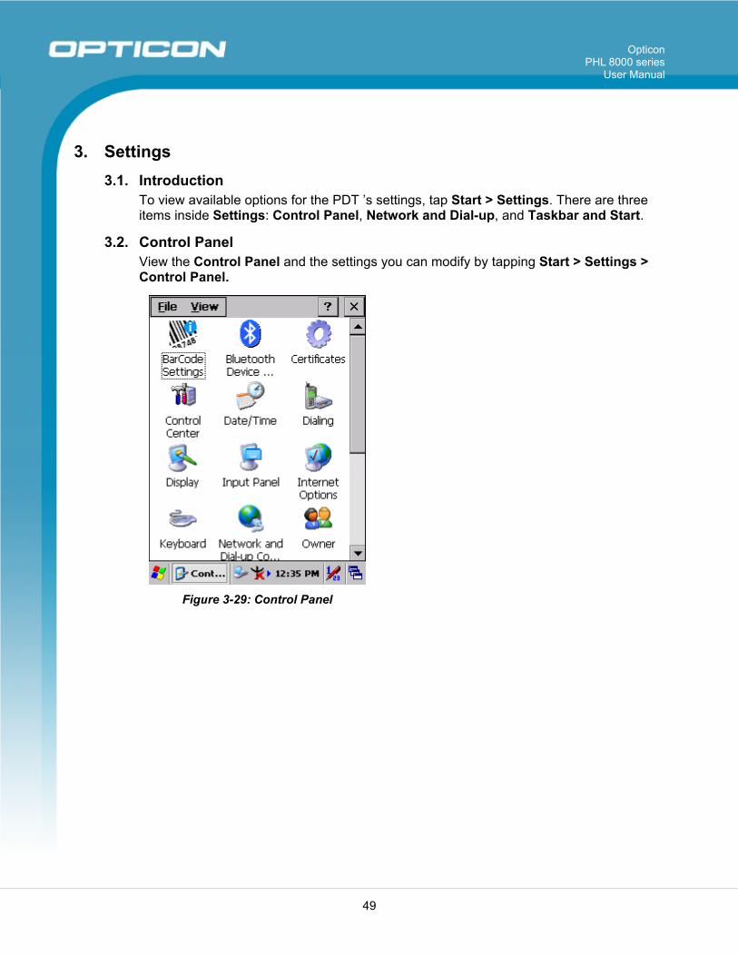
3.2. Control Panel View the Control Panel and the settings you can modify by tapping Start > Settings > Control Panel.
Figure 3-29: Control Panel
Opticon PHL 8000 series
User Manual
50
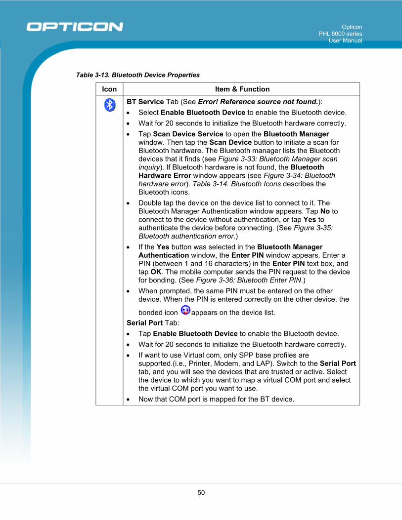
Table 3-13. Bluetooth Device Properties
Icon Item & Function
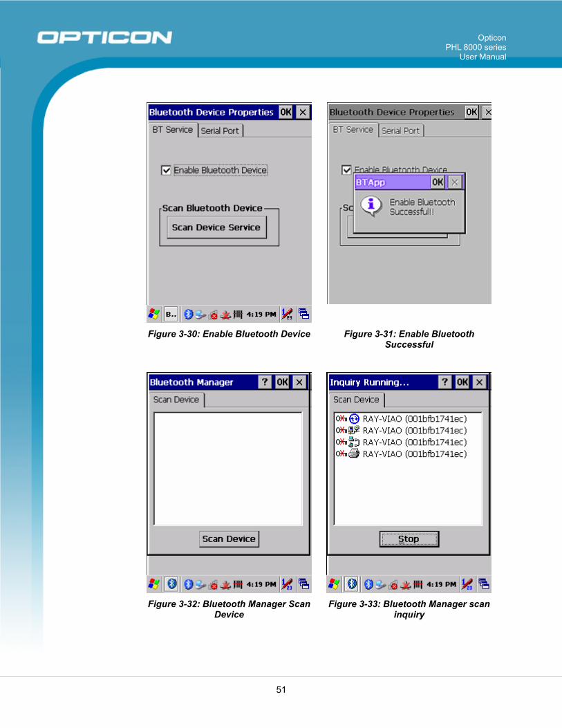
BT Service Tab (See Error! Reference source not found.): • Select Enable Bluetooth Device to enable the Bluetooth device. • Wait for 20 seconds to initialize the Bluetooth hardware correctly. • Tap Scan Device Service to open the Bluetooth Manager
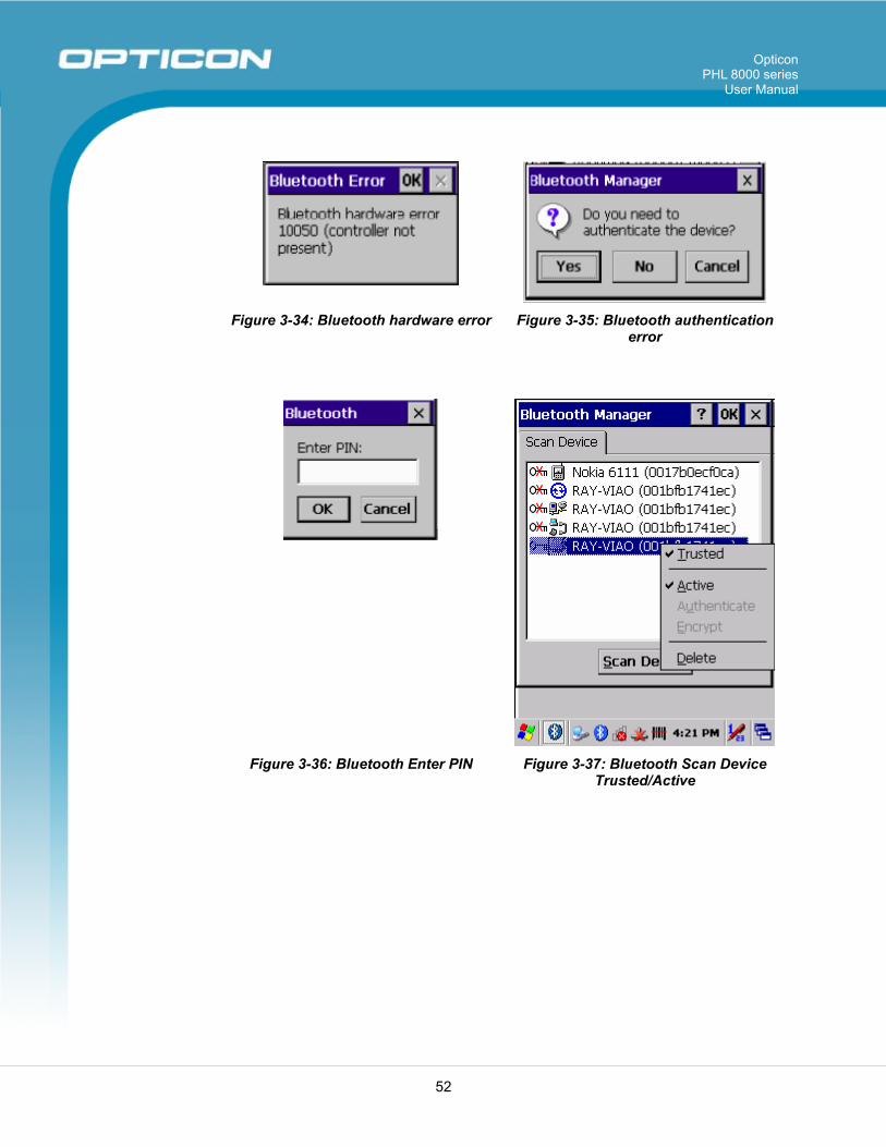
window. Then tap the Scan Device button to initiate a scan for Bluetooth hardware. The Bluetooth manager lists the Bluetooth devices that it finds (see Figure 3-33: Bluetooth Manager scan inquiry). If Bluetooth hardware is not found, the Bluetooth Hardware Error window appears (see Figure 3-34: Bluetooth hardware error). Table 3-14. Bluetooth Icons describes the Bluetooth icons.
• Double tap the device on the device list to connect to it. The Bluetooth Manager Authentication window appears. Tap No to connect to the device without authentication, or tap Yes to authenticate the device before connecting. (See Figure 3-35: Bluetooth authentication error.)
• If the Yes button was selected in the Bluetooth Manager Authentication window, the Enter PIN window appears. Enter a PIN (between 1 and 16 characters) in the Enter PIN text box, and tap OK. The mobile computer sends the PIN request to the device for bonding. (See Figure 3-36: Bluetooth Enter PIN.)
• When prompted, the same PIN must be entered on the other device. When the PIN is entered correctly on the other device, the
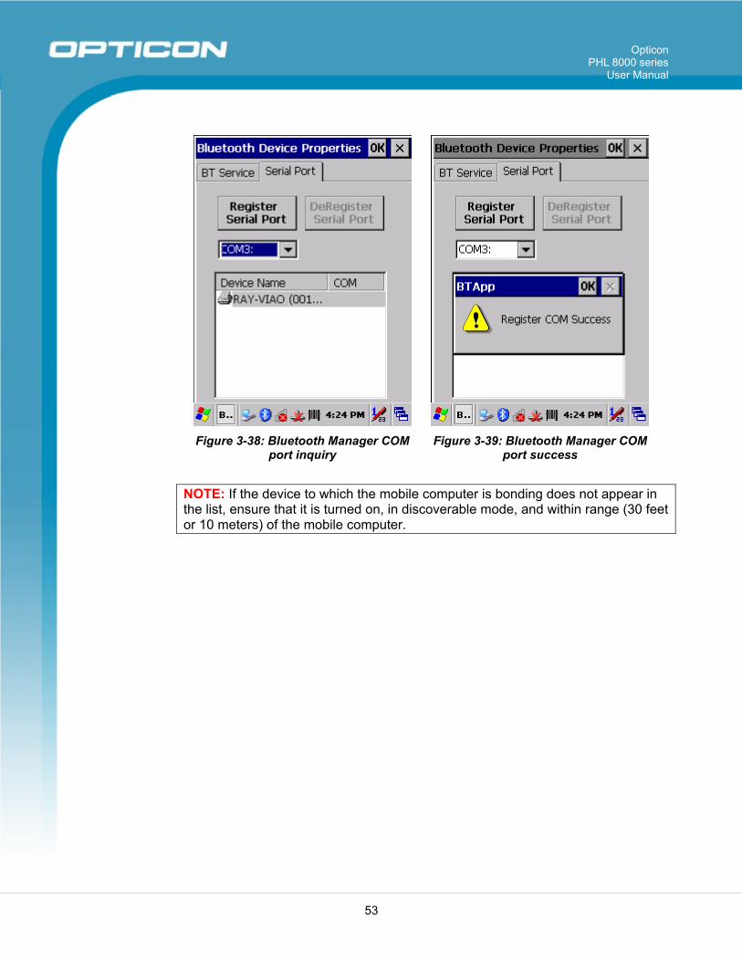
bonded icon appears on the device list. Serial Port Tab: • Tap Enable Bluetooth Device to enable the Bluetooth device. • Wait for 20 seconds to initialize the Bluetooth hardware correctly. • If want to use Virtual com, only SPP base profiles are
supported.(i.e., Printer, Modem, and LAP). Switch to the Serial Port tab, and you will see the devices that are trusted or active. Select the device to which you want to map a virtual COM port and select the virtual COM port you want to use.
• Now that COM port is mapped for the BT device.
Opticon PHL 8000 series
User Manual
51
Figure 3-30: Enable Bluetooth Device Figure 3-31: Enable Bluetooth Successful
Figure 3-32: Bluetooth Manager Scan
Device Figure 3-33: Bluetooth Manager scan
inquiry
Opticon PHL 8000 series
User Manual
52
Figure 3-34: Bluetooth hardware error Figure 3-35: Bluetooth authentication error
Figure 3-36: Bluetooth Enter PIN Figure 3-37: Bluetooth Scan Device
Trusted/Active
Opticon PHL 8000 series
User Manual
53
Figure 3-38: Bluetooth Manager COM
port inquiry Figure 3-39: Bluetooth Manager COM
port success NOTE: If the device to which the mobile computer is bonding does not appear in the list, ensure that it is turned on, in discoverable mode, and within range (30 feet or 10 meters) of the mobile computer.
Opticon PHL 8000 series
User Manual
54
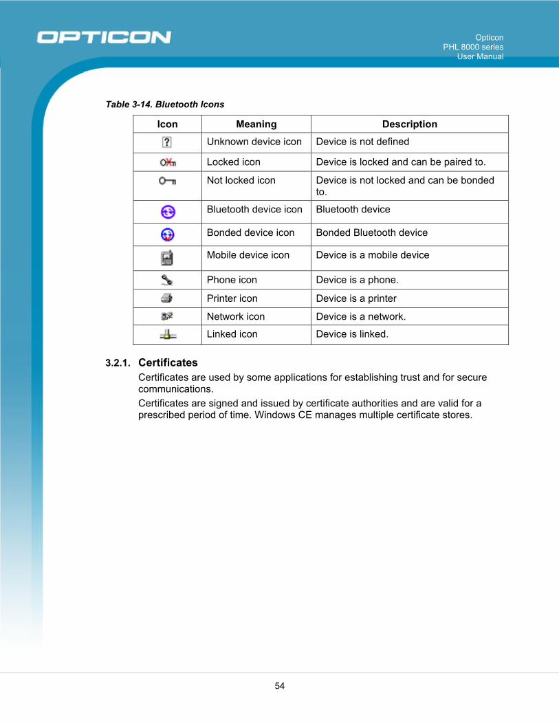
Table 3-14. Bluetooth Icons
Icon Meaning Description
Unknown device icon Device is not defined
Locked icon Device is locked and can be paired to.
Not locked icon Device is not locked and can be bonded to.
Bluetooth device icon Bluetooth device
Bonded device icon Bonded Bluetooth device
Mobile device icon Device is a mobile device
Phone icon Device is a phone.
Printer icon Device is a printer
Network icon Device is a network.
Linked icon Device is linked.
3.2.1. Certificates Certificates are used by some applications for establishing trust and for secure communications. Certificates are signed and issued by certificate authorities and are valid for a prescribed period of time. Windows CE manages multiple certificate stores.
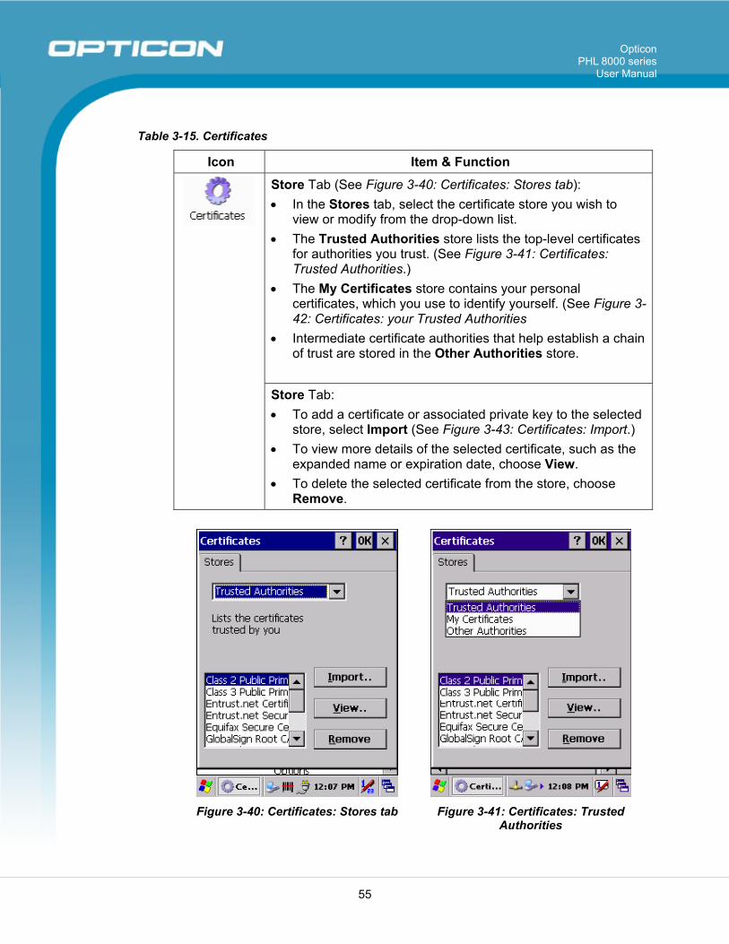
Opticon PHL 8000 series
User Manual
55
Table 3-15. Certificates
Icon Item & Function
Store Tab (See Figure 3-40: Certificates: Stores tab): • In the Stores tab, select the certificate store you wish to
view or modify from the drop-down list. • The Trusted Authorities store lists the top-level certificates
for authorities you trust. (See Figure 3-41: Certificates: Trusted Authorities.)
• The My Certificates store contains your personal certificates, which you use to identify yourself. (See Figure 3-42: Certificates: your Trusted Authorities
• Intermediate certificate authorities that help establish a chain of trust are stored in the Other Authorities store.
Store Tab: • To add a certificate or associated private key to the selected
store, select Import (See Figure 3-43: Certificates: Import.) • To view more details of the selected certificate, such as the
expanded name or expiration date, choose View. • To delete the selected certificate from the store, choose
Remove.
Figure 3-40: Certificates: Stores tab Figure 3-41: Certificates: Trusted
Authorities
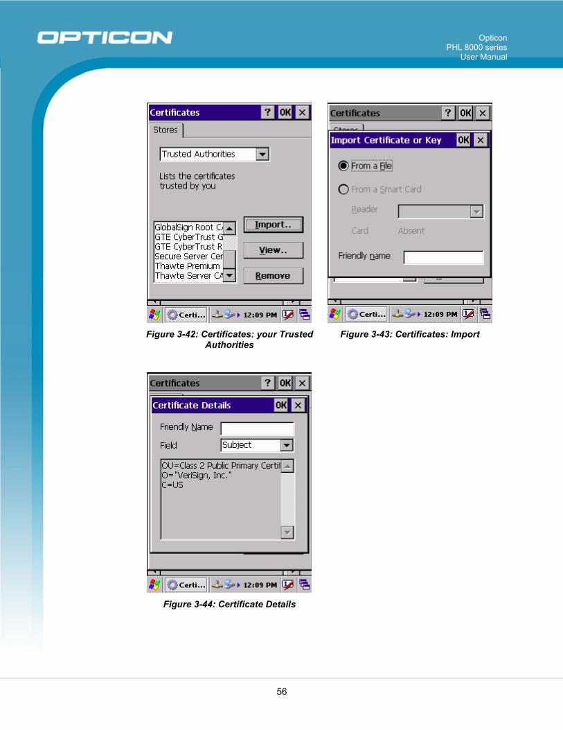
Opticon PHL 8000 series
User Manual
56
Figure 3-42: Certificates: your Trusted
Authorities Figure 3-43: Certificates: Import
Figure 3-44: Certificate Details
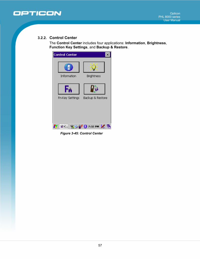
Opticon PHL 8000 series
User Manual
57
3.2.2. Control Center The Control Center includes four applications: Information, Brightness, Function Key Settings, and Backup & Restore.
Figure 3-45: Control Center
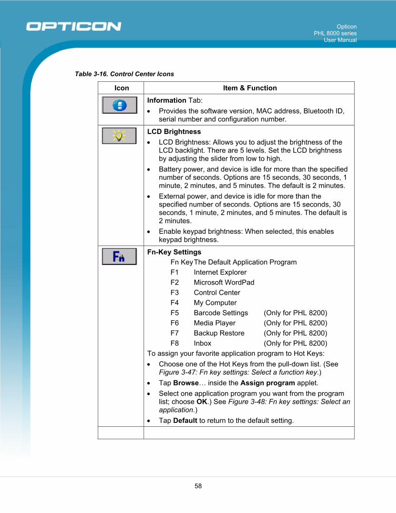
Opticon PHL 8000 series
User Manual
58
Table 3-16. Control Center Icons
Icon Item & Function
Information Tab: • Provides the software version, MAC address, Bluetooth ID,
serial number and configuration number.
LCD Brightness • LCD Brightness: Allows you to adjust the brightness of the
LCD backlight. There are 5 levels. Set the LCD brightness by adjusting the slider from low to high.
• Battery power, and device is idle for more than the specified number of seconds. Options are 15 seconds, 30 seconds, 1 minute, 2 minutes, and 5 minutes. The default is 2 minutes.
• External power, and device is idle for more than the specified number of seconds. Options are 15 seconds, 30 seconds, 1 minute, 2 minutes, and 5 minutes. The default is 2 minutes.
• Enable keypad brightness: When selected, this enables keypad brightness.
Fn-Key Settings Fn Key The Default Application Program F1 Internet Explorer F2 Microsoft WordPad F3 Control Center F4 My Computer F5 Barcode Settings (Only for PHL 8200) F6 Media Player (Only for PHL 8200) F7 Backup Restore (Only for PHL 8200) F8 Inbox (Only for PHL 8200) To assign your favorite application program to Hot Keys: • Choose one of the Hot Keys from the pull-down list. (See
Figure 3-47: Fn key settings: Select a function key.) • Tap Browse… inside the Assign program applet. • Select one application program you want from the program
list; choose OK.) See Figure 3-48: Fn key settings: Select an application.)
• Tap Default to return to the default setting.
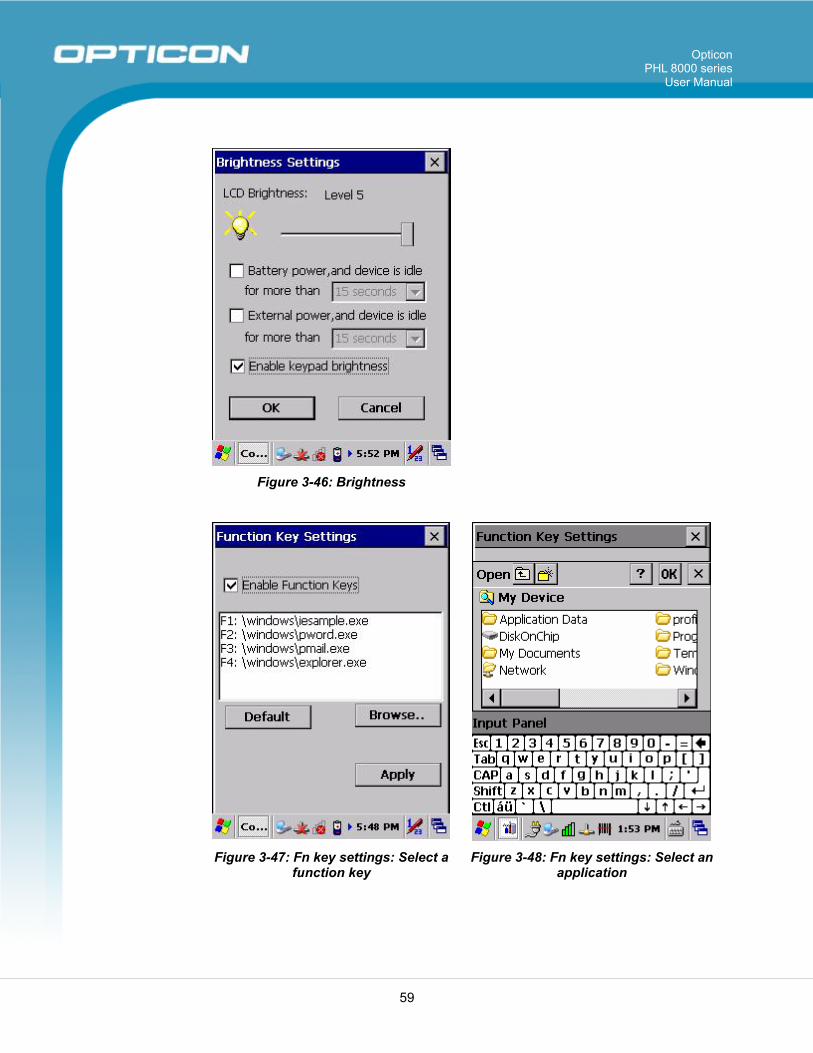
Opticon PHL 8000 series
User Manual
59
Figure 3-46: Brightness
Figure 3-47: Fn key settings: Select a
function key Figure 3-48: Fn key settings: Select an
application
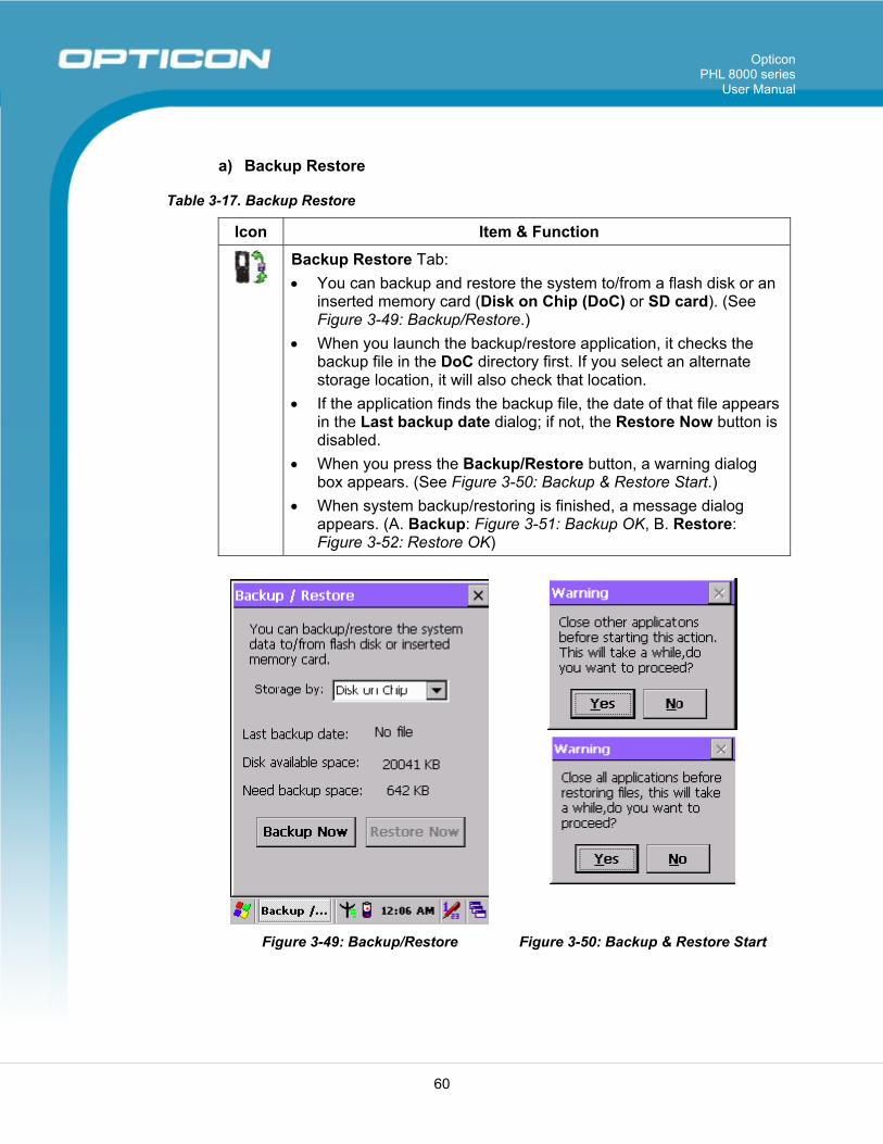
Opticon PHL 8000 series
User Manual
60
a) Backup Restore
Table 3-17. Backup Restore
Icon Item & Function
Backup Restore Tab: • You can backup and restore the system to/from a flash disk or an
inserted memory card (Disk on Chip (DoC) or SD card). (See Figure 3-49: Backup/Restore.)
• When you launch the backup/restore application, it checks the backup file in the DoC directory first. If you select an alternate storage location, it will also check that location.
• If the application finds the backup file, the date of that file appears in the Last backup date dialog; if not, the Restore Now button is disabled.
• When you press the Backup/Restore button, a warning dialog box appears. (See Figure 3-50: Backup & Restore Start.)
• When system backup/restoring is finished, a message dialog appears. (A. Backup: Figure 3-51: Backup OK, B. Restore: Figure 3-52: Restore OK)
Figure 3-49: Backup/Restore Figure 3-50: Backup & Restore Start
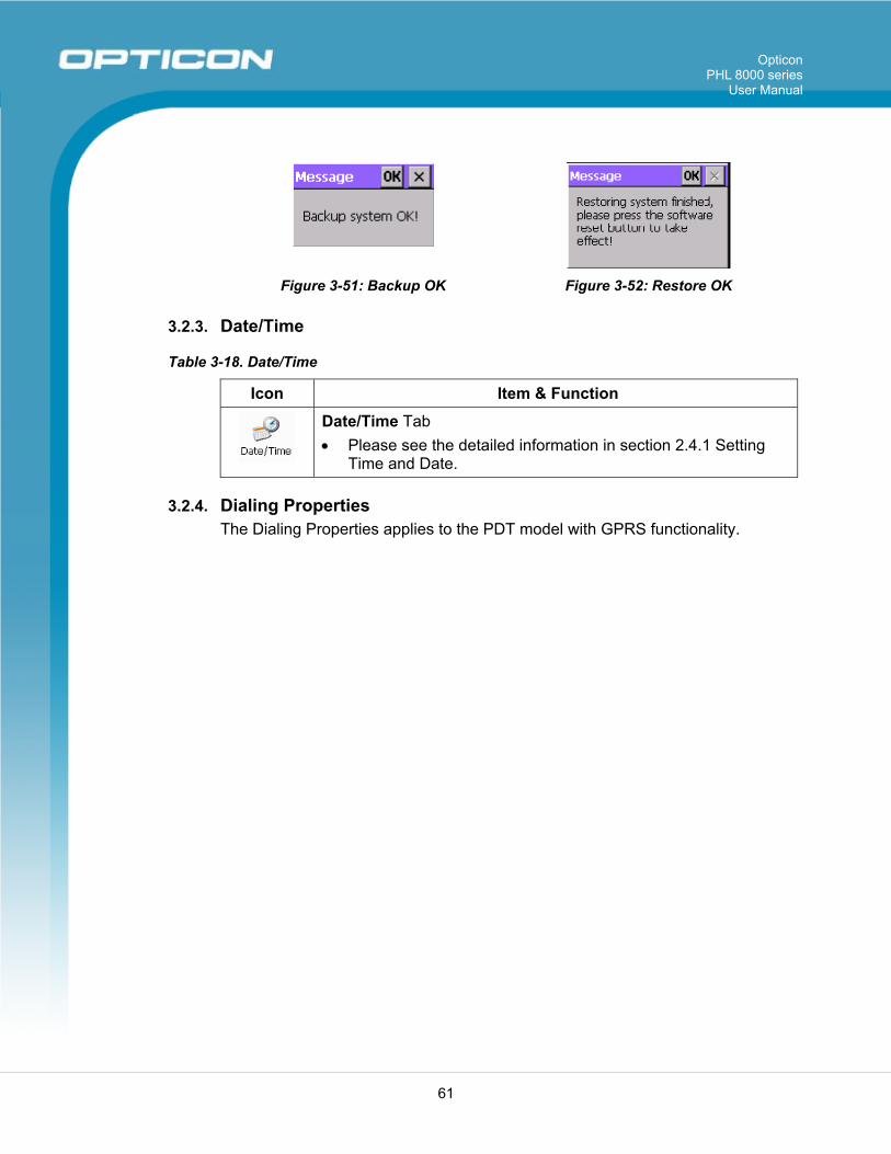
Opticon PHL 8000 series
User Manual
61
Figure 3-51: Backup OK Figure 3-52: Restore OK
3.2.3. Date/Time
Table 3-18. Date/Time
Icon Item & Function
Date/Time Tab • Please see the detailed information in section 2.4.1 Setting
Time and Date.
3.2.4. Dialing Properties The Dialing Properties applies to the PDT model with GPRS functionality.
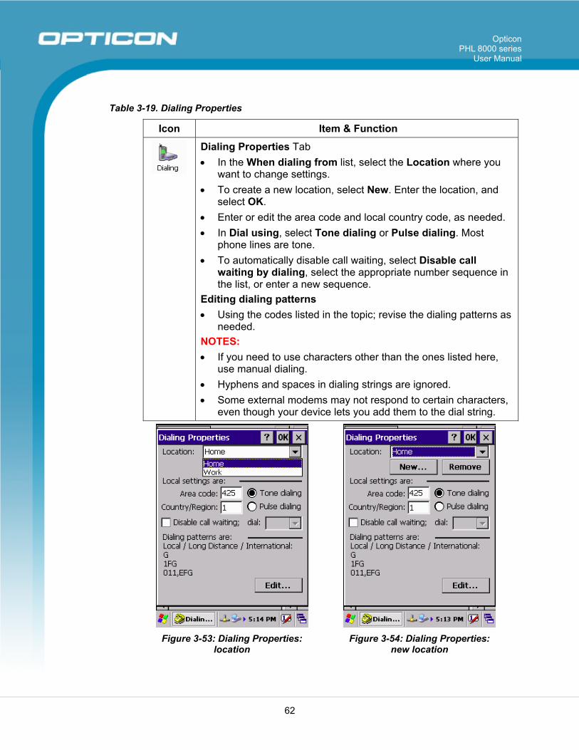
Opticon PHL 8000 series
User Manual
62
Table 3-19. Dialing Properties
Icon Item & Function
Dialing Properties Tab • In the When dialing from list, select the Location where you
want to change settings. • To create a new location, select New. Enter the location, and
select OK. • Enter or edit the area code and local country code, as needed. • In Dial using, select Tone dialing or Pulse dialing. Most
phone lines are tone. • To automatically disable call waiting, select Disable call
waiting by dialing, select the appropriate number sequence in the list, or enter a new sequence.
Editing dialing patterns • Using the codes listed in the topic; revise the dialing patterns as
needed. NOTES: • If you need to use characters other than the ones listed here,
use manual dialing. • Hyphens and spaces in dialing strings are ignored. • Some external modems may not respond to certain characters,
even though your device lets you add them to the dial string.
Figure 3-53: Dialing Properties:
location Figure 3-54: Dialing Properties:
new location
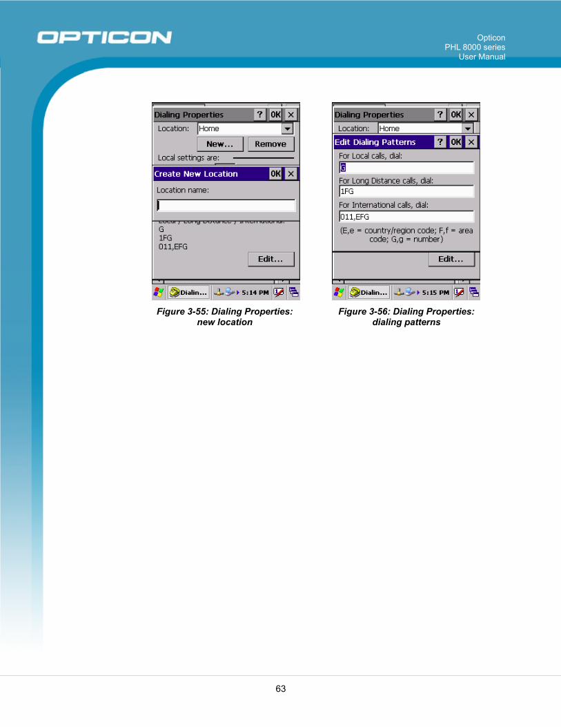
Opticon PHL 8000 series
User Manual
63
Figure 3-55: Dialing Properties:
new location Figure 3-56: Dialing Properties:
dialing patterns
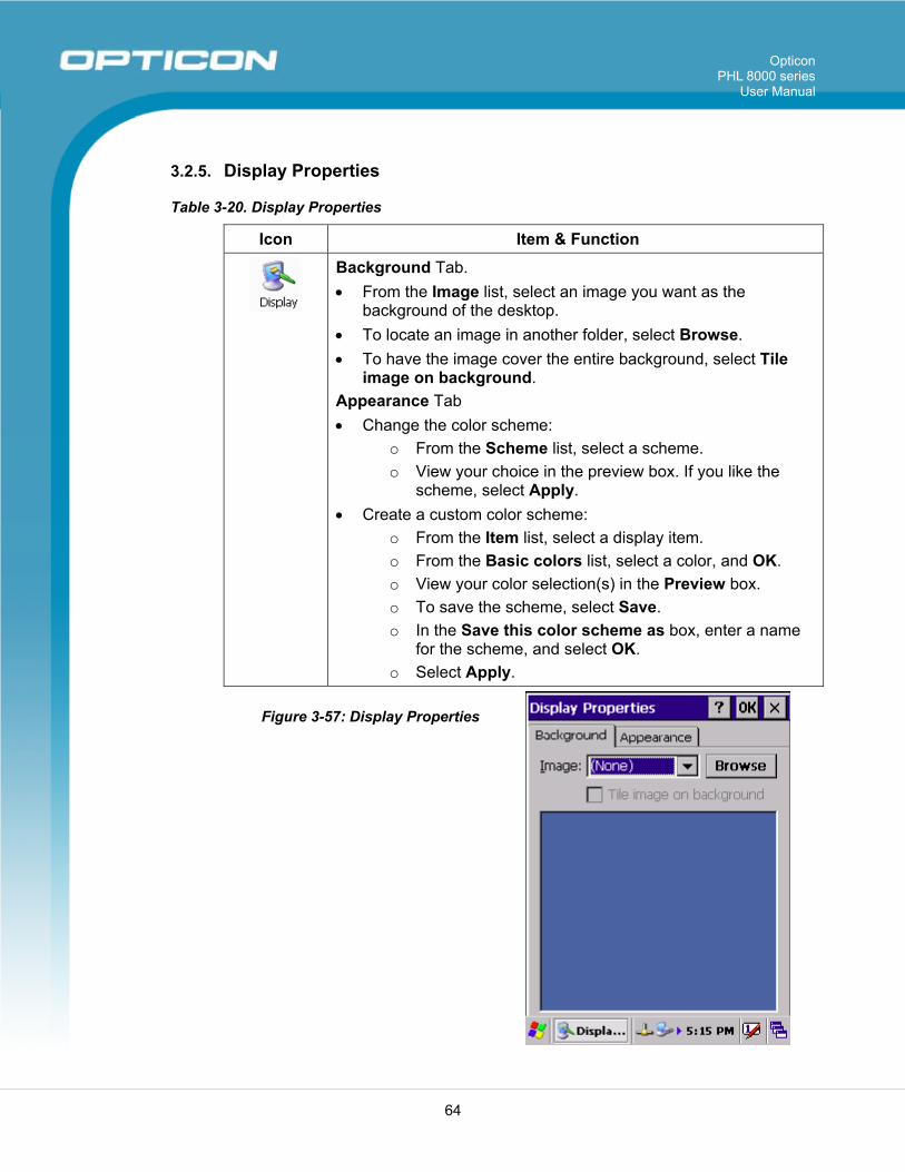
Opticon PHL 8000 series
User Manual
64
3.2.5. Display Properties
Table 3-20. Display Properties
Icon Item & Function
Background Tab. • From the Image list, select an image you want as the
background of the desktop. • To locate an image in another folder, select Browse. • To have the image cover the entire background, select Tile
image on background. Appearance Tab • Change the color scheme:
o From the Scheme list, select a scheme. o View your choice in the preview box. If you like the
scheme, select Apply. • Create a custom color scheme:
o From the Item list, select a display item. o From the Basic colors list, select a color, and OK. o View your color selection(s) in the Preview box. o To save the scheme, select Save. o In the Save this color scheme as box, enter a name
for the scheme, and select OK. o Select Apply.
Figure 3-57: Display Properties
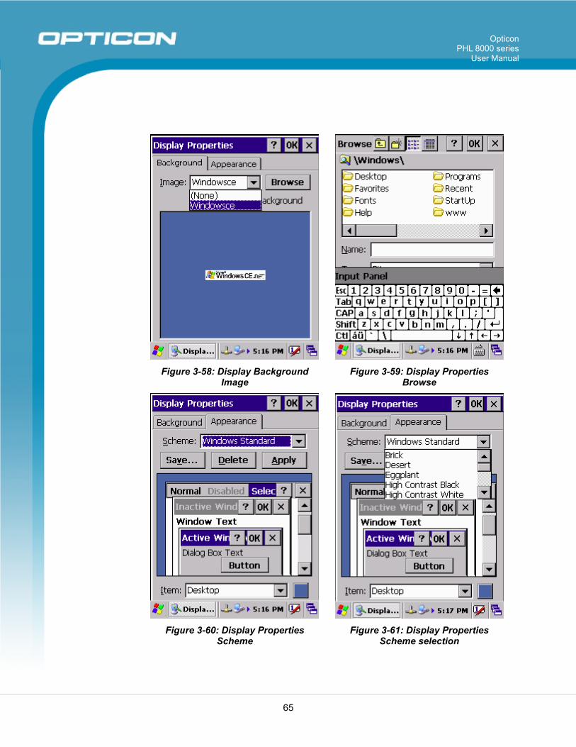
Opticon PHL 8000 series
User Manual
65
Figure 3-58: Display Background
Image Figure 3-59: Display Properties
Browse
Figure 3-60: Display Properties
Scheme Figure 3-61: Display Properties
Scheme selection
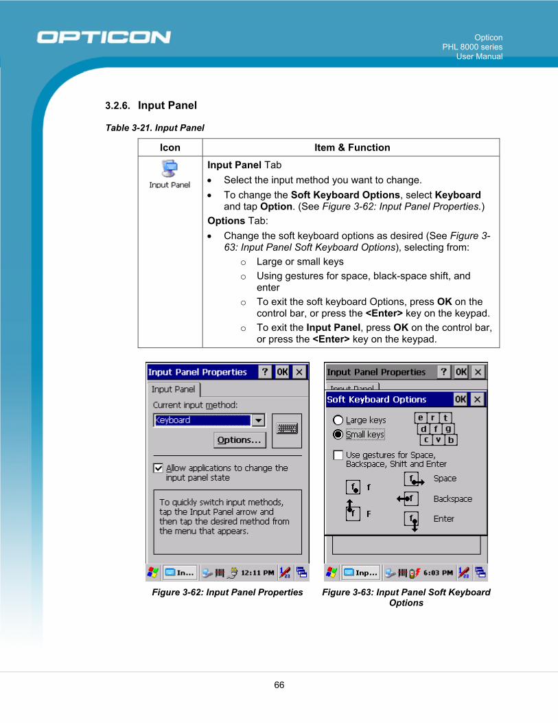
Opticon PHL 8000 series
User Manual
66
3.2.6. Input Panel
Table 3-21. Input Panel
Icon Item & Function
Input Panel Tab • Select the input method you want to change. • To change the Soft Keyboard Options, select Keyboard
and tap Option. (See Figure 3-62: Input Panel Properties.) Options Tab: • Change the soft keyboard options as desired (See Figure 3-
63: Input Panel Soft Keyboard Options), selecting from: o Large or small keys o Using gestures for space, black-space shift, and
enter o To exit the soft keyboard Options, press OK on the
control bar, or press the <Enter> key on the keypad. o To exit the Input Panel, press OK on the control bar,
or press the <Enter> key on the keypad.
Figure 3-62: Input Panel Properties Figure 3-63: Input Panel Soft Keyboard
Options
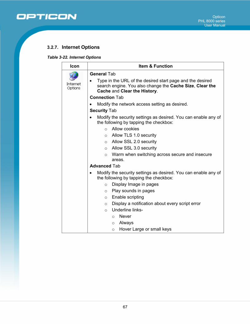
Opticon PHL 8000 series
User Manual
67
3.2.7. Internet Options
Table 3-22. Internet Options
Icon Item & Function
General Tab • Type in the URL of the desired start page and the desired
search engine. You also change the Cache Size, Clear the Cache and Clear the History.
Connection Tab • Modify the network access setting as desired. Security Tab • Modify the security settings as desired. You can enable any of
the following by tapping the checkbox: o Allow cookies o Allow TLS 1.0 security o Allow SSL 2.0 security o Allow SSL 3.0 security o Warm when switching across secure and insecure
areas. Advanced Tab • Modify the security settings as desired. You can enable any of
the following by tapping the checkbox: o Display Image in pages o Play sounds in pages o Enable scripting o Display a notification about every script error o Underline links-
o Never o Always o Hover Large or small keys
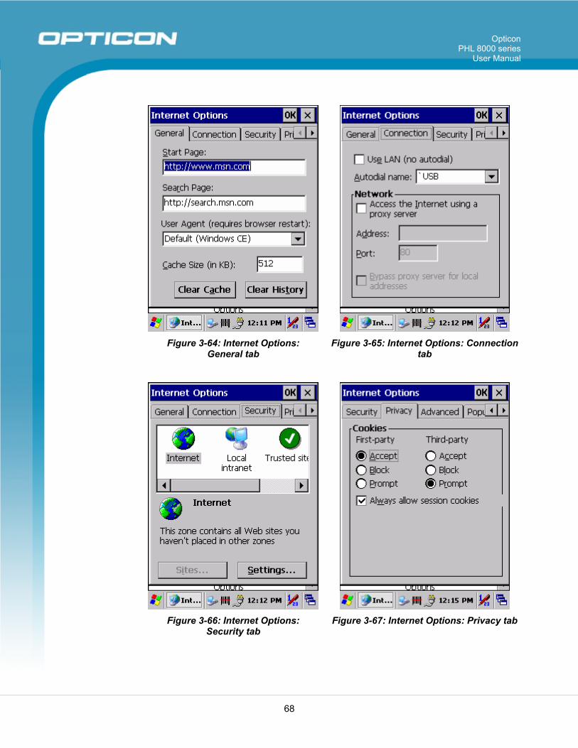
Opticon PHL 8000 series
User Manual
68
Figure 3-64: Internet Options:
General tab Figure 3-65: Internet Options: Connection
tab
Figure 3-66: Internet Options:
Security tab Figure 3-67: Internet Options: Privacy tab
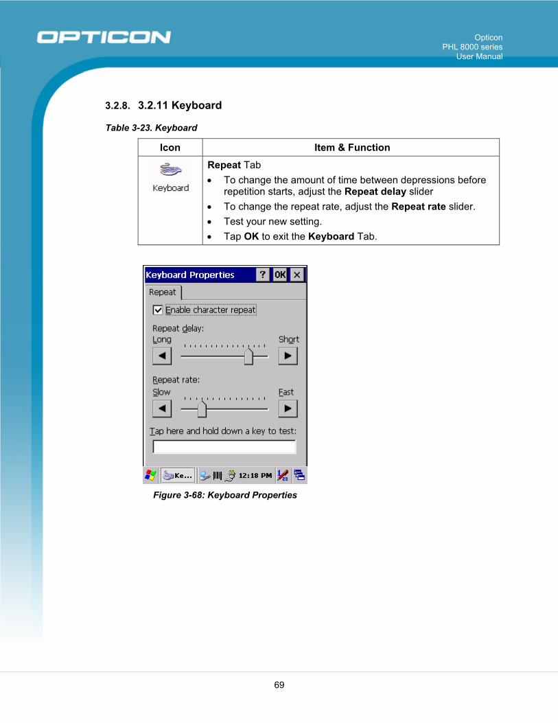
Opticon PHL 8000 series
User Manual
69
3.2.8. 3.2.11 Keyboard
Table 3-23. Keyboard
Icon Item & Function
Repeat Tab • To change the amount of time between depressions before
repetition starts, adjust the Repeat delay slider • To change the repeat rate, adjust the Repeat rate slider. • Test your new setting. • Tap OK to exit the Keyboard Tab.
Figure 3-68: Keyboard Properties
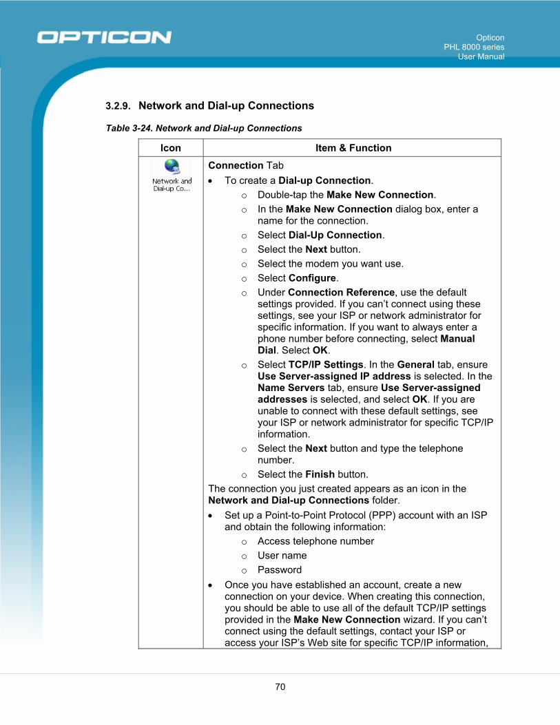
Opticon PHL 8000 series
User Manual
70
3.2.9. Network and Dial-up Connections
Table 3-24. Network and Dial-up Connections
Icon Item & Function
Connection Tab • To create a Dial-up Connection.
o Double-tap the Make New Connection. o In the Make New Connection dialog box, enter a
name for the connection. o Select Dial-Up Connection. o Select the Next button. o Select the modem you want use. o Select Configure. o Under Connection Reference, use the default
settings provided. If you can’t connect using these settings, see your ISP or network administrator for specific information. If you want to always enter a phone number before connecting, select Manual Dial. Select OK.
o Select TCP/IP Settings. In the General tab, ensure Use Server-assigned IP address is selected. In the Name Servers tab, ensure Use Server-assigned addresses is selected, and select OK. If you are unable to connect with these default settings, see your ISP or network administrator for specific TCP/IP information.
o Select the Next button and type the telephone number.
o Select the Finish button. The connection you just created appears as an icon in the Network and Dial-up Connections folder. • Set up a Point-to-Point Protocol (PPP) account with an ISP
and obtain the following information: o Access telephone number o User name o Password
• Once you have established an account, create a new connection on your device. When creating this connection, you should be able to use all of the default TCP/IP settings provided in the Make New Connection wizard. If you can’t connect using the default settings, contact your ISP or access your ISP’s Web site for specific TCP/IP information,
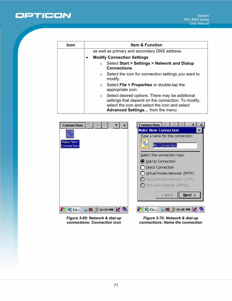
Opticon PHL 8000 series
User Manual
71
Icon Item & Function as well as primary and secondary DNS address.
• Modify Connection Settings o Select Start > Settings > Network and Dialup
Connections o Select the icon for connection settings you want to
modify. o Select File > Properties or double-tap the
appropriate icon. o Select desired options. There may be additional
settings that depend on the connection. To modify, select the icon and select the icon and select Advanced Settings… from the menu.
Figure 3-69: Network & dial-up connections: Connection icon
Figure 3-70: Network & dial-up connections: Name the connection
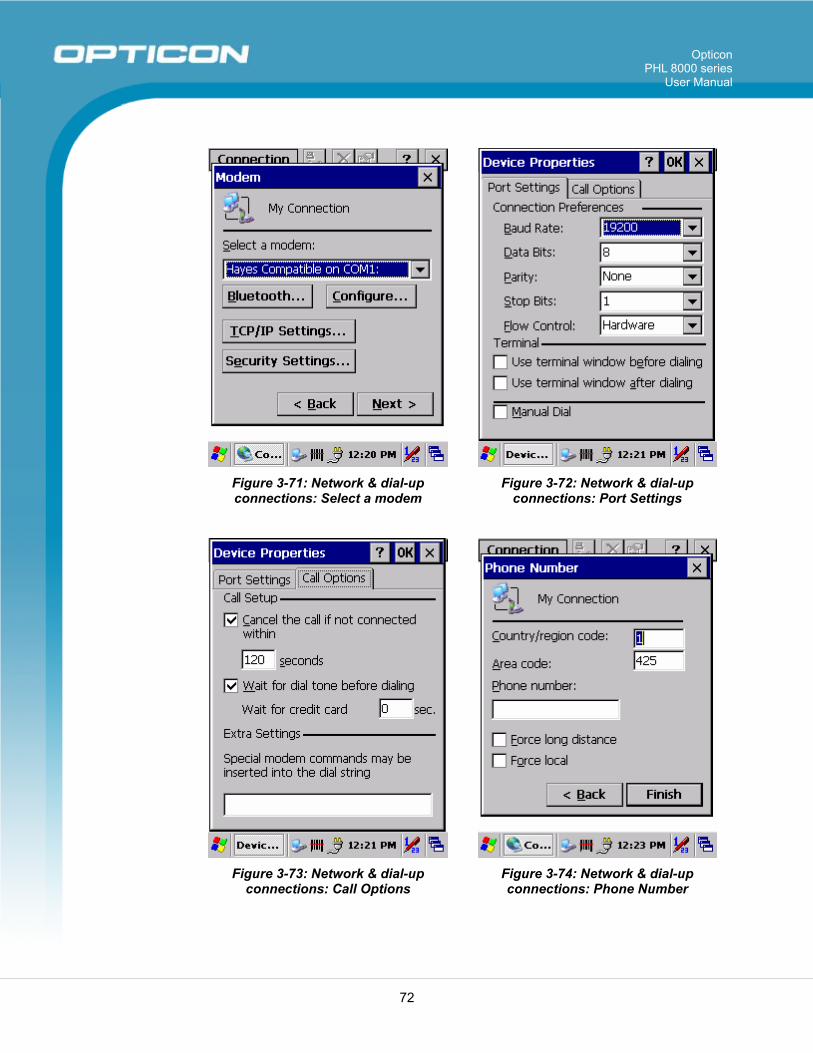
Opticon PHL 8000 series
User Manual
72
Figure 3-71: Network & dial-up connections: Select a modem
Figure 3-72: Network & dial-up connections: Port Settings
Figure 3-73: Network & dial-up
connections: Call Options Figure 3-74: Network & dial-up connections: Phone Number
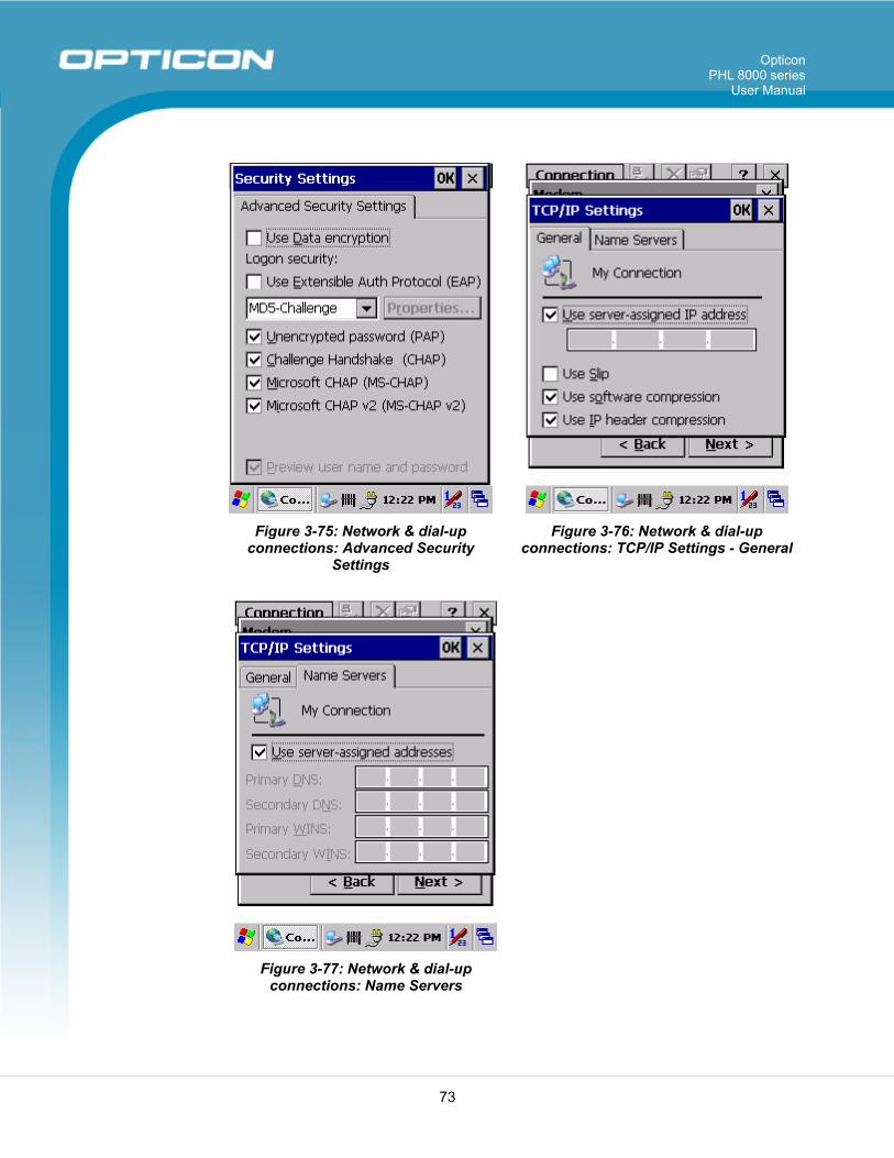
Opticon PHL 8000 series
User Manual
73
Figure 3-75: Network & dial-up
connections: Advanced Security Settings
Figure 3-76: Network & dial-up connections: TCP/IP Settings - General
Figure 3-77: Network & dial-up
connections: Name Servers
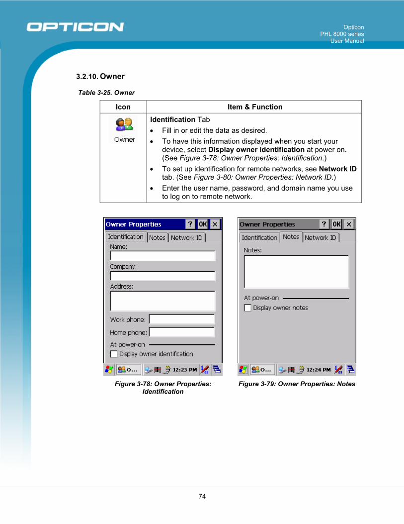
Opticon PHL 8000 series
User Manual
74
3.2.10. Owner
Table 3-25. Owner
Icon Item & Function
Identification Tab • Fill in or edit the data as desired. • To have this information displayed when you start your
device, select Display owner identification at power on. (See Figure 3-78: Owner Properties: Identification.)
• To set up identification for remote networks, see Network ID tab. (See Figure 3-80: Owner Properties: Network ID.)
• Enter the user name, password, and domain name you use to log on to remote network.
Figure 3-78: Owner Properties:
Identification Figure 3-79: Owner Properties: Notes
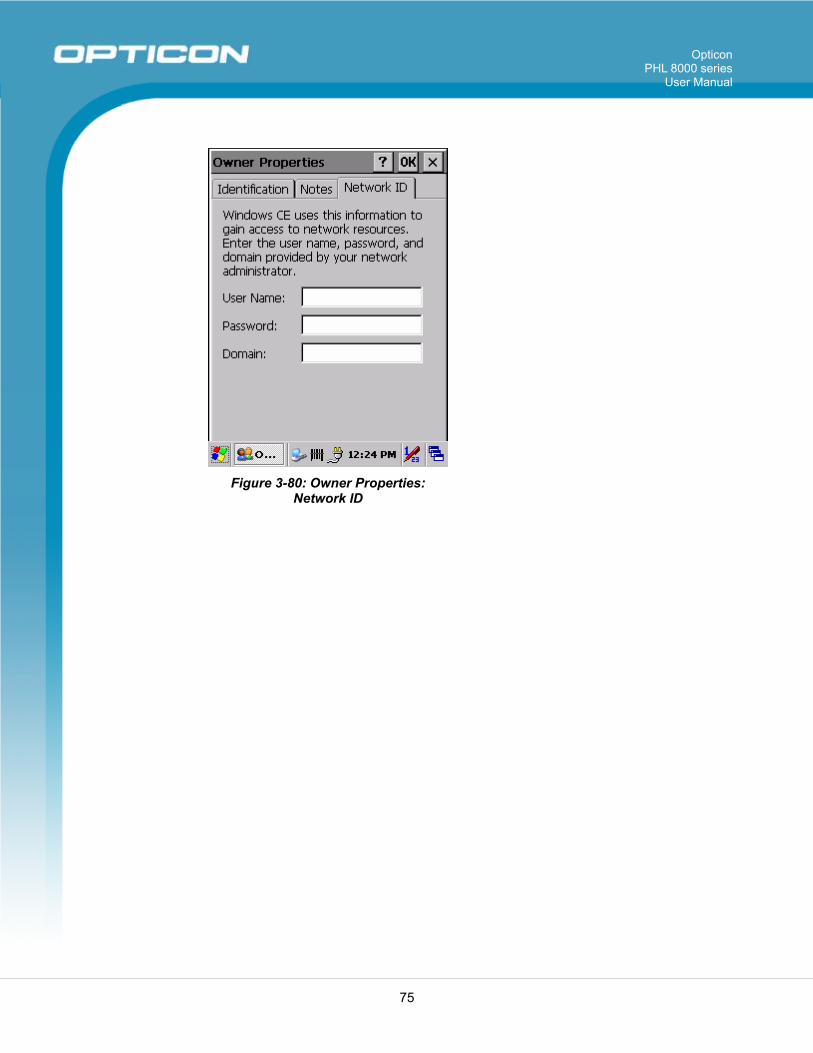
Opticon PHL 8000 series
User Manual
75
Figure 3-80: Owner Properties: Network ID
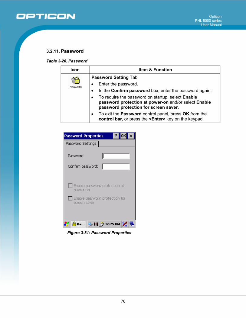
Opticon PHL 8000 series
User Manual
76
3.2.11. Password
Table 3-26. Password
Icon Item & Function
Password Setting Tab • Enter the password. • In the Confirm password box, enter the password again. • To require the password on startup, select Enable
password protection at power-on and/or select Enable password protection for screen saver.
• To exit the Password control panel, press OK from the control bar, or press the <Enter> key on the keypad.
Figure 3-81: Password Properties
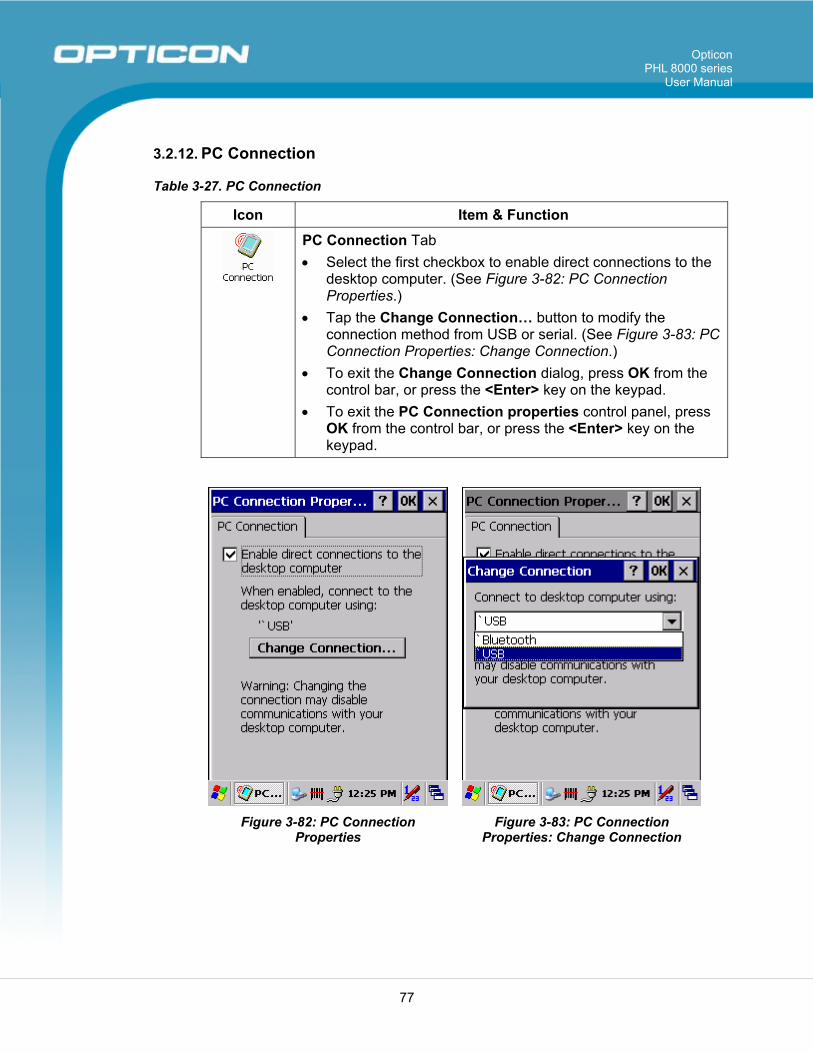
Opticon PHL 8000 series
User Manual
77
3.2.12. PC Connection
Table 3-27. PC Connection
Icon Item & Function
PC Connection Tab • Select the first checkbox to enable direct connections to the
desktop computer. (See Figure 3-82: PC Connection Properties.)
• Tap the Change Connection… button to modify the connection method from USB or serial. (See Figure 3-83: PC Connection Properties: Change Connection.)
• To exit the Change Connection dialog, press OK from the control bar, or press the <Enter> key on the keypad.
• To exit the PC Connection properties control panel, press OK from the control bar, or press the <Enter> key on the keypad.
Figure 3-82: PC Connection Properties
Figure 3-83: PC Connection Properties: Change Connection
Opticon PHL 8000 series
User Manual
78
3.2.13. Power
Table 3-28. Power Properties
Icon Item & Function
Battery Tab • Provide change level indicators for Main battery and
Backup battery. • Provide remaining power capacity of main battery. • If a Main Batteries Very Low warning message shows, the
remaining battery life is about 30 minutes before the PHL 8100 shuts down. (See Figure 3-84: Power Properties: Battery.)
• To exit the Battery control panel, tap OK from the command bar, or tap the <Enter> key on the keypad.
Schemes Tab • The Schemes Tab allows you to determine the time to
Switch state to Suspend mode when using either Battery Power or AC Power.
• Select Battery Power or AC Power as the power scheme from the pull-down list.
• Select the time to suspend mode from the pull-down list. (See Figure 3-86: Power Properties: Switch state to Suspend.)
Device Status Tab • Provide power level of device—The power level ranges from
High (D0), which means the device is at the highest power level, to Off (D4), which means the device is at the lowest power level.
NOTES:
• This icon inside the Task bar shows that the AC adapter is providing power to the PDT.
• This icon inside the Task bar shows that Main Batteries are providing the power to the PDT.
• This icon inside the Task bar shows that the AC adapter is providing the power to the PDT and is charging the main batteries.
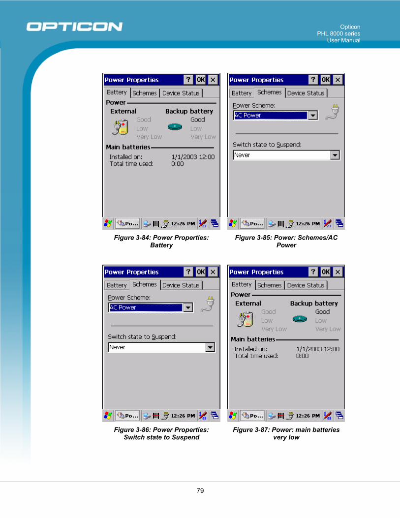
Opticon PHL 8000 series
User Manual
79
Figure 3-84: Power Properties: Battery
Figure 3-85: Power: Schemes/AC Power
Figure 3-86: Power Properties: Switch state to Suspend
Figure 3-87: Power: main batteries very low
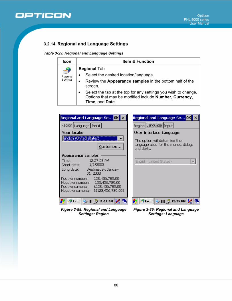
Opticon PHL 8000 series
User Manual
80
3.2.14. Regional and Language Settings
Table 3-29. Regional and Language Settings
Icon Item & Function
Regional Tab • Select the desired location/language. • Review the Appearance samples in the bottom half of the
screen. • Select the tab at the top for any settings you wish to change.
Options that may be modified include Number, Currency, Time, and Date.
Figure 3-88: Regional and Language Settings: Region
Figure 3-89: Regional and Language Settings: Language
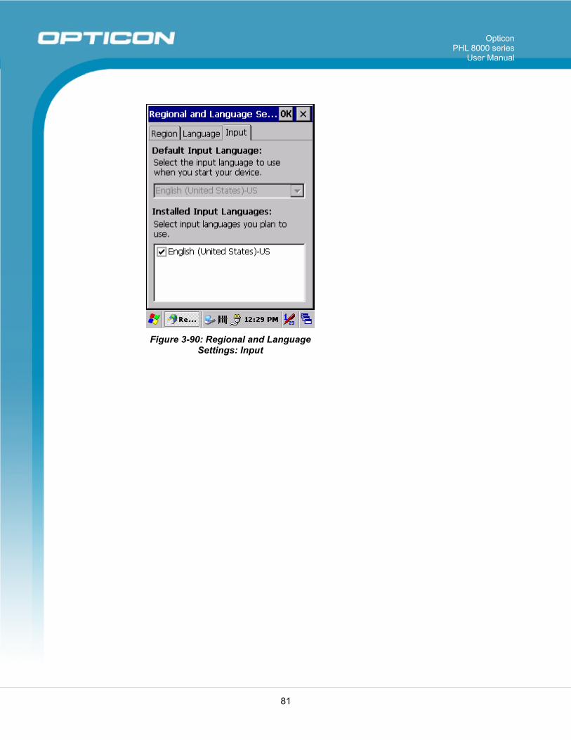
Opticon PHL 8000 series
User Manual
81
Figure 3-90: Regional and Language Settings: Input
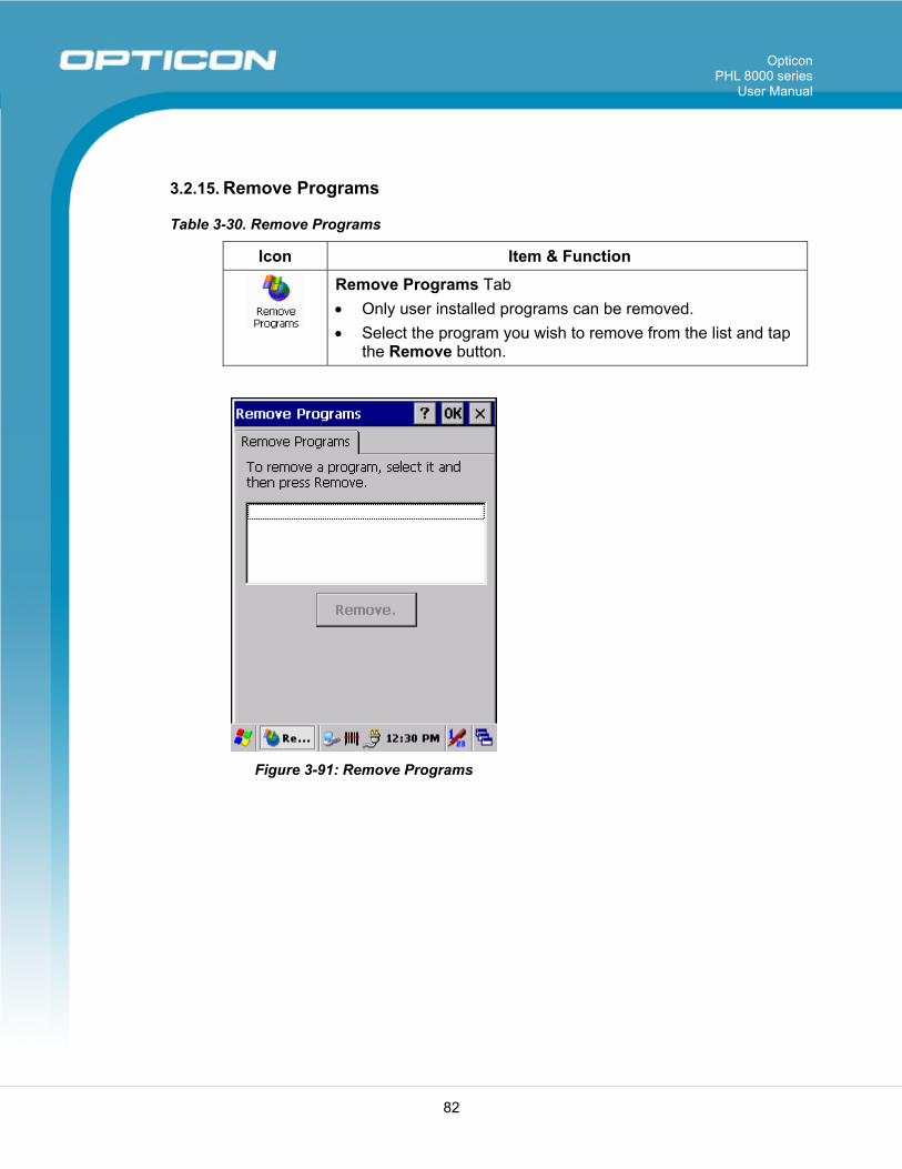
Opticon PHL 8000 series
User Manual
82
3.2.15. Remove Programs
Table 3-30. Remove Programs
Icon Item & Function
Remove Programs Tab • Only user installed programs can be removed. • Select the program you wish to remove from the list and tap
the Remove button.
Figure 3-91: Remove Programs
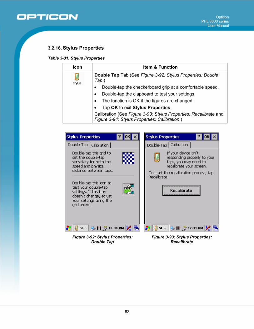
Opticon PHL 8000 series
User Manual
83
3.2.16. Stylus Properties
Table 3-31. Stylus Properties
Icon Item & Function
Double Tap Tab (See Figure 3-92: Stylus Properties: Double Tap.) • Double-tap the checkerboard grip at a comfortable speed. • Double-tap the clapboard to test your settings • The function is OK if the figures are changed. • Tap OK to exit Stylus Properties. Calibration (See Figure 3-93: Stylus Properties: Recalibrate and Figure 3-94: Stylus Properties: Calibration.)
Figure 3-92: Stylus Properties: Double Tap
Figure 3-93: Stylus Properties: Recalibrate
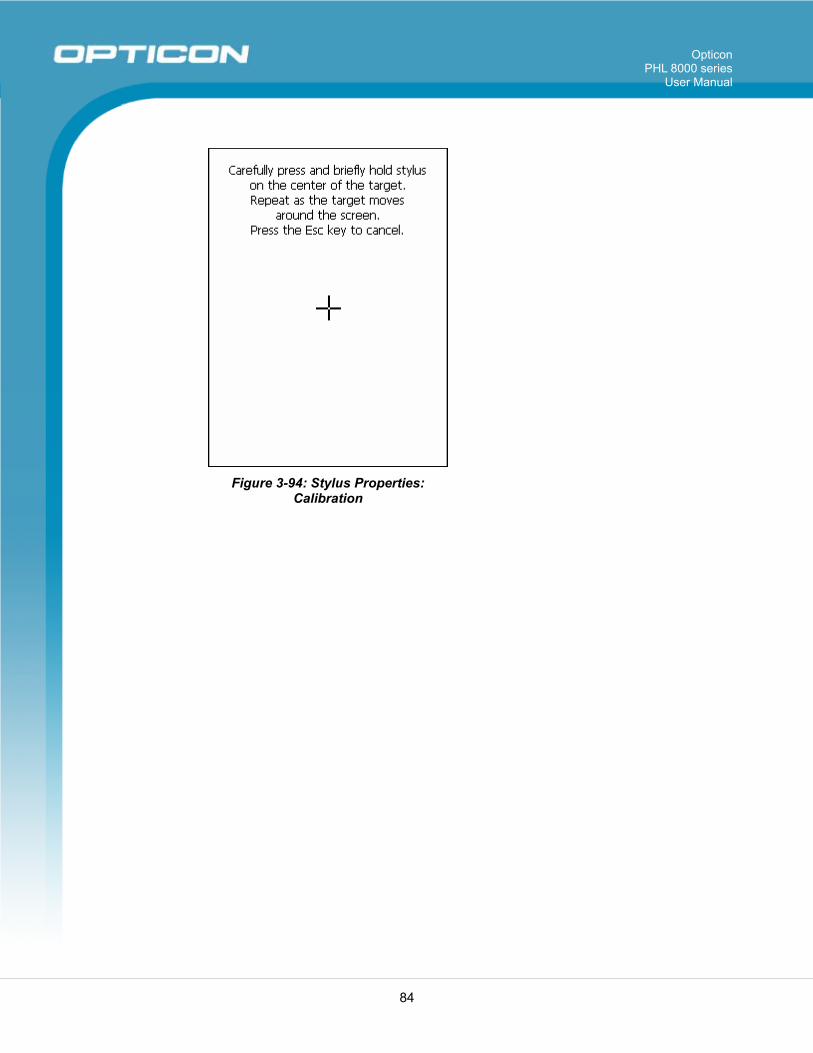
Opticon PHL 8000 series
User Manual
84
Figure 3-94: Stylus Properties: Calibration
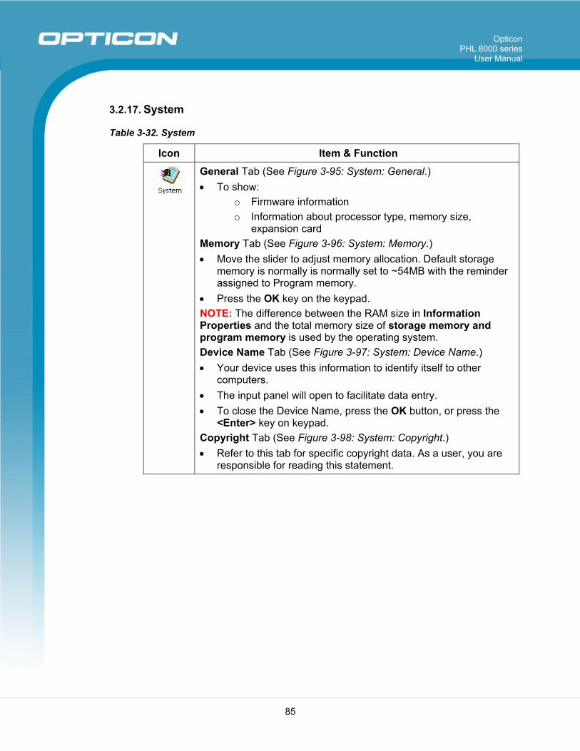
Opticon PHL 8000 series
User Manual
85
3.2.17. System
Table 3-32. System
Icon Item & Function
General Tab (See Figure 3-95: System: General.) • To show:
o Firmware information o Information about processor type, memory size,
expansion card Memory Tab (See Figure 3-96: System: Memory.) • Move the slider to adjust memory allocation. Default storage
memory is normally is normally set to ~54MB with the reminder assigned to Program memory.
• Press the OK key on the keypad. NOTE: The difference between the RAM size in Information Properties and the total memory size of storage memory and program memory is used by the operating system. Device Name Tab (See Figure 3-97: System: Device Name.) • Your device uses this information to identify itself to other
computers. • The input panel will open to facilitate data entry. • To close the Device Name, press the OK button, or press the
<Enter> key on keypad. Copyright Tab (See Figure 3-98: System: Copyright.) • Refer to this tab for specific copyright data. As a user, you are
responsible for reading this statement.
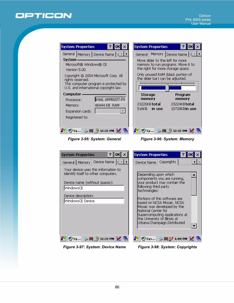
Opticon PHL 8000 series
User Manual
86
Figure 3-95: System: General Figure 3-96: System: Memory
Figure 3-97: System: Device Name Figure 3-98: System: Copyrights
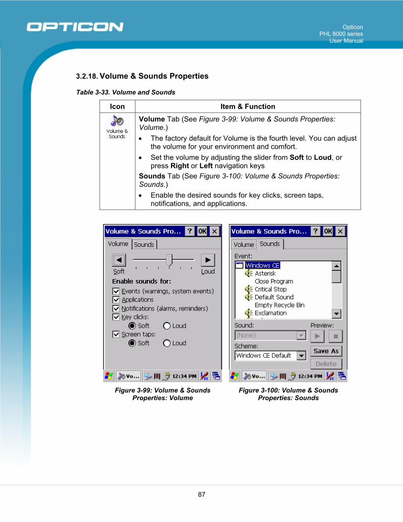
Opticon PHL 8000 series
User Manual
87
3.2.18. Volume & Sounds Properties
Table 3-33. Volume and Sounds
Icon Item & Function
Volume Tab (See Figure 3-99: Volume & Sounds Properties: Volume.) • The factory default for Volume is the fourth level. You can adjust
the volume for your environment and comfort. • Set the volume by adjusting the slider from Soft to Loud, or
press Right or Left navigation keys Sounds Tab (See Figure 3-100: Volume & Sounds Properties: Sounds.) • Enable the desired sounds for key clicks, screen taps,
notifications, and applications.
Figure 3-99: Volume & Sounds Properties: Volume
Figure 3-100: Volume & Sounds Properties: Sounds
Opticon PHL 8000 series
User Manual
88
3.3. Task Bar and Start Menu
Table 3-34. Task Bar and Start Menu
Icon Item & Function
Task Bar and Start
Menu
General Tab • In this tab, you can change the position of the Task bar and
Start menu • Is Always on top or not • Auto hide or not • Show clock or not Advanced Tab: • Tap the Clear button to remove the contents of the
documents menu. • Enable Expand Control Panel to list all icons of Control
Panel from top to bottom.
Opticon PHL 8000 series
User Manual
89
4. Communication 4.1. Installing & Setting Up Microsoft ActiveSync
4.1.1. Installing Microsoft ActiveSync on the Host PC Microsoft ActiveSync is a file transfer tool to synchronize the files on a PC with the files on your PDT. To install Microsoft ActiveSync, complete the following steps on the PC: 4. Go to the Microsoft Windows CE.NET Web site and download the current
version of ActiveSync: http://www.microsoft.com/mobile/pockeypc/downloads/.
5. Install the latest version of Microsoft ActiveSync on the host PC.
6. Open ActiveSync.
7. Select File > Communication Settings from the ActiveSync menu bar.
8. Go to Using ActiveSync in section 4.2 to continue using ActiveSync.
4.1.2. Connecting PDT to Host PC 1. You can use either the USB/serial (RS-232C) port of Single Dock or a
USB/serial (RS-232C) cable to connect the PDT to the host PC.
• To use the dock, you must first insert the PDT into the slot, making sure that the unit is firmly seated the dock.
• To use the cable, connect the USB/serial cable to the PDT.
2. Connect the USB/serial dock or cable to the host PC’s serial port or USB port.
3. Connect to the host PC via Bluetooth, or IrDA ActiveSync.
4. Connect the dock or PDT to the power adapter and power source.
4.2. Using ActiveSync Use ActiveSync to transfer and synchronize files between the PDT and the host PC.
4.2.1. Setting up a Partnership During the Microsoft ActiveSync installation, you were prompted to create a partnership with your mobile device. When you set up a partnership, you select synchronization and file conversation settings, which are contained in a file on your desktop computer. This file enables your desktop computer to recognize your device. Only devices that have a partnership with a desktop computer can synchronize information between the two computers. For more information on partnerships, please refer to your Microsoft ActiveSync documentation or help file.
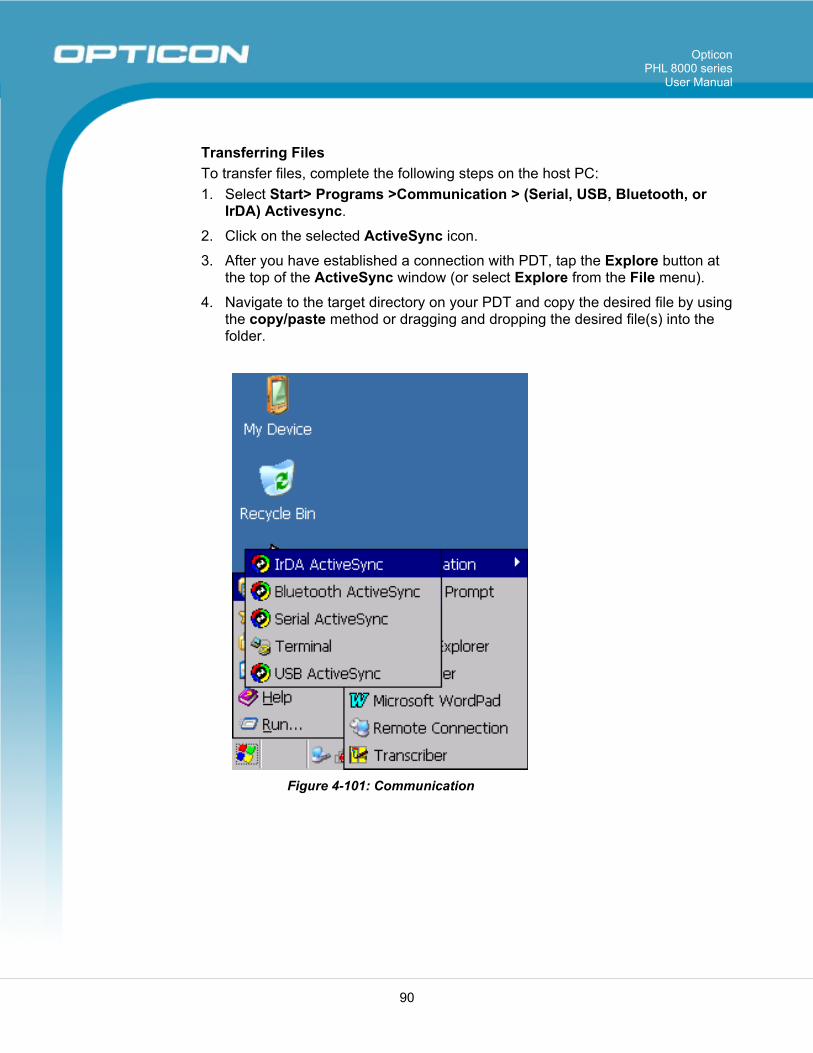
Opticon PHL 8000 series
User Manual
90
Transferring Files To transfer files, complete the following steps on the host PC: 1. Select Start> Programs >Communication > (Serial, USB, Bluetooth, or
IrDA) Activesync.
2. Click on the selected ActiveSync icon.
3. After you have established a connection with PDT, tap the Explore button at the top of the ActiveSync window (or select Explore from the File menu).
4. Navigate to the target directory on your PDT and copy the desired file by using the copy/paste method or dragging and dropping the desired file(s) into the folder.
Figure 4-101: Communication
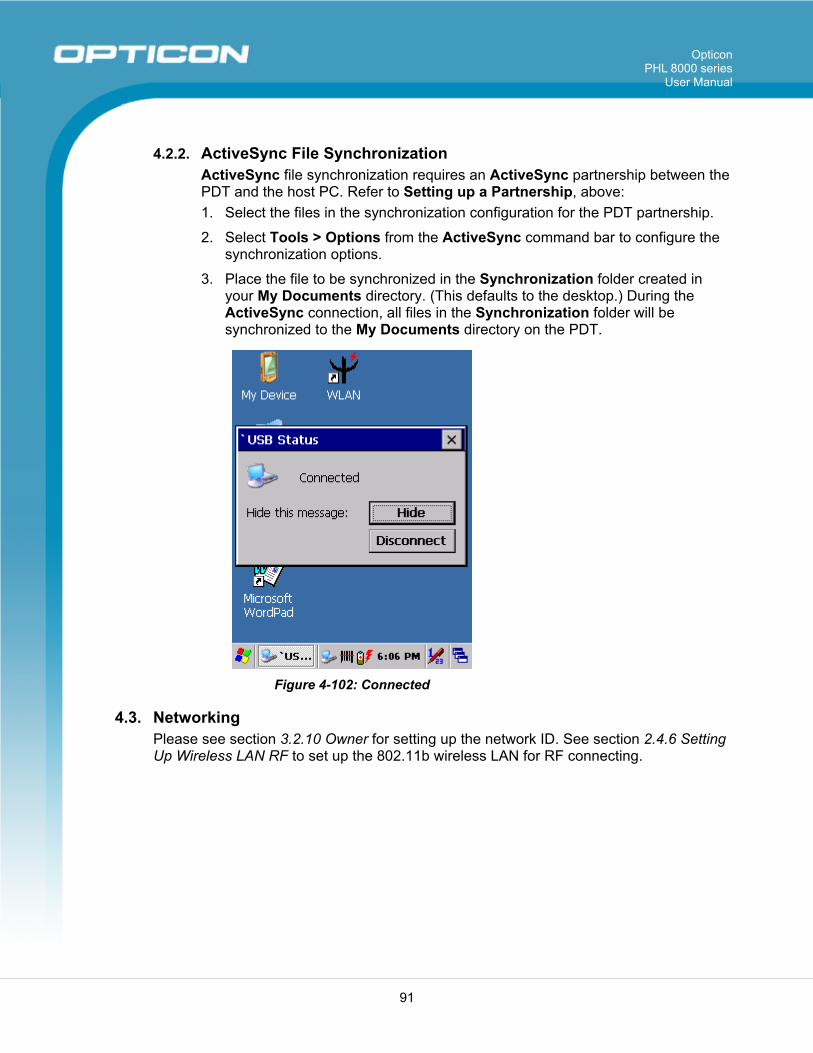
Opticon PHL 8000 series
User Manual
91
4.2.2. ActiveSync File Synchronization ActiveSync file synchronization requires an ActiveSync partnership between the PDT and the host PC. Refer to Setting up a Partnership, above: 1. Select the files in the synchronization configuration for the PDT partnership.
2. Select Tools > Options from the ActiveSync command bar to configure the synchronization options.
3. Place the file to be synchronized in the Synchronization folder created in your My Documents directory. (This defaults to the desktop.) During the ActiveSync connection, all files in the Synchronization folder will be synchronized to the My Documents directory on the PDT.
Figure 4-102: Connected
4.3. Networking Please see section 3.2.10 Owner for setting up the network ID. See section 2.4.6 Setting Up Wireless LAN RF to set up the 802.11b wireless LAN for RF connecting.
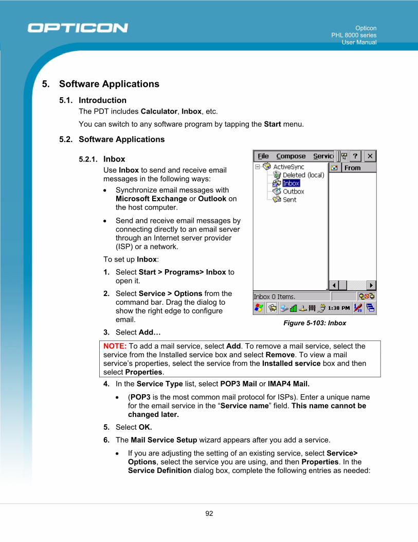
Opticon PHL 8000 series
User Manual
92
5. Software Applications 5.1. Introduction
The PDT includes Calculator, Inbox, etc.
You can switch to any software program by tapping the Start menu.
5.2. Software Applications
5.2.1. Inbox Use Inbox to send and receive email messages in the following ways: • Synchronize email messages with
Microsoft Exchange or Outlook on the host computer.
• Send and receive email messages by connecting directly to an email server through an Internet server provider (ISP) or a network.
To set up Inbox:
1. Select Start > Programs> Inbox to open it.
2. Select Service > Options from the command bar. Drag the dialog to show the right edge to configure email.
3. Select Add…
NOTE: To add a mail service, select Add. To remove a mail service, select the service from the Installed service box and select Remove. To view a mail service’s properties, select the service from the Installed service box and then select Properties. 4. In the Service Type list, select POP3 Mail or IMAP4 Mail.
• (POP3 is the most common mail protocol for ISPs). Enter a unique name for the email service in the “Service name” field. This name cannot be changed later.
5. Select OK. 6. The Mail Service Setup wizard appears after you add a service.
• If you are adjusting the setting of an existing service, select Service> Options, select the service you are using, and then Properties. In the Service Definition dialog box, complete the following entries as needed:
Figure 5-103: Inbox
Opticon PHL 8000 series
User Manual
93
Connection: Select the name of the connection you created to connect to the mail server. If you are receiving email through a network (Ethernet) connection, select Network Connection. If you want Inbox to use your current connection, select (none). If you have not created a connection, select Create new connection. Double-tap the Make New Connection icon, and follow the instructions in the wizard. When finished, select Inbox in the Task bar and continue setting up Inbox.
POP3 Host (POP3 only): Enter the name of the mail server you use to receive and send messages.
Server (IMPA4 only): Enter the name of he mail server you use to receive and send messages.
User ID: Enter the user name or mailbox ID assigned to you. Password: Enter the password you use to access this mail account. If
you do not want to be prompted to enter the password each time you connect, select Save password.
Domain (Windows NT): Enter your Windows NT domain name. This name is required only when connecting to networks, such as a corporate network, that use Windows NT domain security. This is not required for most ISP accounts. If you have trouble connecting, try clearing this box.
SMTP Host: If your mail service uses a separate server for SMTP, enter the name in the box. If you’re setting up a POP3 Mail service with an ISP, the ISP must use an SMTP mail gateway.
Return Address: By default, the return address is set to username@POP3host or username@Servername, depending on the service you are using. If this is not your email address, enter the correct address in the box.
7. Set general preferences:
• If you are adjusting the setting of an existing service, select Service> Options, select the service you are using, select Properties, and then select Next. In the General Preferences dialog box, choose any of the following settings, all of which are optional:
Disconnect service after actions are performed: Select to automatically disconnect from the server upon completion of all pending actions. This option minimizes connect time and cost.
Check for new messages every: Select the time interval (in minutes) at which you want the device to check for new mail. If this option is turned off, you must check for new mail manually by selecting Services> Send/Receive Mail.
Display a message box when new mail arrives (POP3 only): Select to be informed that new mail has arrived.
Display a message box when new mail arrives (IMAP4 only): Select to be informed that new mail has arrived.
Opticon PHL 8000 series
User Manual
94
Send using MIME format (POP3 only): Select to send messages with extended characters.
Only display messages from last 3 days: Select how many days’ messages you want downloaded.
8. Set Inbox Preferences:
• If you are adjusting the settings of an existing service, select Services > Options, select the service you are using, select Properties, and then select New twice. In the Inbox Preferences dialog box, choose any of the following options:
Get message headers only: Select to save storage space and time by downloading only headers. You can download a full copy of the message later by selecting the message and then Services> Get Full Copy.
Include <number> lines: Select to set the message length (approximate number of lines) that you want to download.
Get Full Copy of Messages: Select to receive a full copy of all messages. In addition to the message body, any options you select in When getting full copy will be downloaded. Selecting this option increases the amount of time needed to download messages.
Only synchronize folder hierarchy under Inbox (IMAP4 only): Select to speed download time by preventing the complete downloaded of the folder list every time you connect.
Get meeting requests (POP3 only): Select to download and store copies of meeting requests when getting full copies of messages. This setting applies whether you have chosen to download full copies of messages by default, or you selectively download full copies of messages by opening the message and selecting Services> Get Full Copy. Limitations apply.
Get file attachments (POP3 only): Select to download and save message attachments when getting full copies of messages. This option may use significant RAM and slow download time. This setting applies whether you have chosen to download full copies of messages by default, or if you selectively download full copies of messages and selecting Services> Get Full Copy.
Get file attachments and meeting requests (IMAP4 only): Select to download and store meeting requests and message attachments when getting full copies of messages. This setting applies you have chosen to download full copies of messages by default, or if you selectively download full copies of messages by opening the message and selecting Services> Get Full Copy. Limitations apply.
Only if smaller than (IMAP4 only): Select to restrict the size of the attachments you download. Set to 10K if you want to receive meeting requests only.
9. Include the original message in a reply:
Opticon PHL 8000 series
User Manual
95
• Select Services > Options> Compose tab.
• Under Reply, select Include Body. This setting will place a copy of the original message beneath your response text.
• To indent the original message, select Indent.
• To add leading characters (such as >) to the original message lines, select Add leading character, and enter the character you want.
10. Save copies of sent messages:
• By default, sent messages are not saved on your device.
• Select Services > Options> Compose tab.
• Select Keep copy of sent mail in Sent folder. 11. Set the action to follow deleting, moving, or responding to a message:
• Select Services > Options > Read tab.
• Select desired options.
12. Delete a message:
• Select the message and select File > Delete. Messages are moved to the Deleted (local) folder and deleted according to the option you have selected in the Services > Options > Delete tab:
• On connect/disconnect: Deletes messages when you connect or disconnect from your mail service or exit Inbox.
• Immediately: Deletes messages as soon as you select File > Delete.
• Manual: Deletes messages when you select File > Empty Deleted (local).
NOTE: If you are working offline, messages that have been deleted from the device will be deleted from the server the next time you connect.
13. Empty the Deleted (local) Folder:
• Select File > Empty Deleted (local). This permanently deletes messages in the Deleted (local) folder.
• To check or adjust the current settings for deleting messages, select Services > Options> Delete tab.
14. Move or copy a message:
CAUTION: When you move a message that you have received through POP3 or synchronization to a folder you created on your device, the copy of the message on the server is deleted. This prevents duplicate copies of messages. Although the complete message is moved, message attachments will be deleted if you have not selected the option to download attachments. Once the message is moved, you will be able to access the message only from your device.
Opticon PHL 8000 series
User Manual
96
• Select the message.
• Select File > Move To or File > Copy To.
• Select the destination folder. If you are working offline, the message will be moved or copied from the server the next time you connect.
15. Folder
• Create a folder: Select File > Folder> New Folder. Type a name for the folder.
• Delete a folder: Select the folder you want to delete. Select File > Delete.
• Designate a folder as offline: Only IMAP4 folders can be designated as offline. All IMAP4 default
folders, such as Inbox, are automatically designated as offline. Messages in offline folders can be viewed when you are disconnected from your mail server. If a folder is not designated as offline, you will be able to read and respond to messages in that folder only when connected to the server.
To designate a folder as offline, select the folder and then select Service > Offline Folder.
• Rename a folder: Select the folder you want to rename. Select File> Folder> Rename Folder. Type the new name for the folder.
NOTES:
• Default folders, such as Inbox, can’t be renamed.
• Folders you create for IMAP4 mail servers can’t be renamed.
• Synchronize folders while connected: When you synchronize folders, the contents of your device folders and mail server folders are compared and uPDTted. New mail messages are downloaded, and messages in your device Outbox folder are sent. The synchronization behavior depends on how you connect to your mail server.
When you connect to a POP3 server, the Inbox and Outbox folders on your device are synchronized with the corresponding folders on the mail server. To synchronize after the initial connection, select Services > Send/Receive Mail.
When you connect to an IMAP4 server, Inbox, Outbox, and all folders marked as offline are synchronized. To synchronize all folders after the initial connection, select Services > Synchronize Folders. To
Opticon PHL 8000 series
User Manual
97
synchronize just the selected folder and the Outbox folder, select Services > Send/Receive Mail.
16. Compose and send a message:
• In list view, select Compose > New Message.
• Enter the address of one or more recipients, separating them with a semicolon. If the recipient is listed in the Address Book, enter a few letters of the recipient’s name and select Compose > Check Name. If there is only one match, the email address is inserted. If there is more than one match, select the correct address from the Choose Email Recipients dialog box. If there is no match, then add a new email address through Choose Email Recipients.
• To attach a file, select File > Attachments > Add Attachment.
• Select File > Send. If you are working offline, the message is moved to the Outbox folder and will be sent the next time you connect.
TIP: To see more header information, select the triangle in the lower-right corner of the header area. Select the triangle again to collapse the header area.
17. Save a message:
• Select File > Save to save the message you are composing or editing. The message is not sent and is saved in the inbox folder of the active service.
18. Reply to or forward a message:
• Open the message, and then select Compose > Reply to Sender, Reply to All, or Forward.
• Enter your response.
• Select File > Send.
TIPS: Selections in the Options dialog box determine whether the original text is included.
To see more header information, select the inverted triangle in the lower-right corner of the header area. Select the triangle again to collapse the header area.
19. Check Inbox status:
• In list view, select Compose > Status. You can view details such as the number of messages to be sent, deleted, and copied, and the number of attachments to be downloaded.
20. Download message from the server:
Opticon PHL 8000 series
User Manual
98
• When you download messages, you need to create two connections: a remote connection and a mail server connection. The remote connection connects you and your ISP or network. The mail server connection downloads messages from your mail server to Inbox on your device. When you select Services > Connect in Inbox, Inbox starts a remote connection using the connection you specified when setting up the current mail service. If you are already connected through a remote connection other than the one you specified in the service, you will be asked if you want to use the current connection. If you choose not to, you will need to disconnect from the current connection before you can check for new messages.
Select the Services menu and make sure that the service you want to use is selected. (The selected service has a bullet next to it.)
Select Services > Connect. The messages on your device and mail server are synchronized: new messages are downloaded to the device Inbox folder, messages in the device Outbox folder are sent, and messages that have been deleted on the server are removed from the device Inbox. Double-tap a message list to open it.
If you read a message and decide that you need the full copy, select File > Get Full Copy while in the message window or Services > Get Full Copy while in list view. This will also download message attachments and meeting requests if you have those options selected in the Inbox Preferences dialog box. You can also choose to download full copies of messages by default.
When finished, select Services > Connect to disconnect. You also need to disconnect your dial-up connection by double-tapping the icon in the status bar and selecting Disconnect.
NOTES:
• Receiving entire messages consumes storage memory.
• The size column in the Inbox list view displays the local size and server size of a message. Even when a message has been downloaded fully, these numbers may differ because the size of a message can very between the server and the device.
• When using IMAP4 to get Outlook + data, you will see the contents of your Journal folder. File editing transactions and documents (such as Task items, email message, and Word documents) attached using drag and drop will appear as shortcuts on the device. A copy of the document will not be moved to your device, and the shortcut on the device cannot be used to access the documents associated with a journal entry to the device, attach the document to the entry rather than dragging and dropping it. Also, be sure to set your IMAP4 service to receive full copies of messages, attachments, and meeting requests. For more information on using Journal, see the Help for the desktop version of Outlook.
Opticon PHL 8000 series
User Manual
99
21. Working with Message Attachments:
• If you receive messages through a remote mail server, in Inbox on the device, select the Get file attachments and meeting requests (IMAP4) or Get meeting requests (POP3) setting in the Inbox Preferences dialog box. For more information, see Set Inbox preferences.
NOTES:
• Embedded images and OLE objects cannot be received as attachments
• Embedded messages can be viewed as an attachment when using IMAP4 to receive email. However, this feature does not work if TNEF is enabled so that you can receive meeting requests.
22. Check attachments status:
• An attachment sent with an email message, whether it has been downloaded or not, will appear as an icon at the bottom of the message in its own window pane. If you don’t see this pane, select File > Attachments> Show Attachments. If TNEF is turned on so you can receive meeting requests, you will not see attachments until they are fully downloaded.
• To mark an attachment for downloading in a POP3 or IMAP4 service, double-click it. The attachment will be downloaded the next time you connect. You can also set Inbox to download attachments automatically when you get a full copy of a message. For more information, see Receive attachments.
23. Open an attachment:
• With the message open, double-tap the attachment’s icon at the bottom of the message. If you don’t see this pane, select File > Attachments> Show Attachments.
24. Store an attachment:
• Select the Service > Options > Storage tab.
• Select to store attachments on internal RAM or a storage card.
• If you use more than one storage card, select it from the list.
NOTE: Once you make the above selection, all attachments will be moved to the selected card.
25. Delete an attachment:
• To delete an attachment from a message you are sending, select the attachment, and then select Edit > Clear or press the DEL key on the keypad.
• To delete an attachment you have received, delete the message.
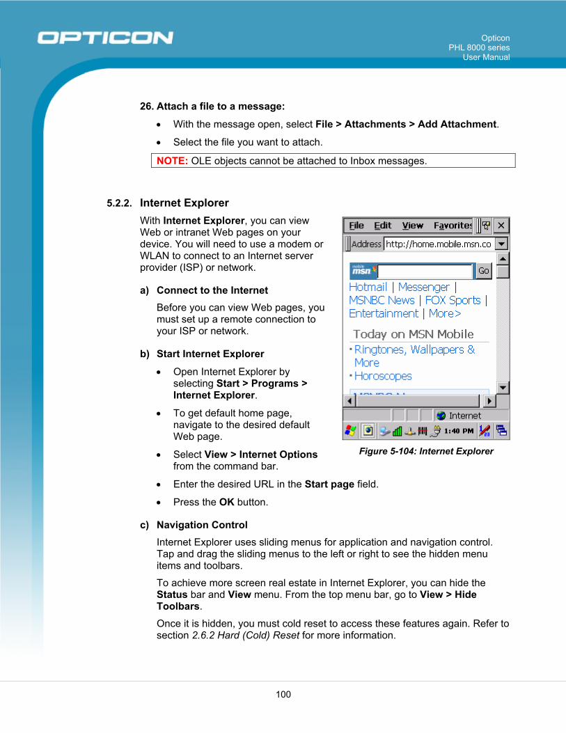
Opticon PHL 8000 series
User Manual
100
26. Attach a file to a message:
• With the message open, select File > Attachments > Add Attachment.
• Select the file you want to attach.
NOTE: OLE objects cannot be attached to Inbox messages.
5.2.2. Internet Explorer With Internet Explorer, you can view Web or intranet Web pages on your device. You will need to use a modem or WLAN to connect to an Internet server provider (ISP) or network.
a) Connect to the Internet Before you can view Web pages, you must set up a remote connection to your ISP or network.
b) Start Internet Explorer
• Open Internet Explorer by selecting Start > Programs > Internet Explorer.
• To get default home page, navigate to the desired default Web page.
• Select View > Internet Options from the command bar.
• Enter the desired URL in the Start page field.
• Press the OK button.
c) Navigation Control Internet Explorer uses sliding menus for application and navigation control. Tap and drag the sliding menus to the left or right to see the hidden menu items and toolbars.
To achieve more screen real estate in Internet Explorer, you can hide the Status bar and View menu. From the top menu bar, go to View > Hide Toolbars.
Once it is hidden, you must cold reset to access these features again. Refer to section 2.6.2 Hard (Cold) Reset for more information.
Figure 5-104: Internet Explorer
Opticon PHL 8000 series
User Manual
101
d) Set Up a Proxy Server Proxy servers are often used when connecting to the Internet through a local network, such as a corporate network, for added security.
• Select the View > Internet Options > Connection tab.
• Select Access the Internet using a proxy server.
• Enter the proxy server address and port. For more information, see your administrator.
• To bypass the proxy server for local address, such as corporate intranet pages, select Bypass proxy for local address.
e) Enable Cookies A cookie file contains information about your identity and preferences so that a Web site can tailor information to your needs. The Web site sends the file and it is stored on your mobile device.
• Select the View > Internet Options > Security tab.
• Select Allow cookies.
f) Search for an Internet Site
• Select View > Go > Search to search the Web.
g) Go to an Internet Address
• Select Address Bar, if necessary, to display the address bar.
• Enter the address.
• Press the Enter key.
h) View Previously Visited Sites
• Tap the arrow button at the right site of the Address Bar.
• Select the Web address you want to view.
i) Add and View Favorites
• Go to the page you want add
• Select Favorites > Add To Favorites.
• If necessary, locate the folder you want.
• Confirm or change the name.
• To view your favorite Web sites, select Favorites and the Web site you want to view.
NOTE: To organize your Favorites list, select Favorites > Organize Favorites.
Opticon PHL 8000 series
User Manual
102
j) Browse Web pages
• To move to a page you have previously view, select View > Back.
• To move to the next page (provided you have viewed it previously), select View > Forward.
• To return to your Home page, select View > Go > Home.
k) Refresh current page
• Select View > Refresh.
l) Stop loading a page
• Select View > Stop.
m) View current page
• Select View > Internet Options.
• To view the protocol, page type, size, and address, select the General tab.
• To view security information about the page, select the Security tab.
n) View HTML source code
• While viewing the page, select File > Save As and save the file as .txt file.
• Open the file in a word processing program, such as WordPad.
o) Change home and search page settings
• Open the page you want to use as your home or search page.
• Select View > Go > Home or Search.
p) Save a copy of current page You can save Web pages and view them later when you’re disconnected from the Internet or Intranet without using cached memory.
• Select File > Save As.
• Specify a folder location and give the file name.
q) Copy a Web page to a document
• Select all or part of the Web page you want to copy.
• Select Edit > Copy.
• Go to the document where you want to place the information and select the location.
• Select Edit > Paste.
Opticon PHL 8000 series
User Manual
103
r) Select security Options
• Select the View > Internet Options > Security tab.
• Select the security protocols you want.
s) Change the font size
• Select View > Text Size and select the desired size.
5.2.3. Microsoft WordPad You can create and edit documents and templates in WordPad, using buttons and menu commands that are similar to those used in the desktop version of Microsoft Word. You can work with files Normal or Outline view. WordPad documents are usually saved as .pwd files, but you can also save documents in other file formats, such as .rtf or .doc.
a) Selecting and Editing Text
• Select text:
To select Do this
Any amount of text Drag the stylus over the text.
A word Double-tap the word.
A single paragraph Triple-tap within the paragraph.
An entire document Select Edit > Select All.
An picture Tap the picture.
• Find text:
To search for text in one part of a document, select that part. Otherwise, the whole document is searched.
Select Edit > Find. Enter the text you want to find. For a paragraph, enter ^p. For a tab
stop, enter ^t. Select the search options you want. To continue searching, select Edit > Find > Next.
• Replace text:
To replace text in one part of document, select that part. Otherwise, the whole document is searched.
Select Edit > Replace. Enter the text you want to find and the text you want to replace it with.
For a paragraph, enter ^p. For a tab stop, enter ^t. Select the replacement options you want.
Opticon PHL 8000 series
User Manual
104
Select Find Next. On the Find/Replace toolbar, select the appropriate button.
• Move, copy, or delete text:
Select the text you want to move, copy, or delete. To move or delete text, select the Cut button. To copy the text, select
the Copy button. To paste the information, move the insertion point to the desired
location, and select the Paste button. NOTES: To undo an action, select Edit > Undo. To restore the action, select Edit > Redo.
b) Formatting Text
• Create bulleted and numbered lists:
Select the Bullets or Numbering button. Type the first item. Press Enter, type the next item, and repeat as needed. Select the button again to end list formatting.
NOTE: To change the number style for the selected list, select Format > Paragraph. In the Format list, select the style you want.
• Set the default font:
Select Format > Font. Select the font you want. Select Set As Default. To confirm that your changes will be applied to subsequent documents
you create, select Yes. NOTE: To apply the default font and stylus to selected text, select Apply Default.
• Select a different font:
Select the text you want to change. To select all text, select Edit > Select All.
From the Font list, select the font you want. From the Font Size list, select a size.
NOTE: To see more formatting options, select Format > Font.
• Change font formatting:
Select desired text. Select the Bold, Italic, or Underline button.
Opticon PHL 8000 series
User Manual
105
To change the color, select Format > Font and select the color you want from the Color list.
• Adjust the paragraph alignment:
Select the paragraph you want to align. Select the Align Left, Center, or Align Right button.
NOTE: To see more formatting options, select Format > Paragraph.
• Indent a paragraph:
Select the paragraph you want to indent. Select Format > Paragraph. Adjust the indentation settings as needed.
• Set tabs:
Select Format > Tabs. Change the tab settings as needed.
c) Adjusting the DisplayF
• Wrap text in the window:
Select View > Wrap to Window. • Display the document using the full screen:
Select View > Full Screen. To exit Full Screen view, select Restore. To move the Restore button, drag the bar on the left side.
• Display or hide scroll bars:
Select View > Horizontal Scroll Bar or Vertical Scroll Bar. • Zoom in or out:
Select View > Zoom, and select the desired percentage. NOTE: For Custom, enter the exact percentage and select OK.
d) Working in Outline View
• Switch between Normal and Outline views:
Select View > Normal or Outline. • Assign and change outline levels:
Select View > Outline. Select the appropriate buttons on the toolbar.
e) Inserting Symbols
• Place the insertion point where you want to insert the symbol:
Select Tools > Insert Symbols.

Opticon PHL 8000 series
User Manual
106
Select the symbol you want, and then select Insert. TIP: If you select a different font (or subset of a font), a different set of Symbols will be displayed.
f) Printing a Document
• Select File > Print.
• Select the printing options you want.
TIPS: Port lists the available printer ports.
If Network is selected from the Port list, enter the path to the network printer to the Net Path box.
g) Setting a Password for a Document
• Select File > Password.
• Type and verify the password.
• You must save the document (File > Save) to return the password.
h) Converting Documents About document conversion: If an email program is installed on your device and you receive an attached Word document or template created in Word version 6.0 or later, WordPad will convert the file on your device. To view the document, simply open the attachment in your email program or open the file in the WordPad.
During conversion, some formatting attributes may be changed or lost. To avoid losing these attributes permanently, close the file after viewing it rather saving the file on your device. If you save the file, save with a different file name.
For more information about conversion performed on your device, see the following topics.
i) Changes Caused by Word Document Conversion
• Formatting
Borders and Shading: Borders and shading are not displayed in WordPad, but are restored when converted back to a Word document. Shading is not restored when used in a table, but simple borders are restored.
Character formatting: Bold, italic, strikethrough, superscript, subscript, and hidden text are retained and displayed. Other effects are changed or removed.
Opticon PHL 8000 series
User Manual
107
Colors: Colors are retained and mapped to colors available on your device.
Fonts and font sizes: Fonts not supported by your mobile device are mapped to the closest font available in WordPad.
Page Formatting: Headers, footers, footnotes, columns, pages setup information, and style sheets are removed during conversion to WordPad. WordPad supports built-in headings.
Paragraph formatting: Tabs, alignment, bullets, indentation, simple numbered lists, and paragraph spacing are retailed and displayed in WordPad.
Pictures: Pictures are removed during conversion. Table of Contents: Table of Contents text and some formatting are
preserved. However, any text set at right-aligned tab stops may wrap to the next line.
Index: Index text and some formatting are preserved. Tables: Tables appear as tab-delimited text. Cells containing wrapped
text, tabs, or paragraph markers may be difficult to read. Simple tables are displayed accurately and restored when you convert the WordPad file back to a Word document.
OLE Objects: OLE objects are removed during conversion. Revision marks, annotations, and comments: Revision marks are
visible but cannot be changed. Annotations and documents are removed during conversion.
5.2.4. Remote Connection Using Remote Desktop Connection, you can log on to Windows Terminal Server and use all programs installed on this server. For example, instead of running Microsoft WordPad, you can run the desktop version of Microsoft Word.
a) Connecting to Terminal Server
• Select Start > Programs > Remote Connection, or run ‘CETSC’ from the command prompt.
• In the Server box, type or select a Terminal Server name or TCP/IP address, or select a server in the drop-down list.
• Select Connect.
• In the Remote Connection window, type your user name, password, and domain (if required), and then select OK.
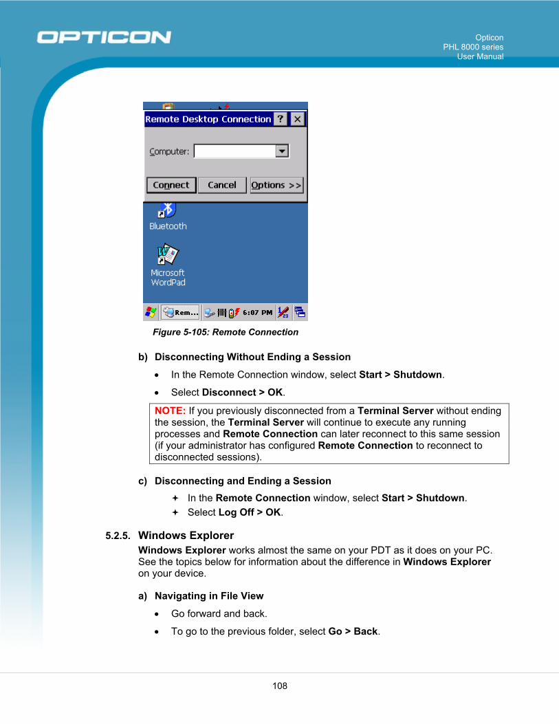
Opticon PHL 8000 series
User Manual
108
Figure 5-105: Remote Connection
b) Disconnecting Without Ending a Session
• In the Remote Connection window, select Start > Shutdown.
• Select Disconnect > OK.
NOTE: If you previously disconnected from a Terminal Server without ending the session, the Terminal Server will continue to execute any running processes and Remote Connection can later reconnect to this same session (if your administrator has configured Remote Connection to reconnect to disconnected sessions).
c) Disconnecting and Ending a Session In the Remote Connection window, select Start > Shutdown. Select Log Off > OK.
5.2.5. Windows Explorer Windows Explorer works almost the same on your PDT as it does on your PC. See the topics below for information about the difference in Windows Explorer on your device.
a) Navigating in File View
• Go forward and back.
• To go to the previous folder, select Go > Back.
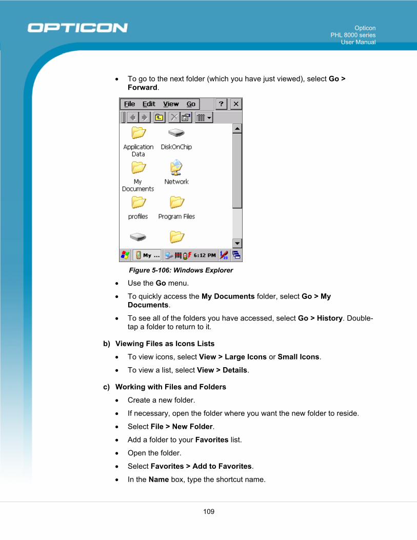
Opticon PHL 8000 series
User Manual
109
• To go to the next folder (which you have just viewed), select Go > Forward.
Figure 5-106: Windows Explorer
• Use the Go menu.
• To quickly access the My Documents folder, select Go > My Documents.
• To see all of the folders you have accessed, select Go > History. Double-tap a folder to return to it.
b) Viewing Files as Icons Lists
• To view icons, select View > Large Icons or Small Icons.
• To view a list, select View > Details.
c) Working with Files and Folders
• Create a new folder.
• If necessary, open the folder where you want the new folder to reside.
• Select File > New Folder.
• Add a folder to your Favorites list.
• Open the folder.
• Select Favorites > Add to Favorites.
• In the Name box, type the shortcut name.
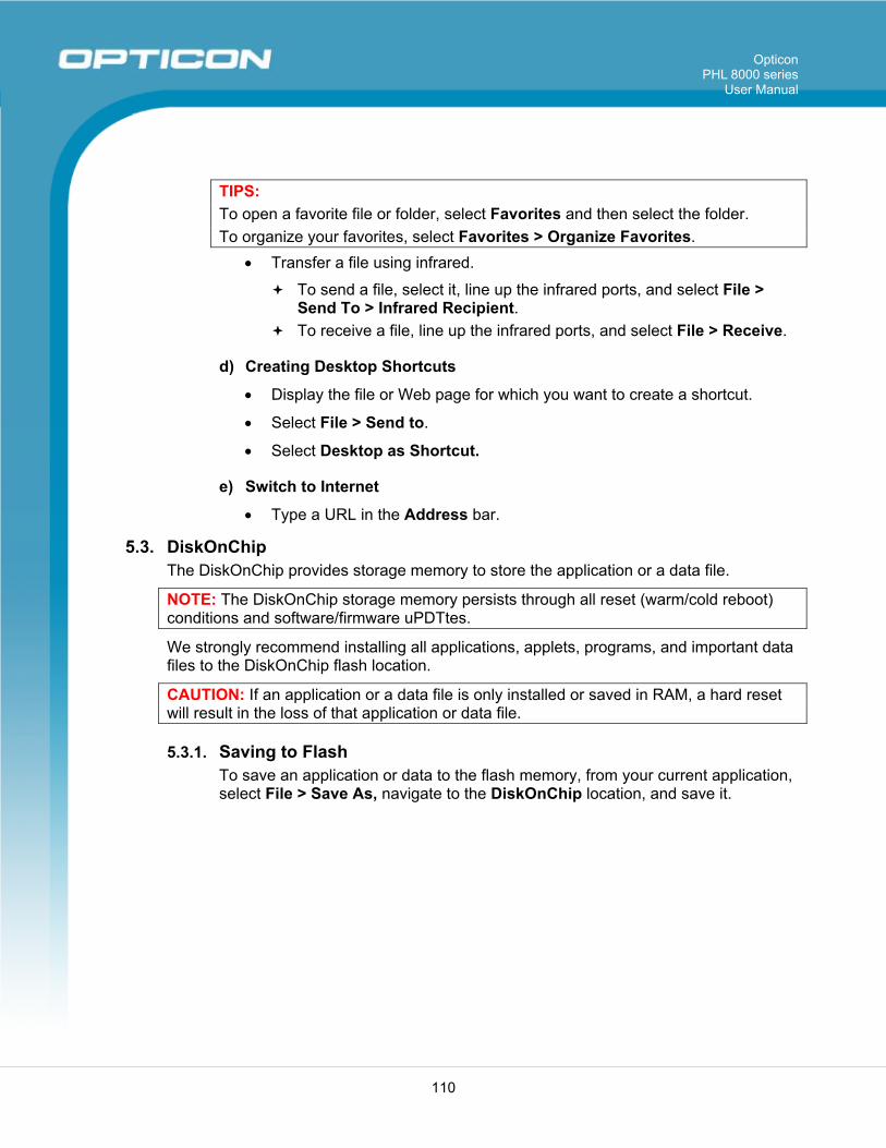
Opticon PHL 8000 series
User Manual
110
TIPS: To open a favorite file or folder, select Favorites and then select the folder. To organize your favorites, select Favorites > Organize Favorites.
• Transfer a file using infrared.
To send a file, select it, line up the infrared ports, and select File > Send To > Infrared Recipient.
To receive a file, line up the infrared ports, and select File > Receive.
d) Creating Desktop Shortcuts
• Display the file or Web page for which you want to create a shortcut.
• Select File > Send to.
• Select Desktop as Shortcut.
e) Switch to Internet
• Type a URL in the Address bar.
5.3. DiskOnChip The DiskOnChip provides storage memory to store the application or a data file.
NOTE: The DiskOnChip storage memory persists through all reset (warm/cold reboot) conditions and software/firmware uPDTtes.
We strongly recommend installing all applications, applets, programs, and important data files to the DiskOnChip flash location.
CAUTION: If an application or a data file is only installed or saved in RAM, a hard reset will result in the loss of that application or data file.
5.3.1. Saving to Flash To save an application or data to the flash memory, from your current application, select File > Save As, navigate to the DiskOnChip location, and save it.
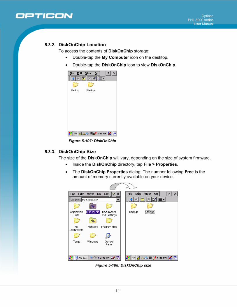
Opticon PHL 8000 series
User Manual
111
5.3.2. DiskOnChip Location To access the contents of DiskOnChip storage:
• Double-tap the My Computer icon on the desktop.
• Double-tap the DiskOnChip icon to view DiskOnChip.
Figure 5-107: DiskOnChip
5.3.3. DiskOnChip Size The size of the DiskOnChip will vary, depending on the size of system firmware.
• Inside the DiskOnChip directory, tap File > Properties.
• The DiskOnChip Properties dialog: The number following Free is the amount of memory currently available on your device.
Figure 5-108: DiskOnChip size
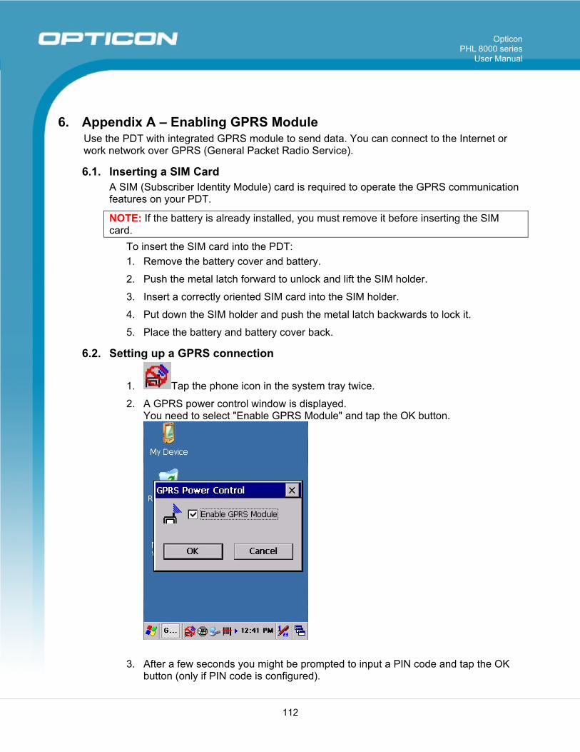
Opticon PHL 8000 series
User Manual
112
6. Appendix A – Enabling GPRS Module Use the PDT with integrated GPRS module to send data. You can connect to the Internet or work network over GPRS (General Packet Radio Service).
6.1. Inserting a SIM Card A SIM (Subscriber Identity Module) card is required to operate the GPRS communication features on your PDT.
NOTE: If the battery is already installed, you must remove it before inserting the SIM card.
To insert the SIM card into the PDT: 1. Remove the battery cover and battery.
2. Push the metal latch forward to unlock and lift the SIM holder.
3. Insert a correctly oriented SIM card into the SIM holder.
4. Put down the SIM holder and push the metal latch backwards to lock it.
5. Place the battery and battery cover back.
6.2. Setting up a GPRS connection
1. Tap the phone icon in the system tray twice.
2. A GPRS power control window is displayed. You need to select "Enable GPRS Module" and tap the OK button.
3. After a few seconds you might be prompted to input a PIN code and tap the OK button (only if PIN code is configured).
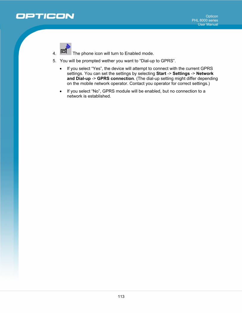
Opticon PHL 8000 series
User Manual
113
4. The phone icon will turn to Enabled mode.
5. You will be prompted wether you want to “Dial-up to GPRS”.
• If you select “Yes”, the device will attempt to connect with the current GPRS settings. You can set the settings by selecting Start -> Settings -> Network and Dial-up -> GPRS connection. (The dial-up setting might differ depending on the mobile network operator. Contact you operator for correct settings.)
• If you select “No”, GPRS module will be enabled, but no connection to a network is established.