ruska model 2475-610 pressure calibration system … · pressure calibration system model 2475-610...
TRANSCRIPT
RUSKA MODEL 2475-610 PRESSURE CALIBRATION SYSTEM USER’S MANUAL
PRESSURE CALIBRATION SYSTEM
MODEL 2475-610
USER'S MANUAL
RUSKA INSTRUMENT CORPORATION 10311 WESTPARK DRIVE, HOUSTON, TX. 77042
(713) 975-0547 FAX: (713) 975-6338 e-mail: [email protected] • http://www.ruska.com
Release: 2475-1D01 Revision: B
Date: August 12, 1992
WARRANTY
Ruska Instrument Corporation warrants its products to conform to or exceed the specifications as set forth in its catalogs in use at the time of sale and reserves the right, at its own discretion, without notice and without making similar changes in articles previously manufactured, to make changes in materials, designs, finish, or specifications. Ruska Instrument Corporation warrants products of its own factory against defects of material or workmanship for a period of one year from date of sale.
Liability of Ruska Instrument Corporation under this warranty shall be limited to replacing, free of charge (FOB Houston, Texas), any such parts proving defective within the period of this warranty, but Ruska Instrument Corporation will not be responsible for transportation charges or consequential damages.
The warranty of Ruska Instrument Corporation is not made for products manufactured by others which are illustrated and described in RUSKA catalogs or incorporated in RUSKA products in essentially the same form as supplied by the original manufacturer. With respect to the warranties of the original manufacturers supplant the warranty of Ruska Instrument Corporation, but, in applicable instances, the latter agrees to use its best efforts to have original suppliers make good their warranties.
INTRODUCTION -ii-

COPYRIGHT NOTICE
Copyright 1991, 1992 by Ruska Instrument Corporation. All rights reserved. This document may not be reproduced in part or in whole without the express written consent of Ruska Instrument Corporation.
DISCLAIMER
No representations or warranties are made with respect to the contents of this user's manual. Further, Ruska Instrument Corporation reserves the right to revise this manual and to make changes from time to time in the content hereof without obligation to notify any person of such revision.
TRADEMARK NOTICE
is a trademark of Ruska Instrument Corporation
Trademarks or tradenames are subject to state and federal laws concerning their unauthorized use or other infringements. The fact that the product marks or names in this manual do not bear a trademark symbol DOES NOT mean that the product name or mark is not registered as a trademark or tradename. Any queries concerning the ownership or existence of any trademarks or tradenames mentioned in this manual should be independently confirmed with the manufacturer or distributor of the product.
INTRODUCTION -iii-
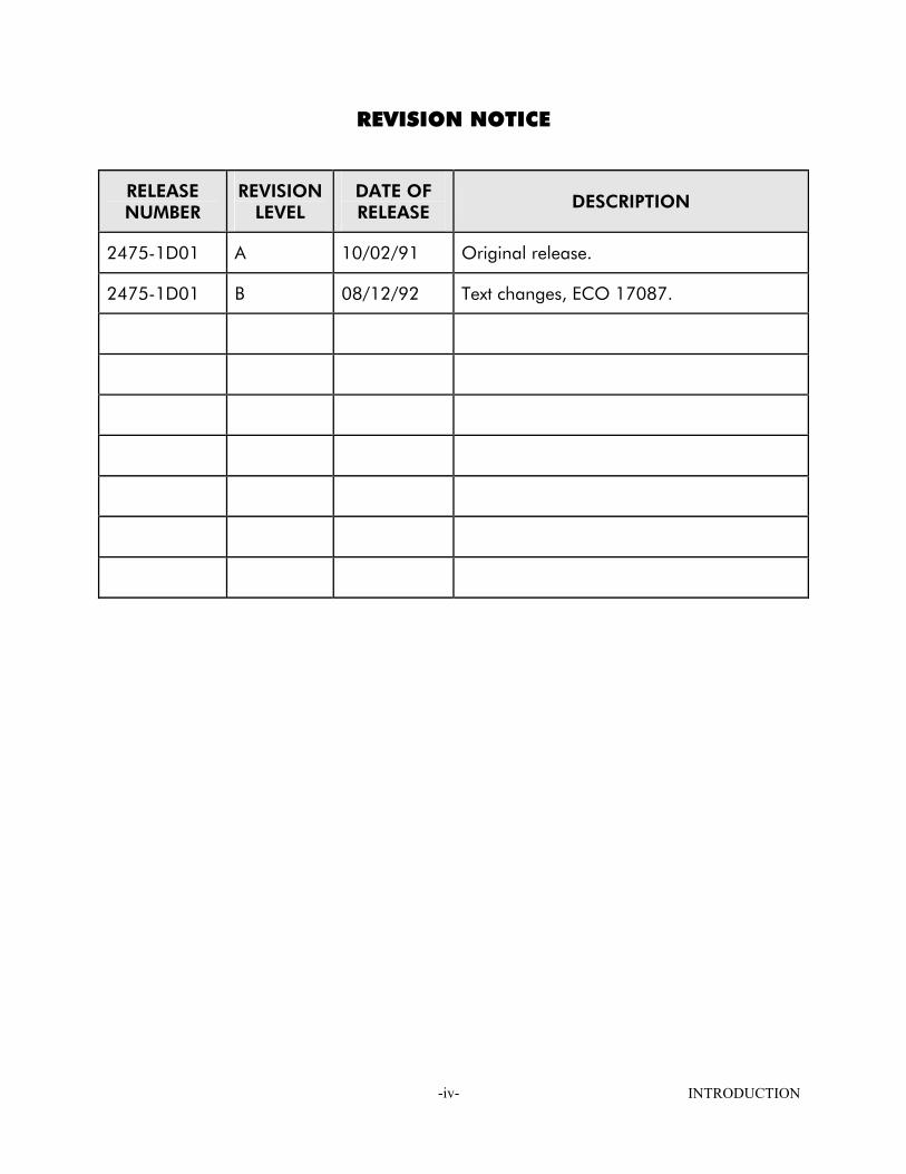
REVISION NOTICE
RELEASE NUMBER
REVISION LEVEL
DATE OF RELEASE
DESCRIPTION
2475-1D01 A 10/02/91 Original release.
2475-1D01 B 08/12/92 Text changes, ECO 17087.
INTRODUCTION -iv-
REVISION HISTORY
RELEASE 2475-1D01 Revision A (10/02/91) Original release - adapted from 2475-1D00-00001.
RELEASE 2475-1D01 Revision B (08/12/92) Added two references to Bibliography - section 2.9, ECO 17087
INTRODUCTION -v-
WARNING
PRESSURIZED VESSELS AND ASSOCIATED EQUIPMENT ARE POTENTIALLY DANGEROUS. THE APPARATUS DESCRIBED IN THIS MANUAL SHOULD BE OPERATED ONLY BY PERSONNEL TRAINED IN PROCEDURES THAT WILL ASSURE SAFETY TO THEMSELVES, TO OTHERS, AND TO THE EQUIPMENT.
DO NOT USE OXYGEN AS THE PRESSURE SUPPLY MEDIA; USE ONLY ZERO-GRADE HELIUM. INDUSTRIAL GRADE NITROGEN IS USED FOR DRIVING THE INTENSIFIER; IT MUST NOT BE USED AS THE CALIBRATING MEDIUM. DO NOT EXCEED SAFE MAXIMUM INLET PRESSURES AS FOLLOWS:
ZERO-GRADE HELIUM: 2200 PSI
INDUSTRIAL NITROGEN: 2200 PSI
DO NOT USE HYDROCARBON LUBRICANTS. USE ONLY RUSKA INSTRUMENT CORPORATION SUPPLIED LUBRICANT PART NUMBERS 45-338 (GREASE) AND 45-339 (OIL) UNLESS OTHERWISE SPECIFIED IN THIS MANUAL. ALWAYS USE REPLACEMENT PARTS SPECIFIED BY RUSKA INSTRUMENT CORPORATION.
WHEN ANY MAINTENANCE IS PERFORMED, TURN OFF POWER AND REMOVE POWER CORD.
INTRODUCTION -vi-
OXYGEN COMPATIBILITY
This instrument has been designed with components that will not introduce hydrocarbons into the calibration process. The o-ring and lubricating grease supplied with the instrument must not be substituted with other laboratory supplies.
Cleaning of the instrument for oxygen compatibility using liquid Freon and ultrasonic cleaning systems is permitted with the EXCEPTION OF THE PISTONS AND CYLINDERS. The Ruska procedures for piston/cylinder cleaning as described in Section 6.0 of this manual must be followed: ULTRASONIC CLEANING MAY DAMAGE THE CRYSTALLINE STRUCTURE OF THE TUNGSTEN CARBIDE PISTONS AND CYLINDERS.
INTRODUCTION -vii-
TABLE OF CONTENTS
WARRANTY...............................................................................................................-i- COPYRIGHT NOTICE ............................................................................................... -ii- REVISION NOTICE .................................................................................................. -iii- REVISION HISTORY ................................................................................................. -iv- WARNING ............................................................................................................... -v- OXYGEN COMPATIBILITY....................................................................................... -vii- TABLE OF CONTENTS............................................................................................ -vii- LIST OF FIGURES AND TABLES ................................................................................ -ix-
SECTION 1.0 SPECIFICATIONS 1.1 SPECIFICATIONS ................................................................................1-1
SECTION 2.0 CONSIDERATIONS 2.1 TYPES OF PISTON PRESSURE GAGES...................................................2-1 2.2 MEASUREMENT OF PRESSURE WITH THE PISTON PRESSURE GAGE ......2-3 2.3 ELASTIC DISTORTION OF THE CYLINDER............................................2-3 2.4 GRAVITY.............................................................................................2-3 2.5 BUOYANT EFFECT OF THE AIR............................................................2-3 2.6 TEMPERATURE ....................................................................................2-4 2.7 REFERENCE PLANE OF MEASUREMENT ...............................................2-5 2.8 CROSS-FLOATING..............................................................................2-5 2.9 BIBLIOGRAPHY ...................................................................................2-7
SECTION 3.0 DESCRIPTION OF APPARATUS 3.1 INTRODUCTION ................................................................................3-1 3.2 DESCRIPTION OF MODEL 2475 GAS-LUBRICATED PISTON PRESSURE GAGE 3-1 3.2.1 GENERAL INFORMATION .........................................................3-1 3.2.2 HOUSING ASSEMBLY ...............................................................3-4 3.2.3 MASS SET .................................................................................3-4 3.3 DESCRIPTION & FUNCTION OF 2475-610 PRESSURE CALIBRATION SYSTEM 3-4
SECTION 4.0 INSTALLATION 4.1 INSTALLATION OF THE APPARATUS ....................................................4-1
SECTION 5.0 PRESSURIZED SYSTEMS 5.1 PRECAUTIONS....................................................................................5-1 5.2 GAS-LUBRICATED PISTON PRESSURE GAGES ......................................5-2 5.3 PERFORMANCE OF THE MODEL 2475 PISTON PRESSURE GAGE .........5-2 5.4 REMOVAL OF THE PISTON-CYLINDER ASSEMBLY ................................5-2 5.5 PISTON/CYLINDER CLEANING INSTRUCTIONS...................................5-3 5.5.1 INTRODUCTION ......................................................................5-3 5.5.2 CLEANING WITH ORGANIC SOLVENTS ....................................5-3 5.5.3 CLEANING PROCEDURE USING SOAP AND WATER ..................5-3 5.5.4 CLEANING PROCEDURE USING FREON AND ALCOHOL ..........5-4 5.5.5 REASSEMBLY OF THE PISTON AND CYLINDER...........................5-6
INTRODUCTION -viii-
5.6 PRELIMINARY TEST PROCEDURES ........................................................5-7 5.7 CARE AND HANDLING OF THE MASSES ...........................................5-13 5.8 CALIBRATION OF ELASTIC SENSOR ..................................................5-13 5.8.1 OPERATION ...........................................................................5-13 5.8.1.1 INCREASING PRESSURES ...........................................5-13 5.8.1.2 DECREASING PRESSURES...........................................5-16
SECTION 6.0 SHUT-DOWN PROCEDURES 6.1 OPERATION .......................................................................................6-1
APPENDIX A: CALCULATIONS
APPENDIX B: PRESSURE INTENSIFIER SYSTEM
APPENDIX C: RUSKA HAND PUMP
APPENDIX D: CATALOG INFORMATION
APPENDIX E: DRAWINGS AND BILLS-OF-MATERIALS
APPENDIX F: TEST AND CALIBRATION REPORTS
INTRODUCTION -ix-
LIST OF FIGURES AND TABLES
FIGURE 2-1: Simple Cylinder...................................................................................2-1 FIGURE 2-2: Re-Entrant Cylinder .............................................................................2-1 FIGURE 2-3: Controlled Clearance Cylinder.............................................................2-1 FIGURE 3-1: Model 2475-610 Pressure Calibration System ......................................3-2 FIGURE 3-2: Piston/Cylinder Assembly.....................................................................3-3 FIGURE 4-1: High Pressure Coned and Threaded Connection...................................4-1 FIGURE A-1: Nitrogen Density (English Units to 1,000 PSIG) .....................................A-7 FIGURE A-2: Nitrogen Density (English Units 1,000 PSIG to 15,000 PSIG) .................A-8 FIGURE A-3: Nitrogen Density (SI Units to 10 MPa)...................................................A-9 FIGURE A-4: Nitrogen Density (SI Units 10 to 100 MPa), .........................................A-10 FIGURE A-5: Temperature Correction (SI Units To 100 MPa). ..................................A-14 FIGURE A-6: Temperature Correction (English Units To 1000 PSI)............................A-15 FIGURE A-7: Temperature Correction (English Units TO 16000 PSI).........................A-16 FIGURE B-1: Piping Schematic.................................................................................B-2 FIGURE B-2: Ruska Pressure Intensifier Cat. No. 2440..............................................B-4 FIGURE B-3: Check Valve .....................................................................................B-6 FIGURE C-1: Ruska Hand Pump Cat. No. 2426-825................................................ C-2 TABLE A-1: Standard Press. for Piston Pressure Gage (English) ................................A-5 TABLE A-2: Standard Press. for Piston Pressure Gage (SI) ........................................A-6 TABLE A-3: Air Density ...................................................................................A-11 TABLE A-4: Conversion Factors............................................................................A-17
INTRODUCTION -x-

SECTION 1.0 SPECIFICATIONS
1.1 SPECIFICATIONS
Pressure Range: 3.4 to 100 MPa (500 to 15,000 psig)
Humidity range: Operation: Storage:
20 to 75% 0 to 90%
Accuracy: 0.01% of reading or 0.1 psi, whichever is greater, traceable to the NIST
Pressure medium:
Zero-Grade Helium
Sensitivity threshold*: 0.0001% (1 ppm) Fittings: two 1/8-in. female NPT with 3/16-in. RUSKA male nipples installed
Repeatability: 0.0003% (3 ppm). Reproducibility 0.0006%/yr (6 ppm). Test pressure
(housing): 150 MPa (22,500 psi)
Sink rate: 4 mm (0.15 in.) per minute, maximum
Electrical requirement:
115V, 60Hz, 5VA (for 2475-601 system)
Instrument base size:
33.0 cm (13 in.) long 35.6 cm (14 in.) wide 45.7 cm (18 in.) high
Piston/Cylinder material:
tungsten carbide
Thermal coefficient: 9.1 x 10⁻⁶ per oC Mass case seize: First case:
40.6 cm (16 in.) long
Mass material: nonmagnetic, austenitic (300 series) stainless steel
Additional cases** Each
33.0 cm (13 in.) long 25.4 cm (10 in.) wide 33.0 cm (13 in.) high
Mass, maximum error in reported value:
10 ppm or 1.0 x 10⁻⁶ kg, whichever is greater
Weight: Instrument base:
13.5 kg (30 lb)
Trim masses: Class "S" trim mass set provided
Mass set in cases: First case:
15.9 kg (35 lb)
Temperature range: Operation: Strorage:
18 to 28oC -40 to 70oC
Additional cases** Each:
22.7 kg (50 lb)
* International Recommendation, International Organization of Legal Metrology. ** Four of these boxes are required for the 90-kg mass set. Three are required for the
60-kg mass set. Only one is required for the 30-kg set.
SPECIFICATIONS 1-1

THIS PAGE INTENTIONALLY LEFT BLANK
SPECIFICATIONS 1-2
SECTION 2.0 CONSIDERATIONS
2.1 TYPES OF PISTON PRESSURE GAGES The piston pressure gage is sometimes regarded as an absolute instrument because of the principle by which it measures pressure. An absolute instrument is defined here as one capable of measuring a quantity in the fundamental units of mass, length, time, etc. It may be suggested that only certain types of piston pressure gages qualify in this category.
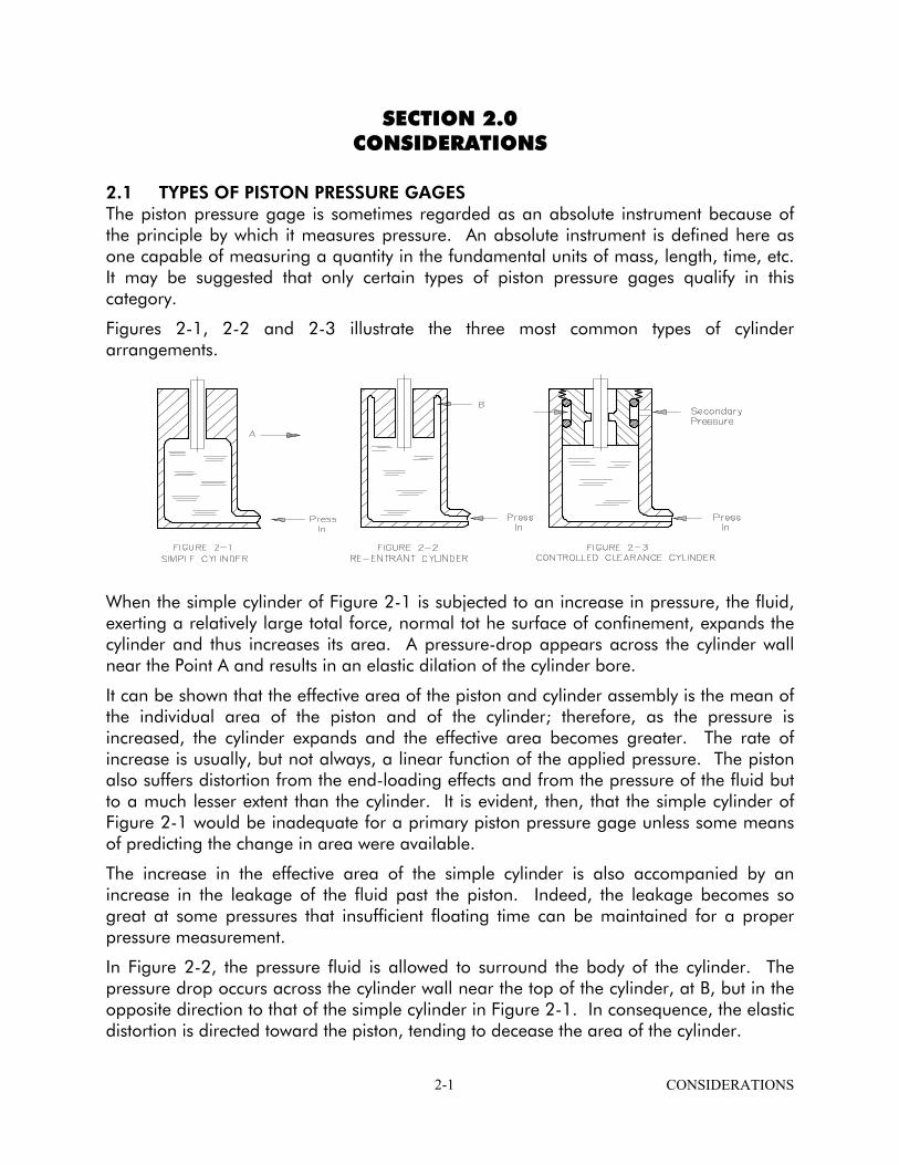
Figures 2-1, 2-2 and 2-3 illustrate the three most common types of cylinder arrangements.
When the simple cylinder of Figure 2-1 is subjected to an increase in pressure, the fluid, exerting a relatively large total force, normal tot he surface of confinement, expands the cylinder and thus increases its area. A pressure-drop appears across the cylinder wall near the Point A and results in an elastic dilation of the cylinder bore.
It can be shown that the effective area of the piston and cylinder assembly is the mean of the individual area of the piston and of the cylinder; therefore, as the pressure is increased, the cylinder expands and the effective area becomes greater. The rate of increase is usually, but not always, a linear function of the applied pressure. The piston also suffers distortion from the end-loading effects and from the pressure of the fluid but to a much lesser extent than the cylinder. It is evident, then, that the simple cylinder of Figure 2-1 would be inadequate for a primary piston pressure gage unless some means of predicting the change in area were available.
The increase in the effective area of the simple cylinder is also accompanied by an increase in the leakage of the fluid past the piston. Indeed, the leakage becomes so great at some pressures that insufficient floating time can be maintained for a proper pressure measurement.
In Figure 2-2, the pressure fluid is allowed to surround the body of the cylinder. The pressure drop occurs across the cylinder wall near the top of the cylinder, at B, but in the opposite direction to that of the simple cylinder in Figure 2-1. In consequence, the elastic distortion is directed toward the piston, tending to decease the area of the cylinder.
CONSIDERATIONS 2-1
Again, the change in area with changing pressure places a limit on the usefulness of cylinder Figure 2-2 as a primary instrument. But some benefit results from the use of cylinder Figure 2-2 in the construction of a piston pressure gage because higher pressures may be attained without a loss in float time. A small sacrifice is made in the float time at lower pressures because the total clearance between piston and cylinder must necessarily be greater at low pressure for cylinder Fig. 2-2 than for cylinder Fig. 2-1.
In the controlled-clearance design of Figure 2-3 , the cylinder is surrounded by a jacket to which a secondary fluid pressure system is connected. Adjustment of the secondary, or jacket, pressure permits the operator to change the clearance between the cylinder and piston at will. A series of observations involving piston sink rates at various jacket pressures leads to the empirical determination of the effective area of the assembly. In the United States, the controlled-clearance piston pressure gage is the accepted standard of pressure at levels higher than those that are practical for the mercury manometer.
Piston pressure gages having very high resolutions may be made by using simple and reentrant cylinders. A determination of the distortion coefficients of such gages may be made by direct comparison with a controlled-clearance gage. Most piston pressure gages have some elastic distortion, but some, used in the very low pressures, have only small coefficients and, in some instances, correction for distortion may be neglected.
Measurement of pressure with the piston pressure gage is subject to uncertainties resulting from effects other than those of elastic distortion. But, it was appropriate that the subject of elastic distortion be discussed first, since this characteristic is largely responsible for the various designs that have been developed.
Measurement processes proposed for high accuracy are disturbed by limitations in the performance of the equipment, by small changes in the environment and by operational procedures. The disturbances can be reduced to a degree by exercising control of the apparatus. Some of the disturbances are difficult to control; it is easier to observe their magnitudes and apply corrections for their effects.
The factors that affect a pressure measurement process when conducted with a piston pressure gage are described below. It is important that the operator acquaint himself with these factors and become accustomed to recognizing their presence. The success of the measurement will depend upon the degree to which control has been maintained or to the completeness by which corrections were applied for these factors.
Elastic distortions of the piston and cylinder. Effects of gravity on the masses. Temperature of the piston and cylinder. Buoyant effect of the atmosphere upon the masses. Hydraulic and gaseous pressure gradients within the apparatus. Surface tension effects of the liquids.
The RUSKA Instrument system uses the RE-ENTRANT type piston pressure gage.
CONSIDERATIONS 2-2
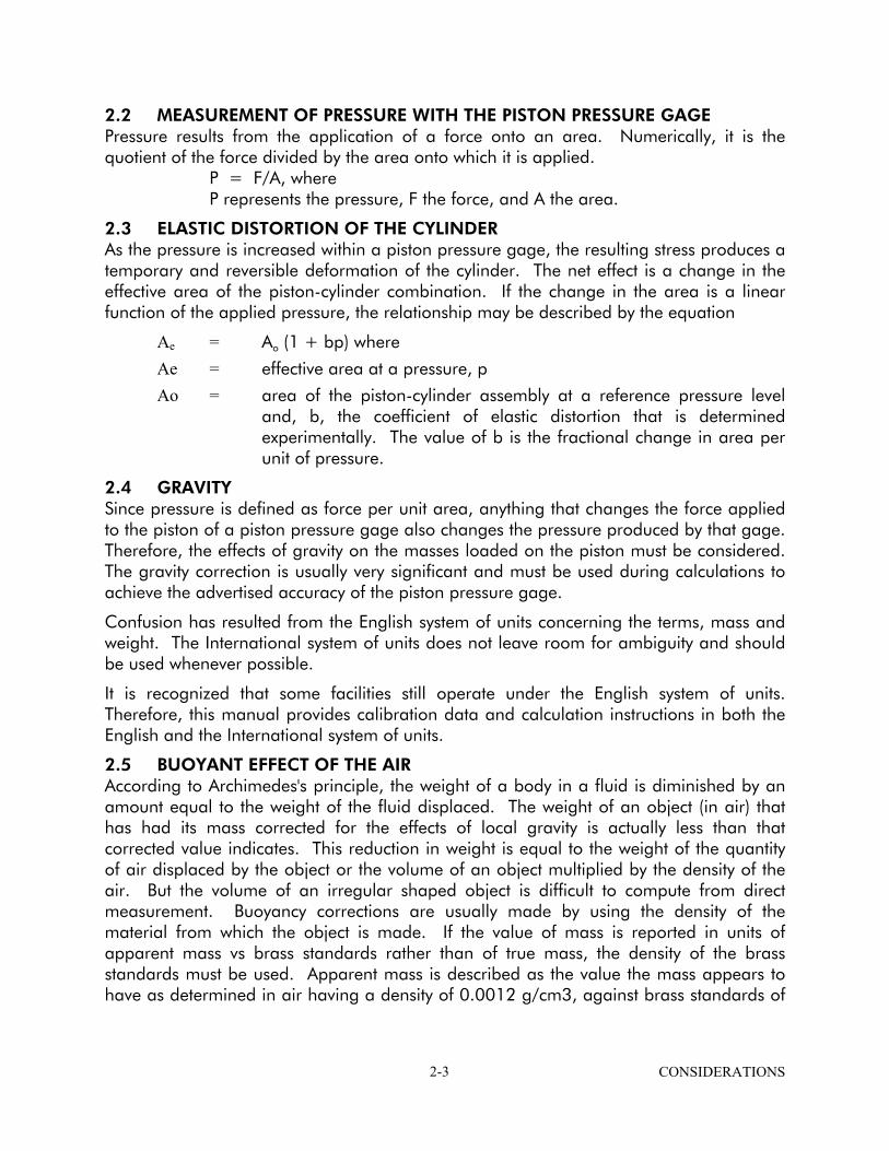
2.2 MEASUREMENT OF PRESSURE WITH THE PISTON PRESSURE GAGE Pressure results from the application of a force onto an area. Numerically, it is the quotient of the force divided by the area onto which it is applied. P = F/A, where P represents the pressure, F the force, and A the area.
2.3 ELASTIC DISTORTION OF THE CYLINDER As the pressure is increased within a piston pressure gage, the resulting stress produces a temporary and reversible deformation of the cylinder. The net effect is a change in the effective area of the piston-cylinder combination. If the change in the area is a linear function of the applied pressure, the relationship may be described by the equation
Ae = Ao (1 + bp) where
Ae = effective area at a pressure, p
Ao = area of the piston-cylinder assembly at a reference pressure level and, b, the coefficient of elastic distortion that is determined experimentally. The value of b is the fractional change in area per unit of pressure.
2.4 GRAVITY Since pressure is defined as force per unit area, anything that changes the force applied to the piston of a piston pressure gage also changes the pressure produced by that gage. Therefore, the effects of gravity on the masses loaded on the piston must be considered. The gravity correction is usually very significant and must be used during calculations to achieve the advertised accuracy of the piston pressure gage.
Confusion has resulted from the English system of units concerning the terms, mass and weight. The International system of units does not leave room for ambiguity and should be used whenever possible.
It is recognized that some facilities still operate under the English system of units. Therefore, this manual provides calibration data and calculation instructions in both the English and the International system of units.
2.5 BUOYANT EFFECT OF THE AIR According to Archimedes's principle, the weight of a body in a fluid is diminished by an amount equal to the weight of the fluid displaced. The weight of an object (in air) that has had its mass corrected for the effects of local gravity is actually less than that corrected value indicates. This reduction in weight is equal to the weight of the quantity of air displaced by the object or the volume of an object multiplied by the density of the air. But the volume of an irregular shaped object is difficult to compute from direct measurement. Buoyancy corrections are usually made by using the density of the material from which the object is made. If the value of mass is reported in units of apparent mass vs brass standards rather than of true mass, the density of the brass standards must be used. Apparent mass is described as the value the mass appears to have as determined in air having a density of 0.0012 g/cm3, against brass standards of
CONSIDERATIONS 2-3

a density of 8.4 g/cm3, whose coefficient of cubical expansion is 5.4 x 10⁻⁵/oC, and whose value is based on true mass in value (see reference 4).
Although the trend is swinging toward the use of true mass in favor of apparent mass, there is a small advantage in the use of the latter. When making calculations for air buoyancy from values of apparent mass, it is unnecessary to know the density of the mass. If objects of different densities are included in the calculation, it is not necessary to distinguish the difference in the calculations. This advantage is obtained at a small sacrifice in accuracy and is probably not justified when considering the confusion that is likely to occur if it becomes necessary to alternate in the use of the two systems.
A satisfactory approximation of the force on a piston that is produced by the load is given by
F = MA (1 - Da/Db) k g1 Where: F = the force on the piston MA = Mass of the load, reported as "apparent mass vs brass standards" Da = Density of the air Db = Density of brass (8.4 g/cm3) k = Constant g1 = acceleration due to local gravity
2.6 TEMPERATURE Piston pressure gages are temperature sensitive and must, therefore, be corrected to a common temperature datum.
Variations in the indicated pressure resulting from changes in temperature arise from the change in effective area of the piston due to expansion or contractions caused by temperature changes. The solution is a straightforward application of the thermal coefficients of the materials of the piston and cylinder. The area corresponding to the new temperature may be found by substituting the difference in working temperature from the reference temperature and the thermal coefficient of area expansion in the relation as follows:
Ao(t) = Ao(Ref. t) (1 + C dt)
In the equation above,
Ao(t) = Area corrected to the working temperature. Ao(Ref. t) = Area of the piston at zero PSIG and at the selected reference
temperature. C = Coefficient of superficial expansion as indicated in the test report. dt = Difference between working temperature and reference temperature.
CONSIDERATIONS 2-4
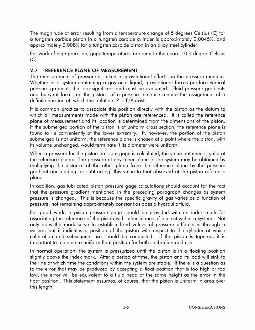
The magnitude of error resulting from a temperature change of 5 degrees Celsius (C) for a tungsten carbide piston in a tungsten carbide cylinder is approximately 0.0045%, and approximately 0.008% for a tungsten carbide piston in an alloy steel cylinder.
For work of high precision, gage temperatures are read to the nearest 0.1 degree Celsius (C).
2.7 REFERENCE PLANE OF MEASUREMENT The measurement of pressure is linked to gravitational effects on the pressure medium. Whether in a system containing a gas or a liquid, gravitational forces produce vertical pressure gradients that are significant and must be evaluated. Fluid pressure gradients and buoyant forces on the piston of a pressure balance require the assignment of a definite position at which the relation P = F/A exists
It is common practice to associate this position directly with the piston as the datum to which all measurements made with the piston are referenced. It is called the reference plane of measurement and its location is determined from the dimensions of the piston. If the submerged portion of the piston is of uniform cross section, the reference plane is found to lie conveniently at the lower extremity. If, however, the portion of the piston submerged is not uniform, the reference plane is chosen at a point where the piston, with its volume unchanged, would terminate if its diameter were uniform.
When a pressure for the piston pressure gage is calculated, the value obtained is valid at the reference plane. The pressure at any other plane in the system may be obtained by multiplying the distance of the other plane from the reference plane by the pressure gradient and adding (or subtracting) this value to that observed at the piston reference plane.
In addition, gas lubricated piston pressure gage calculations should account for the fact that the pressure gradient mentioned in the preceding paragraph changes as system pressure is changed. This is because the specific gravity of gas varies as a function of pressure, not remaining approximately constant as does a hydraulic fluid.
For good work, a piston pressure gage should be provided with an index mark for associating the reference of the piston with other planes of interest within a system. Not only does the mark serve to establish fixed values of pressure differences through a system, but it indicates a position of the piston with respect to the cylinder at which calibration and subsequent use should be conducted. If the piston is tapered, it is important to maintain a uniform float position for both calibration and use.
In normal operation, the system is pressurized until the piston is in a floating position slightly above the index mark. After a period of time, the piston and its load will sink to the line at which time the conditions within the system are stable. If there is a question as to the error that may be produced by accepting a float position that is too high or too low, the error will be equivalent to a fluid head of the same height as the error in the float position. This statement assumes, of course, that the piston is uniform in area over this length.
CONSIDERATIONS 2-5
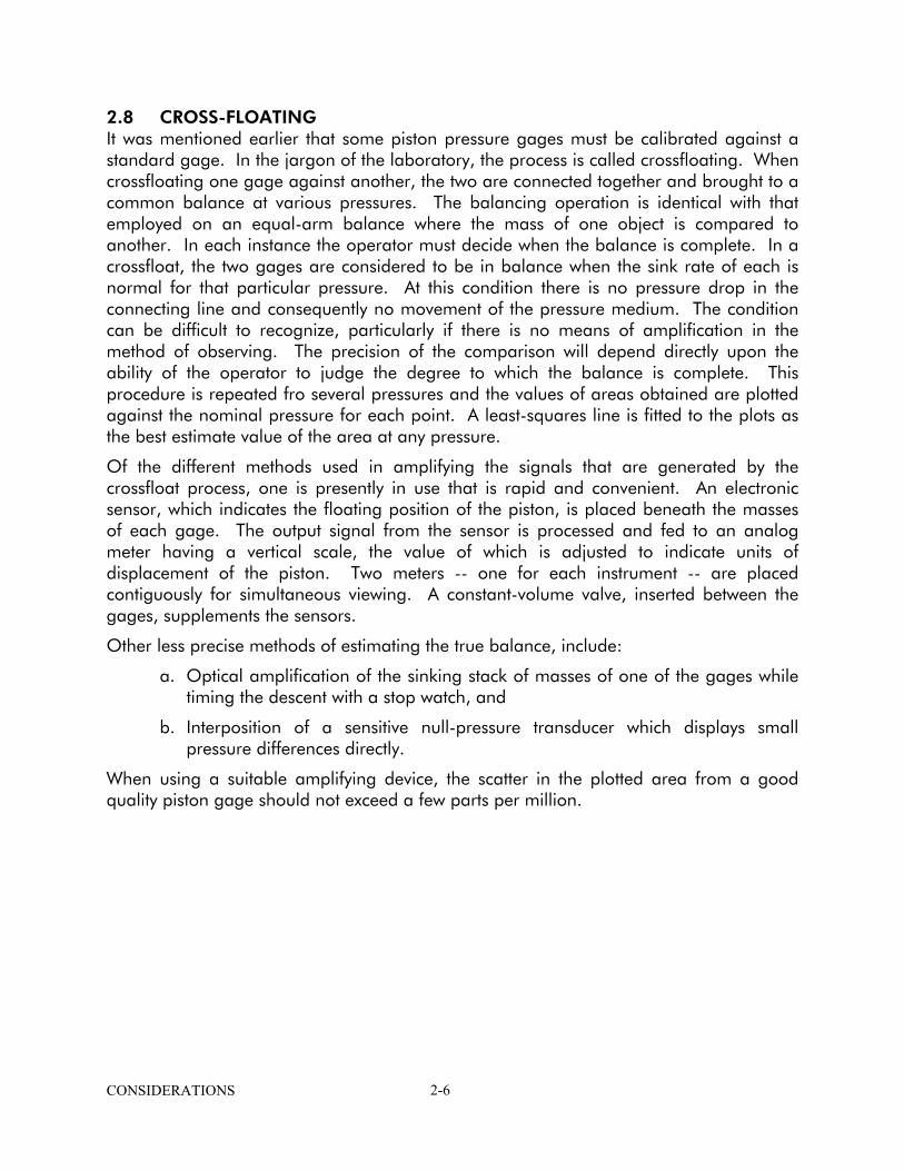
2.8 CROSS-FLOATING It was mentioned earlier that some piston pressure gages must be calibrated against a standard gage. In the jargon of the laboratory, the process is called crossfloating. When crossfloating one gage against another, the two are connected together and brought to a common balance at various pressures. The balancing operation is identical with that employed on an equal-arm balance where the mass of one object is compared to another. In each instance the operator must decide when the balance is complete. In a crossfloat, the two gages are considered to be in balance when the sink rate of each is normal for that particular pressure. At this condition there is no pressure drop in the connecting line and consequently no movement of the pressure medium. The condition can be difficult to recognize, particularly if there is no means of amplification in the method of observing. The precision of the comparison will depend directly upon the ability of the operator to judge the degree to which the balance is complete. This procedure is repeated fro several pressures and the values of areas obtained are plotted against the nominal pressure for each point. A least-squares line is fitted to the plots as the best estimate value of the area at any pressure.
Of the different methods used in amplifying the signals that are generated by the crossfloat process, one is presently in use that is rapid and convenient. An electronic sensor, which indicates the floating position of the piston, is placed beneath the masses of each gage. The output signal from the sensor is processed and fed to an analog meter having a vertical scale, the value of which is adjusted to indicate units of displacement of the piston. Two meters -- one for each instrument -- are placed contiguously for simultaneous viewing. A constant-volume valve, inserted between the gages, supplements the sensors.
Other less precise methods of estimating the true balance, include:
a. Optical amplification of the sinking stack of masses of one of the gages while timing the descent with a stop watch, and
b. Interposition of a sensitive null-pressure transducer which displays small pressure differences directly.
When using a suitable amplifying device, the scatter in the plotted area from a good quality piston gage should not exceed a few parts per million.
CONSIDERATIONS 2-6
2.9 BIBLIOGRAPHY
1. Bridgman, P. W., The Physics of High Pressure, G. Bell & Sons, London, 1952.
2. Cross, J.L., "Reduction of Data for Piston Gage Pressure Measurements". NBS Monograph 65 (1963).
3. Dadson, R.S., "The Accurate Measurement of High Pressures and the Precise Calibration of Pressure Balances:, Proc. Conf. Thermodynamic and Transport Properties of Fluids, London, pp. 32-42, 1957, Institute of Mechanical Engineers.
4. "Design and test of Standards of Mass", NBS Circular No. 3 (Dec., 1918), Included in NBS Handbook 77, Volume III.
5. Johnson, D.P., J.L. Cross, J.D. Hill, and H.A. Bowman, "Elastic distortion Error in the Dead Weight Piston Gage", Ind. Engineering Chem., 40, 2046 (Dec., 1957).
6. Johnson, D.P., and D. H. Newhall, "The Piston Gage is a Precise Measuring Instrument", Trans. of ASME, APril, 1953.
7. Newhall, D.H. and L. H. Abbot, "Controlled-Clearance Piston Gage", Measurements and Data, Jan.-Feb. 1970.
8. "Pressure Measurement", Measurements & Data Home Study Course, No. 17, Measurements and Data. September-October, 1969.
9. Tate, D.R., Gravity Measurements and the Standards Laboratory, National Bureau of Standards Technical Note No. 491 (1969).
10. Heydemann and Welch, Chapter 4, Part 3, "Pure and APplied Chamistry", Butterworths.
11. Kirk K. Mosher, Ruska Instrument Corporation, "The traceability Chain of the Piston Pressure Gage to NIST", presented at the Canadian National Conference of Standards Laboratories, 1991.
12. Ken Kolb, Ruska Instrument Corporation, "Reduced Uncertainty and Improved Reliability for the Pneumatic Piston Pressure Gage Through Statistical Process Control" published in the "Proceedings" for the Annual Measurement Science Conference, 1991.
CONSIDERATIONS 2-7

THIS PAGE INTENTIONALLY LEFT BLANK
CONSIDERATIONS 2-8

SECTION 3.0 DESCRIPTION OF APPARATUS
3.1 INTRODUCTION Pressure gages and pressure transducers which are used on, or in support equipment for air and spacecraft, operate with various gases that are often critical to the performance of these devices. Low-pressure gages present no serious problems since adequate equipment has been developed for satisfying the requirements of successful operation. High-pressure gas calibrations, however, have been hindered by the shortage of standards capable of achieving this function directly. Technology for advancing the state-of-the-art calibration standards has been hard-pressed by perpetual refinements in the behavior of the indicating instruments themselves. Improvements in construction materials, dimensional measurement capabilities and in manufacturing skills have given rise to new concepts in the design of laboratory standards of pressure. The gas-lubricated piston pressure gage is one of those instruments that has benefited from these new technologies. A piston gage has been developed that will operate with gas as the pressure medium at levels as high as 1,000 atmospheres and with the accuracy that may be expected of a present-day calibration standard. The pressurizing medium for the piston gage is the same gas as that used for the device being calibrated. Fluid separators, interfaces or lubricators (sources of process disturbances) are not required in the operation of this gage.
3.2 DESCRIPTION OF THE RUSKA MODEL 2475 GAS-LUBRICATED PISTON PRESSURE GAGE
3.2.1 GENERAL INFORMATION The Ruska Model 2475 Gas-lubricated Piston Pressure Gage (hereafter called GLPPG) was designed as a laboratory reference of pressure. It permits measurement of pneumatic pressures to 15,000 psi without the use of oil as the pressure medium or as a seal for the piston. Design criteria necessary for assurance of high performance of this GLPPG suggested that the masses be rotated by hand rather than with a motor. The high level of performance that is characteristic of this gage is credited to, among other things, its simplicity. Absence of the secondary piston, common to many Ruska piston gages, calls for carefully-executed operating procedures. The gain in behavior, from the simplistic design, is worth the care and manual dexterity that must be applied. Operating skills for fulfillment of these requirements are quickly acquired. The piston must be protected from transient side-loading effects that are caused by perfunctory mass-loading procedures. When the masses are loaded on the mass table or hanger, they must be applied with such care that it will be certain that the action is reliable. In general, it is advisable to load the masses when the piston is in its "down" position. As such, there is small probability of damage because of its disengagement with the load-transmitting table support. There are occasions, however, when the piston will be extended from its cylinder to the fullest and must have an exchange of masses
DESCRIPTION OF APPARATUS 3-1
while in this condition. It is at these moments when the concentration must be intense in the performance of the exchange.
Refer to Figures 3-1 and 3-2 for location of items discussed in the following paragraphs.
FIGURE 3-1
MODEL 2475-610 PRESSURE CALIBRATION SYSTEM
DESCRIPTION OF APPARATUS 3-2

FIGURE 3-2
PISTON/CYLINDER ASSEMBLY
DESCRIPTION OF APPARATUS 3-3

3.2.2 HOUSING ASSEMBLY The mass-loading table transfers the load generated by the chosen masses to the piston. The mass table is not attached to the piston coupling is made only when the piston rises in response to pressure in the GLPPG. A thrust bearing provides a definite stop for preventing the piston from being forced out of its cylinder when the system is overpressured. This bearing can withstand full-scale pressure overrange without damage. The thrust bearing also prevents the piston from receiving impact when masses fall freely from a floating position. Such action occurs when a vent vale is opened.
The sleeve mass hangs from the mass table and acts as a carrier for the mass set.
The cylinder is of the re-entrant design which enables the gage to operate over a wide range of pressures without excessive gas leakage.
A snap ring on the piston aids in removal of the cylinder from the housing.
The height rod is scribed with index lines which are used to indicate the assigned float position of the piston and the range to which it is restricted. The area of the piston is known only at its mid floating range position. Use of the index lines will be discussed in another section of this manual.
3.2.3 MASS SET All masses supplied with this GLPPG are made of non-magnetic, austenitic (series 300) stainless steel. They are machined from rolled stock or forgings, and the removal of any metal is performed in such a way as to maintain balance about the centerline. Final mass adjustment is usually accomplished by drilling a symmetrical pattern of holes concentric with the axis.
3.3 DESCRIPTION AND FUNCTION OF THE RUSKA MODEL 2475-610 PRESSURE CALIBRATION SYSTEM
Though some piston pressure gages may be purchased as individual sensing devices for connection to the customer's existing ancillary equipment, the operating characteristics of the Model 2475 piston gage indicate good reason to offer this instrument as a part of a turnkey system that has been assembled, tested and adjusted at the factory.
The Model 2475-610 Pressure Calibration System is complete in its function to serve as an independent unit for the calibration of secondary gas-operated pressure sensors. The customer is required to furnish only a supply of industrial-grade nitrogen and purified helium for the operation of the system. Helium is used as the pressure calibration medium while nitrogen provides the source of driving power for the pressure intensifier. The range of operation is listed in the table of specifications for Model 2475-900 Piston Pressure Gage.
After factory testing, the system is disassembled only to the extent necessary for safe shipment to its destination. Reassembly consists of placing the piston gage in position and coupling the connections for the gage and for the supply bottles. Installation and operation of the gage and of the system will be described under their respective subtitles.
DESCRIPTION OF APPARATUS 3-4
SECTION 4.0 INSTALLATION
4.1 RUSKA MODEL 2475-610 PRESSURE CALIBRATION SYSTEM INSTALLATION OF THE APPARATUS
Upon receipt of the shipment, the worktable should be removed from its shipping crate and positioned within the laboratory. Its location should be governed by its isolation from personnel traffic, protection from local wind drafts and in a region with minimum air-conditioning temperature ripple. After removal of the piston gage from its portion of the crate, the gage should be placed on the table as indicated by the system layout diagram in the manual BUT ONLY WITH THE CIRCULAR FOOT PLATES BENEATH THE LEVEL SCREWS AND REAR SUPPORT. If the gage is placed on the table without the foot plates, the level screw ends will puncture the finish and expose the wood beneath to entrance of surface soil. The final position of the gage will be determined by the connecting the pressure tube.
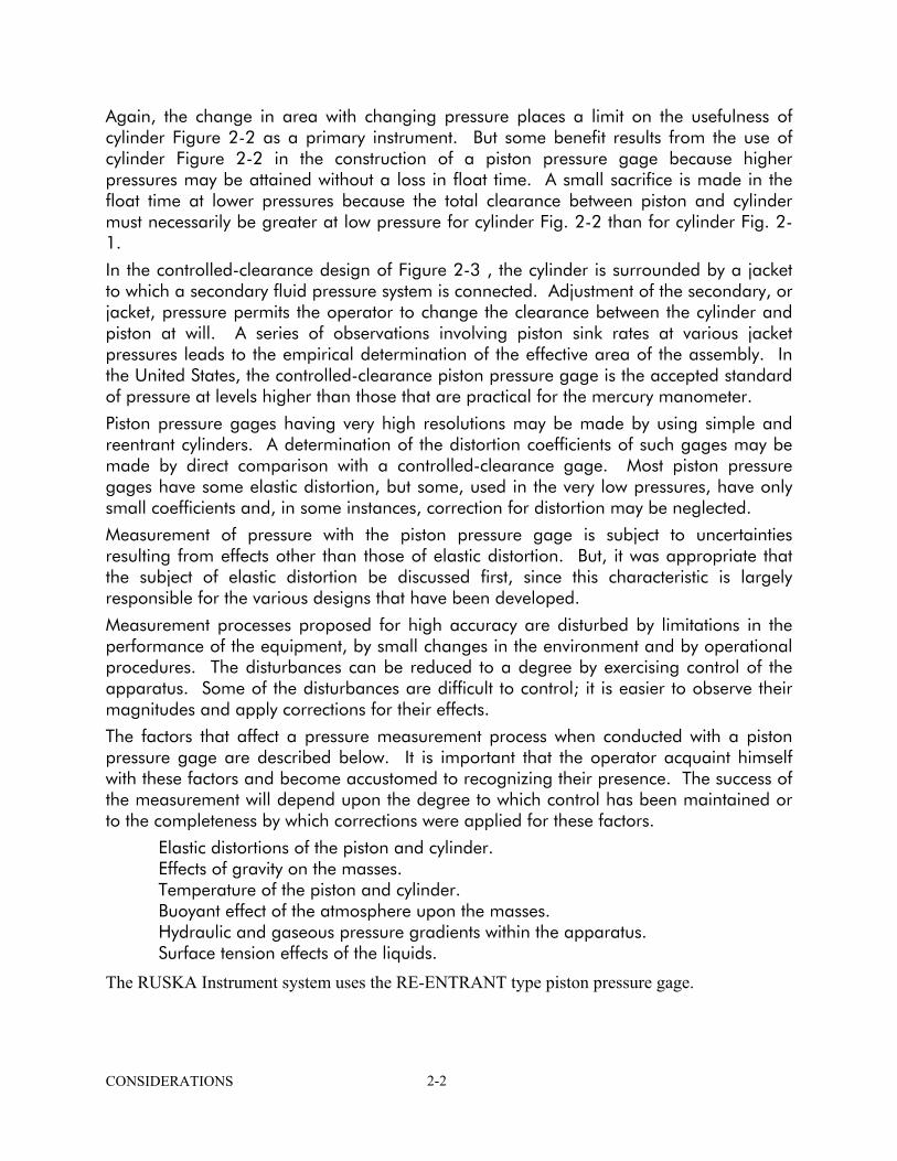
To adjust the collar on each end of the pressure tube to expose one or two threads between the collar and the cone, see Figure 4-1. Attach the tube to the gage and to the port of Valve No. 1. Move the gage to a position that will allow the gland nuts to be pulled up finger tight against the collars and that directs the tube squarely into the fitting.
Level the piston gage. The gland nuts must now be torqued to 25 foot-pounds with an appropriate wrench. The final tightening operation must be completed with the least possible residual twist stress on the tube. Several attempts may be necessary to avoid stressing the tube and causing an effect on the leveling of the piston gage. When the tube is in place, lock the level screws.
FIGURE 4-1 HIGH PRESSURE CONED AND THREADED CONNECTION
INSTALLATION 4-1

THIS PAGE INTENTIONALLY LEFT BLANK
INSTALLATION 4-2
SECTION 5.0 PRESSURIZED SYSTEMS
5.1 PRECAUTIONS
WARNING: Pressurized vessels and associated equipment are potentially dangerous. The apparatus described in this manual should be operated only by personnel trained in procedures that will assure safety to themselves, to others, and to the equipment.
The following list of precautions to be observed are distributed throughout the literature and are summarized here as a convenient source for continuous review by operating personnel. 1. Operation of equipment that is in a pressurized state must be executed in accordance
with carefully-designed procedures. The operator who violates the procedures, either by carelessness or indifference, becomes his own adversary. Absolute compliance to the conditions of cleanliness and good housekeeping must be practiced at all times.
2. The release of pressure from a system must be accomplished in such a way and at such a rate that the operator has positive control of the safety of the apparatus at any moment. If a piston gage is floating on a pressurized fluid, the pressure must not be reduced by opening a valve. The inability for the operator to throttle the valve at such a critical moment will usually result in possible damage to the piston gage. The fluid should first be withdrawn from the system with the hand pump until the piston or its weight-supporting member is resting on the thrust bearings. A vent valve may then be opened.
3. If a leak in one of the fittings or in the packing of a valve or fitting is detected while under pressure, no correction should be attempted. Release the pressure before tightening the leaking gland.
4. The process of loading the masses on the Model 2475 piston gage is critical. Consult the text for details.
5. At the conclusion of an experiment, the operator must follow the shut-down procedures and remove the pressure from all sections of the system. There are occasions when some pressure is allowed to remain within certain portions of the apparatus intentionally. A sign must be posted which advises the state of the apparatus.
6. The apparatus must be disconnected from the electrical mains whenever electrical tests or repairs are conducted.
7. During the operation of the apparatus, there will be a discharge of inert gases into the ambient atmosphere. It is mandatory that these gases be vented to the outside of the work room. Accumulation of inert gases can lead to asphyxiation. Exhaust fittings are provided at the discharge ports for the intensifier and the calibrating system for the vent conduit.
PRESSURIZED SYSTEMS 5-1
5.2 GAS-LUBRICATED PISTON PRESSURE GAGES Since its infancy, in the early 19th century, the free-piston pressure gage has benefited from the attention of many great minds. Development of design, construction materials, skills and processes, have raised the level of behavior to a state of excellence which is appropriate for use as a standard of pressure.
As the years pass, types and styles of gages change to meet the requirements of science and industry. Among those that have evaluated from these demands is the gas-lubricated piston gage. Its development has been a continuous improvement in quality as new materials and skills made their appearance. The idealistic performance of the gas-lubricated piston, however, is accompanied by unusual sources of disturbance which result in equally unusual procedures in counteraction of their effects. While the liquid-lubricated piston will operate for very long periods without concern for its cleanliness, the gas-lubricated piston requires continuous attention and service for maintaining a given performance level. The piston and cylinder must be cleaned occasionally to sustain the surface conditions and clearance within its cylinder required for the expected behavior.
A procedure for cleaning the piston-cylinder assembly is described in one of the following sections. There is no rule for estimating a satisfactory period of operation after a cleaning operation. It is suspected that the reason for the piston not remaining clean during use may be traced to the extraction properties of the gas as it passes through the system. Though a concentrated effort has been devoted to cleaning the system thoroughly, it is suspected that absorption of various vapors on the internal surfaces and extraction of the plasticizers from the packing, limit the degree of success.
5.3 PERFORMANCE OF THE MODEL 2475 PISTON PRESSURE GAGE At the present state of development, the behavior of the Ruska Model 2475 piston gage exhibits some degree of selectivity in the kinds and purity of the gases to be used in its operation. Nitrogen and argon -- two commercially available gases in relatively high purity -- have perturbing extraction properties at high pressures which appear to restrict the operation of the gage. With helium, however, the gage performs excellently, having predictable action that would be expected of this class of instrument. Helium of zero-grade purity (less than 5 ppm H2O and less than 0.5 ppm hydrocarbons) has been found to perform nicely over long periods of use.
5.4 REMOVAL OF THE PISTON-CYLINDER ASSEMBLY
CAUTION: Remove all pressure from the instrument by opening valves 5, 4, 2, and 1. Valve 3 should remain closed.
With spanner wrench, 44-618, *457), unscrew the retaining nut from the housing and lay the mass table assembly aside on a clean piece of paper. Grasp the projecting end of the piston in the jaws of the pin vise, tighten the collar, and slowly pull the piston-cylinder from the housing. As the assembly is lifted clear of the housing, hold one hand beneath it for safety reasons. If the O-ring and back-up ring cling to the cylinder, return them to the housing.
PRESSURIZED SYSTEMS 5-2
Place the piston-cylinder assembly on a pad of paper wipers with the lower end of the piston resting on the pad and the assembly tilted at an angle. Rotate the piston until both ends of the snap ring are visible. Press on the snap ring ends with the thumbnails of each hand for removal of the ring. Pressing the ring into the paper pad reduces the risk of loss during the removal process. Remove the piston from the cylinder and wrap each part in a wiper for later use.
5.5 PISTON/CYLINDER CLEANING INSTRUCTIONS 5.5.1 INTRODUCTION When it is necessary to clean the piston/cylinder assembly, the piston pressure gage must be partially disassembled and some of the components set aside until later. Upon removal of the internal components, there is the possibility of exposing the parts to harmful dirt, corrosive fingerprints, or dropping parts. The small, brittle, carbide measuring piston is not likely to survive an accidental drop. The remainder of the components, if dropped, may be damaged to the extent of sustaining raised burrs and will require the attention of a mechanic before reassembly.
Each manual operation that is performed on a mechanical device is accompanied by a finite degree of damage. The damage, however small for the individual operations, is cumulative and results from the imperfect execution of each manual operation. After a given period of time, the device may be expected to fail because of performance deterioration beyond the level of tolerance. It is important, therefore, to perform these tasks with the greatest possible skill in order to hold the cumulative effects to a minimum.
There are two types of contamination that affect, not only the performance of a piston pressure gage, but the physical state of the critical components as well. One contaminant is the ordinary hard particle of matter that scratches and abrades the finely-finished surfaces as it becomes entrapped between the closely-fitting members. The scratches invariably result in raised edges from the displacement of the metal and spoil the original relationship of the members. The second type of contaminant is of a chemical nature and produces harmful effects by attacking the finished metallic surfaces in a corrosive manner. Ordinary fingerprints contain water-soluble, acidic salts, having extremely high corrosive activity with the metals of the critical instrument parts. Since these parts must necessarily be handled in making a piston exchange, they may be protected from exposure to both types of contaminants by the use of clean insulating paper wipers.
There are a number of industrial paper wipers available that are relatively free of lint. After a little practice, the corrosion-sensitive parts may be handled safely with these wipers instead of bare fingers. Even when using the wipers as insulators, the hands should first be washed and thoroughly dried before beginning the disassembly.
CAUTION: REMOVE ALL PRESSURE FROM THE PISTON PRESSURE GAGE BY VENTING THE PRESSURE HOUSING TO THE ATMOSPHERE.
PRESSURIZED SYSTEMS 5-3
5.5.2 CLEANING WITH ORGANIC SOLVENTS There are two basic cleaning methods for the piston/cylinder. Both methods will be described below. The first method uses soap and water and is the method which has achieved the greatest degree of success in the Ruska laboratories. The soap does contain organic compounds and therefore must be thoroughly rinsed away to prevent contamination of the piston/cylinder. The other cleaning method uses trichlorotrifluoroethane (du Pont Freon TF or Freon 113), hereafter called TF for convenience and 190 proof ethyl alcohol. TF is being more and more strictly regulated because of its ozone depletion characteristics and eventually will no longer be allowed as a cleaning agent. Replacements for TF are being formulated but have not yet been evaluated for use in this particular application. The ethyl alcohol is flammable and must not be introduced into the calibration system.
5.5.3 CLEANING PROCEDURE USING SOAP AND WATER Cleaning supplies for the piston/cylinder consist of: 1. Kimwipes, Kimberly-Clark Type 34150. 2. Hand Soap (Cashmere Bouquet). 3. Cleaning Brush 4. Paper Towels (Shur-Wipes No. 298-1) 5. Du Pont Freon TF (trichlorotrifluoroethane) A clean space should be prepared on a work bench. Cover this space with paper towels so that cleaned parts will not be contaminated. Disassemble the piston cylinder subassembly. The Snap Ring (2460-6-155) can be removed from the piston by placing the snap ring end of the piston on a table and pushing on one side of the Snap Ring with the Snap Ring Applicator (2-774) while holding the other side of the Snap Ring with a fingernail. Remove the Snap Ring carefully, because it has a tendency to "snap" off the piston and become lost. The Snap Ring is part of the tare mass and should only be replaced by one with the same mass. The operator should wash his hands thoroughly to remove all traces of oils. This precaution will prevent contaminates from being transmitted to the piston and cylinder or to the Kimwipes which will be used to dry the cylinder. Prepare three Kimwipes for drying the cylinder bore by grasping diagonal corners and twisting. Place these three Kimwipes on the paper towel covered work bench and cover with a paper towel. Wash the outside of the cylinder with soap, a paper towel, and hot running water (110-120 degrees F). Rinse thoroughly in hot water. Wash the inside of the cylinder thoroughly with the cleaning brush, soap, and hot water. Wash and rinse the cylinder bore three times. Working rapidly to prevent the formation of water spots, dry the outside of the cylinder with a paper towel and immediately pull the twisted Kimwipes (which were previously prepared) partially through the bore of the cylinder. Before pulling the Kimwipe back out of the bore, tear off the twisted end which was put through the bore. Pulling the torn end through the cylinder last will prevent any finger oils on the Kimwipe from contaminating
PRESSURIZED SYSTEMS 5-4
the bore. Set the cylinder on the paper towel covered work bench and cover with a clean Kimwipe. Thoroughly wash the piston with soap, a paper towel, and hot running water. Wash and rinse the piston three times. During washing, run a fingernail, covered by the paper towel, around the snap ring groove. Immediately after the final through rinsing, dry the piston with a clean paper towel. Rub the piston with several different dry portions of the towel to insure complete drying. Pay particular attention to the snap ring groove and to the joint of the piston and weight table. Set the piston on the paper towel covered work bench and cover with a Kimwipe for 5 to 10 minutes to cool.
5.5.4 CLEANING PROCEDURE USING FREON AND ALCOHOL Cleaning supplies consist of small laboratory-type dispensing bottles, one containing TF, and the other, 190 proof ethyl alcohol. A supply of medical-quality applicators (Puritan No. 807-12), 15 cm length by 2mm dia, sterile absorbent cotton, large industrial wipers or paper towels, smaller wipers for cleaning the piston (Kimberly Clark Kimwipes No. 34155), 11.5 x 20.3 cm, and a pin vise, will also be necessary. Trade name shave been given because of the preference of these materials by those who have used them; other brands may serve as well.
The TF is an excellent degreasing agent, nontoxic, inactive with oxygen, but is a poor solvent for water-soluble salts. Inorganic salts and acids that are components of fingerprints and airborne substances, are not easily removed with TF. Alcohol, on the other hand, is an effective solvent for the water-soluble components of surface soil but is not a strong degreasing agent. It is desirable, therefore, to use each of the solvents for removal of both types of surface deposits. Which of them is used first may be of a matter of choice but there is a possibility that the oil component of surface contamination may have a greater masking action on the water soluble compounds than vice versa. Satisfactory performance has been achieved when the oil solvent, TF, was used initially and followed by alcohol.
The work area for the cleaning process should itself be clean and free of clutter. A clean table or workbench at which one can sit, comfortably, is desired. Wind drafts which might carry dust and fumes should be directed away from the area.
The following instructions will be given in command form for simplification of the text and for better identification of the individual operations.
Wash the table working area with soap and water, dry thoroughly and cover the area before the operator with two or three clean paper towels. Wash and dry the hands before beginning the process. After washing with water, a wad of a small wiper, moist with TF, can be used for wiping the ends of the thumbs and forefingers for removal of residual oils. The cylinder may then be handled with the bare fingers without affecting the process and the task of folding the paper wipers for cleaning the piston will be simplified. If the operator is susceptible to dermatitis or discomfort form the temporary loss of finger oils, the use of latex surgical gloves may be necessary.
PRESSURIZED SYSTEMS 5-5
1. Fold twelve or more Kimwipes into pads of one each., approximately 6 cm on a side. Three folds, reducing the sheet size to one-half each, will result in eight thicknesses of material that will offer good absorption qualities for the solvent and resistance to penetration of finger oils. Since availability of the pads at a critical moment of the operation is important to success, there should be ample quantity. Cover the pads with an open wiper and set them aside for later use.
2. The cylinder will be cleaned first so that it may be stabilizing in temperature as the piston is being cleaned. With a wad of Kimwipe, soaked with TF, clean the outside of the cylinder for removal of grease deposits. Once clean and dry, the cylinder may be handled with the tips of bare fingers without harm.
Remove a skein of cotton of 20 to 30 cm length from the side of the roll rather than from the end. Wrap the skein loosely with one of the large wipers such that one end of the cotton is available. If the cotton is removed from the end of the roll, many of the fibers will be broken and will wrap poorly onto the end of an applicator.
3. Some experimenting and practice will probably be required for twisting a neat, tapering wad of cotton on the end of an applicator for use as a swab. The finished diameter of the swab is important since it must enter the bore of the cylinder with substantial friction but must yet be controllable. Removal of the surface films is considered to be more of a mechanical process than of a chemical one.
Insert the swab into the bore of the cylinder and apply TF until it is wet. Stroke the swab within the cylinder ten times while twisting it in the direction as to keep the cotton tight on the shaft. Repeat the cycle twice more and with the last cycle, clean both faces of the cylinder with the swab.
4. In identical manner, wash the cylinder bore with alcohol as the solvent. For the third cycle with alcohol, the swab should not be saturated with the liquid. If the swab is wetted, with a quick fling-like motion of the arm and wrist, most of the liquid will be thrown out of the cotton. With this type of swab, the cylinder will be dried more easily.
5. Twist another swab of dry cotton from the skein and tighten the wad on the applicator by turning it against one of the wipers on the table surface. The wad must not be tightened with the fingers as oil would be transferred to the cotton. Force the dry swab into the bore in the same manner as before while maintaining a twisting and stroking motion. To be effective, the action should require considerable force. Repeat the drying operation as the final step in cleaning the cylinder. Lay the cylinder aside and cover it with a wiper. Of the several sizes of bamboo skewers available from grocery markets, some are small enough to be used for cleaning the cylinder. The skewers are much stronger than the applicators and may be preferred.
The piston is somewhat more difficult to clean since it must be held by the wiper pads at all times; the fingers must not be allowed to touch the surface. Pick the piston up by one end in the fold of a pad. Soak a second pad with TF and fold it over the opposite end. Stroke the free end of the piston ten times while extending the stroke past the center as far as possible; press the pad firmly against the surface to produce friction in the action.
PRESSURIZED SYSTEMS 5-6
Reverse the piston and pads in the hands and repeat the operation on the opposite end. The groove in which the snap ring is placed is a trap for the contaminants; it can be cleaned by forcing a wiper into the narrow space with a fingernail while rotating the piston with the opposite hand.
The complete operation requires two cycles while using TF, two with alcohol and two with dry wipers. When working with alcohol, the pads should not be dripping wet with the solvent. Alcohol is hygroscopic and its affinity for water will disturb the process if the proper precautions are not heeded. Absorption of moisture from the atmosphere will dilute the alcohol to the extent that its action as a solvent and its rate of evaporation will decrease. At least for the second cycle, the operator must work quickly with a pad only slightly wet with the liquid; moreover, the container must be tightly capped when not in use.
Rub the piston briskly with two dry pads. With some experience, the operator will become familiar with the characteristic drag of the drying pad against the piston as the stroking action nears completion. The "feel" of the drag is sometimes regarded as an indicator of the success of the cleaning operation.
5.5.5 REASSEMBLY OF THE PISTON AND CYLINDER While waiting for the piston and cylinder to cool, clean the snap ring, and face seal with Freon-TF (trichlorotrifluoroethane) cleaning solvent or with ehtyl alcohol.
After inserting the snap-ring in the tool, install the ring on the piston. Be certain that the snap ring is completely inserted in its groove so that the piston is securely retained in the cylinder when assembled. The snap ring can be manipulated into the tool by forcing the ring against the end of an applicator that is held firmly to one of the wipers on the table.
Pick the piston up in the fold of a doubled Kimwipe and insert it into the cylinder with the snap-ring at the face of the small neck as illustrated in Figure 3-2. Remove it and insert it the second time for removal of lint which might cling to the surface.
Complete freedom of the piston within the cylinder must be achieved before the assembly can be used. If there appears to be any resistance to motion of the piston after insertion to the cylinder, it must be determined that the piston is either not yet clean or that there is a speck of lint or dust entrapped within the annulus. If the assembly is held in one hand in an inverted attitude, the piston may be pushed from beneath with a paper-wrapped finger and allowed to fall freely against the snap ring. The snap ring must strike the end of the cylinder with a force that would indicate full freedom -- that the piston were falling through a very large bore. This quick action will usually clear out anything in the bore that would offer resistance. If the assembly passes this test, it may be placed in the pressure housing for operation.
Clean the seal and back-up ring and return them to the position in housing as shown in Figure 3-2. Insert the piston-cylinder assembly while grasping the upper end of the piston with the pin vise or with a folded wiper pad.
Replace the mass loading table assembly and tighten the retaining cap with the pin-spanner wrench while using only moderate torquing force. The loading table itself will
PRESSURIZED SYSTEMS 5-7

be observed to tilt slightly to the side because it is being lifted by the spring-loaded plunger beneath the piston. The purpose of the spring load is to center the loading table support directly over the piston.
5.6 PRELIMINARY TEST PROCEDURES Having placed the instrument in its permanent location, the succeeding task is a test of the system for leaks and performance. Operating procedures must be practiced carefully and repeatedly for acquiring the skill and attention that is demanded for the safety in its use. Indeed, in the organization of policies, procedures and schedules, the most important, and of the highest priority, is the subject of safety. Written policies and procedures must begin with, and continue to reiterate, statements of mandatory obedience to safe operating practices.
Safety begins with the operator's respect for the apparatus -- for its value, its capability, appearance and, most importantly, for its hazardous potential. Every opportunity has been exploited in reducing the internal volume of the system in order to minimize the danger -- the smaller the volume of compressed gas, the less the degree of hazard. Much expert craftsmanship and toil has gone into the construction of a device that performs its function well. Its visual appearance is manifestation of the care with which it was produced. The equipment is designed for many years of useful service; only good housekeeping practices and correct operation will keep it so.
Of primary concern, is the operator's attitude toward the care of the valves. The act of closing a valve involves a substantial degree of judgment, particularly for needle valves. Most needle valves are designed such that eh cone of the hard stem forms its seat when being forced into the aperture of the body. The condition for a seal is that in which the pressure within the seat is only slightly greater than that of the fluid being sealed. The concept is sound except that careless closure of the stem with excessive torque can enlarge the seat and thus the area of contact. Thereafter, the stem must be torqued to that same value to achieve the correct seat pressure. The problem is compounded by the fact that, at high pressures, the axial thrust on the stem against the threads of the spindle and additional friction from compressed packing, increases the torque to a value which can equal or exceed the sealing torque. Moreover, some operators are unaware of their own strength and can damage a valve seriously from excessive torque without realizing it. Carelessness of, or indifference to, this dilemma can cause early failure of a valve.
The operator should study the construction of the valve, the diameter of the stem and its function in the system. Torquing the valve at atmospheric pressure should also be practiced. Only practice and experience will acquaint the operator with the correct torquing action. In a manner of speaking, he is calibrating his senses and is accumulating valuable experience.
In the interest of safety, a policy for the use of vales should be adopted as a standard operating procedure. There are two functions for the valves used in the Ruska Model 2475-610 Calibrating System:
Valves through which the measuring gas passes Throttling or supply valves
PRESSURIZED SYSTEMS 5-8
When the system is in use, the measuring valves must be opened fully for allowing the gas to pass freely. The valve should be opened fully, (counterclockwise rotation) and then closed (clockwise) one half-turn of the stem. In this position, the stem is not restrained in either direction of rotation and the operator can determine the position of the valve with a slight turn of the stem in either direction. He then knows the valve is open. If the stem is fully opened against the back stop, the operator may not remember the status of operation and can become confused as to what action to take.
For efficient operation, the supply valves need to be opened no more than one and one-half turns. Throttling valves present a disturbing inconvenience. If the backlash in the non-rotating stem is excessive, the lag in the action of the stem from rotation of the spindle will cause some frustration. In an attempt to open a valve slowly, the stem action will lag behind the rotation until the backlash is taken up, then, a slight motion of the stem will release the static friction of the packing and the pressure will force the stem back against the clearance of the adjustment. The result is a surge of gas that is greater than expected. The backlash should be kept minimum at all times. Adjusting nuts are accessible on the stem after removal of the handle.
Though the Ruska Model 2475-610 Pressure Calibrating System was tested at the factory for pressure integrity and for the absence of leaks, the partial disassembly, the disturbance of crating and shipping may have caused leaks to reappear. It is worth while to test the system for leaks before attempting responsible work. In the process of leak testing, the operator will become acquainted with the operating procedures and will be better prepared for serious work.
The piston gage is an excellent leak detector by virtue of its predictable sink rate. If a leak exists in the system, its approximate location can be found through a systematic search by isolation of various portions of the system. The magnitude of the leak can also be estimated.
Directions for operation of the system will be less detailed for the leak test than for the calibration of a test gage. The operator is encouraged to read the entire instructions before beginning the tests.
The piston gage was shipped with a freshly-cleaned piston assembled to the pressure housing. It is probable that the piston will have remained clean during shipment and installation of the equipment. Testing instructions that follow will be similar to operations 1 through 20 of the test calibration procedures (see pages 5-10 and 5-11). The differences in the two processes is sufficient to cause confusion if one is described in terms of the other. At the risk of creating annoying repetition, individual instructions will be given for each process.
With fresh bottles of helium and nitrogen connected to the apparatus and secured with the chains, proceed:
SYSTEM TESTS FOR LEAKS A preliminary system leak test will be conducted with the piston gage isolated. Valve 1 must be closed. Though the test is inadequate for a final status assessment, it is worthwhile for safety reasons and for helping the operator to become acquainted with
PRESSURIZED SYSTEMS 5-9
the valve actions and general operating procedures. Instructions are given as commands. The numbers in the body of the text refer to the valves (see Figure 3-3).
With nitrogen and helium bottles connected and secured with chains:
1. Plug the test port in the block-connector 2424-800. The plug is Ruska P/N 25-47 (Autoclave AP60).
2. Open valves 2, 4, 5, and 6. This operation opens the main system to the atmosphere.
3. Set the pump plunger at approximate mid-stroke.
4. Close 1, 2, 3, 5, 7, 8, and 9.
5. Open both gas bottles slowly and fully. Nitrogen gas pressure will be delivered to valve 8 and helium to 9. Usually bottle valve stems can be back-seated. If the valve is opened fully and hard against the back seat, the possibility of gas loss through a bad or worn stem packing is reduced. Place the intensifier manifold switch in the "ON" position.
6. Open 9 slowly. Helium will be admitted to the system; it will pass through the intensifier unimpeded, until the supply system, to 3, is at bottle pressure. As the helium passes through the check valves of the intensifier, the gas flow will produce an audible sound as the poppets are activated. This "song" is a useful signal to the operator as valve 9 is being adjusted. As the helium supply pressure builds up ahead of 3, the pressure gage at Block/gage Assembly, 2424-802, will indicate that of the bottle. The helium pressure also drives the intensifier piston to its position which is ready for a compression stroke. This condition is indicated by illumination of the "DOWN" pilot light. A minute or so pause in the procedure will allow the gas to stabilize partially and will indicate any gross leaks in the supply portion of the system. If no large leaks are detected, go to step 7.
7. Open 3 slowly. This operation adds the hand pump to the supply system.
8. Open 2 slowly. With the exception of the piston gage, the entire system is now pressurized with helium to bottle pressure. Large leaks at bottle pressure are not expected but may occur from unpredicted handling or other causes.
9. Open 8. The nitrogen will be admitted to 7. Valve 8 may be used for throttling the nitrogen to the intensifier for vernier control of the increasing pressure when it is convenient. (More of this will be covered later.).
10. Open 7 slowly. Here the word "slowly" is indefinite but can be modified to suit the operator as experience is accumulated. The nitrogen pressure will intensify the helium as will be observed on both Bourdon pressure gages. When the intensifier piston completes its compression stroke, the gages will stop rising. Do not allow the nitrogen to continue flowing through 7 because no additional benefit will be gained. The additional nitrogen is not only wasted but the chances that the driving pressure will be increased to the relief valve limit with release and a disturbing report. A second indication of completion of the compression stroke is the illumination of the
PRESSURIZED SYSTEMS 5-10
"UP" pilot light; the third is a characteristic sound of the intensifier piston striking the internal stop at the end of its stroke. In general, the sounds emitted by the intensifier during its use serve to advise the operator of the changing conditions without drawing his eyes away from the important visual activities of the process.
11. Open 6 partially at first, then more fully as the nitrogen pressure is exhausted from the intensifier. The helium bottle pressure will again drive the piston to its "DOWN" position (when the intensifier is mounted vertically, as is sometimes the occasion, the words "UP" and "DOWN" refer to positions of the piston as "for intake stroke" and "for compression stroke", respectively). Again, the characteristic sounds may sometimes be substituted for visual signals for the momentary status.
12. Close 6 and open 7 for a second stroke.
13. Repeat operations 10 through 12 as required to continue increasing system pressure. It will be observed that, as the pressure rises, the increment diminishes with each stroke; moreover, the increase of pressure gage indication lags behind the action of the intensifier more and more with greater pressure. The reason is that the pressure above the advancing piston must become equal to the existing system pressure before the helium can be forced through the output check valve. Unfortunately, there are no visual or audible signals that indicate the progress of the advancing piston. If the nitrogen bottle pressure drops below the critical limit, for instance, the intensifier piston will stop moving and there will be no signal that indicates such has occurred. After a few such occasions, the operator will recognize the conditions and will make advance preparations for corrections. At the higher pressures, it is well to start the compression with the hand pump plunger fully withdrawn. If the intensifier fails to deliver the required pressure, for whatever reason, the hand pump may be used to increase system pressure by almost 2000 psi. Sometimes this maneuver will save time at the end of a calibration cycle.
14. Increase the pressure to 15,000 psi, as indicated by the dial gages and close 3. Allow the pressure to dwell for 10 minutes then boost it back to maximum for a period of 10 additional minutes. No limit on the pressure drop that occurs the second 10-minute period can be given reliably but if the system appears reasonably stable, the final test may be conducted.
15. Close 8 and 9; open 3 and 5 slowly, then 6 and 1 slowly. The entire system should be at atmospheric pressure; to be certain, check that 1 through 7 are open. If it is likely that there will be delay in progressing tot he following tests, close the bottle valves and open 8 and 9. The system should be free of all pressurized gas.
FINAL SYSTEM PERFORMANCE TEST For this test, a clean piston-cylinder assembly must be installed in the gage.
The following instructions describe the procedure for loading, pressurizing, and assessing the performance of the pressure measurement system. With the piston gage floating at maximum pressure, the system leakage may be estimated from the characteristic sink rate of the piston. Sink rates are determined by observing the falling masses for a period of time over a measured distance. A scale is placed near the lower edge of the mass
PRESSURIZED SYSTEMS 5-11
stack and an interval of distance is timed with a stopwatch. A more accurate value is obtained when the AutoPrompt Converter is used. With that instrument, the displayed sink rate is a part of its algorithm. Sink-rage measurements are trustworthy, however, only when the pressurized medium is truly static, i.e., when there is no leakage and when the fluid is thermally stable. When consecutive measurements are consistent and agree with that reported by the manufacturer, the medium is stable and the system leakage, if any, is acceptable. As the loading and pressurizing process is conducted, an assessment of the piston cleanliness and expected performance can be made. Proceed as follows:
1. With the test port in the 2424-800 connector block plugged, open 5,4,2,1, and 6 in that order.
2. Place the hand pump plunger at approximate mid-stroke.
3. Close 2, 3, 5, 7, 8, and 9.
4. Open both gas bottles slowly and fully.
5. Confirm that 3 is closed and open 9 slightly and momentarily to allow only a small quantity of helium to pass. The intent is to create a small differential of pressure across 3 so that the gas can be throttled into the system at low pressure with good control.
6. While wearing protective gloves, place the number 1 sleeve mass (hanger) on the loading table of the piston gage. The force of the number 1 mass should seat the table assembly firmly against the lower thrust bearing. Test the action by pressing down slightly on the table top surface; there should be no movement.
7. Place a gloved hand on the table as a damper against accidental overpressure from the following action. The piston table assembly and sleeve will rise at an internal pressure of approximately 170 psi (1.2 MPa) which is the tare pressure of the gage. Open 3 slowly and momentarily to allow a quantity of helium to pass through; such low pressure will not register on either of the Bourdon tube gages. If the sleeve does not float up when the hand load is reduced, lift the assembly and test the lifting force as a measure of the action; add more gas, if necessary. If the assembly floats to the top limiting stop, withdrawal of the pump plunger may drop the piston to the lower stop. With the load resting in the down position, rotate the sleeve and advance the pump plunger. At the correct pressure, the sleeve should rise to float very smoothly with no indication of hesitation or of a jerky motion. When floating it should appear to bounce in response to the slightest disturbance. This type of activity is a strong indication that the piston is clean and ready to function as expected.
8. Withdraw the pump plunger sufficiently to drop the floating piston to its lower stop. Place the number 2 disk on the sleeve with the sequence number, 02, in alignment with the -01 number of the sleeve. Alignment of the sequence numbers will be of value when counting and verifying the masses for each load; it is good practice. When loading a disk, the operator should concentrate on the act of guiding it
PRESSURIZED SYSTEMS 5-12
carefully over the sleeve to avoid scraping the surface of the latter. Such carelessness will quickly spoil the finish and affect its mass.
9. In the same manner, apply disks 03 through 06 for a total of 26 kg (5 disks plus sleeve). This load represents a nominal internal pressure of 4410 psi (30.4 MPa).
10. Open 9 and allow helium bottle pressure to 3 as indicated by the Bourdon gage at the rear of the table. Open 3 slowly and admit the pressure to the system. The hand pump gage will register the same pressure as the rear gage.
Valves 7 and 8 perform the same function but with different degrees of convenience. When there is little danger of perilous consequences, 8 may be opened fully and 7 used for rapid activation of the intensifier as a convenient time-saver. As the internal system pressure approaches the piston gage float pressure, however, valve 8 becomes much safer in throttling the rate of pressure increase. When 8 is used for controlling approaching pressures, 7 must be open. Ideally, the pressure is adjusted to a value slightly less than the final one and adjustment is then transferred to the hand pump. Because of the coarseness of the gage indication, there is a possibility of overshooting the intended value. Until a degree of skill is achieved from practice, it is wise to protect the piston from overpressure shock with the force of a gloved hand.
If the first stoke of the intensifier is insufficient to float the piston, a second one will be necessary. See operation 11, Page 5-9, for the procedure.
11. Close 3 and adjust the pressure with the hand pump for floating the piston. At this time, the entire system is in a state of shock. Several minutes will be required for it to recover. The gas, after having been heated from the compression action, will give its heat to the apparatus and, in doing so, will contract to a smaller volume. If the gage piston is floating, however, the loss of heat will not be manifested as a loss in pressure but as an increase in sink rate of the piston. While the piston is floating, it maintains the pressure throughout its float range. Since the measurement of the sink rate is the objective, the stabilization of the gas must be allowed to go to completion. Set the mass load in rotation by turning the sleeve near its top. Rotation forces applied near the sleeve top will cause the least disturbance to the stability of the stack.
12. After a recovery period of 4 to 5 minutes, raise the piston to near the top of its stroke and close 1. Observe the scribed index line on the pressure housing by using the mirror attachment. Begin measuring the descent rate from some chosen point with a stop watch. In the beginning, it matters little if the starting point is near the top of the float position or if it is in the center. The final observation, however, must be observed through the designated floating range near the center of the stroke. Repeated observations must be made until the values are consistent; only then is the observed value dependable. A repeatable number is an indication that the gas within the gage is stable.
Observe the freedom of the piston and the general response to slight disturbances while it is floating. A light touch of the finger to the top of the sleeve should set up
PRESSURIZED SYSTEMS 5-13
an oscillation of the load of several cycles. If the sink rate is within specifications proceed to the next operation. If the rate exceeds the specifications, there may be a gas leak at the cylinder seal or at one of the two connections between the piston gage pressure housing and valve 1.
13. Press the load stack down against the lower thrust bearing and hold it there while opening 1. If the system pressure has diminished during the previous test, this action will avoid allowing the piston and its load to fall.
14. Readjust the pressure to float the piston and repeat the observations of operation 12 for the system leak test.
15. Load the remainder of the disks to the piston gage, in sequence and with numbers aligned. Review the status of the valves for pressurizing the system to 15,000 PSI (103.4 MPa).
5 and 7 ( or 8 ) - closed 1, 2, 3, 4, 6, and 9 - open
16. Begin building up the system pressure by cycling the intensifier as described in operations 9, 10 and 11 of the Leak Test Procedures, Page 5-9. Fortunately, the gas at 15,000 PSI is so dense that small changes in volume of the system create rather large changes in pressure. The Bourdon gages at this pressure are quite useful.
The intensifier can be controlled without great risk to an output of somewhat greater than 14,000 PSI. Adjustment of the hand pump may then be used to raise the pressure to final value. Again, the piston should rise (after manual rotation of the stack) smoothly and deliberately.
17. After 5 to 10 minutes dwell, raise the piston to the top of the stroke and close 1.
18. Measure the sink rate as in Operation 12 above. Make a note of the rate for comparison with that of the next operation.
19. Press the floating stack down and hold it while opening 1. Readjust the piston to float and measure the sink rate of the entire system. Close valve 2 while making this measurement. When the observed rate is uniform for successive trails, within the limits of the observation process, compare the new rate with that of operation 18 above. If the difference is substantial, a leak is probable in the portion of the system being tested. Its location may be found by closing 4 and measuring the rate. Leaks are likely to occur in the valve g because these seals are disturbed repeatedly.
20. When the performance is acceptable, shut the system down as described in Operation 15, page 5-10, of "System Test for Leaks". Double check the bottle valves and zero pressure on the bottle gages before securing the apparatus.
5.7 CARE AND HANDLING OF THE MASSES It is customary to handle the masses with cotton or nylon gloves for protection of the surface against salty and acidic hand prints. Not only does the practice preserve the surfaces, and the appearance, but it keeps the operator aware of the value of, and his
PRESSURIZED SYSTEMS 5-14
dependence upon, the instrument. Discipline in the manner of handling the masses reinforces the demands for continuous carefulness when used.
Application of the masses to the piston gage requires a degree of skill. Careless handling can result in shock to the piston and damage to the finish of the masses. One clue to a successful loading operation is the audible sound that is generated in its execution. A casual manner of dragging the applied ring mass along the outside surface of the hanger sleeve, or of guiding it into its nest inaccurately, is a sound-producing action. The operator should regard these sounds as signals of ominous protest from the apparatus. When it is observed, and felt, physically, that the nest is engaged, the load must be transferred to the stock gradually.
Since the loading operation is associated with, and dependent on, manipulation of the pressure, details of the individual operations are described in the section on preliminary testing of the apparatus. In that section, the sequence of loading and testing is described without having discontinuities.
5.8 CALIBRATION OF ELASTIC SENSOR A procedure is described in which the test gage is calibrated in increasing and decreasing sequence for measurement of hysteresis effects. It is assumed that written procedures or policy do not permit the test pressure to act in retrograde when changing from one level to the successive one. It is also assumed that the policy includes proof test and exercise of the sensing element before the calibration is begun. If exercise is not required, at least one cycle of full scale pressure should be applied to the test gage for reasons of safety. The device being calibrated will be referred to as the test gage. The test gage should be exposed to maximum pressure for certainty that the sensing element will not burst and expose the piston gage to shock.
Mount the test gage at the connector block, Ruska Model 2424-800. If the instrument is too large to be supported by the connecting nipple, a stand with the appropriate piping may be necessary.
5.8.1 OPERATION The first operation will be that of proof testing the sensing element for strength and exercising it through two cycles of full-scale pressure. With a clean piston installed in the gage, values of mass calculated for all pressure test gage calibration points, adequate supply of nitrogen and helium connected for service, proceed as directed by the following operations.
5.8.1.1 Increasing Pressures 1. Close valves 1, 7, 8 and 9. 2. Open 2, 3, 4, 5 and 6. 3. Set the test gage to zero indication. If the test gage contains electronics, allow
the unit to warm up for the prescribed time. Advance the hand pump plunger to within 1 cm of full forward position (clockwise rotation of the turnstile).
4. Close 5. 5. Open both the gas bottles.
PRESSURIZED SYSTEMS 5-15

6. Open 9 slowly. The helium will be admitted to the system; it will pass through the intensifier, unimpeded, until the system pressure gage indicates bottle pressure. There is little reason for the hand pump to be used in this operation. If the plunger of the hand pump is in the forward position, almost its entire length, the internal volume of the pump will be reduced significantly and helium will be saved.
7. Close 6; open 8 then 7, slowly. Compression of the helium will begin as the nitrogen forces the intensifier piston in the upward direction (compression stroke).
8. Observe the hand pump gage. When the pointer stops moving close 7. 9. Open 6 and discharge the nitrogen.
10. When the nitrogen ceases to flow, the intensifier piston can be heard to stop against the end cap with an audible impact. Close 6.
11. Repeat operations 7 through 10, opening and closing the respective valves alternately until the pressure is at the maximum of the test gage. Allow the pressure to dwell for, at least, 3 minutes. The pressure will decrease somewhat form the loss of its compression heat.
12. Close 2 and discharge the gas in the system through 5. Allow the test gage to recover for whatever period of time specified in the written procedures for calibration. Reset the zero if required.
13. Close 5, open 2, and repeat operations 7 through 12 for the second exercise cycle. The two exercise cycles also satisfy the proof-test requirements.
14. With 5 open, release the accumulated pressure in the system through 2 from the intensifier. Valve 3 should be closed when the pressure is reduced to that of the bottle.
15. Reset the zero of the test gage, carefully, as the starting point of the calibration.
16. Withdraw the plunger to within approximately 1 cm of the starting position.
17. Load the piston gage with masses calculated for the first calibration pressure. If the AutoPrompt Converter is being used, the display will list the masses required. In the absence of the converter, see Appendix A for calculation instructions.
18. For those specified pressures that are less than that of the bottle, the practice of accumulating gas between valves 3 and 9 may be of benefit. The objective is to reduce the differential across 3 for better control of the input pressure. The system pressure should be adjusted to a value slightly less than the calibration point and then control assumed with the hand pump.
19. Close 3 and jog 9 quickly to admit a quantity of helium to vale 3; this action will become more effective after having a little practice on the table.
20. Open 3 slowly while observing the output of the test gage. This gage is likely to be more sensitive than the hand pump gage when working at low pressures. Stop the input at a pressure less than the specified value.
PRESSURIZED SYSTEMS 5-16
21. Start the rotation of the masses.
22. the piston must be brought to float by the action of the hand pump. Advance the hand pump plunger slowly and steadily until the masses begin to rise. With a smooth action of the pump, raise the piston and its load to a position will above the float position index line.
23. For this type of calibration, the increments of pressure change are relatively small. The pressure should stabilize within 3 to 4 minutes. It is advisable to keep the piston floating during the stabilizing period. After sufficient time has elapsed, the piston is carefully raised to a position of 2 to 3 mm above the index line. The adjustment does not change the pressure but does disturb the distribution of gas within the system. As the piston begins to sink into the correct float position, as identified by the index line, the disturbance has adequate time to equilibrate. When the sinking masses pass the index line, the moment for measurement is correct. The indication of the test gage is observed and recorded with the temperature of the piston gage and the time of observation. Hysteresis effects are time-related. If the policy requires dual observations, dither the test gage, observe and record the second displayed value.
24. In preparation for the exchange of masses for the succeeding pressure point, the action of the piston must be considered. If it is the policy to prevent the pressure in the test gage from dropping below the previous observed value, some measure of control must be exercised. When the load for the succeeding pressure requires only the addition of more mass rather than the substitution of some for others, there is not a problem. The additional masses may be loaded directly and the operation continued. This situation is the exception rather than the rule. Normally, one or more of the masses must be exchanged for others. In making the exchange, one mass must be removed and replaced by another. When one is removed, the piston will rise and, in doing so, its pumping action will allow the pressure to decrease. The rule prohibiting retrograde pressure is violated. One method of preventing a reduction in pressure is to close 4 and retain that which is in the test gage while the piston gage is being changed. After increasing (or decreasing) the pressure from its previous valve, valve 4 may then be opened slowly. This procedure is time consuming, injurious to the valve and annoying to the operator. It is, however, relatively risk free.
A second procedure involves the use of the upper limiting stop of the piston. In the increasing sequence and, after a calibration point is observed, the pressure is increased until the piston is arrested in its movement by the upper stop. After a small additional increase in pressure, the leakage of the gas past the piston will not be sufficient to allow the pressure to drop during the exchange of masses.
With the piston holding the load firmly in the full "up" position, the masses may be exchanged. Usually, one or more of the masses previously loaded on the
PRESSURIZED SYSTEMS 5-17
piston must be removed and substituted by a large one. Though this procedure is more convenient and rapid than that of closing 4, it is not without risk. The piston is extended to its fullest limit from the cylinder and is in its most vulnerable position. If the masses are loaded carelessly, while the piston is extended, there is a possibility of damage.
The alternative, of course, is to reduce the pressure, after an observation, to a value below that at which the piston will rise upon the removal of the mass which is to be substituted. The hazard to the extended piston is avoided but only on the ascending or increasing sequence of operations. The practice also violates the no-retrograde pressure rule.
25. Assuming the choice is to use the upper limiting stop, the piston is raised to its upper limit and the masses for the succeeding pressure value are exchanged. Since the new load is greater than before, one of those added will force the piston downward to the lower stop. This action must be anticipated and the placement for the mass, over the sleeve hanger and onto its nest, must be executed with extreme care. As the mass is allowed to transfer its force to the nest, allowance for the action must be slow and deliberate. The success of this operation may be judged by the audible sound that is generated. This impact should be so slight as to produce very little sound.
26. Having exchanged the masses by one procedure or another successfully, the apparatus is in essentially the same state as that of operation 18. It may be necessary to retract the hand pump plunger before beginning the pressure increase for the new calibration point.
27. Continue the sequence of operations 18 thru 24 until the maximum test point is completed.
5.8.1.2 DECREASING PRESSURES Since the maximum value displayed by the test gage can be approached from one direction only, there is no need to have concern about hysteresis at this pressure. After observing the maximum output in the increasing sequence, the remaining observations are conducted in decreasing order. Whereas, previously, the dead weight gage piston was raised to a floating position from its rest on the lower thrust bearing, the procedures for decreasing values will be reversed; the float position must be observed as a sinking action from the upper thrust bearing.
For the final adjustment of these pressures, the hand pump plunger must be withdrawn from its advanced position within the pump cylinder. The polytropic conditions of the gas are reversed; in the increasing series, energy was added to the gas at each increase of pressure. In the decreasing series it will be withdrawn. The result is a reversal of the action of the piston from responding to a loss of temperature during the stabilizing period to one of a gain in temperature. Reduction of the pressure will leave the gas at a temperature that is less than that of the apparatus and, upon stabilizing, it will expand with the increase of heat acquired. The obvious result will be a temporary decrease in
PRESSURIZED SYSTEMS 5-18
the sink rate of the piston. There may be conditions that will cause the piston to rise for a period after adjustments have been completed.
With the piston floating freely at the maximum test pressure and having recorded the output of the test gage for increasing pressures, proceed as follows:
1. Allow the gage to sink near its lower limit, close 1. The pumping action of the stem will cause the piston to rise somewhat and may force it against the upper bearing with a slight excess of pressure. It is now of no consequence.
2. Alternately, reduce the system pressure by releasing some gas from 5 and advancing the pump plunger to restore the pressure. The operation must be continued until the pump plunger is within 1 or 2 cm of its fully advanced position.
3. Exchange the masses for the successive pressure point in the decreasing mode.
4. With 1 closed, raise the system pressure, by the hand pump or by a valve, to a value only slightly less than the maximum previously observed.
5. If the reduction of the masses in operation 3 caused the piston to rise to its top limit (as it should), valve 1 may be opened slowly for reconnection of the piston gage to the system. The piston should now be firmly against the upper bearing stop.
6. With valve 5, reduce the system pressure to a value somewhat greater than the succeeding point. Start the rotation of the masses.
7. By withdrawing the pump plunger slowly, the piston will begin to float as the pressure approaches the intended value. If the rate of absorption of apparatus temperature and its effect on the expansion of the gas is greater than the sink rate of the piston, there may be some reluctance for the latter to sink into the window of floating range. This condition is temporary and will equilibrate after several minutes.
If the maximum test pressure is greater than a few thousand psi, the outward thrust on the pump plunger will hold the spindle firmly against the forward-thrusting flank of the threads.
As the pressure is decreased, eventually the outward thrust will not overcome the friction in the packing gland. The plunger can be withdrawn only by action of the spindle nut against the opposite flank of the thread. After withdrawing the plunger thusly, the spindle nut (turnstile) should be rotated clockwise for removal of the backlash in the threads. If this practice is not followed, the plunger may creep outwardly into the backlash zone and create a disturbing pressure (volume) drop at valve 2.
8. Allow the gage piston with its load to remain floating at the designated position for a minute or so. If the sink rate is normal, the gas is stable. Record the test gage display or indication, piston gage temperature and time. Dither the test gage and record the new value.
9. Raise the gage piston to the top of its stroke near, but short of the limit stop.
PRESSURIZED SYSTEMS 5-19
10. Remove some of the small masses and allow the piston to rise against the upper stop. Exchange the masses for the succeeding lower pressure. The piston will force the load firmly against the upper stop.
11. Repeat operations 6 thru 10 until the least pressure in the schedule is observed.
12. By withdrawing the hand pump plunger, allow the piston and its load to settle down on the lower bearing stop.
13. With valve 5, release the remaining pressure slowly.
14. Allow several minutes for the test gage to stabilize and record its observed zero indication, piston gage temperature, and time. Dither the gage and record the second observation.
15. Shut the system down according tot he instructions in the following section. After putting the house in order, the calibration data are ready for reduction and generation of the report.
PRESSURIZED SYSTEMS 5-20
SECTION 6.0 SHUT-DOWN PROCEDURES
6.1 OPERATION An unattended pressure calibration system that is left under pressure is probably more dangerous than the one that is in use. An unsuspecting person may attempt to operate or repair some component without noticing the pressure on the gage. It is highly important, therefore, to enforce shut-down procedures with strict authority.
When securing the RUSKA Model 2475-610 Pressure Calibration System, proceed as follows:
1. Make certain the piston and its load are not in a floating position.
2. With a gloved hand, force the load down against the lower stop, open 1 and withdraw the pump plunger until the pressure is less than the floating value.
3. Open 4.
4. Open 5 and release the pressure slowly to atmospheric. Remove the test gage from the connector block.
5. Close 1.
6. Close both bottle valves.
7. Open, 2, 3 and check 9 open. The helium gas will have been vented completely.
8. Open 6, 7 and 8. The nitrogen will be vented.
SHUT-DOWN PROCEDURES 6-1

THIS PAGE INTENTIONALLY LEFT BLANK
SHUT-DOWN PROCEDURES 6-2
APPENDIX A CALCULATIONS
A.1 EXPLANATION OF "STANDARD PRESSURES FOR PISTON PRESSURE GAGE" (TABLES A2 AND A3)
These tables may be used with gas and hydraulic piston pressure gages that are operated with an atmospheric reference or vacuum reference. PA represents the pressure at the piston reference gage level, PB represents the pressure desired at the device under test, and PH is the head pressure created by the pressure medium and the difference in height between the piston pressure gage and the device under test.
A. A minimum of six significant figures must be used in all calculations involving reported constants, masses, etc. The manufacturer's claims for accuracy assume the local gravity to be known to at least six significant figures. It is the user's responsibility to have his workbench adequately surveyed for the acceleration of the earth's gravity.
B. Claims for accuracy allow an uncertainty of one-quarter degree Celsius for the assumed temperature of the piston. If the piston temperature during operation cannot be predicted to within these limits on the basis of history, a correction must be added to the remainder in Column 10 and 11. Ruska has prepared this correction in the form of a family of curves representing the number of grams to be added to the stack of masses for a difference in temperature from the expected temperature, (t).
C. The Symbol Ao(t) represents the effective area of the piston and its cylinder at atmospheric pressure, when operating at temperature (t); it is obtained from the relation.
( ) ( ) ( )dtcAA oto += 123 where
Ao(23) = reported area of the piston at 23 degrees Celsius
c = thermal coefficient of superficial expansion
dt = t - 23
D. Gravity and Buoyancy Correction: When the masses are applied to the piston in the presence of the buoyant atmosphere, buoyancy corrections are necessary and are combined with gravity corrections. For convenience, the combined correction K1 (or K2) is applied as a multiplier with the result indicating the quantity of apparent mass versus brass that is required to produce the desired force (F) on the piston.
FOR ENGLISH UNITS:
K1 = ( ) ([ ]abbs DDDgg )−// 1
gs = acceleration due to standard gravity, 980.665 cm/sec2
g1 = acceleration due to local gravity in cm/sec2
APPENDIX A A-1
Da = density of air in g/cm3; see Table A-4
Db = density of brass, 8.4g/cm3
The apparent mass versus brass (Column 9) is obtained from:
MA = F K1 where
F = force required on piston as found in Column 8
K1 = multiplier which was determined by previous equation
FOR SI UNITS:
K2 = ( )[ ]ba DDg /1/1 1 −
g1 = acceleration due to local gravity in m/sec2
Da = density of air in g/cm3; see TABLE A-4
Db = density of brass, 8.4 g/cm3
The apparent mass versus brass (Column 9) is obtained from:
MA = F K2 where
MA = apparent mass versus brass; record in Column 9
F = force required on piston; as found in Column 8
K2 = multiplier which was obtained by previous equation
When the masses are applied to the piston in an evacuated bell jar, the above equations for K1 and K2 can still be used. In this situation, the density of air (Da) will be zero which will cause the buoyancy portion of the equation to become 1. Also, the results will indicate the quantity of true mass (not apparent mass) that must be applied to the piston.
E. The expiration date of the calculations will be simultaneous with that of the calibration for the piston area and/or for the masses.
F. Column 1, PB, is the desired pressure at the reference plane of the device being calibrated.
G. Column 2 is the mass density of the pressure medium being used in the piston pressure gage system. For hydraulic piston pressure gages, this number can be considered constant for all pressures. The oil supplied for use with RUSKA hydraulic piston pressure gages has a density of 0.031 pounds per cubic inch (858 kilograms per cubic meter). For gas medium piston gages, the values in Column 2 will be different for different system pressures. Values of the density of nitrogen at different pressures are provided in charts found in this section.
Column 3 is required to adjust the mass density oft he pressure medium for local gravity.
APPENDIX A A-2
H. Column, 4, PH, is the pressure correction that is required if the reference plane of the device being calibrated is not the same plane as the reference plane of the piston pressure gage. The difference between the two planes, h, is positive if the reference plane of the device being calibrated is higher than the reference plane of the piston pressure gage.
I. Column 5 is the pressure required at the reference plane of the piston pressure gage to produce the desired pressure at the reference plane of the device being calibrated.
J. The value of 1 + b1 PA + b2 PA2, which is used to determine the piston area at
different system pressures, is recorded in column 6. For some pistons, b1 and/or b2 are equal to zero. Always observe the sign in front of b1 and b2 as found in the calibration report.
K. Column 7 is used to record Ae(t) which is the area of the piston at pressure PA and at the expected temperature (t).
L. Column 8, the weight load, is the force required on a piston of given area to produce a given pressure.
( )teA APF = where
F = the weight load or force on the piston
PA = pressure as indicated in Column 5
Ae(t) = Effective piston area at the expected temperature (t).
M. Column 9 is the apparent mass versus brass that is required to produce the force listed in Column 8.
N. Column 10 is a listing of the different masses to be loaded on the piston pressure gage to crate the pressure listed in Column 5. The masses which will be listed here are in addition to the tare components (piston, surface tension effects, bell jar reference pressure, etc.). The mass of the tare components must be subtracted from the mass shown in Column 9 before selection of the miscellaneous masses is started.
Ruska equips some models of gas lubricated piston pressure gages with a bell jar so that the user can create and measure absolute pressures (pressures referenced to vacuum). Since it is not possible to obtain a perfect vacuum in this bell jar, and because piston performance suffers at very low reference pressures, Ruska recommends a bell jar reference pressure of 100 microns Hg (mercury), however, other reference pressures may be used. It is convenient for the bell jar to be evacuated to the same reference pressure for all pressure points that are being created. This reference pressure, acting on the piston, produces a downward force that therefore reduces the mass needed to create a desired pressure. For convenience, this constant force can be considered to be a part of the tare mass. The force can be determined by multiplying the reference pressure by the area of the piston. Add this force to the tare mass. Because this correction is small, the
APPENDIX A A-3
distinction between force and mass can be ignored. Conversion factors that can be used for this purpose are:
100 micrometers Hg (mercury) = 1.93368 x 10⁻³ pounds/in2 = 0.877102 grams/in2 = 1359.52 grams/m2
After subtracting the mass of the tare components from the value shown in Column 9, subtract the first mass of the largest nominal value set from the remainder. The process is continued, each time subtracting the largest possible value (except that within masses of the same nominal value, they are selected numerically) on the mass list from the remainder until the remainder is smaller than the smallest RUSKA manufactured mass that is supplied.
O. Column 11, the remainder from Column 10, is the mass that must be placed on the piston pressure gage to complete the mass needed to set the desired pressure. If a set of fractional laboratory masses is not provided with the RUSKA mass set, a suitable laboratory mass set can be obtained from a scientific equipment supplier. The mass set should be "Class S".
This fractional masses should also be used to adjust the mass load for piston pressure gage operating temperatures that differ from the expected temperature (t). It is usually product to select an expected temperature (t), which is lower than any temperature that will be experienced. This is so that the operator can always add mass according to the TEMPERATURE CORRECTION curves. Adding mass is generally more convenient than subtracting mass from the planned loading arrangement.
These fractional masses could also be used to adjust the mass load for the piston pressure gage if the reference plane of the device being calibrated is at a different elevation than planned in the original head correction.
Column 12 is provided on the calculation sheet used with English system units. In the English system, the REMAINDER can be recorded in pound sin Column 11 or in grams in Column 12.
APPENDIX A A-4
APPENDIX B PRESSURE INTENSIFIER SYSTEM
CATALOG NUMBER 2440-907
OPERATING AND MAINTENANCE INSTRUCTIONS
The Model 2440-907 Gas Intensifier is used for boosting the pressure of helium to a maximum of 15,000 psi (103.4 MPa). Since helium of zero grade purity is relatively expensive, the less-expensive bottled nitrogen is used as the power to drive the intensifier piston. Nitrogen of Industrial grade is adequate for the driving gas. The piping scheme is arranged for this type of service. (See Figure B-1.)
The valves of the manifold control panel are identified by numbers associated with the pressure calibrating system to which the intensifier is connected. When facing the table, the numbered valves from lift to right are 6, 7, 8, and 9.
Valve No. Function
6 The discharge for venting the nitrogen drive gas from the low-pressure end of the intensifier to the atmosphere outside the work area. The valve is of ball-type for fast action.
7 A 1/4-turn valve for charging the intensifier with nitrogen drive gas.
8 A needle-type cut-off valve for nitrogen supply. This valve may be used for throttling the gas where conditions are appropriate.
9 Helium supply valve, also of needle-type construction.
B.1 OPERATION
In the process of boosting the helium pressure, proceed as follows:
1. Plug the power cord for the Piston Position Indicator into a 115 volt, 50-60 Hz, 1/16 amp source. Place the switch in the ON position.
2. Close all valves on the manifold except 6, EXHAUST, which will remain open for the time.
3. With gas bottles connected as shown in Figure B-1 and secured with safety chains, open the two bottle valves slowly and completely. Back-seating the bottle valves can sometimes prevent loss of gas through bad or loose packing.
4. Open valve 9, HELIUM, slowly. The helium will be admitted to the high-pressure section of the intensifier, will pass through the two check valves and thence to the system to which it is connected. As the pressure increases to a level greater than 50 psi, the piston of the intensifier will be forced toward the low-pressure end of its stroke. At this position the pilot light marked DOWN will be illuminated. The words UP and DOWN refer tot he position of the piston within the intensifier body
APPENDIX B B-1
as exists when the unit is mounted vertically with the high-pressure end upward. As the piston is forced downward, the volume of gas beneath the piston must be allowed to escape through 6.
FIGURE B-1 PIPING SCHEMATIC
5. Close 6.
6. Open 8, NITROGEN. Nitrogen pressure will be admitted to 7, where it will be ready for use as driving power. Under most conditions 8 will remain open while the apparatus is being used.
7. For the intensifying operation open 7, CHARGE, slowly. The nitrogen will force the piston toward the high-pressure end of its stroke and compress the helium. When the stroke is completed, the UP pilot lamp will become illuminated. At this time the operator is usually observing one of the Bourdon tube gages on the test system. As the pressure ceases to increase within the gage, the action signifies that the piston has stopped moving. An additional signal to the operator is the sound of impact when the piston strikes the internal stop. The sound is useful in advising the operator of the present state of things. When the piston stops moving, valve 7 should be closed to conserve nitrogen.
If the nitrogen drive pressure falls below a lower limit, there will be insufficient power for continued operation. The piston will stop compressing the helium.
APPENDIX B B-2
There are no clear-cut signals that indicate when this state occurs except the pressure shown by the nitrogen bottle gage. Similarly, the helium pressure can be reduced to a value less than is needed to force the piston back to a power stroke position. Once these conditions have been encountered, they will become apparent to the operator quickly. The characteristics described above are also set forth in other places of the system operating instructions. They are repeated because of their importance to efficient operation and of being overlooked in one or the other sections.
8. For additional cycles of operation repeat procedures 5, 6, and 7.
9. When the operator is finished with the project, the entire apparatus must be secured to a safe state.
a. Close both bottle valves securely. b. Open 6, 7, and 8. All nitrogen will be vented and bottle gage pressure
reduced to zero. c. Open whatever system valves are required to remove the helium pressure.
Since 9 is open, the helium bottle gage should indicate zero pressure.
B.2 MAINTENANCE Reference Figure B-2. Maintenance of the intensifier is limited largely to replacement of pressure seals.
Seals fail because of normal wear (dynamic), expiration of material life, extrusion from the gland, and from particles of detached material that migrate into the sealing area. An operator who has worked with the intensifier for a while will recognize diminishing performance that may be caused by seal deterioration.
The piston seals are likely to fail first because of their severe duty. Failure of these seals is often accompanied by sounds of escaping gas within the intensifier body. A second symptom is the reluctance of the intensifier to continue increasing the pressure at a slow rate when the driving gas is being throttled. Where it is decided to replace one or more seals, the cost of cleaning the apparatus is large compared to that of the seals themselves; they should all be replaced.
APPENDIX B B-3

FIGURE B-2 RUSKA PRESSURE INTENSIFIER CATALOG NO. 2440
15,000 PSI W.P.
APPENDIX B B-4
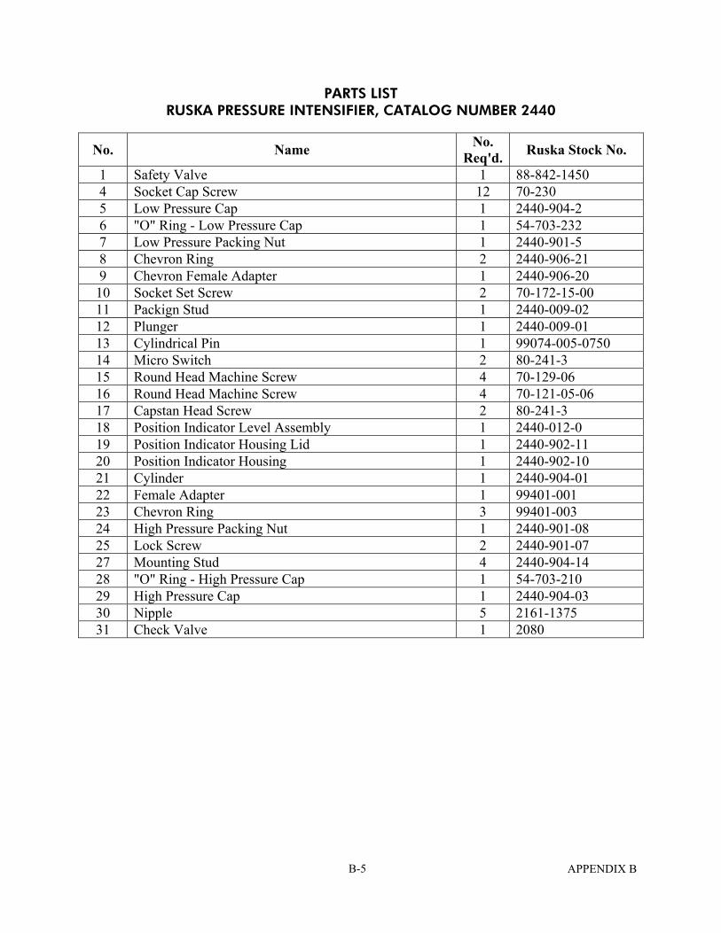
PARTS LIST RUSKA PRESSURE INTENSIFIER, CATALOG NUMBER 2440
No. Name No. Req'd. Ruska Stock No.
1 Safety Valve 1 88-842-1450 4 Socket Cap Screw 12 70-230 5 Low Pressure Cap 1 2440-904-2 6 "O" Ring - Low Pressure Cap 1 54-703-232 7 Low Pressure Packing Nut 1 2440-901-5 8 Chevron Ring 2 2440-906-21 9 Chevron Female Adapter 1 2440-906-20 10 Socket Set Screw 2 70-172-15-00 11 Packign Stud 1 2440-009-02 12 Plunger 1 2440-009-01 13 Cylindrical Pin 1 99074-005-0750 14 Micro Switch 2 80-241-3 15 Round Head Machine Screw 4 70-129-06 16 Round Head Machine Screw 4 70-121-05-06 17 Capstan Head Screw 2 80-241-3 18 Position Indicator Level Assembly 1 2440-012-0 19 Position Indicator Housing Lid 1 2440-902-11 20 Position Indicator Housing 1 2440-902-10 21 Cylinder 1 2440-904-01 22 Female Adapter 1 99401-001 23 Chevron Ring 3 99401-003 24 High Pressure Packing Nut 1 2440-901-08 25 Lock Screw 2 2440-901-07 27 Mounting Stud 4 2440-904-14 28 "O" Ring - High Pressure Cap 1 54-703-210 29 High Pressure Cap 1 2440-904-03 30 Nipple 5 2161-1375 31 Check Valve 1 2080
APPENDIX B B-5
For the type maintenance proceed as follows (all numbers refer to item sequence numbers in Figure B-2):
1. Disconnect the electrical input from the mains. 2. Close the bottle valves and vent the entire system to atmosphere. 3. Disconnect all pressure lines attached to the intensifier body, No. 0011. 4. With appropriate temporary support from beneath the table, remove the four 3/8"
mounting bolts and allow the intensifier body with its hanger straps to rest on the support.
5. Place the unit on a bench where the electrical signal box (No. 0010) and the relief valve (No. 0018/0019) may be removed. These items are not a part of the clean system and need not be re-cleaned. Do not damage the tamper-proof seal and wire on the relief valve.
6. Transfer the unit to a cleaning station where the operations can be conducted in the appropriate environment.
7. Remove the two end caps from the intensifier body; the end cap seals are standard piston O-rings placed in their respective grooves. When removing these O-rings, a hard metal tool must NOT be used because of the danger of scratching the root surface of the groove; a soft aluminum rod sharpened on one end may be used. Inspect the O.D. of these O-rings for assessment of damage, if any, from use. Observe especially if the smaller of the two (from high-pressure end) shows signs of extrusions on the O.D.
8. Remove the piston assembly by forcing it out through the low-pressure end of the body. The piston may be forced out of the body by a plastic or aluminum rod end which is wrapped with lint-free paper. The piston may then be disassembled by the removal of seal-retaining caps and seals.
9. Replacement of the checkvalve poppet O-rings, Ruska P/N 54-903-2, (2) may be completed by breaking the threaded (right-hand) joint between the 1-3/16 inch hexagon body and the 13/16 inch hex fitting retainer. See Figure B-3. The poppet will then be exposed. By leaving the body of the input valve attached to the high-pressure cap, there will be little confusion on reassembly.
FIGURE B-3 CHECK VALVE
APPENDIX B B-6
10. Clean the parts by whatever procedures for this class of equipment are specified.
11. Upon reassembly, the sealing surfaces and seals should be coated with a light film of Krytox 240AA (Ruska #45-339) grease. The parts are reassembled then in reverse order. The low-pressure cap screws are torqued to 20-25 foot-pounds and those of the high-pressure cap, also, to 20-25 ft-lbs.
Replace the stroke-limit switch box and the check valve. Orient the valve with the exhaust port directed toward the table top to deflect the gas from an operator or observer.
12. Reassemble the intensifier to the table and connect the pressure lines. Test the unit for assurance that the maintenance ha been successful.
APPENDIX B B-7

THIS PAGE INTENTIONALLY LEFT BLANK
APPENDIX B B-8
APPENDIX C RUSKA HAND PUMP
15,000 PSI WORKING PRESSURE CATALOG NUMBER 2426-825
The RUSKA Model 2426-825 hand pump was prepared for adjustment of pure helium at pressures up to 15,000 psi. It is used for adjusting the pressure within a gas-operated system in which the medium may come in contact with components that are intended for subsequent exposure to pure oxygen. This type of service requires exclusion of hydrocarbon lubricants and elastomer seals. The plunger seal is of material that satisfies this requirement and is of self-energizing design that needs no adjustment. Lubrication of the seal is obtained from a light film of oxygen-compatible grease that is applied to the plunger occasionally. Lubrication of the spindle threads and of the turnstile thrust bearings is achieved by the use of oil having comparable properties of the grease. These lubricants are present on surfaces that likely may be touched by the operator.
When it becomes necessary to renew the packing, observe the following procedures. 1. Remove all pressure from the pump by venting the entire system to the
atmosphere. 2. Wrap a single sheet of lint-free paper around the outward half of the exposed
plunger and secure it with tape. 3. Remove the Packing Retainer Nut (6) and Follow Ring (7) from the cylinder. Move
them outward to the stop collar (4). Handle them carefully to avoid the possibility of damaging the plunger surface/ the surface is critical.
4. Withdraw the Follow Ring (7) from the cylinder. 5. Remove the four mounting bolts that secure the pump base to the table. The
pump base may then be withdrawn from the cylinder without disconnecting the gags fittings.
6. Remove the seal; it is likely to have remained in the cylinder. Do not use a hard tool that may scratch the bore.
7. Apply a thin film of Krytox 240AA (Ruska #45-339) grease to the exposed surface of the plunger and to the bore of the cylinder.
8. Place the seal on the plunger with the open side (containing the O-ring) facing the cylinder. Replace the pump base assembly while working the seal into the cylinder bore. The lading edge of the seal is fragile and may be damaged if handled carelessly.
9. Secure the base to the table and restore the remaining parts to their respective places. Lock the cylinder retaining nut with the No. 456 spanner wrench.
10. Remove the paper from the plunger and apply a light coat of lubricant grease. Oil the spindle threads and thrust bearings (oil cup) with Krytox 143AZ (Ruska #45-338) oil.
11. Test the hand pump for leaks as described in the procedures for making system leak tests.
APPENDIX C C-1

THIS PAGE INTENTIONALLY LEFT BLANK
APPENDIX C C-2

APPENDIX D CATALOG INFORMATION
APPENDIX D D-1

THIS PAGE INTENTIONALLY LEFT BLANK
APPENDIX D D-2

APPENDIX E DRAWINGS AND BILLS-OF-MATERIALS
APPENDIX E E-1

THIS PAGE INTENTIONALLY LEFT BLANK
APPENDIX E E-2

APPENDIX F TEST AND CALIBRATION REPORTS
APPENDIX F F-1

THIS PAGE INTENTIONALLY LEFT BLANK
APPENDIX F F-2