rv05, rv08 and rv12 480vac models installation & operation ... · power factor >0.92 breaker...
TRANSCRIPT
MAN-000036-00 REV B
RV05, RV08 and RV12 480VAC Models Installation & Operation Manual
MAN-000036-00 REV B
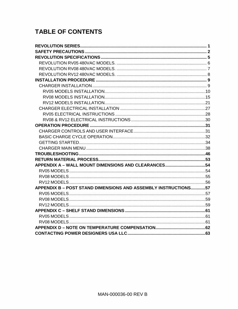
TABLE OF CONTENTS REVOLUTION SERIES ........................................................................................................ 1 SAFETY PRECAUTIONS .................................................................................................... 2 REVOLUTION SPECIFICATIONS ....................................................................................... 5
REVOLUTION RV05 480VAC MODELS. .......................................................................... 6 REVOLUTION RV08 480VAC MODELS. .......................................................................... 7 REVOLUTION RV12 480VAC MODELS. .......................................................................... 8
INSTALLATION PROCEDURE ........................................................................................... 9 CHARGER INSTALLATION .............................................................................................. 9
RV05 MODELS INSTALLATION...................................................................................10 RV08 MODELS INSTALLATION...................................................................................15 RV12 MODELS INSTALLATION...................................................................................21
CHARGER ELECTRICAL INSTALLATION ......................................................................27 RV05 ELECTRICAL INSTRUCTIONS ..........................................................................28 RV08 & RV12 ELECTRICAL INSTRUCTIONS .............................................................30
OPERATION PROCEDURE ...............................................................................................31 CHARGER CONTROLS AND USER INTERFACE ...........................................................31 BASIC CHARGE CYCLE OPERATION ............................................................................32 GETTING STARTED ........................................................................................................34 CHARGER MAIN MENU ..................................................................................................38
TROUBLESHOOTING ........................................................................................................46 RETURN MATERIAL PROCESS ........................................................................................53 APPENDIX A – WALL MOUNT DIMENSIONS AND CLEARANCES .................................54
RV05 MODELS ................................................................................................................54 RV08 MODELS ................................................................................................................55 RV12 MODELS ................................................................................................................56
APPENDIX B – POST STAND DIMENSIONS AND ASSEMBLY INSTRUCTIONS ............57 RV05 MODELS ................................................................................................................57 RV08 MODELS ................................................................................................................59 RV12 MODELS ................................................................................................................59
APPENDIX C – SHELF STAND DIMENSIONS ..................................................................61 RV05 MODELS ................................................................................................................61 RV08 MODELS ................................................................................................................61
APPENDIX D – NOTE ON TEMPERATURE COMPENSATION .........................................62 CONTACTING POWER DESIGNERS USA LLC ................................................................63

MAN-000036-00 REV B 1
REVOLUTION SERIES
The REVOLUTION Series features very high charge cycle efficiencies and state-of-the-art MOSFET soft-switching technology resulting in lower energy costs, smaller sizes, and lighter weight units. The REVOLUTION chargers maintain the charging efficiency greater than 90% over the entire charge cycle. This results in true energy savings of 6% or greater as compared to leading HF chargers. For a typical 36V/850Ahr battery, these savings will translate into approximately 1.5kWhr per charge cycle. In a typical application, the savings can be greater than 400kWhr per battery per year.
The REVOLUTION Series is a combination of cutting edge charging and energy management technologies, with a smaller footprint, lower acquisition costs, easy maintenance, and flexible configurations. The REVOLUTION chargers can support conventional, opportunity, and fast charge cycles. The REVOLUTION chargers also offer programmability. All charger settings and features can be easily customized to match workloads and schedules. Finish and equalize cycles may be programmed to automatically run on certain days of the week. Additionally, the REVOLUTION chargers may be tailored to meet the needs of any battery chemistry, including flooded, gel, and Absorbed Glass Mat (AGM) lead-acid batteries.
The REVOLUTION RV05, RV08 and RV12 480VAC Battery Charger
MAN-000036-00 REV B 2
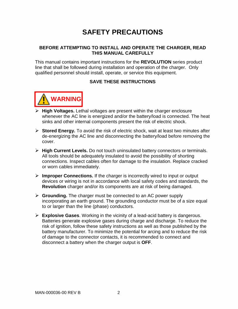
SAFETY PRECAUTIONS
BEFORE ATTEMPTING TO INSTALL AND OPERATE THE CHARGER, READ THIS MANUAL CAREFULLY
This manual contains important instructions for the REVOLUTION series product line that shall be followed during installation and operation of the charger. Only qualified personnel should install, operate, or service this equipment.
SAVE THESE INSTRUCTIONS
High Voltages. Lethal voltages are present within the charger enclosure whenever the AC line is energized and/or the battery/load is connected. The heat sinks and other internal components present the risk of electric shock.
Stored Energy. To avoid the risk of electric shock, wait at least two minutes after de-energizing the AC line and disconnecting the battery/load before removing the cover.
High Current Levels. Do not touch uninsulated battery connectors or terminals. All tools should be adequately insulated to avoid the possibility of shorting connections. Inspect cables often for damage to the insulation. Replace cracked or worn cables immediately.
Improper Connections. If the charger is incorrectly wired to input or output devices or wiring is not in accordance with local safety codes and standards, the Revolution charger and/or its components are at risk of being damaged.
Grounding. The charger must be connected to an AC power supply incorporating an earth ground. The grounding conductor must be of a size equal to or larger than the line (phase) conductors.
Explosive Gases. Working in the vicinity of a lead-acid battery is dangerous. Batteries generate explosive gases during charge and discharge. To reduce the risk of ignition, follow these safety instructions as well as those published by the battery manufacturer. To minimize the potential for arcing and to reduce the risk of damage to the connector contacts, it is recommended to connect and disconnect a battery when the charger output is OFF.
WARNING

MAN-000036-00 REV B 3
Chemical Hazard. Working with lead-acid batteries may result in exposure to highly corrosive acid. To protect eyes and skin, use the required Personal Protective Equipment (PPE) as mandated by your employer and local regulations. At a minimum, wear safety goggles and skin protection while connecting the battery charger or working in the vicinity of lead-acid batteries.
Follow the battery manufacturer's published instructions when installing, charging, and servicing batteries.
Use only with rechargeable batteries. Do not attempt to charge other battery types; doing so may cause equipment damage and result in serious personal injury.
Do not expose the charger to rain or snow. The charger is NOT designed for outdoor use.
Adequate Cooling Required. To prevent damage from overheating, proper
airflow must be ensured. Do not restrict fan inlets or exhaust outlets. Do not mount the charger in a confined space or where the exhaust air will recirculate.
No User Serviceable Parts. If service is required, contact Power Designers USA LLC or its service representative.
These instructions assume a certain level of competence by the installer and/or user. The following practices and codes contain relevant information, and should be consulted for safe installation, testing, handling, and maintenance of rechargeable lead-acid batteries. All applicable state and local codes must be followed.
• National Electrical Safety Code (NESC), ANSI/IEEE C2-2007 (or latest revision). Copies may be obtained by contacting: The Institute of Electrical and Electronics Engineers, Inc. (IEEE), Publications Office, 10662 Los Vaqueros Circle, P.O. Box 3014, Los Alamitos, CA 90720 www.ieee.org
• National Electrical Code (NEC) NFPA-70 (or latest version) available from: National Fire Protection Association, 1 Batterymarch Park, Quincy, MA 02269 www.nfpa.org
CAUTION
WARNING

MAN-000036-00 REV B 4
• Federal Codes 29CFR1926.441 Batteries and Battery Chargers 29CFR1910.305 (j) Wiring Methods, Components and Equipment for General Use OSHA Directive STD 01-08-002, including 29CFR1910.151(c) Medical Services and First Aid; 29CFR1926.50 and 29CFR1926.51, Medical Service and First Aid, and Sanitation, respectively; applicable to electric storage battery charging and maintenance areas.
• EMC Compliance This device complies with Part 15 section 103 of FCC Rules as a digital device used exclusively as a power system in public utilities or industrial plants. Operation is subject to the following two conditions:
1. This device may not cause harmful interference.
2. This device must accept any interference received, including interference that may cause undesired operation.
MAN-000036-00 REV B 5
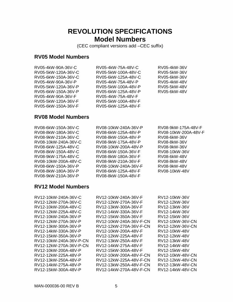
REVOLUTION SPECIFICATIONS Model Numbers
(CEC compliant versions add –CEC suffix)
RV05 Model Numbers
RV05-4kW-90A-36V-C RV05-5kW-120A-36V-C RV05-6kW-150A-36V-C RV05-4kW-90A-36V-P RV05-5kW-120A-36V-P RV05-6kW-150A-36V-P RV05-4kW-90A-36V-F RV05-5kW-120A-36V-F RV05-6kW-150A-36V-F
RV05-4kW-75A-48V-C RV05-5kW-100A-48V-C RV05-6kW-125A-48V-C RV05-4kW-75A-48V-P RV05-5kW-100A-48V-P RV05-6kW-125A-48V-P RV05-4kW-75A-48V-F RV05-5kW-100A-48V-F RV05-6kW-125A-48V-F
RV05-4kW-36V RV05-5kW-36V RV05-6kW-36V RV05-4kW-48V RV05-5kW-48V RV05-6kW-48V
RV08 Model Numbers
RV08-6kW-150A-36V-C RV08-8kW-180A-36V-C RV08-9kW-210A-36V-C RV08-10kW-240A-36V-C RV08-6kW-125A-48V-C RV08-8kW-150A-48V-C RV08-9kW-175A-48V-C RV08-10kW-200A-48V-C RV08-6kW-150A-36V-P RV08-8kW-180A-36V-P RV08-9kW-210A-36V-P
RV08-10kW-240A-36V-P RV08-6kW-125A-48V-P RV08-8kW-150A-48V-P RV08-9kW-175A-48V-P RV08-10kW-200A-48V-P RV08-6kW-150A-36V-F RV08-8kW-180A-36V-F RV08-9kW-210A-36V-F RV08-10kW-240A-36V-F RV08-6kW-125A-48V-F RV08-8kW-150A-48V-F
RV08-9kW-175A-48V-F RV08-10kW-200A-48V-F RV08-6kW-36V RV08-8kW-36V RV08-9kW-36V RV08-10kW-36V RV08-6kW-48V RV08-8kW-48V RV08-9kW-48V RV08-10kW-48V
RV12 Model Numbers
RV12-10kW-240A-36V-C RV12-12kW-270A-36V-C RV12-10kW-200A-48V-C RV12-12kW-225A-48V-C RV12-10kW-240A-36V-P RV12-12kW-270A-36V-P RV12-13kW-300A-36V-P RV12-14kW-330A-36V-P RV12-15kW-350A-36V-P RV12-10kW-240A-36V-P-CN RV12-12kW-270A-36V-P-CN RV12-10kW-200A-48V-P RV12-12kW-225A-48V-P RV12-13kW-250A-48V-P RV12-14kW-275A-48V-P RV12-15kW-300A-48V-P
RV12-10kW-240A-36V-F RV12-12kW-270A-36V-F RV12-13kW-300A-36V-F RV12-14kW-330A-36V-F RV12-15kW-350A-36V-F RV12-10kW-240A-36V-F-CN RV12-12kW-270A-36V-F-CN RV12-10kW-200A-48V-F RV12-12kW-225A-48V-F RV12-13kW-250A-48V-F RV12-14kW-275A-48V-F RV12-15kW-300A-48V-F RV12-10kW-200A-48V-F-CN RV12-12kW-225A-48V-F-CN RV12-13kW-250A-48V-F-CN RV12-14kW-270A-48V-F-CN
RV12-10kW-36V RV12-12kW-36V RV12-13kW-36V RV12-14kW-36V RV12-15kW-36V RV12-10kW-36V-CN RV12-12kW-36V-CN RV12-10kW-48V RV12-12kW-48V RV12-13kW-48V RV12-14kW-48V RV12-15kW-48V RV12-10kW-48V-CN RV12-12kW-48V-CN RV12-13kW-48V-CN RV12-14kW-48V-CN
MAN-000036-00 REV B 6
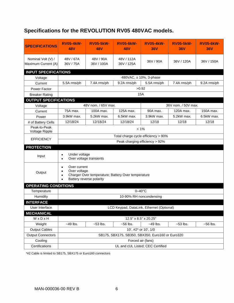
Specifications for the REVOLUTION RV05 480VAC models.
SPECIFICATIONS RV05-4kW-48V
RV05-5kW-48V
RV05-6kW-48V
RV05-4kW-36V
RV05-5kW-36V
RV05-6kW-36V
Nominal Volt (V) / Maximum Current (A)
48V / 67A 36V / 75A
48V / 90A 36V / 100A
48V / 112A 36V / 125A 36V / 90A 36V / 120A 36V / 150A
INPUT SPECIFICATIONS Voltage 480VAC, ± 10%, 3-phase Current 5.5A rms/ph 7.4A rms/ph 9.2A rms/ph 5.5A rms/ph 7.4A rms/ph 9.2A rms/ph
Power Factor >0.92 Breaker Rating 15A
OUTPUT SPECIFICATIONS Voltage 48V nom. / 65V max. 36V nom. / 50V max. Current 75A max. 100A max. 125A max. 90A max. 120A max. 150A max. Power 3.9kW max. 5.2kW max. 6.5kW max. 3.9kW max. 5.2kW max. 6.5kW max.
# of Battery Cells 12/18/24 12/18/24 12/18/24 12/18 12/18 12/18 Peak-to-Peak Voltage Ripple < 1%
EFFICIENCY Total charge cycle efficiency > 90%
Peak charging efficiency > 92% PROTECTION
Input • Under voltage • Over voltage transients
Output • Over current • Over voltage • Charger Over temperature; Battery Over temperature • Battery reverse polarity
OPERATING CONDITIONS Temperature 0–40°C
Humidity 10-90% RH noncondensing INTERFACE
User Interface LCD Keypad, DataLink, Ethernet (Optional) MECHANICAL
W x D x H 12.5” x 8.5” x 20.25” Weight ~49 lbs. ~53 lbs. ~56 lbs. ~49 lbs. ~53 lbs. ~56 lbs.
Output Cables 10’, #2* or 10’, 1/0 Output Connectors SB175, SBX175, SB350, SBX350, Euro160 or Euro320
Cooling Forced air (fans) Certifications UL and cUL Listed; CEC Certified
*#2 Cable is limited to SB175, SBX175 or Euro160 connectors

MAN-000036-00 REV B 7
Specifications for the REVOLUTION RV08 480VAC models.
SPECIFICATIONS RV08-6KW-
48V RV08-8KW-
48V RV08-9KW-
48V RV08-10KW-
48V RV08-6KW-
36V RV08-8KW-
36V RV08-9KW-
36V RV08-10KW-
36V
Nominal Volt (V) / Maximum Current (A)
48V / 112A 36V / 125A
48V / 135A 36V / 150A
48V / 157A 36V / 175A
48V / 180A 36V / 200A 36V / 150A 36V / 180A 36V / 210A 36V / 240A
INPUT SPECIFICATIONS Voltage 480VAC, 3-phase±10% Current 9.2A rms/ph 11.1A rms/ph 12.9A rms/ph 14.8A rms/ph 9.2A rms/ph 11.1A rms/ph 12.9A rms/ph 14.8A rms/ph
Power Factor >0.92 Breaker Rating 20A
OUTPUT SPECIFICATIONS Voltage 48V nom. / 65V max. 36V nom. / 50V max. Current 125A max. 150A max. 175A max. 200A max. 150A max. 180A max. 210A max. 240A max. Power 6.5kW max. 7.8kW max. 9.1kW max. 10.4kW max. 6.5kW max. 7.8kW max. 9.1kW max. 10.4kW max.
# of Battery Cells 12/18/24 12/18/24 12/18/24 12/18/24 12/18 12/18 12/18 12/18 Peak-to-Peak Voltage Ripple < 1%
EFFICIENCY Total charge cycle efficiency > 90%
Peak charging efficiency > 92% PROTECTION
Input • Under voltage • Over voltage transients
Output • Over current • Over voltage • Charger Over temperature; Battery Over temperature • Battery reverse polarity
OPERATING CONDITIONS Temperature 0–40°C
Humidity 10-90% RH noncondensing INTERFACE
User Interface LCD Keypad, DataLink, Ethernet (Optional) MECHANICAL
W x D x H 18.5” x 9.5” x 21” Weight ~73 lbs. ~77 lbs. ~81 lbs. ~85 lbs. ~73 lbs. ~77 lbs. ~81 lbs. ~85 lbs.
Output Cables 10’, 2/0 Output Connectors SB350, SBX350 or Euro320
Cooling Forced air (fans) Certifications UL and cUL Listed; CEC Certified
MAN-000036-00 REV B 8
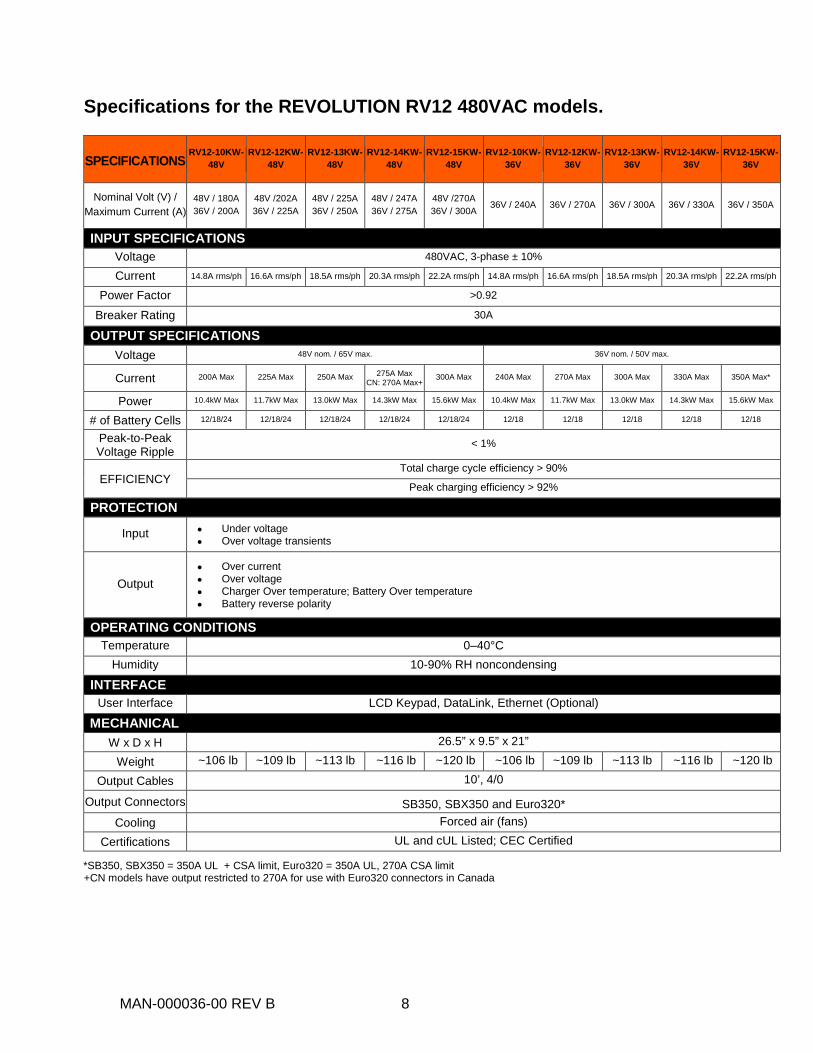
Specifications for the REVOLUTION RV12 480VAC models.
SPECIFICATIONS RV12-10KW-
48V RV12-12KW-
48V RV12-13KW-
48V RV12-14KW-
48V RV12-15KW-
48V RV12-10KW-
36V RV12-12KW-
36V RV12-13KW-
36V RV12-14KW-
36V RV12-15KW-
36V
Nominal Volt (V) / Maximum Current (A)
48V / 180A 36V / 200A
48V /202A 36V / 225A
48V / 225A 36V / 250A
48V / 247A 36V / 275A
48V /270A 36V / 300A 36V / 240A 36V / 270A 36V / 300A 36V / 330A 36V / 350A
INPUT SPECIFICATIONS Voltage 480VAC, 3-phase ± 10% Current 14.8A rms/ph 16.6A rms/ph 18.5A rms/ph 20.3A rms/ph 22.2A rms/ph 14.8A rms/ph 16.6A rms/ph 18.5A rms/ph 20.3A rms/ph 22.2A rms/ph
Power Factor >0.92 Breaker Rating 30A
OUTPUT SPECIFICATIONS Voltage 48V nom. / 65V max. 36V nom. / 50V max.
Current 200A Max 225A Max 250A Max 275A Max CN: 270A Max+
300A Max 240A Max 270A Max 300A Max 330A Max 350A Max*
Power 10.4kW Max 11.7kW Max 13.0kW Max 14.3kW Max 15.6kW Max 10.4kW Max 11.7kW Max 13.0kW Max 14.3kW Max 15.6kW Max
# of Battery Cells 12/18/24 12/18/24 12/18/24 12/18/24 12/18/24 12/18 12/18 12/18 12/18 12/18
Peak-to-Peak Voltage Ripple < 1%
EFFICIENCY Total charge cycle efficiency > 90%
Peak charging efficiency > 92% PROTECTION
Input • Under voltage • Over voltage transients
Output • Over current • Over voltage • Charger Over temperature; Battery Over temperature • Battery reverse polarity
OPERATING CONDITIONS Temperature 0–40°C
Humidity 10-90% RH noncondensing INTERFACE
User Interface LCD Keypad, DataLink, Ethernet (Optional) MECHANICAL
W x D x H 26.5” x 9.5” x 21” Weight ~106 lb ~109 lb ~113 lb ~116 lb ~120 lb ~106 lb ~109 lb ~113 lb ~116 lb ~120 lb
Output Cables 10’, 4/0 Output Connectors SB350, SBX350 and Euro320*
Cooling Forced air (fans) Certifications UL and cUL Listed; CEC Certified
*SB350, SBX350 = 350A UL + CSA limit, Euro320 = 350A UL, 270A CSA limit +CN models have output restricted to 270A for use with Euro320 connectors in Canada
MAN-000036-00 REV B 9
INSTALLATION PROCEDURE
Charger Installation The following procedure describes proper installation of the REVOLUTION series of chargers.
Charger Unpacking and Inspection
Upon receipt of a REVOLUTION charger, ensure that there is no physical damage to the chassis, the Liquid Crystal Display (LCD)/keypad, or the DC cables. If any damage is apparent, contact the shipping carrier.
Do not install or operate the charger if it has any visible damage.
Failure to meet these minimum requirements may result in a voided warranty.
• Adequate Cooling Required – To prevent damage from overheating, proper
airflow must be ensured. Do not restrict fan inlets or exhaust outlets. Do not mount the charger in a confined space or where the exhaust air will recirculate.
Continue on page 10 for RV05 Installation Procedure Continue on page 15 for RV08 Installation Procedure Continue on page 21 for RV12 Installation Procedure
WARNING
MAN-000036-00 REV B 10
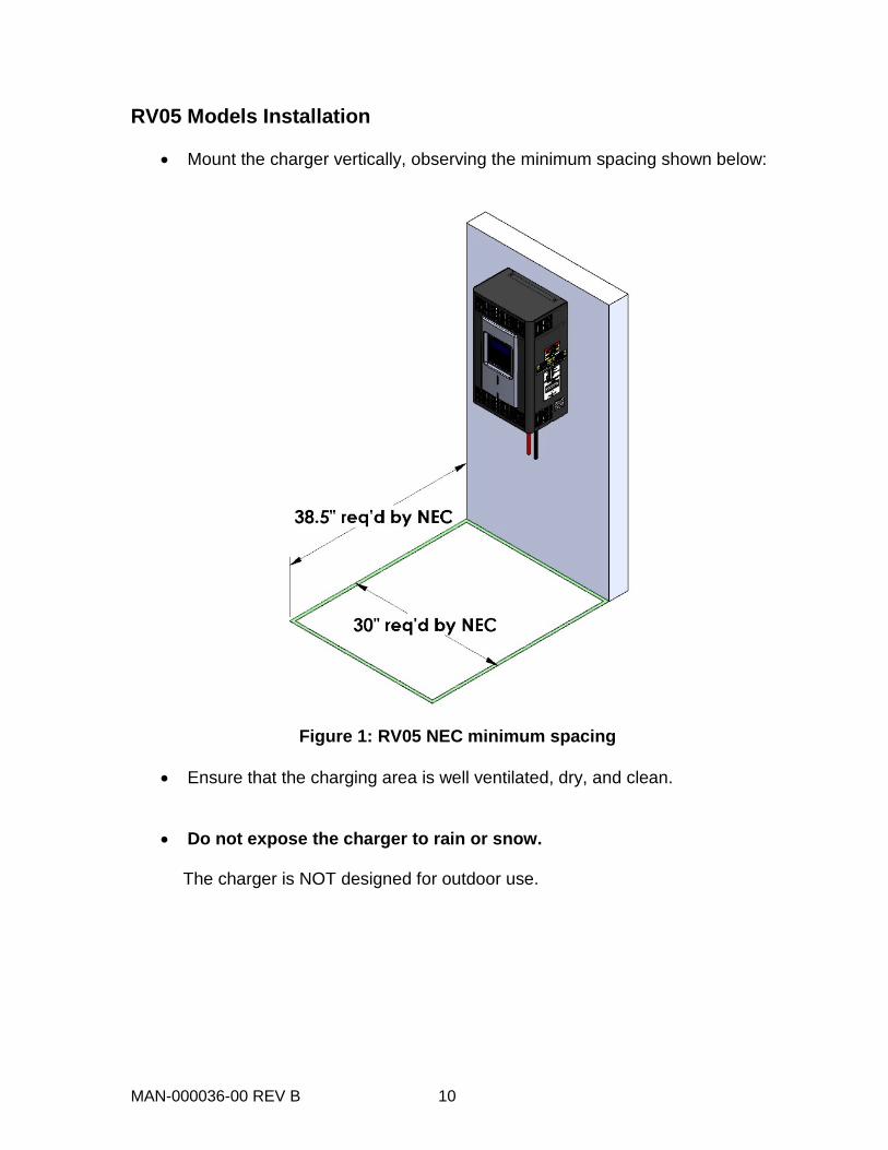
RV05 Models Installation
• Mount the charger vertically, observing the minimum spacing shown below:
Figure 1: RV05 NEC minimum spacing
• Ensure that the charging area is well ventilated, dry, and clean.
• Do not expose the charger to rain or snow.
The charger is NOT designed for outdoor use.
MAN-000036-00 REV B 11
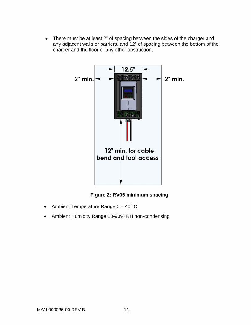
• There must be at least 2” of spacing between the sides of the charger and
any adjacent walls or barriers, and 12” of spacing between the bottom of the charger and the floor or any other obstruction.
Figure 2: RV05 minimum spacing
• Ambient Temperature Range 0 – 40° C
• Ambient Humidity Range 10-90% RH non-condensing
MAN-000036-00 REV B 12
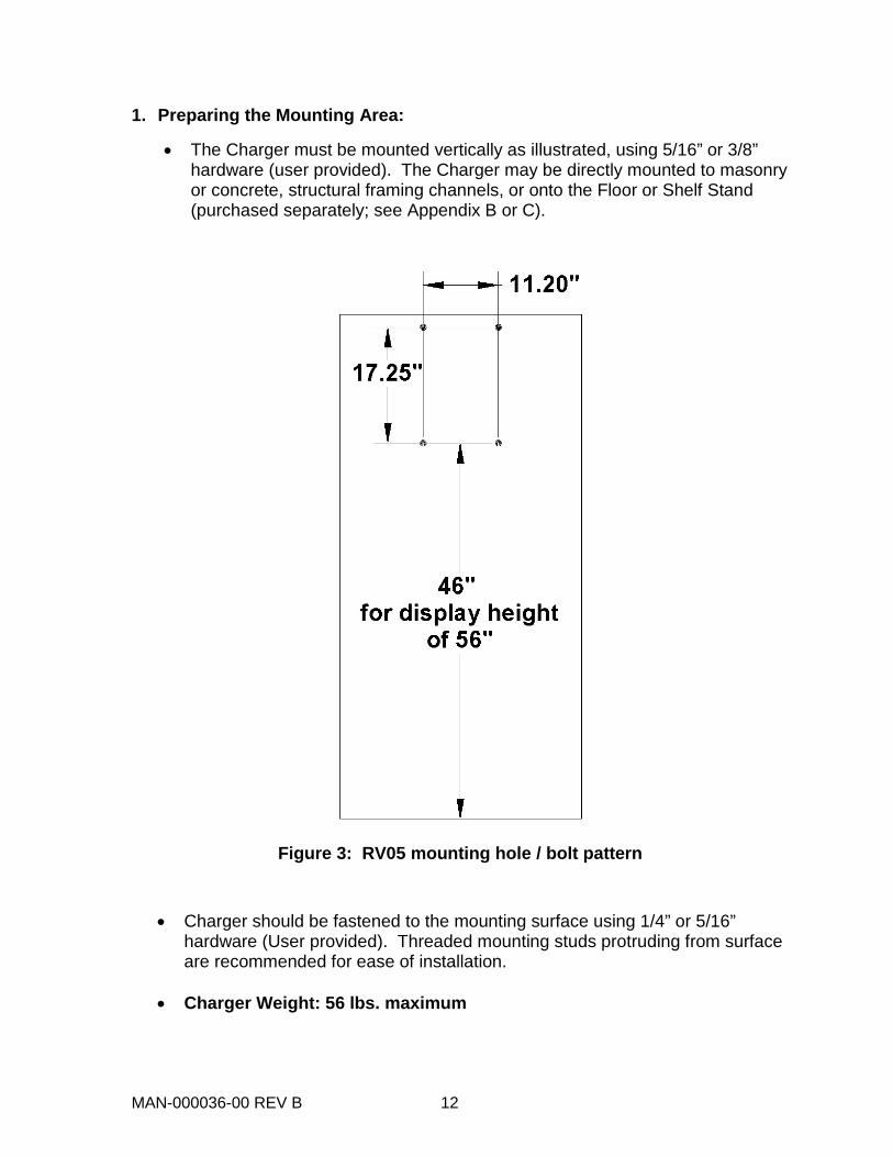
1. Preparing the Mounting Area:
• The Charger must be mounted vertically as illustrated, using 5/16” or 3/8” hardware (user provided). The Charger may be directly mounted to masonry or concrete, structural framing channels, or onto the Floor or Shelf Stand (purchased separately; see Appendix B or C).
Figure 3: RV05 mounting hole / bolt pattern
• Charger should be fastened to the mounting surface using 1/4” or 5/16” hardware (User provided). Threaded mounting studs protruding from surface are recommended for ease of installation.
• Charger Weight: 56 lbs. maximum
MAN-000036-00 REV B 13
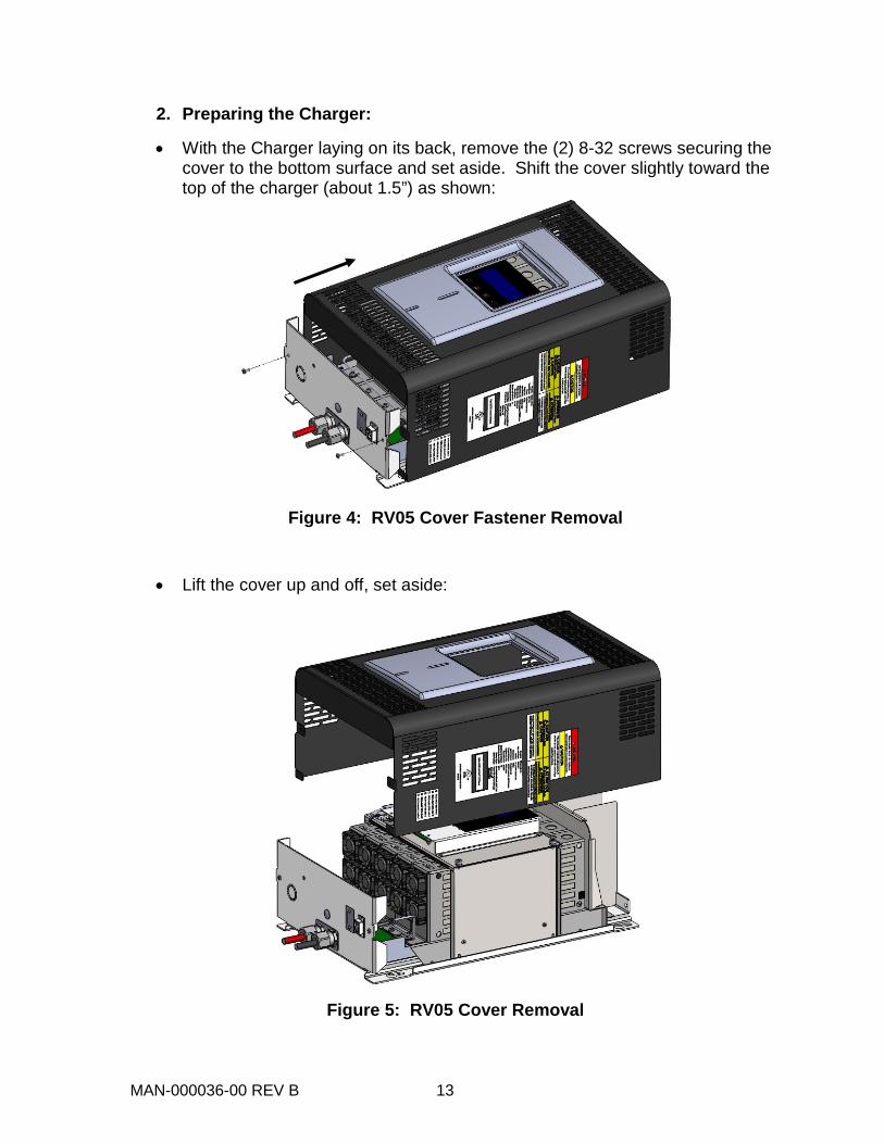
2. Preparing the Charger:
• With the Charger laying on its back, remove the (2) 8-32 screws securing the cover to the bottom surface and set aside. Shift the cover slightly toward the top of the charger (about 1.5”) as shown:
Figure 4: RV05 Cover Fastener Removal
• Lift the cover up and off, set aside:
Figure 5: RV05 Cover Removal
MAN-000036-00 REV B 14
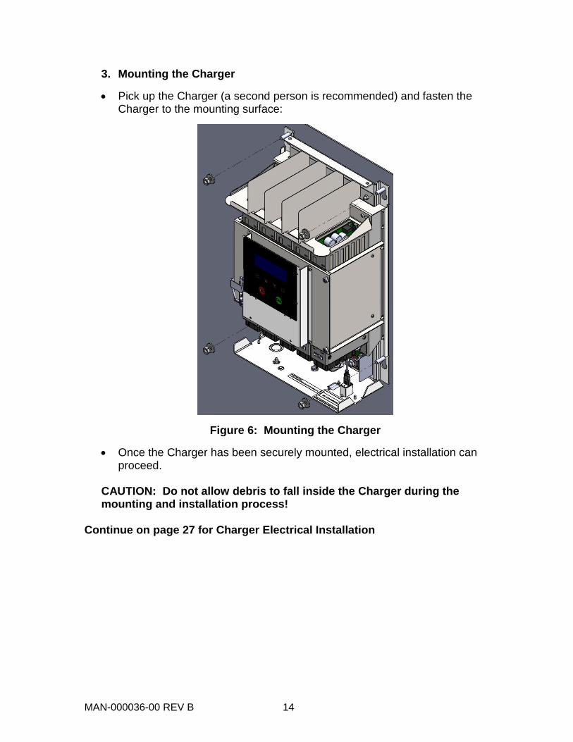
3. Mounting the Charger
• Pick up the Charger (a second person is recommended) and fasten the Charger to the mounting surface:
Figure 6: Mounting the Charger
• Once the Charger has been securely mounted, electrical installation can proceed.
CAUTION: Do not allow debris to fall inside the Charger during the mounting and installation process!
Continue on page 27 for Charger Electrical Installation
MAN-000036-00 REV B 15
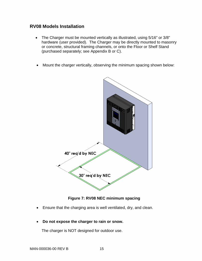
RV08 Models Installation
• The Charger must be mounted vertically as illustrated, using 5/16” or 3/8” hardware (user provided). The Charger may be directly mounted to masonry or concrete, structural framing channels, or onto the Floor or Shelf Stand (purchased separately; see Appendix B or C).
• Mount the charger vertically, observing the minimum spacing shown below:
Figure 7: RV08 NEC minimum spacing
• Ensure that the charging area is well ventilated, dry, and clean.
• Do not expose the charger to rain or snow.
The charger is NOT designed for outdoor use.

MAN-000036-00 REV B 16
• There must be at least 12” of spacing between the sides of the charger and any adjacent walls or barriers, and 12” of spacing between the bottom of the charger and the floor or any other obstruction. This is to allow for service and tool access to the Charger.
Figure 8: RV08 minimum spacing
• Ambient Temperature Range 0 – 40° C
• Ambient Humidity Range 10-90% RH non-condensing
MAN-000036-00 REV B 17
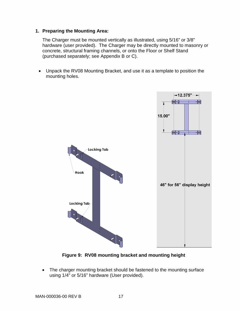
1. Preparing the Mounting Area:
The Charger must be mounted vertically as illustrated, using 5/16” or 3/8” hardware (user provided). The Charger may be directly mounted to masonry or concrete, structural framing channels, or onto the Floor or Shelf Stand (purchased separately; see Appendix B or C).
• Unpack the RV08 Mounting Bracket, and use it as a template to position the
mounting holes.
Figure 9: RV08 mounting bracket and mounting height
• The charger mounting bracket should be fastened to the mounting surface using 1/4” or 5/16” hardware (User provided).
MAN-000036-00 REV B 18
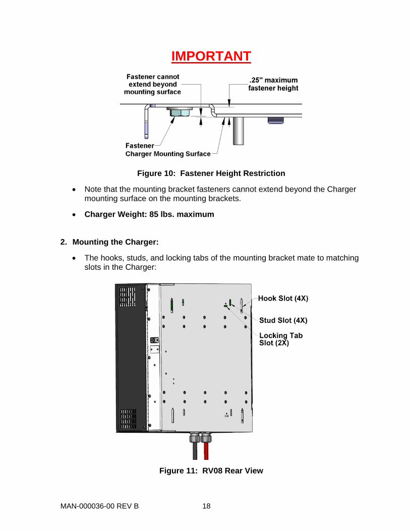
IMPORTANT
Figure 10: Fastener Height Restriction
• Note that the mounting bracket fasteners cannot extend beyond the Charger mounting surface on the mounting brackets.
• Charger Weight: 85 lbs. maximum 2. Mounting the Charger:
• The hooks, studs, and locking tabs of the mounting bracket mate to matching slots in the Charger:
Figure 11: RV08 Rear View
MAN-000036-00 REV B 19
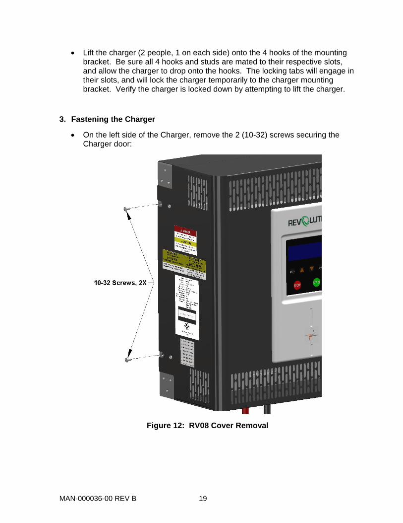
• Lift the charger (2 people, 1 on each side) onto the 4 hooks of the mounting bracket. Be sure all 4 hooks and studs are mated to their respective slots, and allow the charger to drop onto the hooks. The locking tabs will engage in their slots, and will lock the charger temporarily to the charger mounting bracket. Verify the charger is locked down by attempting to lift the charger.
3. Fastening the Charger
• On the left side of the Charger, remove the 2 (10-32) screws securing the Charger door:
Figure 12: RV08 Cover Removal

MAN-000036-00 REV B 20
• Swing the Charger open to expose the studs of the Mounting Bracket, and the plastic bag containing the mounting nuts:
Figure 13: RV08 Cover open
• Remove the nuts from the bag, and use them to secure the Charger. Tighten to 60 in-lb +/- 2 in-lb:
Figure 14: RV08 Permanent Attachment
• Once the Charger has been securely mounted, electrical installation can proceed.
CAUTION: Do not allow debris to fall inside the Charger during the mounting and installation process!
Continue on page 27 for Charger Electrical Installation
MAN-000036-00 REV B 21
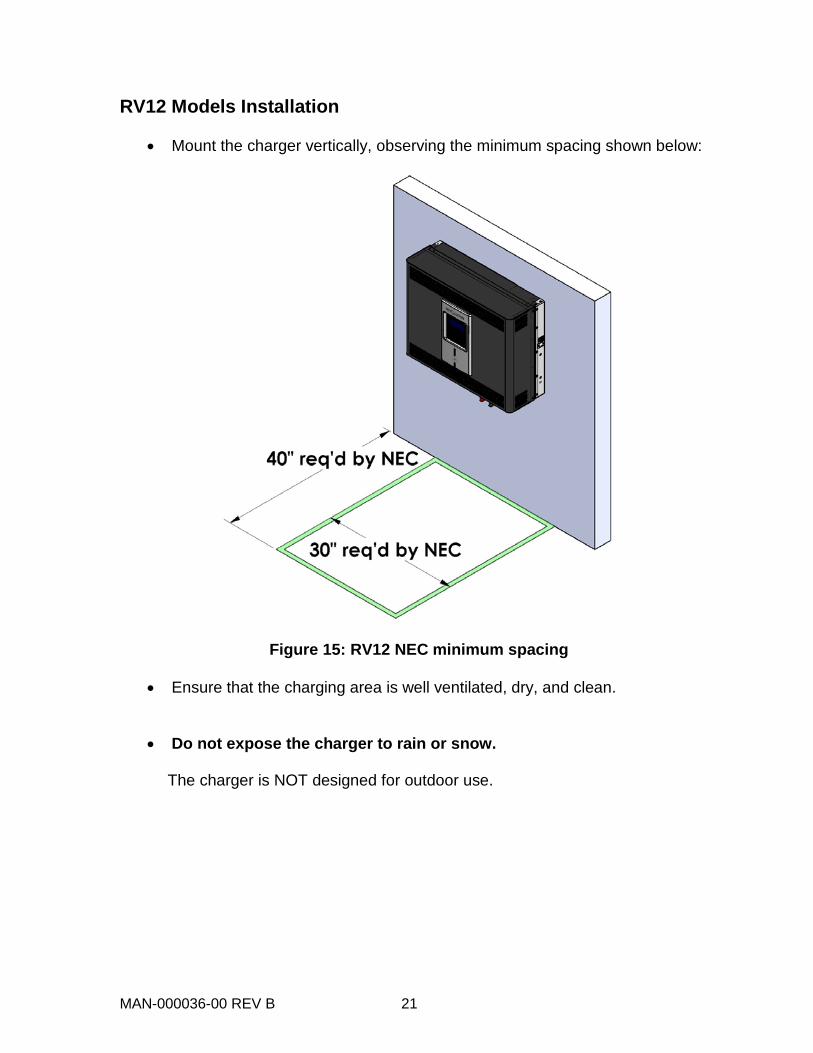
RV12 Models Installation
• Mount the charger vertically, observing the minimum spacing shown below:
Figure 15: RV12 NEC minimum spacing
• Ensure that the charging area is well ventilated, dry, and clean.
• Do not expose the charger to rain or snow.
The charger is NOT designed for outdoor use.
MAN-000036-00 REV B 22
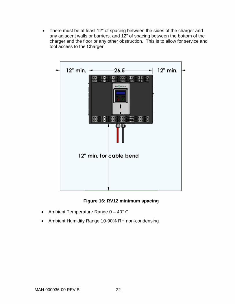
• There must be at least 12” of spacing between the sides of the charger and any adjacent walls or barriers, and 12” of spacing between the bottom of the charger and the floor or any other obstruction. This is to allow for service and tool access to the Charger.
Figure 16: RV12 minimum spacing
• Ambient Temperature Range 0 – 40° C
• Ambient Humidity Range 10-90% RH non-condensing
MAN-000036-00 REV B 23
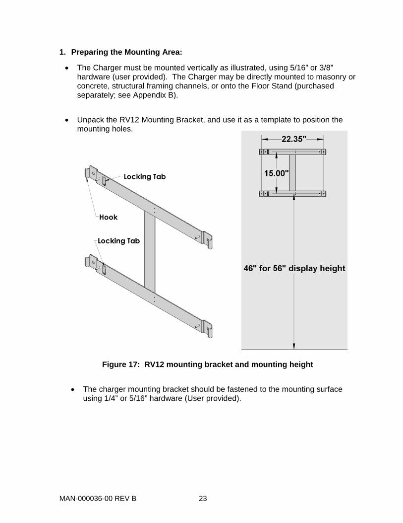
1. Preparing the Mounting Area:
• The Charger must be mounted vertically as illustrated, using 5/16” or 3/8” hardware (user provided). The Charger may be directly mounted to masonry or concrete, structural framing channels, or onto the Floor Stand (purchased separately; see Appendix B).
• Unpack the RV12 Mounting Bracket, and use it as a template to position the
mounting holes.
Figure 17: RV12 mounting bracket and mounting height
• The charger mounting bracket should be fastened to the mounting surface
using 1/4” or 5/16” hardware (User provided).

MAN-000036-00 REV B 24
IMPORTANT
Figure 18: Fastener Height Restriction
• Note that the mounting bracket fasteners cannot extend beyond the Charger mounting surface on the mounting brackets.
• Charger Weight: 120 lbs. maximum
2. Mounting the Charger:
• The hooks, studs, and locking tabs of the mounting bracket mate to matching slots in the Charger:
Figure 19: RV12 Rear View
• Lift the charger (2 people, 1 on each side) onto the 4 hooks of the mounting bracket. Be sure all 4 hooks and studs are mated to their respective slots, and allow the charger to drop onto the hooks. The locking tabs will engage in their slots, and will lock the charger temporarily to the charger mounting bracket. Verify the charger is locked down by attempting to lift the charger.
MAN-000036-00 REV B 25
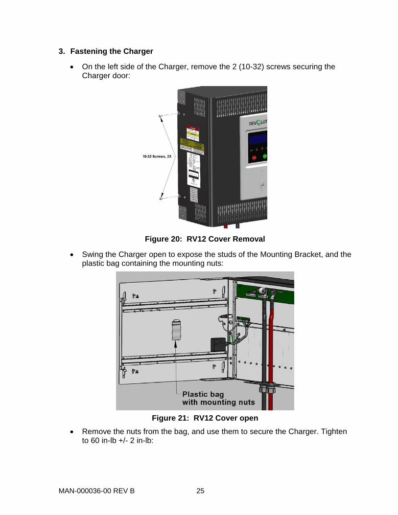
3. Fastening the Charger
• On the left side of the Charger, remove the 2 (10-32) screws securing the Charger door:
Figure 20: RV12 Cover Removal
• Swing the Charger open to expose the studs of the Mounting Bracket, and the plastic bag containing the mounting nuts:
Figure 21: RV12 Cover open • Remove the nuts from the bag, and use them to secure the Charger. Tighten
to 60 in-lb +/- 2 in-lb:
MAN-000036-00 REV B 26
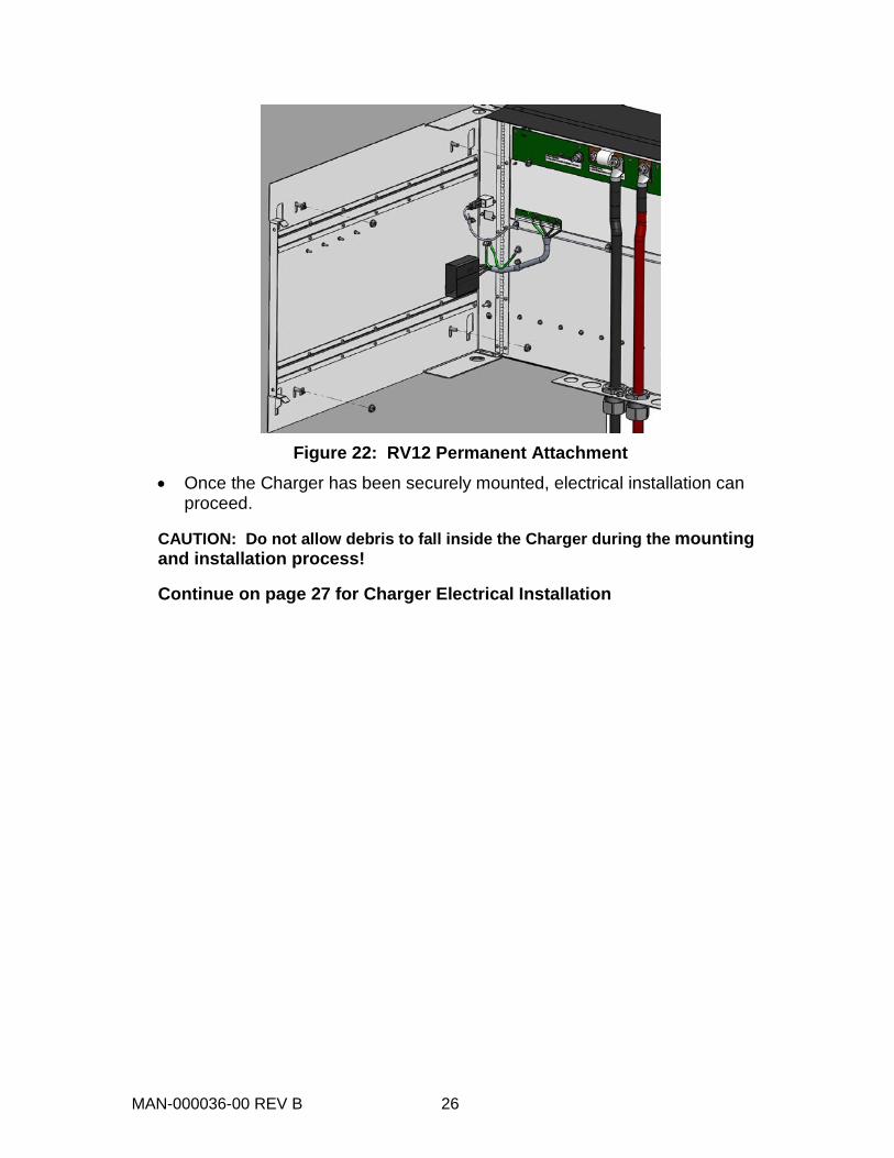
Figure 22: RV12 Permanent Attachment • Once the Charger has been securely mounted, electrical installation can
proceed. CAUTION: Do not allow debris to fall inside the Charger during the mounting and installation process! Continue on page 27 for Charger Electrical Installation
MAN-000036-00 REV B 27
Charger Electrical Installation
DANGEROUS VOLTAGES AND CURRENTS ARE PRESENT IN THE AC MAINS WHEN ENERGIZED. ONLY TRAINED PERSONNEL SHOULD PERFORM THE INSTALLATION, USING PROPER EQUIPMENT AND PROCEDURES.
VERIFY THAT INPUT AND OUTPUT WIRING ADHERES TO ALL LOCAL SAFETY CODES AND STANDARDS.
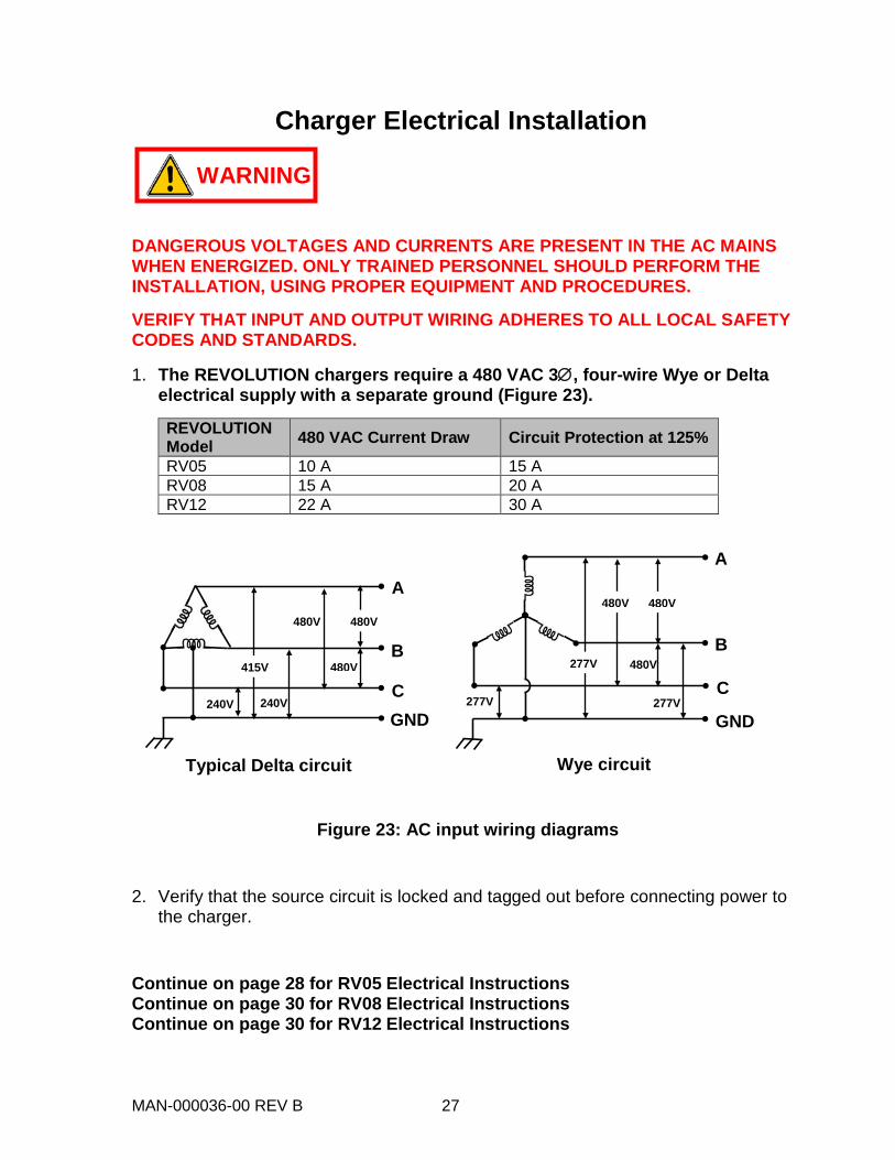
1. The REVOLUTION chargers require a 480 VAC 3∅, four-wire Wye or Delta electrical supply with a separate ground (Figure 23).
REVOLUTION Model 480 VAC Current Draw Circuit Protection at 125%
RV05 10 A 15 A RV08 15 A 20 A RV12 22 A 30 A
Figure 23: AC input wiring diagrams
2. Verify that the source circuit is locked and tagged out before connecting power to the charger.
Continue on page 28 for RV05 Electrical Instructions Continue on page 30 for RV08 Electrical Instructions Continue on page 30 for RV12 Electrical Instructions
GND
Typical Delta circuit Wye circuit
A
B
C 240V
415V
480V 480V
240V C
B
A
277V 277V
480V 277V
480V 480V
GND
480V
WARNING
MAN-000036-00 REV B 28
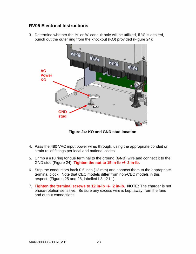
RV05 Electrical Instructions 3. Determine whether the ½” or ¾” conduit hole will be utilized, if ¾” is desired,
punch out the outer ring from the knockout (KO) provided (Figure 24):
Figure 24: KO and GND stud location
4. Pass the 480 VAC input power wires through, using the appropriate conduit or strain relief fittings per local and national codes.
5. Crimp a #10 ring tongue terminal to the ground (GND) wire and connect it to the GND stud (Figure 24). Tighten the nut to 15 in-lb +/- 2 in-lb.
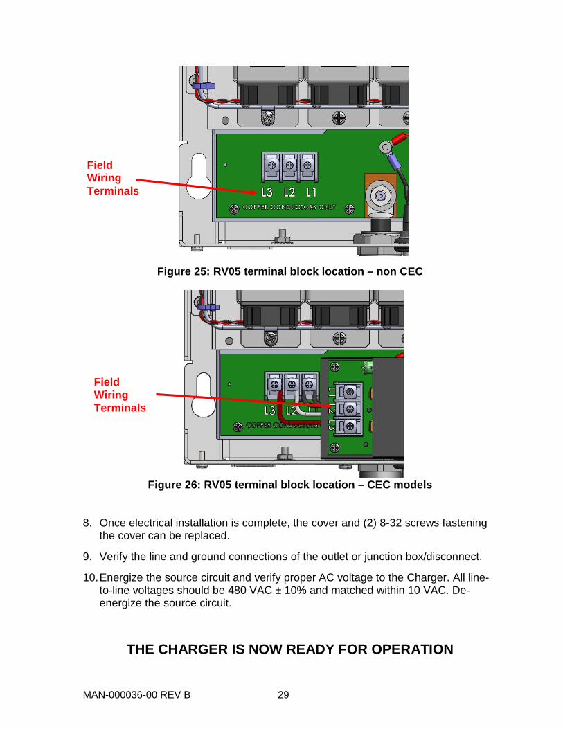
6. Strip the conductors back 0.5 inch (12 mm) and connect them to the appropriate terminal block. Note that CEC models differ from non-CEC models in this respect. (Figures 25 and 26, labelled L3 L2 L1).
7. Tighten the terminal screws to 12 in-lb +/- 2 in-lb. NOTE: The charger is not phase-rotation sensitive. Be sure any excess wire is kept away from the fans and output connections.
GND stud
AC Power KO
MAN-000036-00 REV B 29
Figure 25: RV05 terminal block location – non CEC
Figure 26: RV05 terminal block location – CEC models
8. Once electrical installation is complete, the cover and (2) 8-32 screws fastening
the cover can be replaced.
9. Verify the line and ground connections of the outlet or junction box/disconnect.
10. Energize the source circuit and verify proper AC voltage to the Charger. All line-to-line voltages should be 480 VAC ± 10% and matched within 10 VAC. De-energize the source circuit.
THE CHARGER IS NOW READY FOR OPERATION
Field Wiring Terminals
Field Wiring Terminals

MAN-000036-00 REV B 30
RV08 & RV12 Electrical Instructions 3. Determine whether the ½” or ¾” conduit hole will be utilized, if ¾” is desired,
punch out the outer ring from the knockout (KO) provided (Figure 26):
Figure 27: RV08 KO location
4. Pass the 480 VAC input power wires through, using the appropriate conduit or strain relief fittings per local and national codes.
5. Crimp a #10 ring tongue terminal to the ground (GND) wire and connect it to the GND stud (Figure 27). Tighten the nut to 15 in-lb +/- 2 in-lb.
6. Strip the conductors back 0.5 inch (12 mm) and connect them to the AC Terminal Block. Tighten the terminal screws to 12 in-lb +/- 2 in-lb. NOTE: The charger is not phase-rotation sensitive. Be sure any excess wire does not get pinched when the Charger door is closed.
7. Once the electrical connections have been made, the Charger door should be closed, and secured with the 10-32 screws previously removed. Tighten the 10-32 screws to 12 in-lb +/- 2 in-lb.
8. Verify the line and ground connections of the outlet or junction box/disconnect.
9. Energize the source circuit and verify proper AC voltage to the Charger. All line-to-line voltages should be 480 VAC ± 10% and matched within 10 VAC.
THE CHARGER IS NOW READY FOR OPERATION
MAN-000036-00 REV B 31
OPERATION PROCEDURE
Charger Controls and User Interface
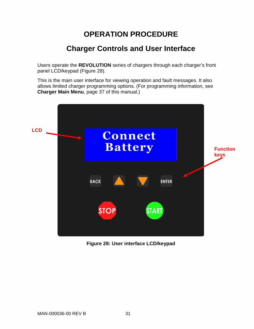
Users operate the REVOLUTION series of chargers through each charger’s front panel LCD/keypad (Figure 28).
This is the main user interface for viewing operation and fault messages. It also allows limited charger programming options. (For programming information, see Charger Main Menu, page 37 of this manual.)
Figure 28: User interface LCD/keypad
LCD
Function keys
MAN-000036-00 REV B 32
Basic Charge Cycle Operation
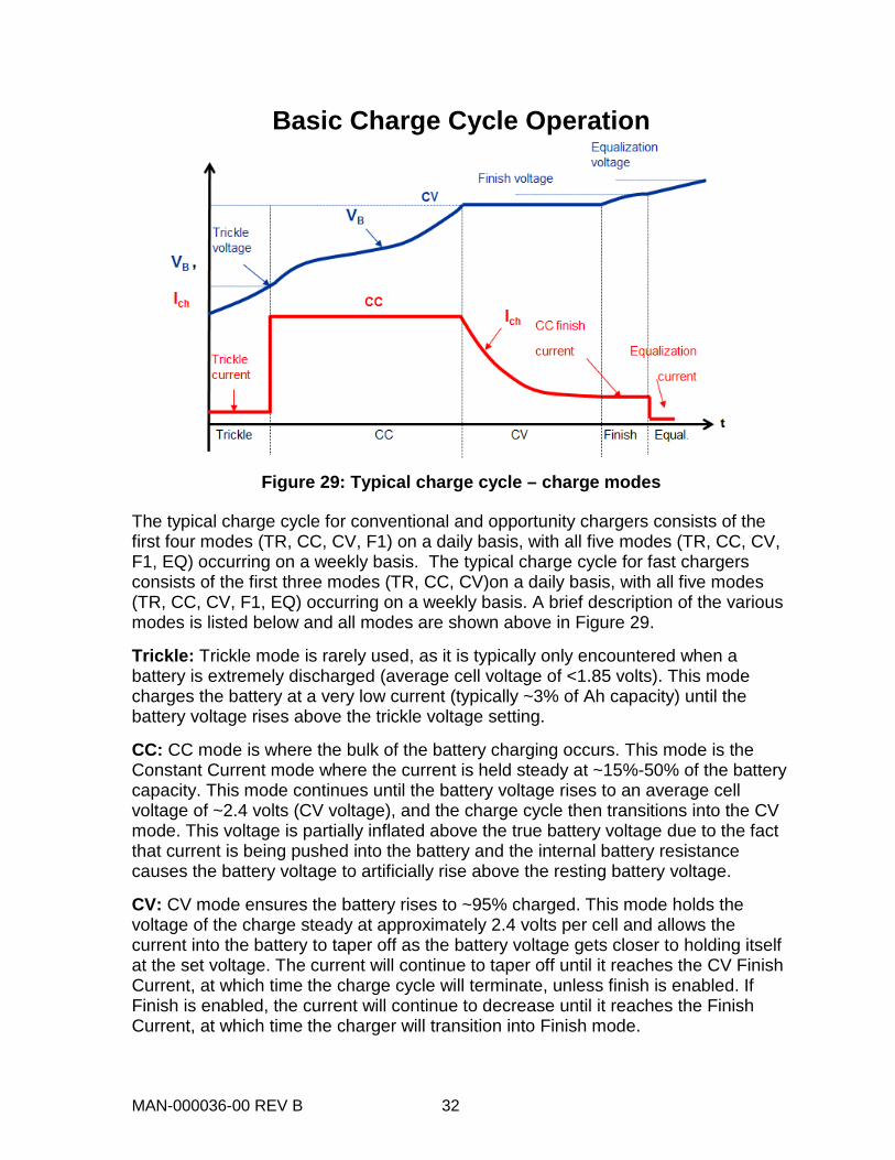
Figure 29: Typical charge cycle – charge modes
The typical charge cycle for conventional and opportunity chargers consists of the first four modes (TR, CC, CV, F1) on a daily basis, with all five modes (TR, CC, CV, F1, EQ) occurring on a weekly basis. The typical charge cycle for fast chargers consists of the first three modes (TR, CC, CV)on a daily basis, with all five modes (TR, CC, CV, F1, EQ) occurring on a weekly basis. A brief description of the various modes is listed below and all modes are shown above in Figure 29.
Trickle: Trickle mode is rarely used, as it is typically only encountered when a battery is extremely discharged (average cell voltage of <1.85 volts). This mode charges the battery at a very low current (typically ~3% of Ah capacity) until the battery voltage rises above the trickle voltage setting.
CC: CC mode is where the bulk of the battery charging occurs. This mode is the Constant Current mode where the current is held steady at ~15%-50% of the battery capacity. This mode continues until the battery voltage rises to an average cell voltage of ~2.4 volts (CV voltage), and the charge cycle then transitions into the CV mode. This voltage is partially inflated above the true battery voltage due to the fact that current is being pushed into the battery and the internal battery resistance causes the battery voltage to artificially rise above the resting battery voltage.
CV: CV mode ensures the battery rises to ~95% charged. This mode holds the voltage of the charge steady at approximately 2.4 volts per cell and allows the current into the battery to taper off as the battery voltage gets closer to holding itself at the set voltage. The current will continue to taper off until it reaches the CV Finish Current, at which time the charge cycle will terminate, unless finish is enabled. If Finish is enabled, the current will continue to decrease until it reaches the Finish Current, at which time the charger will transition into Finish mode.
MAN-000036-00 REV B 33
*48V chargers are capable of charging 24/36/48 batteries 36V chargers are capable of charging 24/36 batteries
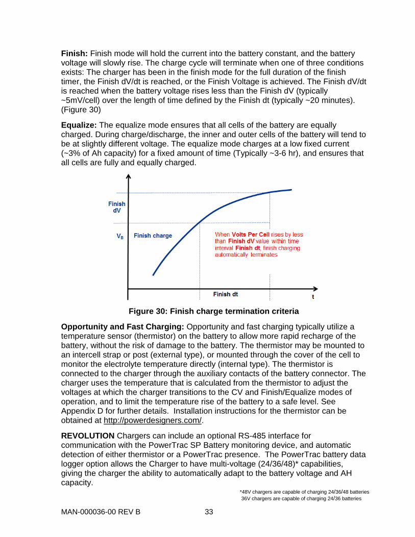
Finish: Finish mode will hold the current into the battery constant, and the battery voltage will slowly rise. The charge cycle will terminate when one of three conditions exists: The charger has been in the finish mode for the full duration of the finish timer, the Finish dV/dt is reached, or the Finish Voltage is achieved. The Finish dV/dt is reached when the battery voltage rises less than the Finish dV (typically ~5mV/cell) over the length of time defined by the Finish dt (typically ~20 minutes). (Figure 30)
Equalize: The equalize mode ensures that all cells of the battery are equally charged. During charge/discharge, the inner and outer cells of the battery will tend to be at slightly different voltage. The equalize mode charges at a low fixed current (~3% of Ah capacity) for a fixed amount of time (Typically ~3-6 hr), and ensures that all cells are fully and equally charged.
Figure 30: Finish charge termination criteria
Opportunity and Fast Charging: Opportunity and fast charging typically utilize a temperature sensor (thermistor) on the battery to allow more rapid recharge of the battery, without the risk of damage to the battery. The thermistor may be mounted to an intercell strap or post (external type), or mounted through the cover of the cell to monitor the electrolyte temperature directly (internal type). The thermistor is connected to the charger through the auxiliary contacts of the battery connector. The charger uses the temperature that is calculated from the thermistor to adjust the voltages at which the charger transitions to the CV and Finish/Equalize modes of operation, and to limit the temperature rise of the battery to a safe level. See Appendix D for further details. Installation instructions for the thermistor can be obtained at http://powerdesigners.com/.
REVOLUTION Chargers can include an optional RS-485 interface for communication with the PowerTrac SP Battery monitoring device, and automatic detection of either thermistor or a PowerTrac presence. The PowerTrac battery data logger option allows the Charger to have multi-voltage (24/36/48)* capabilities, giving the charger the ability to automatically adapt to the battery voltage and AH capacity.
MAN-000036-00 REV B 34
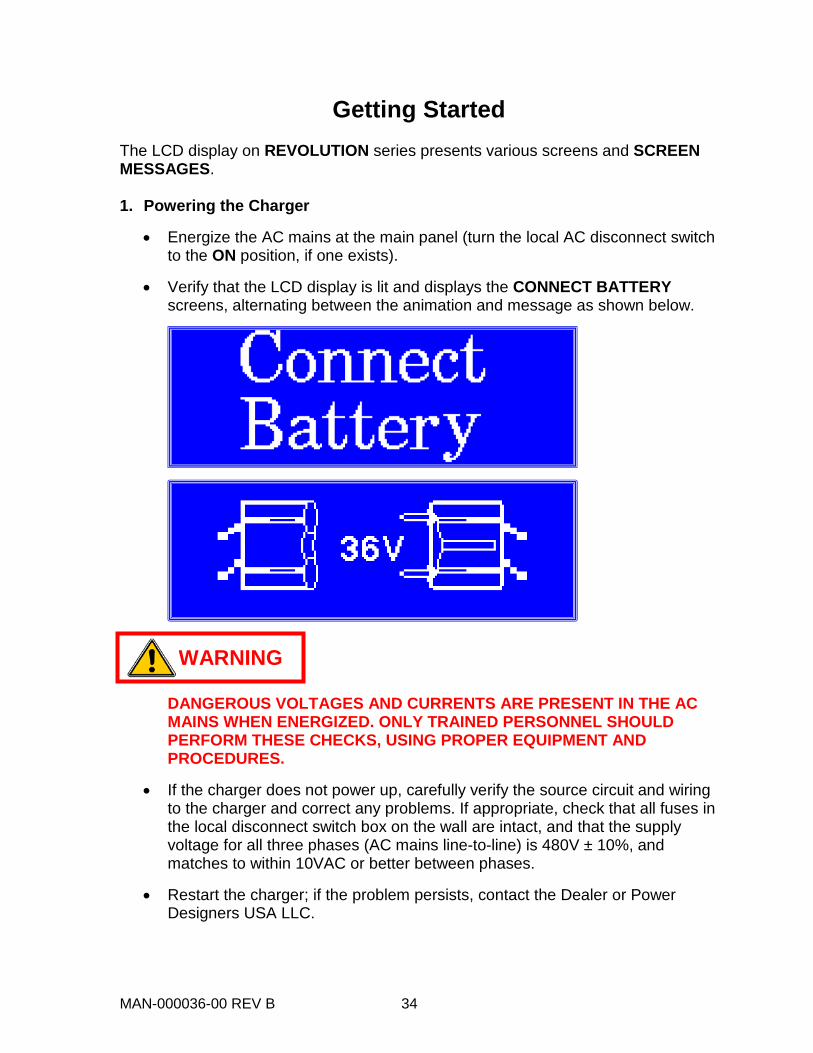
Getting Started The LCD display on REVOLUTION series presents various screens and SCREEN MESSAGES. 1. Powering the Charger
• Energize the AC mains at the main panel (turn the local AC disconnect switch to the ON position, if one exists).
• Verify that the LCD display is lit and displays the CONNECT BATTERY screens, alternating between the animation and message as shown below.
DANGEROUS VOLTAGES AND CURRENTS ARE PRESENT IN THE AC MAINS WHEN ENERGIZED. ONLY TRAINED PERSONNEL SHOULD PERFORM THESE CHECKS, USING PROPER EQUIPMENT AND PROCEDURES.
• If the charger does not power up, carefully verify the source circuit and wiring to the charger and correct any problems. If appropriate, check that all fuses in the local disconnect switch box on the wall are intact, and that the supply voltage for all three phases (AC mains line-to-line) is 480V ± 10%, and matches to within 10VAC or better between phases.
• Restart the charger; if the problem persists, contact the Dealer or Power Designers USA LLC.
WARNING
MAN-000036-00 REV B 35
2. Starting a Charge Cycle
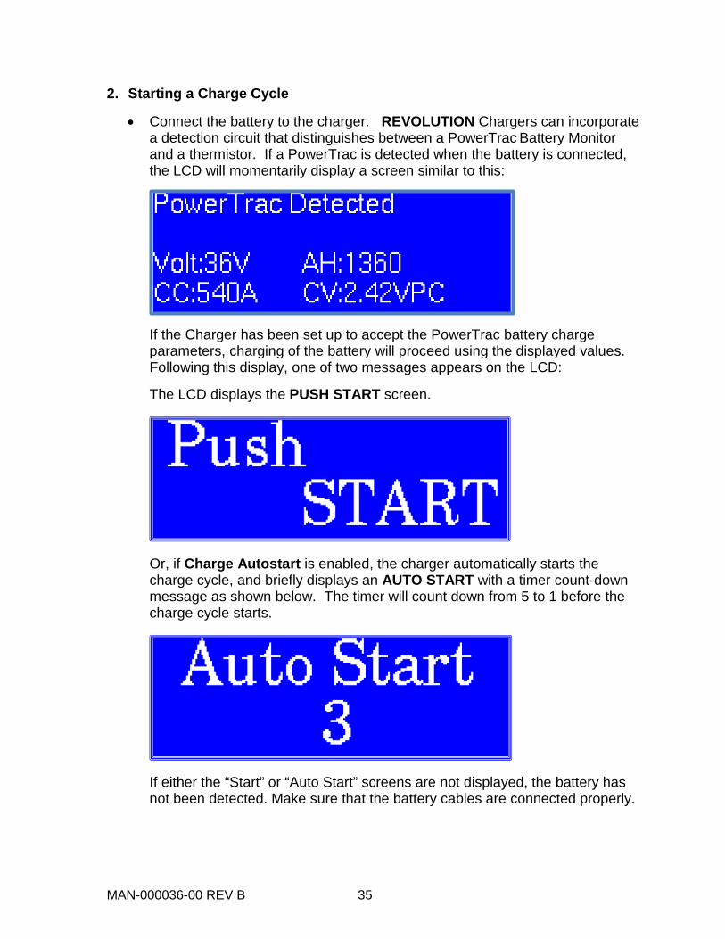
• Connect the battery to the charger. REVOLUTION Chargers can incorporate a detection circuit that distinguishes between a PowerTrac Battery Monitor and a thermistor. If a PowerTrac is detected when the battery is connected, the LCD will momentarily display a screen similar to this:
If the Charger has been set up to accept the PowerTrac battery charge parameters, charging of the battery will proceed using the displayed values. Following this display, one of two messages appears on the LCD:
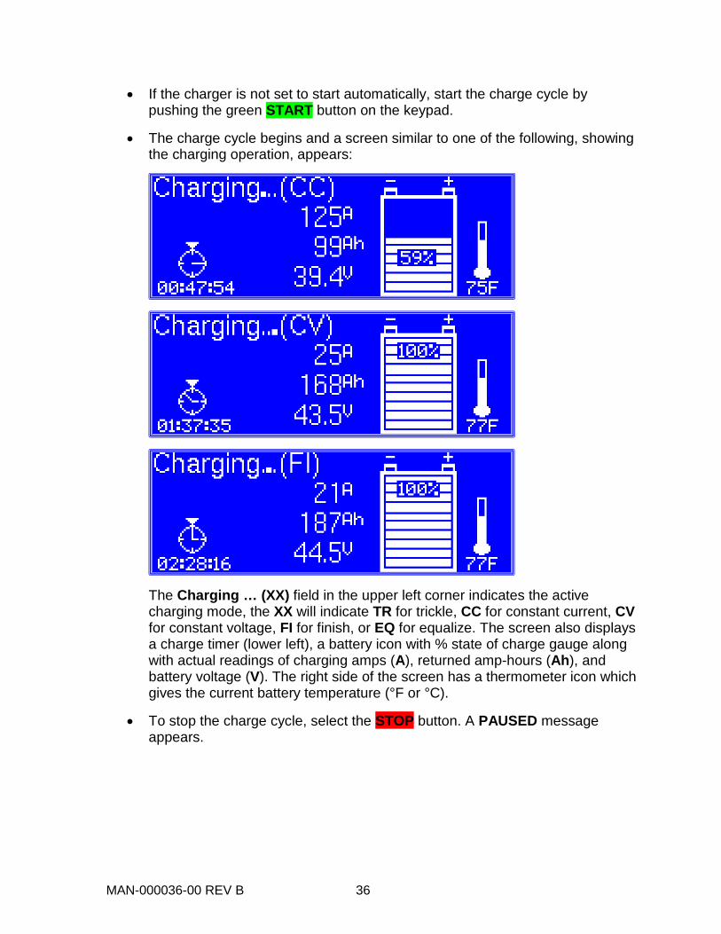
The LCD displays the PUSH START screen.
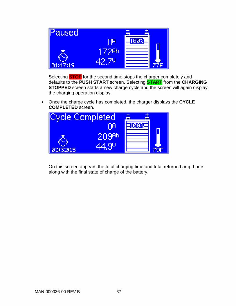
Or, if Charge Autostart is enabled, the charger automatically starts the charge cycle, and briefly displays an AUTO START with a timer count-down message as shown below. The timer will count down from 5 to 1 before the charge cycle starts.
If either the “Start” or “Auto Start” screens are not displayed, the battery has not been detected. Make sure that the battery cables are connected properly.
MAN-000036-00 REV B 36
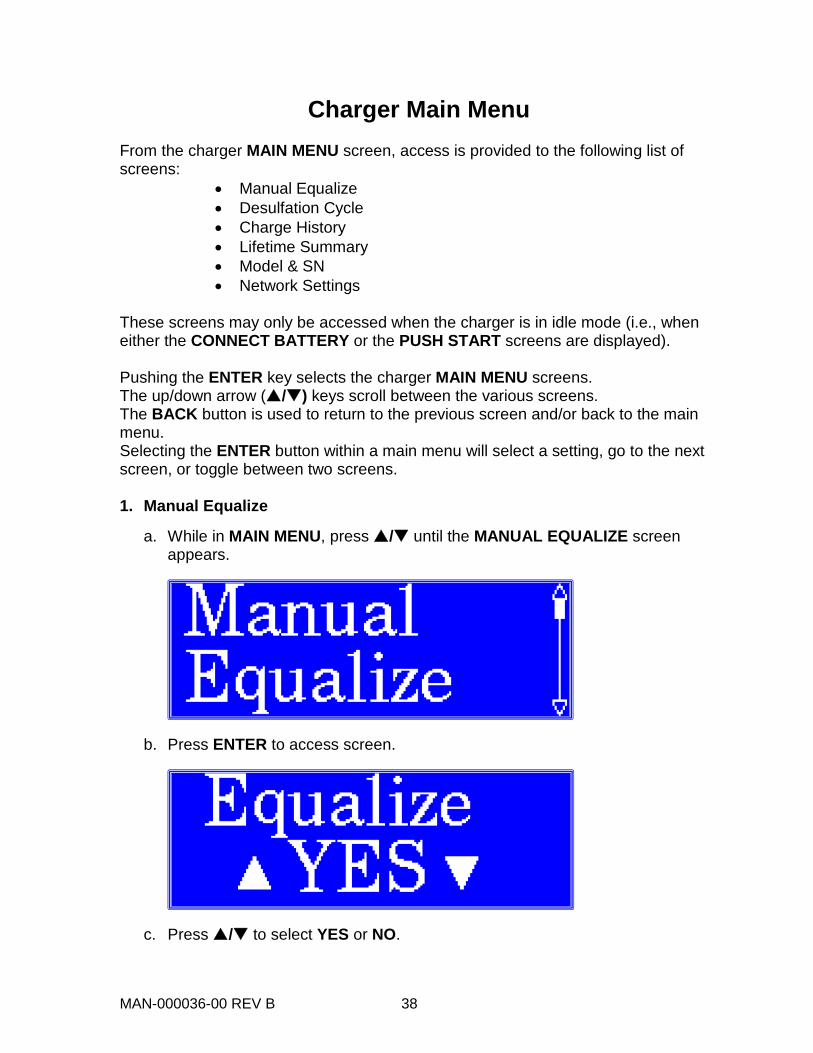
• If the charger is not set to start automatically, start the charge cycle by pushing the green START button on the keypad.
• The charge cycle begins and a screen similar to one of the following, showing the charging operation, appears:
The Charging … (XX) field in the upper left corner indicates the active charging mode, the XX will indicate TR for trickle, CC for constant current, CV for constant voltage, FI for finish, or EQ for equalize. The screen also displays a charge timer (lower left), a battery icon with % state of charge gauge along with actual readings of charging amps (A), returned amp-hours (Ah), and battery voltage (V). The right side of the screen has a thermometer icon which gives the current battery temperature (°F or °C).
• To stop the charge cycle, select the STOP button. A PAUSED message appears.
MAN-000036-00 REV B 37
Selecting STOP for the second time stops the charger completely and defaults to the PUSH START screen. Selecting START from the CHARGING STOPPED screen starts a new charge cycle and the screen will again display the charging operation display.
• Once the charge cycle has completed, the charger displays the CYCLE COMPLETED screen.
On this screen appears the total charging time and total returned amp-hours along with the final state of charge of the battery.
MAN-000036-00 REV B 38
Charger Main Menu From the charger MAIN MENU screen, access is provided to the following list of screens:
• Manual Equalize • Desulfation Cycle • Charge History • Lifetime Summary • Model & SN • Network Settings
These screens may only be accessed when the charger is in idle mode (i.e., when either the CONNECT BATTERY or the PUSH START screens are displayed). Pushing the ENTER key selects the charger MAIN MENU screens. The up/down arrow (/) keys scroll between the various screens. The BACK button is used to return to the previous screen and/or back to the main menu. Selecting the ENTER button within a main menu will select a setting, go to the next screen, or toggle between two screens. 1. Manual Equalize
a. While in MAIN MENU, press / until the MANUAL EQUALIZE screen appears.
b. Press ENTER to access screen.
c. Press / to select YES or NO.
MAN-000036-00 REV B 39
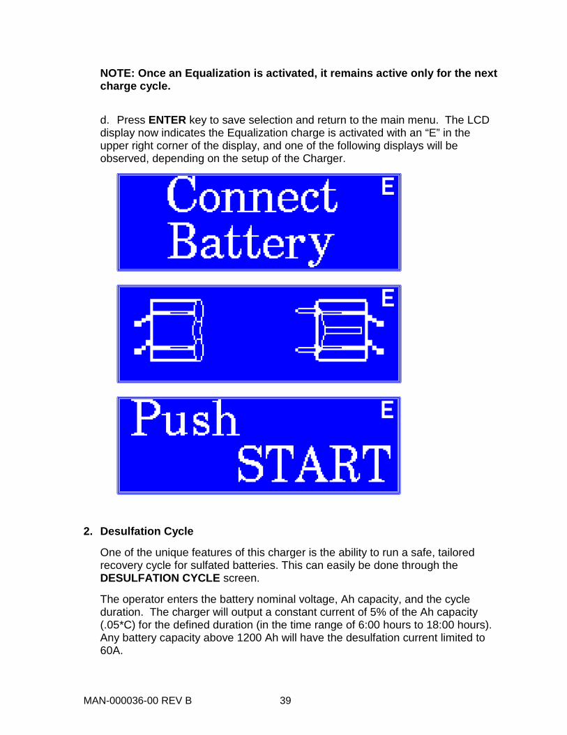
NOTE: Once an Equalization is activated, it remains active only for the next charge cycle.
d. Press ENTER key to save selection and return to the main menu. The LCD display now indicates the Equalization charge is activated with an “E” in the upper right corner of the display, and one of the following displays will be observed, depending on the setup of the Charger.
2. Desulfation Cycle
One of the unique features of this charger is the ability to run a safe, tailored recovery cycle for sulfated batteries. This can easily be done through the DESULFATION CYCLE screen.
The operator enters the battery nominal voltage, Ah capacity, and the cycle duration. The charger will output a constant current of 5% of the Ah capacity (.05*C) for the defined duration (in the time range of 6:00 hours to 18:00 hours). Any battery capacity above 1200 Ah will have the desulfation current limited to 60A.
MAN-000036-00 REV B 40
a. Connect the battery to be recovered. If the charger is set to auto-start the charge cycle, press the stop button until you are back on the “Push Start” screen.
NOTE: Do not attempt to recover a battery with a capacity of less than 250 amp-hours.
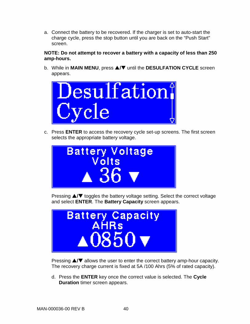
b. While in MAIN MENU, press / until the DESULFATION CYCLE screen appears.
c. Press ENTER to access the recovery cycle set-up screens. The first screen selects the appropriate battery voltage.
Pressing / toggles the battery voltage setting. Select the correct voltage and select ENTER. The Battery Capacity screen appears.
Pressing / allows the user to enter the correct battery amp-hour capacity. The recovery charge current is fixed at 5A /100 Ahrs (5% of rated capacity).
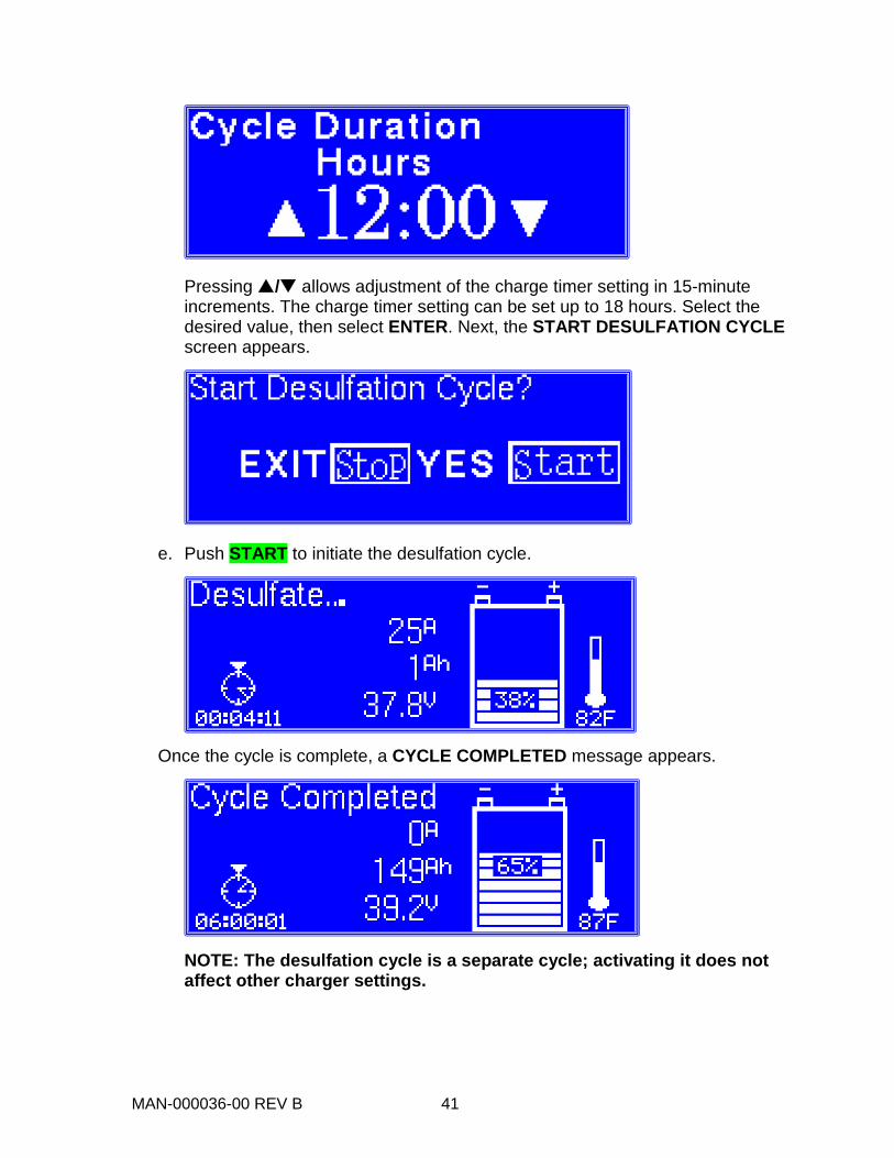
d. Press the ENTER key once the correct value is selected. The Cycle Duration timer screen appears.
MAN-000036-00 REV B 41
Pressing / allows adjustment of the charge timer setting in 15-minute increments. The charge timer setting can be set up to 18 hours. Select the desired value, then select ENTER. Next, the START DESULFATION CYCLE screen appears.
e. Push START to initiate the desulfation cycle.
Once the cycle is complete, a CYCLE COMPLETED message appears.
NOTE: The desulfation cycle is a separate cycle; activating it does not affect other charger settings.
MAN-000036-00 REV B 42
3. Charge Cycle History
a. While in MAIN MENU, press / until the CHARGE HISTORY screen appears.
Press ENTER to access the Charge History screens.
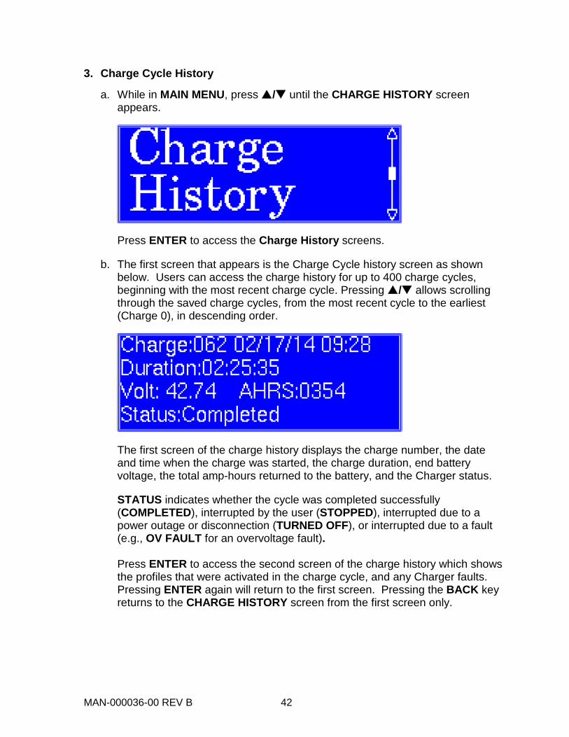
b. The first screen that appears is the Charge Cycle history screen as shown below. Users can access the charge history for up to 400 charge cycles, beginning with the most recent charge cycle. Pressing / allows scrolling through the saved charge cycles, from the most recent cycle to the earliest (Charge 0), in descending order.
The first screen of the charge history displays the charge number, the date and time when the charge was started, the charge duration, end battery voltage, the total amp-hours returned to the battery, and the Charger status.
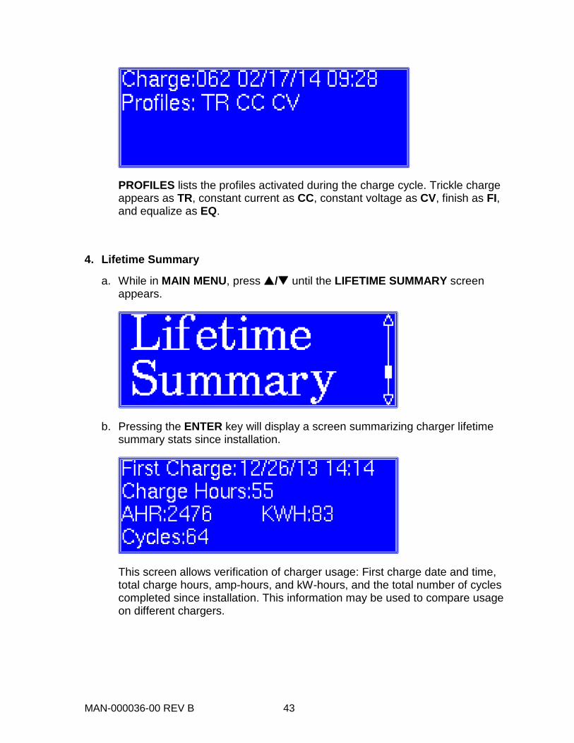
STATUS indicates whether the cycle was completed successfully (COMPLETED), interrupted by the user (STOPPED), interrupted due to a power outage or disconnection (TURNED OFF), or interrupted due to a fault (e.g., OV FAULT for an overvoltage fault). Press ENTER to access the second screen of the charge history which shows the profiles that were activated in the charge cycle, and any Charger faults. Pressing ENTER again will return to the first screen. Pressing the BACK key returns to the CHARGE HISTORY screen from the first screen only.
MAN-000036-00 REV B 43
PROFILES lists the profiles activated during the charge cycle. Trickle charge appears as TR, constant current as CC, constant voltage as CV, finish as FI, and equalize as EQ.
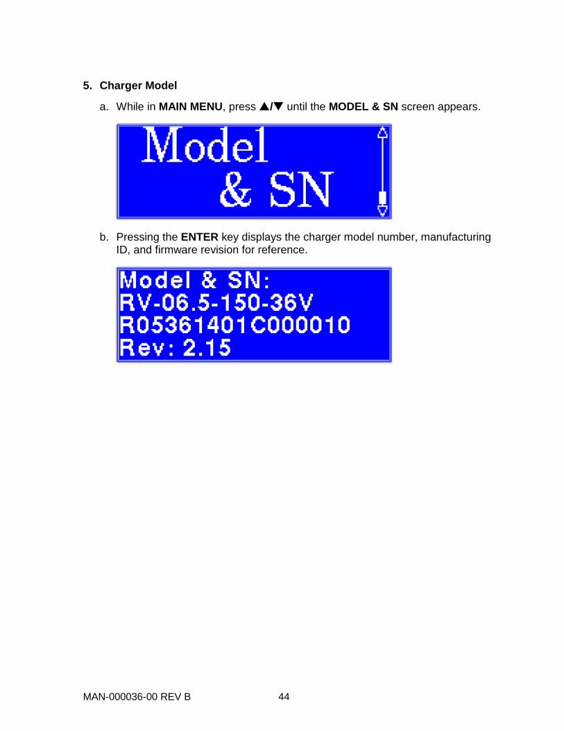
4. Lifetime Summary
a. While in MAIN MENU, press / until the LIFETIME SUMMARY screen appears.
b. Pressing the ENTER key will display a screen summarizing charger lifetime summary stats since installation.
This screen allows verification of charger usage: First charge date and time, total charge hours, amp-hours, and kW-hours, and the total number of cycles completed since installation. This information may be used to compare usage on different chargers.
MAN-000036-00 REV B 44
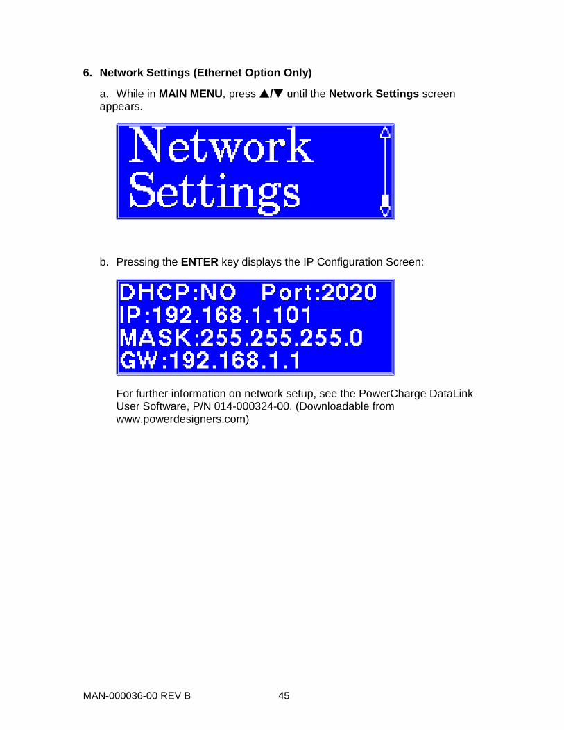
5. Charger Model
a. While in MAIN MENU, press / until the MODEL & SN screen appears.
b. Pressing the ENTER key displays the charger model number, manufacturing ID, and firmware revision for reference.
MAN-000036-00 REV B 45
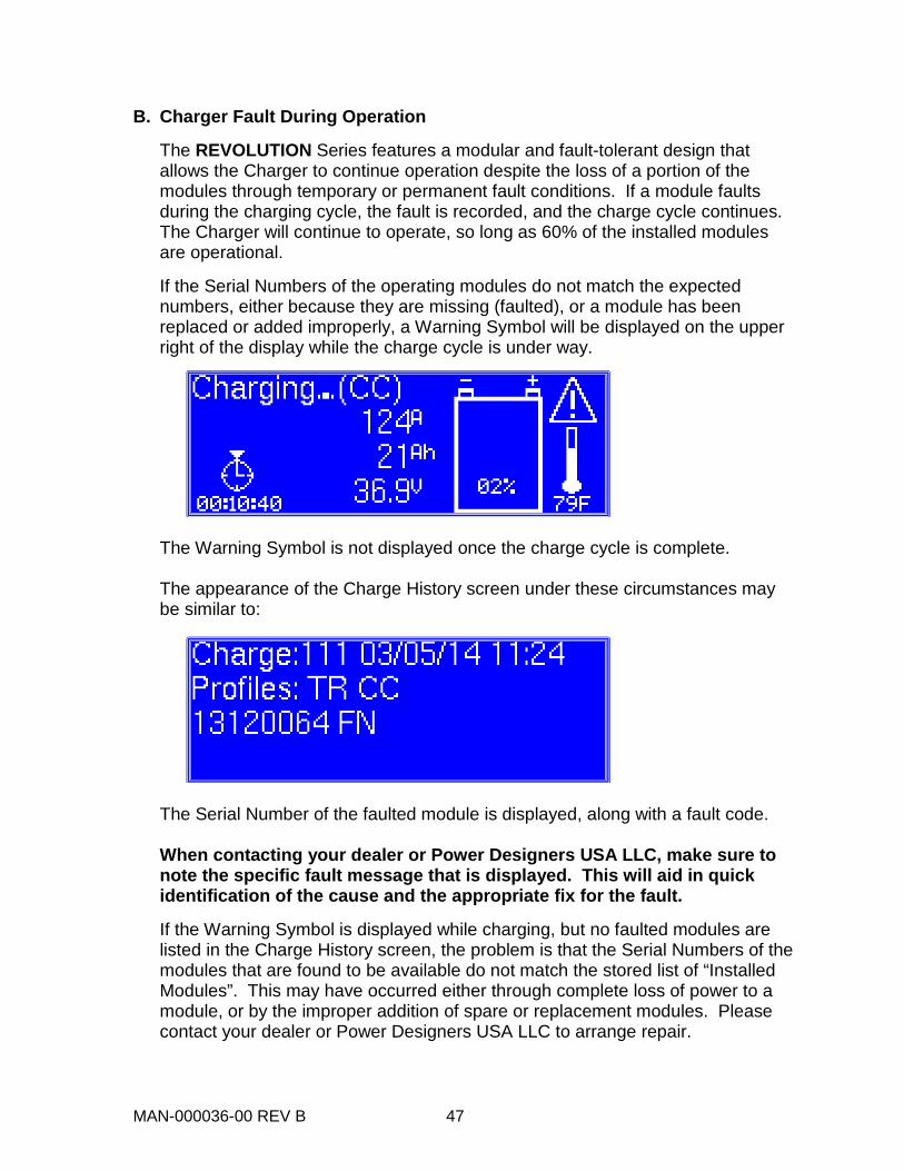
6. Network Settings (Ethernet Option Only)
a. While in MAIN MENU, press / until the Network Settings screen appears.
b. Pressing the ENTER key displays the IP Configuration Screen:
For further information on network setup, see the PowerCharge DataLink User Software, P/N 014-000324-00. (Downloadable from www.powerdesigners.com)

MAN-000036-00 REV B 46
TROUBLESHOOTING
Occasional faults may occur in certain conditions. Please follow the suggested steps.
A. Charger Does Not Power Up
When the charger is first turned on, the LCD should illuminate and display one of the idle mode messages, typically the CONNECT BATTERY screen.
If the LCD is not illuminated after power is applied, perform the following checks:
a. Verify that the service disconnect switch (if provided) and the main panel breaker is in the ON position.
b. Cycle the switch to the OFF position, wait 30 seconds, and then return it to the ON position.
c. If the charger display still does not illuminate, carefully verify the source circuit and wiring to the charger and correct any problems. If appropriate, check that all fuses in the service disconnect switch box on the wall are intact, and also that the supply voltage for all three phases (AC mains line-to-line) is 480 V ± 10%, and matches to 10 VAC or better.
d. If the fault persists, contact the Dealer or Power Designers USA LLC.
DANGEROUS VOLTAGES AND CURRENTS ARE PRESENT IN THE AC MAINS WHEN ENERGIZED. ONLY TRAINED PERSONNEL SHOULD PERFORM THESE CHECKS, USING PROPER EQUIPMENT AND PROCEDURES.
DO NOT ATTEMPT TO SERVICE THE CHARGER!
CAUTION
WARNING
MAN-000036-00 REV B 47
B. Charger Fault During Operation
The REVOLUTION Series features a modular and fault-tolerant design that allows the Charger to continue operation despite the loss of a portion of the modules through temporary or permanent fault conditions. If a module faults during the charging cycle, the fault is recorded, and the charge cycle continues. The Charger will continue to operate, so long as 60% of the installed modules are operational.
If the Serial Numbers of the operating modules do not match the expected numbers, either because they are missing (faulted), or a module has been replaced or added improperly, a Warning Symbol will be displayed on the upper right of the display while the charge cycle is under way.
The Warning Symbol is not displayed once the charge cycle is complete. The appearance of the Charge History screen under these circumstances may be similar to:
The Serial Number of the faulted module is displayed, along with a fault code.
When contacting your dealer or Power Designers USA LLC, make sure to note the specific fault message that is displayed. This will aid in quick identification of the cause and the appropriate fix for the fault.
If the Warning Symbol is displayed while charging, but no faulted modules are listed in the Charge History screen, the problem is that the Serial Numbers of the modules that are found to be available do not match the stored list of “Installed Modules”. This may have occurred either through complete loss of power to a module, or by the improper addition of spare or replacement modules. Please contact your dealer or Power Designers USA LLC to arrange repair.
MAN-000036-00 REV B 48
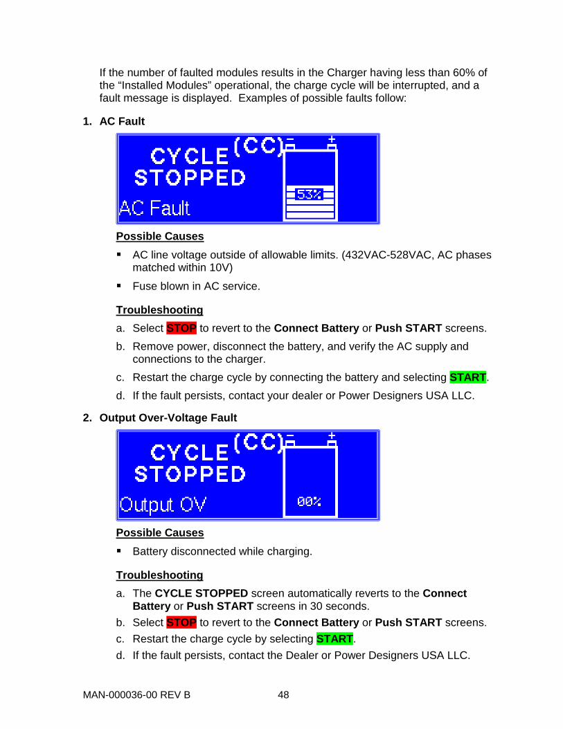
If the number of faulted modules results in the Charger having less than 60% of the “Installed Modules” operational, the charge cycle will be interrupted, and a fault message is displayed. Examples of possible faults follow:
1. AC Fault
Possible Causes AC line voltage outside of allowable limits. (432VAC-528VAC, AC phases
matched within 10V)
Fuse blown in AC service.
Troubleshooting a. Select STOP to revert to the Connect Battery or Push START screens. b. Remove power, disconnect the battery, and verify the AC supply and
connections to the charger. c. Restart the charge cycle by connecting the battery and selecting START. d. If the fault persists, contact your dealer or Power Designers USA LLC.
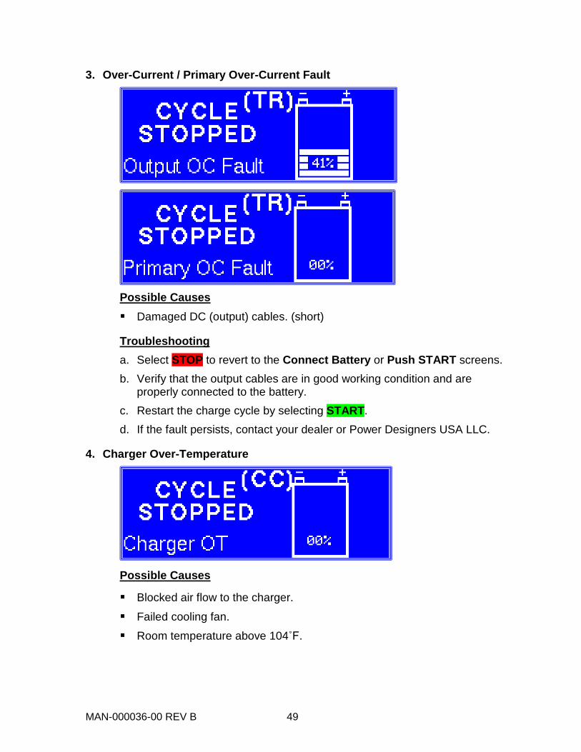
2. Output Over-Voltage Fault
Possible Causes Battery disconnected while charging.
Troubleshooting a. The CYCLE STOPPED screen automatically reverts to the Connect
Battery or Push START screens in 30 seconds. b. Select STOP to revert to the Connect Battery or Push START screens. c. Restart the charge cycle by selecting START. d. If the fault persists, contact the Dealer or Power Designers USA LLC.
MAN-000036-00 REV B 49
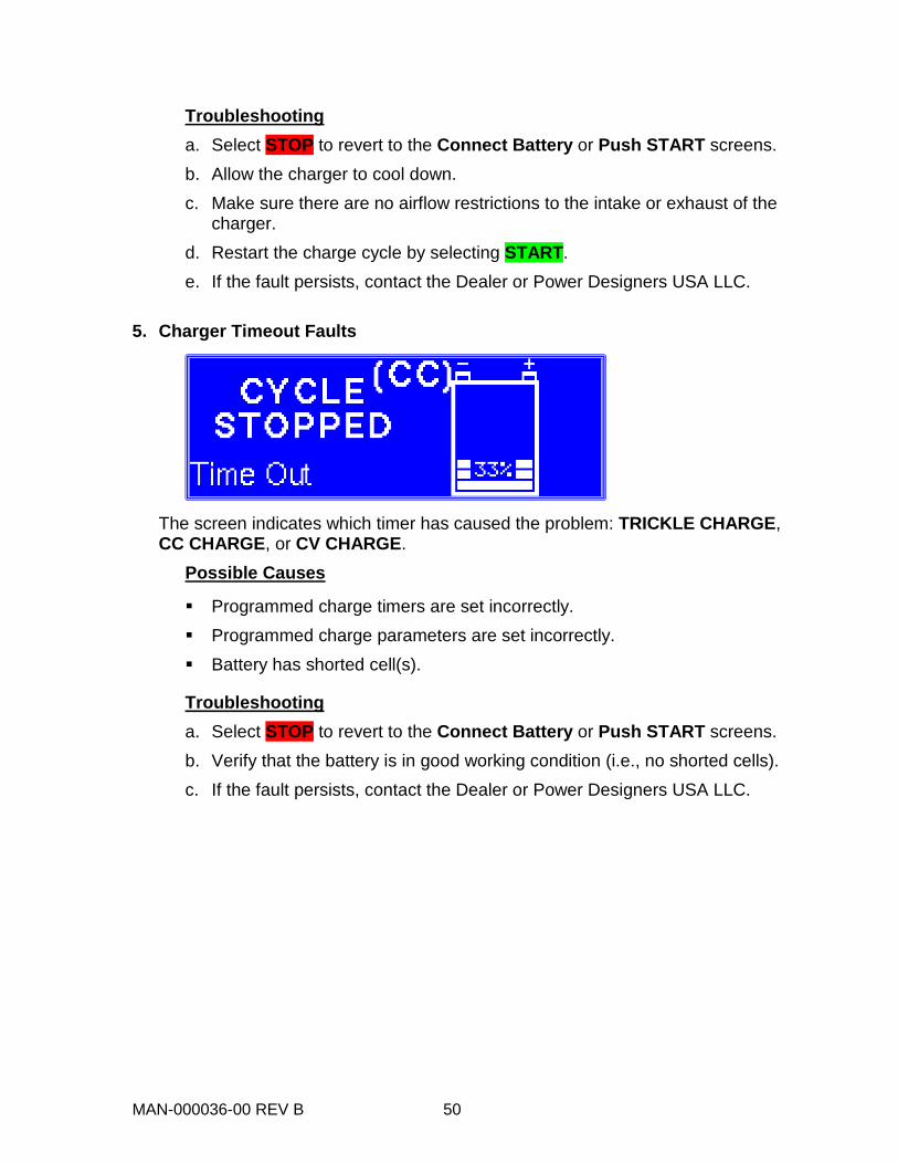
3. Over-Current / Primary Over-Current Fault
Possible Causes Damaged DC (output) cables. (short)
Troubleshooting a. Select STOP to revert to the Connect Battery or Push START screens. b. Verify that the output cables are in good working condition and are
properly connected to the battery. c. Restart the charge cycle by selecting START. d. If the fault persists, contact your dealer or Power Designers USA LLC.
4. Charger Over-Temperature
Possible Causes
Blocked air flow to the charger.
Failed cooling fan.
Room temperature above 104˚F.
MAN-000036-00 REV B 50
Troubleshooting a. Select STOP to revert to the Connect Battery or Push START screens. b. Allow the charger to cool down. c. Make sure there are no airflow restrictions to the intake or exhaust of the
charger. d. Restart the charge cycle by selecting START. e. If the fault persists, contact the Dealer or Power Designers USA LLC.
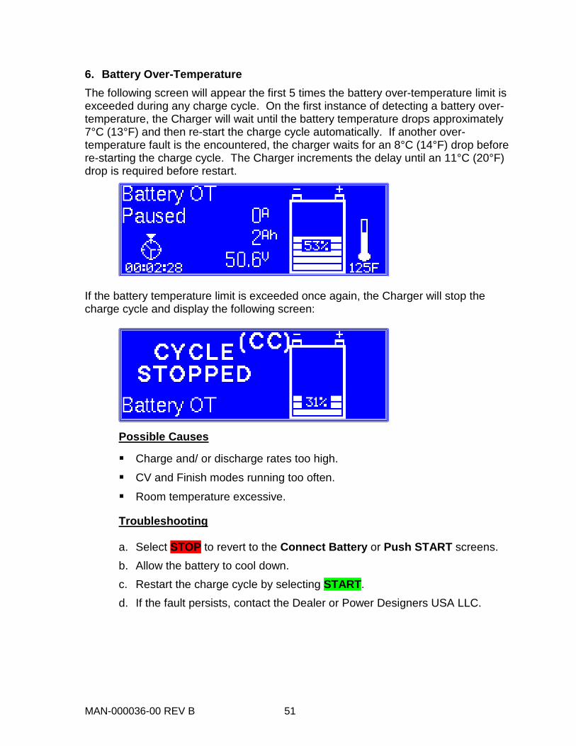
5. Charger Timeout Faults
The screen indicates which timer has caused the problem: TRICKLE CHARGE, CC CHARGE, or CV CHARGE.
Possible Causes
Programmed charge timers are set incorrectly. Programmed charge parameters are set incorrectly. Battery has shorted cell(s).
Troubleshooting a. Select STOP to revert to the Connect Battery or Push START screens. b. Verify that the battery is in good working condition (i.e., no shorted cells). c. If the fault persists, contact the Dealer or Power Designers USA LLC.
MAN-000036-00 REV B 51
6. Battery Over-Temperature The following screen will appear the first 5 times the battery over-temperature limit is exceeded during any charge cycle. On the first instance of detecting a battery over-temperature, the Charger will wait until the battery temperature drops approximately 7°C (13°F) and then re-start the charge cycle automatically. If another over-temperature fault is the encountered, the charger waits for an 8°C (14°F) drop before re-starting the charge cycle. The Charger increments the delay until an 11°C (20°F) drop is required before restart.
If the battery temperature limit is exceeded once again, the Charger will stop the charge cycle and display the following screen:
Possible Causes
Charge and/ or discharge rates too high.
CV and Finish modes running too often.
Room temperature excessive.
Troubleshooting
a. Select STOP to revert to the Connect Battery or Push START screens. b. Allow the battery to cool down. c. Restart the charge cycle by selecting START. d. If the fault persists, contact the Dealer or Power Designers USA LLC.

MAN-000036-00 REV B 52
7. PowerTrac Communication Faults The following screen will appear when the battery is connected and the charger detects the presence of a PowerTrac, but is unable to establish a link. This may be due to a poor or reversed connection of the auxiliary wires.
If the connection to the PowerTrac is lost while a charge cycle is underway, a screen similar to the following will be displayed:
Examining the Charge History will reveal a screen similar to this:
Possible Causes
Worn or broken auxiliary wires or auxiliary contacts
Failure of the PowerTrac
Troubleshooting
a. Inspect connections on both charger and battery sides of the battery connector. Verify auxiliary Wire #1 is connected on the positive (red) side of the battery connector.
b. If the fault persists, contact the Dealer or Power Designers USA LLC.
MAN-000036-00 REV B 53
RETURN MATERIAL PROCESS In the event that the troubleshooting steps included in this manual do not resolve the problem,
a. Record the charger serial number;
b. Call Power Designers USA LLC with a description of the problem.
Power Designers USA LLC will attempt to resolve the problem over the phone. If the issue cannot be resolved in this manner, a Return Material Authorization (RMA) form must be completed and submitted to Power Designers USA LLC. Upon receipt of the completed RMA form, Power Designers USA LLC will issue an RMA number for the return. Based on the serial number of the specific charger(s) and the particular problem encountered, Power Designers USA LLC will either repair or replace the defective components under warranty. For chargers out of warranty, Power Designers USA LLC, upon receipt of the charger and in consideration of a diagnostic fee, will provide a repair estimate. Power Designers USA LLC 4005 Felland Road, Suite 116 Madison, WI 53718 USA www.powerdesigners.com Service Department: 844.263.7050 [email protected]
MAN-000036-00 REV B 54
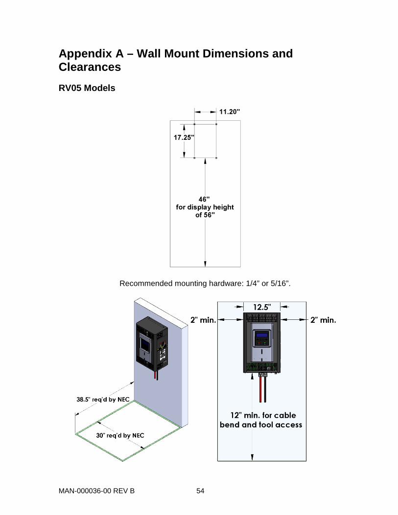
Appendix A – Wall Mount Dimensions and Clearances RV05 Models
Recommended mounting hardware: 1/4” or 5/16”.
MAN-000036-00 REV B 55
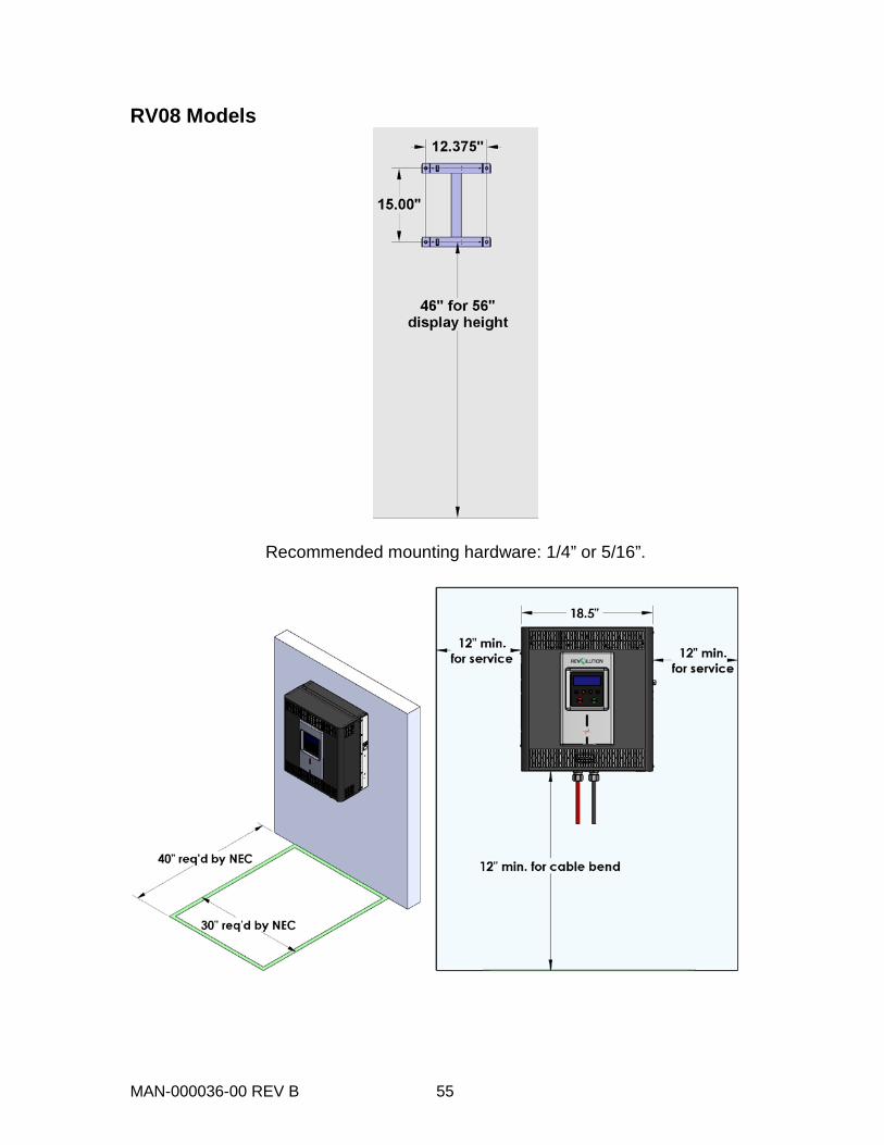
RV08 Models
Recommended mounting hardware: 1/4” or 5/16”.
MAN-000036-00 REV B 56
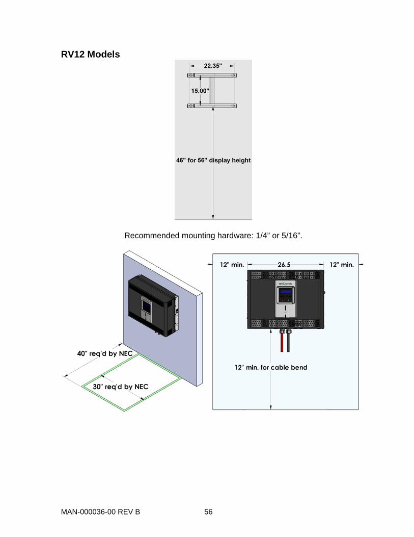
RV12 Models
Recommended mounting hardware: 1/4” or 5/16”.
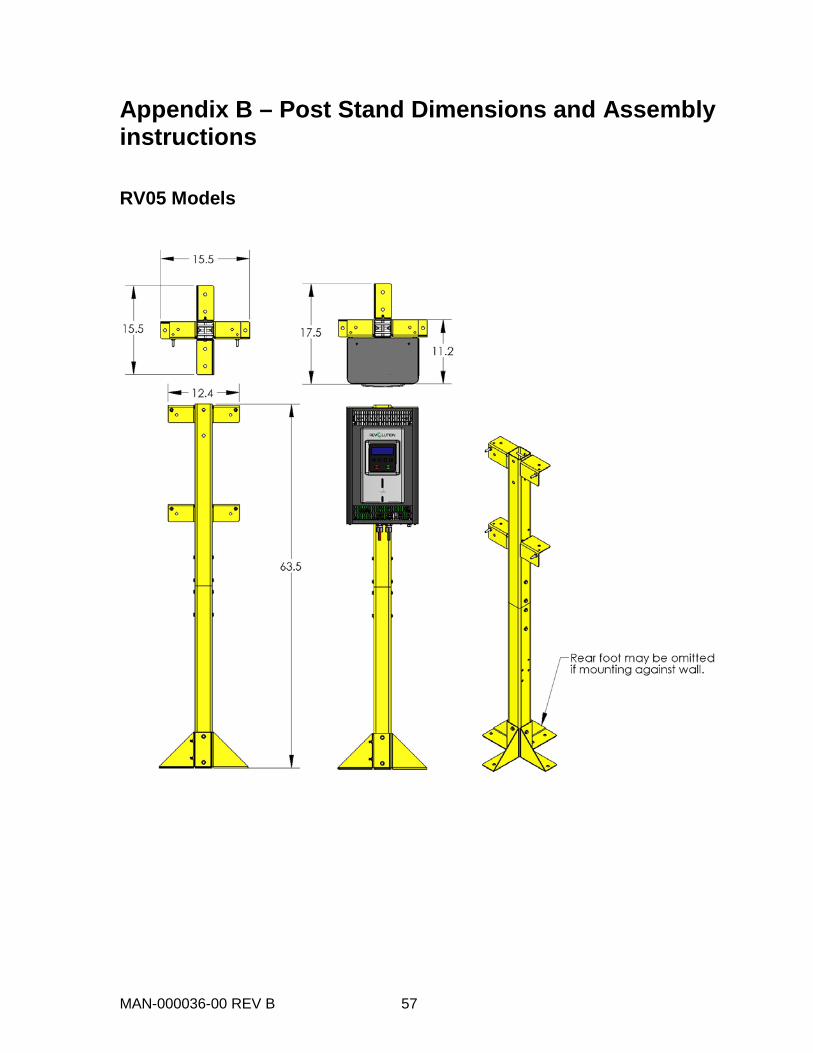
MAN-000036-00 REV B 57
Appendix B – Post Stand Dimensions and Assembly instructions RV05 Models
MAN-000036-00 REV B 58
MAN-000036-00 REV B 59
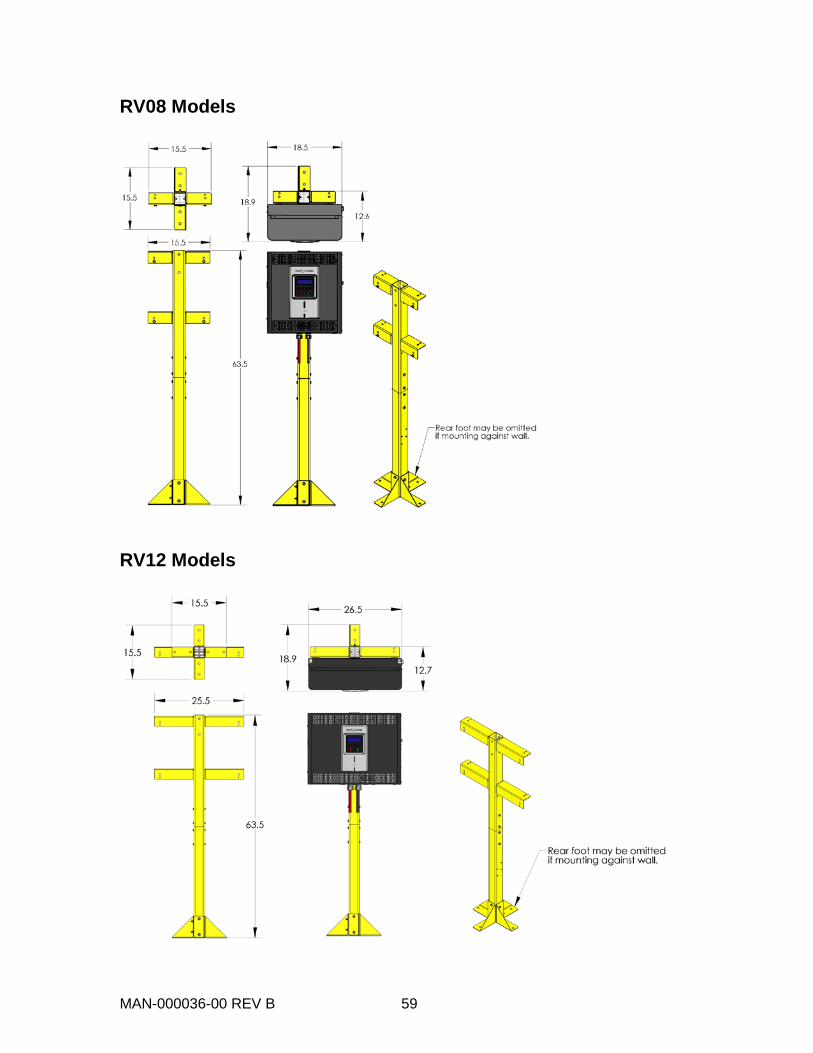
RV08 Models
RV12 Models

MAN-000036-00 REV B 60
MAN-000036-00 REV B 61
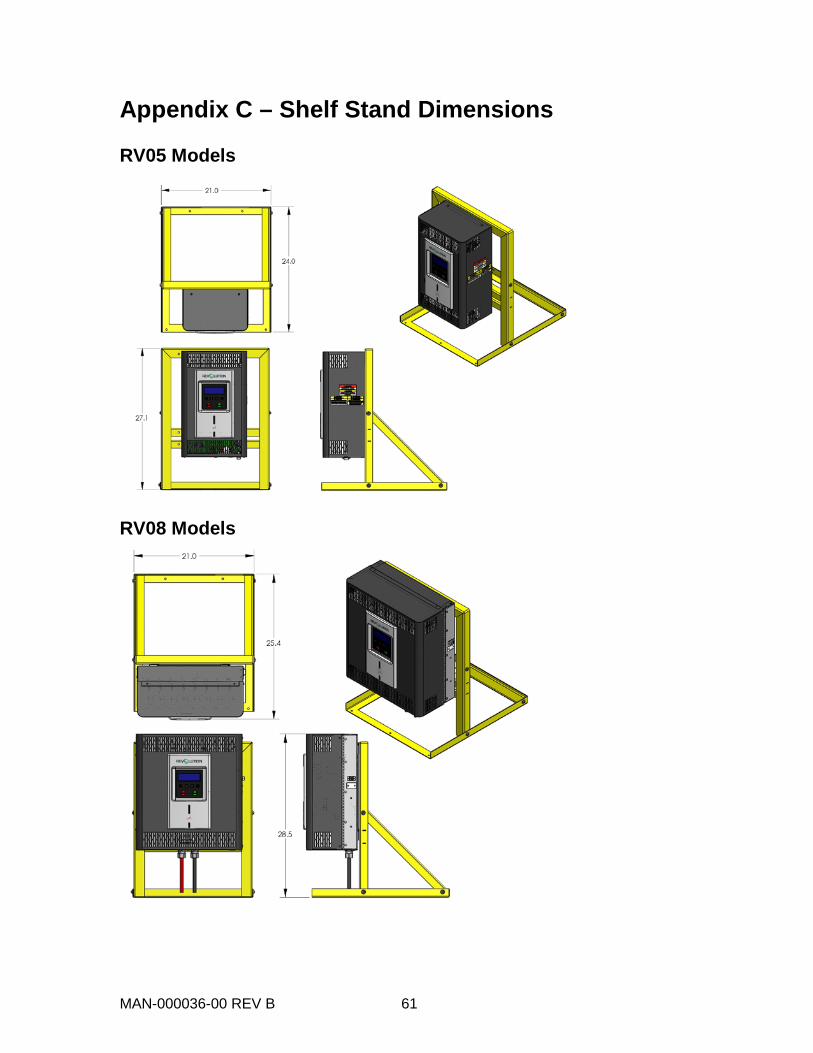
Appendix C – Shelf Stand Dimensions RV05 Models
RV08 Models
MAN-000036-00 REV B 62
Appendix D – Note on Temperature Compensation
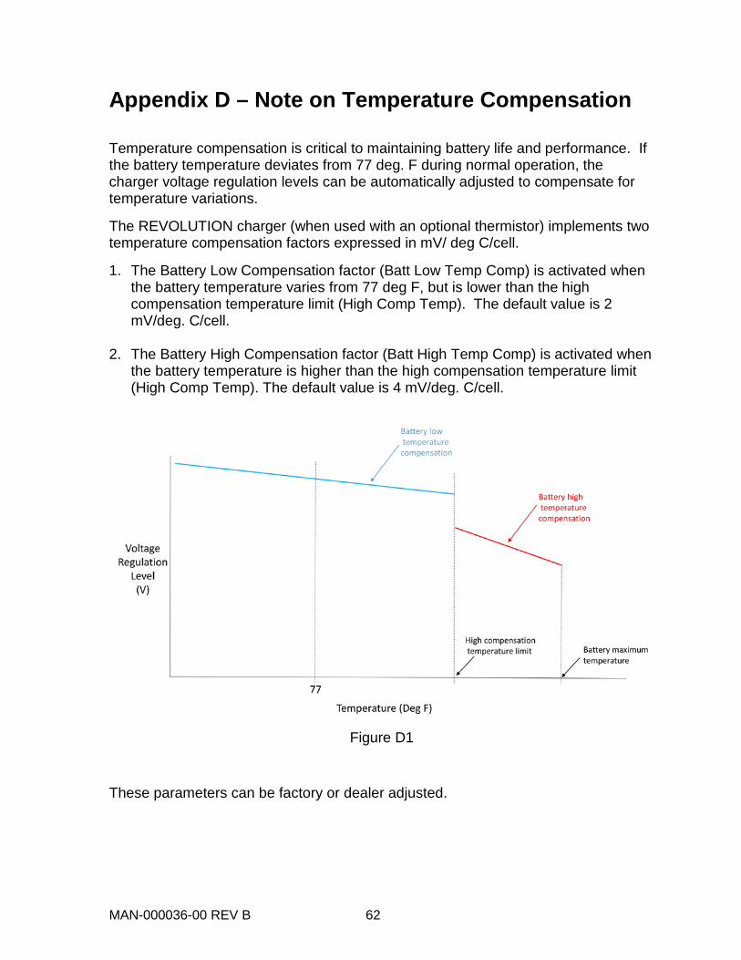
Temperature compensation is critical to maintaining battery life and performance. If the battery temperature deviates from 77 deg. F during normal operation, the charger voltage regulation levels can be automatically adjusted to compensate for temperature variations.
The REVOLUTION charger (when used with an optional thermistor) implements two temperature compensation factors expressed in mV/ deg C/cell.
1. The Battery Low Compensation factor (Batt Low Temp Comp) is activated when the battery temperature varies from 77 deg F, but is lower than the high compensation temperature limit (High Comp Temp). The default value is 2 mV/deg. C/cell.
2. The Battery High Compensation factor (Batt High Temp Comp) is activated when the battery temperature is higher than the high compensation temperature limit (High Comp Temp). The default value is 4 mV/deg. C/cell.
Figure D1
These parameters can be factory or dealer adjusted.

MAN-000036-00 REV B 63
CONTACTING POWER DESIGNERS USA LLC
Power Designers USA LLC 4005 Felland Road, Suite 116
Madison, WI 53718 USA
www.powerdesigners.com
Main Office Phone: 608.231.0450 Main Office Fax: 608.231.9979
Service Department: 844.263.7050 Phones are answered between 8 a.m. and 4 p.m., Monday through Friday Central Time. After-hours calls are answered by voice mail and returned on the next business day. Questions and comments can also be submitted via fax or email.