s ce ),71e-5 prp ya - nrc: home page · s ce ),71e-5 prp / 3 current revision level: prepared by...
TRANSCRIPT

WATTS BAR NUCLEAR PLANT
MAINTENANCE INSTRUCTION
MI-57.1
ANNUAL 6900v SWITCHGEAR INSPECTION
UNITS ELAND 2
S CE ),71E-5 pRp / 3
CURRENT REVISION LEVEL:
Prepared By
Revised By
Submitted By
PORC Review Dat
Approved By
Date Approved
9
John Maddux/David Kirg
Frank J. Tuck -
Supervis/tr
e /7I /
nt an-
8503270453 850323PDR ADOCK 05000390E PDR
Last page of this instruction:
IC
1C1C
'U
1C
iIC
IC
1C
IC
I 1C&1UiC
iC
iC
-- I -j1-aL- 'V-i YA ranch,Compliance UnitComponent Engg & Svs GroupDPSO-WBNDwg & Vendor Manual SupvElect Maint SupvEngg Group SupvEngg Section SupvHealth PhysicistHealth Physics LabInstr Maint SupvInstr ShopMaterials Unit SupvMech Maint SupvMech Unit SupvModifications ManagerOperating Instruction CoordinaOperations SupvOperator Training ClassroomP&S SupvPlant QA SupvPlant Training OfficerPlant Training Shift EngrPower Stores Unit SupvPreop Test SupvPublic SafetyReactor Unit SupvSafety EngrShift Engr's OfficeSupport Svs SupvTech Support CenterUnit 1 Control RmUnit 2 Control RmJohn Raulston, NEB, W1OA63 C-KSite DirectorSite Svs ManagerDesign Svs Manager
4U1 UBB-C
itor
58
OS/6 405
q9
Doc Control Unit, 1520 CST2-CNRCNSRS, 249 A HBB-KPlant Master FilePlant ManagerSupt (O&E)Supt (Maint)Plant Adm Svs SupvASE Duty StationBuilding Services SupvChem LabChem Unit SupvChief, Nuclear Safety StaffChief, Nuclear Training BranchChipf n,--,,4 -- tA ADo- - - n t1I s

WBNMI-57.1Page 1 of 1
HISTORY OF REVISION/REVIEW
REVISED PAGESREASON FOR CURRENT REVISION (INCLUDE
ALL TEMPORARY CHANGE NUMIBERS)7 83/12/13 -3, 4, 31; Delete note after step 6.8 and delete clearance31A added; procedure (Appendix B-pages 35-48) per change35-48 deleted notice 83-50. Incorporate change Nos. 83-128
and 83-165
8 84/09/25 2 Add DPM references that are included ininstruction; two year review
9 All General Revision and added additional signoffs (throughout.
I
L.
L
REV.NO. DATE
I

WBN4MI-57.1Page 1 of 1Revision 9
INDEX
1.0 PURPOSE AND APPLICABILITY
2.0 REFERENCES
3.0 PREREQUISITES
4.0 PRECAUTIONS
5.0 PREPARATION FOR WORK
6.0 PERFORMANCE OF WORK
6A 2 - 6D8 Compartment Inspection
APPENIA-DaaSet
APPENDIX F - 6900V Board Panel ChecklistPage 33 - 6900V Common Board APage 34 - 6900V Common Board BPage 35 - 6900V RCP Board 1APage 36 - 6900V RCP Board 1BPage 37 - 6900V RCP Board 1CPage 38 - 6900V RCP Board IDPage 39 - 6900V RCP Board 2APage 40 - 6900V RCP Board 2BPage 41 - 6900V RCP Board 2CPage 42 -6900V RCP BPage - 900V Shutdown Board A-APage 48 - 6900V Shutdown Board IB-BPage 49 - 6900V Shutdown Board 2A-AP 5 - 6900V Shutdown Board 2B-B
Page 5-690UntBardti
Page 48 - 6900V Start Board BPage 49 - 6900V Unit Board 1APage 50 - 6900v Unit Board 2BPage 51 - 6900V Unit Board ICPage 52 - 6900V Unit Board IDPage 53 -690ov Unit Board 2APage 54 -6900V Unit Board 2BPage 55 -69o)0v Unit Board 2CPage 56 -6900V Unit Board 2DPage 57 - 6900V Common Board CPage 58 - 6900V Common Board D
N0/j
6.,3 T/•~;- 6 q
),6 ,
MILD EQup/v
1
4,
)/
ESpECJ4qL,
G.3, G.)
6S
WBNMI-57.1Page 1 of 24Revision 9
1.0 PURPOSE AND APPLICABILITY
The purpose of this instruction is to provide for an inspection of the6900V switchgear. This instruction should be performed every 18 monthson tne 6 9 00V:common, RCP, start, and unit boards. For these boards thisinstruction can be performed in all modes of operation. This instructionshould be performed during refueling outages at least once every 18 monthsfor the 6900V shutdown boards. For the 6900V shutdown boards, this instruc-tion can be performed in modes 5 and 6 only. This procedure is suitable foruse on all CSSC and non-CSSC systems. Conditions and restraints specifiedin Technical Specifications 3.8.3.1 and 3.8.3.2 are applicable. The 6900Vshutdown boards are the only boards covered by this instruction that arecovered by the Technical Specifications. Steps marked with the symbol ifrequire documentation in the data sheets.
2.0 REFERENCES
2.1 Source Documents
2.1.1 DPM No. N78M6, N74M6, N78M8 (TS.05.05.04.1401)
2.2 Other Documents
2.2.1 Standard Practice, WB7.2.2, Fuses and Fuse Holders
2.2.2 General Electric Switchgear Instruction Manual, GE Magne-Blast Circuit Breaker AM-7.2-500-6 with Metal-Clad Switch-gear M-36. Contract 74-84376.
2.2.3 Tech Specs
3.0 PREREQUISITES
# 3.1 Coordinate the performance of this instruction or any board with theshift engineer. Obtain approval of the shift engineer (SE) or hisdesignated representative to perform this instruction.
# 3.2 For the board being inspected, obtain the necessary clearances forthe performance of this instruction. Steps 6.1 through 6.8 requireboard outage.
3.3 Prepare a data package for use for the board being inspected as follows:
3.3.1 An Appendix A, Data Cover Sheet
3.3.2 The Appendix F, 6900V Board Panel Checksheet, for the boardbeing inspected
3.3.3 An Appendix A, Instrument Data, Sheet
3.3.4 An Appendix A, Replacement Parts, Sheet
3.3.5 An Appendix A, Board Data, Sheet"
2

WBNMI-57.1Page 2 of 24Revision 9
3.0 PREREQUISITES (Continued)
3.3.6 Sufficient copies of Appendix A, Compartment and Breaker DataSheet (one for each panel), to inspect the entire board.
3.4 Notify DPSO for coordination of maintenance on 6900V shutdownboards.
4.0 PRECAUTIONS
4.1 Board feed bus may be energized. Do not open any compartments -except those to be inspected. Do not remove any covers fromenergized bus compartment.
4.2 Loss of power to bus potential transformers will cause tripping.Do not disconnect unless included in clearance.
4.3 Ensure that the bus being inspected is grounded.
#4.4 To preclude the possibility of a maintenance initiated commonmode failure for the shutdown boards, crew personnel and testequipment shall not be the same for A and B trains of the sameunit for consecutive performances of this MI unless the perfor-mance of the board covered by the previous MI has been testedand proven operable for 30 days. Foreman to ensure this.
4.5 CAUTION - Due to high spring tension on the operating mechanism,circuit breakers are potentially dangerous. Craftsmen shouldexercise caution while performing this instruction. Keep yourhands or fingers clear of operating mechanism while breaker ischarged. [5.0 PREPARATION FOR WORK
5.1 Obtain for use in this instruction the following special toolsand instruments. Record this tool number (if applicable) orinstrument, TVA tag number, and calibration due date in AppendixA data sheets. List 575 numbers on all materials drawn fromPower Stores.
5.1.1 6" metal scale (1/64" graduations)5.1.2 Lubricant, GE No. D50H155.1.3 Lubricant, GE No. 50H47
-5.1.4 Lubricant, M035.1.5 Circuit continuity tester5.1.6 12" metal scale (1/64" graduations) or equal L5.1.7 Grounding device5.1.8 100' air hose with nozzle and reducer
# 5.2 If any replacement parts are used, record the "575 number" andthe part number in the appropriate space on the data sheet.
3
N?

WBNMI-57.1Page 3 of 24Revision 9
6.0 PERFORMANCE OF WORK,
NOTE: Steps can be performed in different order to accommodate tagging,etc.
CAUTION: Before any covers are removed or any doors opened whichpermit access to the primary circuits, it is essentialthat a proper clearance is obtained for the work to beperformed.
CAUTION: Before performing 6.1 ensure deenergized.
# 6.1 Meggering to ground and phases of the bus. Minimum acceptancevalue is 7 megohms. Record results in Appendix A.NOTE: If resistance is unsatisfactory and the trouble is found tobe cracking of Thermoplastic Insulation, see MI-57.8 for theproper repair procedure.
# 6.2 Megger between ground and each-phase of the power and boardfeeder cables. Minimum acceptance value is 7 megohms. Alsobridge test between phases of the power cables. Acceptancecriteria shall be that the readings are within ±2 percent ofeach other. Record results in Appendix A "Compartment andBreaker Data Sheet" for each comIartment.
NOTE: When meggering cables to the diesel generators, ground mustbe lifted at the diesel generator building.
II6.2.1 Remove ground connection at diesel generator building.#6.2.2 Remove ground connection from neutral resistor whenmeggering bus work to CSS and USS transformers.
i~6.2.3 Take megger readings.
//6.2.4 Connect grounds lifted in steps 6.2.1 and 6.2.2.# 6.3 Thoroughly clean the equipment including transformer cubicremoving all dust and other accumulations. Visually inspectfilters in bus covers. Replace filters if dirty or deteriorated.# 6.4 Visually inspect the buses and connections carefully for evidence ofoverheating or damage to insulation. Verify in Appendix A.It 6.5 Clean elevating mechanirs
with lubricant GE Company D50H15, or Atlantic Richfield Co. 52,or equal. Verify in Appendix A.
CAUTION: Under no circumstances shall an abrasive be used on silversurfaces.
4
I~r
�1
II

WBNMI-57.1Page 4 of 24Revision 9
6.0 PERFORMANCE OF WORK (Continued)
# 6.6 Check primary disconnecting device contacts for signs of abnormal rwear or overheating. Clean contacts with silver polish if necessary.'Discoloxation of the silvered surfaces is not ordinarily harmful un-less atmospheric conditions cause deposits such as sulphides on thecontacts. Verify in Appendix A.# 6.7 Visually check to see that all bolts in the structure are tight.Verify in Appendix A.
# 6.8 Visually check control wiring for loose connections. Verify inAppendix A.
6.9 Inspect power circuit breakers.
CAUTION: Before any maintenance work is performed, make certainthat all control circuits on the breaker are DEENERGIZEDand that the breaker is removed from the metal-clad unit.Do not work on the breaker or mechanism while in theclosed position unless the prop and trip latch havebeen securely wired or blocked to prevent accidentaltripping. Do not work on the breaker or mechanismwhile the springs are charged unless they are securedin that position by the maintenance spring blockingdevice.
NOTE: If compartment is used for metering, indicate nonapplicable |(N/A) for breaker inspection.
6.9.1 Remove interrupter, see figure 2. L6.9.1.1 The arc chute lifter is assembled to the topplate of the breaker as shown in the referencedfigure using the bolt (5) located between thefront and rear bushings. Before assembling thelifter on the breaker, it is necessary to removethe box barrier. L6.9.1.2 Lower the grappling hooks (6) by turning thehandle (1) until they can be placed over thelifting bolts (9) on the interrupter. Turn the 5handle to raise the hooks until they begin tolift the interrupter.
5
-1?.

I
WBNMI-57.1Page 5 of 24Revision 9
6.0 PERFORMANCE OF WORK (Continued)
6.9.1.3 To remove the interrupter, loosen the two uppersupport bolts (11) and the one lower support bolt(16) using a standard 3/4" wrench. Raise theassembly approximately 3/8" and gently move itfrom side to side until both upper and lower sup-ports are disconnected. Move the trolley (3) ofarc chute lifter towards the rear of the breakerand lower the interrupter to a resting positionon the floor. Support the interrupter from fall-ing over and remove the grappling hooks.
6.9.2
# 6.9.2.1
Check interrupters
The throat area of the interrupter should be cleanedwith sandpaper, if necessary. DO NOT USE EMERYCLOTH OR METALLIC ABRASIVES. All flat areas oneither side of the movable arcing contact travelshould be sanded. Do not attempt to clean theceramic fins of the arc chute sides or throatpieces. Heavily contaminated parts should bereplaced. Verify in Appendix A.
NOTE: Cracks which have formed in the fins of thearc chute are to be expected in ceramicmaterials of this type when subjected tosevere heat of an arc. These cracks do notinterfere with the operation of the devicein any way and should be disregarded.
6

- iiWBNMI-57.1Page 6 of 24Revision 9
6.0 PERFORMANCE OF WORK (Continued)
)-
Assembly BoltsAssembly BoltUpper Pole PiecesRear BraceAssembly BoltSide BraceLower Pole Pieces
8.9.
10.11.12.13.14.
Assembly BoltLower BraceAssembly BoltsUpper SupportsAssembly BoltUpper Interrupter SupportAssembly Bolts
15.16.17.18.19.20.21.
Upper InsulationAssembly BoltsSide ShieldAssembly BoltsLower Interrupter SupportAssembly BoltsAssembly Bolt =
LFIGURE 1
INTERRUPTER ASSEMBLY'
7
I -
f'
I
..i
i.I
1.2.3.4.5.6.7.

WBNMI-57.1Page 7 of 24Revision 9
6.0 PERFORMANCE OF WORK (Continued)
GEI-88763 Magne-Blast Circuit Breaker
I1.2.3.4.5.6.7.8.9.
10.11.12.13.14.15.16.17.18.19.
HandleRear BushingTrolleyArc Chute LifterArc Chute Lifter BoltGrappling HooksUpper Horizontal BarriersUpper Interrupter SupportLifting BoltLower Horizontal BarriersSupporting BoltStationary Arcing ContactsMounting BoltsMovable Arcing ContactArc Chute BraceLower Supporting BoltSupport BracketLower Interrupter SupportInterrupter
FIGURE 2
INTERRUPTER PARTIALLY REMOVEb SHOWINGACCESSIBILITY OF ARCING CONTACTS
8
-I.:
WBNMI-57.1Page 8 of 24Revision 9
6.0 PERFORMANCE OF WORK (Continued)
# 6.9.2.2
# 6.9.2.3
6.9.3
# 6.9.3.1
# 6.9.4
6.9.5
If the arc chute has suffered any mechanical injurydue to dropping or accidental striking, resultingin the actual breaking off of fins, replacement willbe necessary. Small broken corners on the exhaustend of the arc chute sides will not interfere withits performance and can be disregarded. Verify inAppendix A.
The plastisol flexible covering for the pole pieces(3 and 7), figure 1, and the upper mounting support(12) should be inspected for breaks in the insulation.If there are holes or breaks in the insulation, theyshould be repaired or the part replaced. Verify inAppendix A.
Inspect the breaker contacts.
Remove the box barriers, the movable and stationaryprimary contacts, and the movable arcing contactscan be inspected. The stationary arcing contactscan be inspected only after removing the interrupter.If the contacts are burned or pitted, they can bemade smooth with a fine file. Verify in Appendix A.
Inspect all cam, roller, and latch surfaces for anyevidence of damage or excessive wear. Lubricate themechanism as outlined in figures 11 and 13; then usingthe manual charging wrench, open and close the breakerseveral times to make certain that the mechanism oper-ates freely throughout its entire stroke. Verify inAppendix A.
Check the contact adjustments.
CAUTION: Do not work on either the breaker or mechanismunless the closing springs are blocked and theopening springs have been tripped or mechanicallyblocked. This measure is required to preventaccidental closing or tripping.
6.9.5.1 Check arcing contact wipe. See figure 3.
L9
�'.
I
I.
I-
, Ii
l
L
y i-
I
-.

WBNMI-57.1Page 9 of 24Revision 9
6.0 PERYORMANCE OF O (Continued)
LUBRICATION AT ula DISASSEMBLY)
Sleeve bearings-ii~Ltrip shaft, etc.,(Teflon coated bearings)
BO lubrication required
Sleeve beai i Light application of Remove bearings orcrank shaft, driving machine oil SAE 20 or links, clean per in-pawl lever (bronze or SAE 30.
structions and applycast iron) D50H15 lubricant
- aliberallyContact Arm Hinge No lubrication required Wipe clean and applyAssembly, Cup Bearing,
ndOpplLoose rings between D5-H47bushing and contact arm
Roller and needle bear- Light application of Clean per instructionsings machine oil SAE 20 or and repack with D50H15SAB 30.
lubricantGround surfaces, such No lubrication require No luas cams, ratchet teeth,etc. (surfaces coatedwith MoS2)
Ground surfaces, such as Wipe clean and apply Wipe clean and applylatches, rollers, prop D50H47 lubricant
D50H47 lubricant
Silver plated contacts Wipe clean and apply Wipe clean and applyand primary disconnect D50H47 lubricant
D50H47 lubricant
Booster cylinder Do not lubricate
Do not lubricate
FIGURE 13
LUBRICATION CHART
10
PARTS LUBRICATION ATMAINTENANCE PERIOD
ALTERNATE LUBRICATION
No lubrication required

MI-57. 1Page 10 of 24Revision 9
6.0 PERFORMANCE OF WORK (Continued)
-1--
7 7 - IPrimary Contact Wipe
FIGURE 3
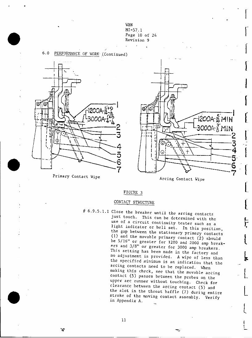
CONTACT STRUCTURE
Arcing Contact Wipe
# 6.9.5.1.1 Close the breaker until the arcing contactsjust touch. This can be determined with theuse of a circuit continuity tester such as alight indicator or bell set. In this position,the gap between the stationary primary contacts(1) and the movable primary contact (2) shouldbe 5/16" or greater for 1200 and 2000 amp break-ers and 3/8" or greater for 3000 amp breakers.This setting has been made in the factory andno adjustment is provided. A wipe of less thanthe specified minimum is an indication that thearcing contacts need to be replaced. Whenmaking this check, see that the movable arcingcontact (5) passes between the probes on theupper arc runner without touching. Check forclearance between the arcing contact (5) andthe slot in the throat baffle (7) during entirestroke of the moving contact assembly. Verifyin Appendix A.
11
I
I,I
I
Ii
WBN

WBNMI-57.1Page 11 of 24Revision 9
6.0 PERFORMANCE OF WORK (Continued)
6. 9.
6.9.6
# 6.9.6
5.2 Check the primary contact wipe. (Refer to figure 3).
# 6.9.5.2.1 When the breaker is closed, the stationaryprimary contacts (1) should rise from 1/4"to 5/16" for 1200 and 2000 amp breakers andfrom 3/16" to 1/4" for 3000 amp breakers.Before checking this dimension, be sure tlemechanism is reset so that the prop pin (4),figure 4, is resting on the prop. To obtainthe proper contact adjustment, open the break-er and referring to figure 5, loosen the checknut (4) and turn the adjusting nut (3). Screw-ing up on the adjusting nut will decrease theprimary contact wipe, down will increase it.Tighten the check nut, close the breaker, andrecheck the wipe. With the primary contactwipe correctly adjusted, the clearance betweenthe contact are (6), figure 3, and buffer block(3) should be 1/16" or greater when the breakeris fully closed. Verify in Appendix A.
Check plunger interlock.
.1 Refer to figure 12. With the breaker in the closedposition, the vertical distance "A" from the top ofthe plunger bolt (1) to the bottom of the breakerlifting rail (3) should be 11-7/32" to 11-11/32".To change this adjustment, add or remove washers (2).Verify in Appendix A.
1. Plunger Bolt 2. Washer 3. Breaker Lifting Rail
FIGURE 12
PLUNGER INTERLOCK
12
-. :
WBNMI-57.1Page 12 of 24Revision 9
6.0 PERFORMANCE OF WORK (Continued)
6.9.7
#- 6.9.7.1
Check the primary contact gap.
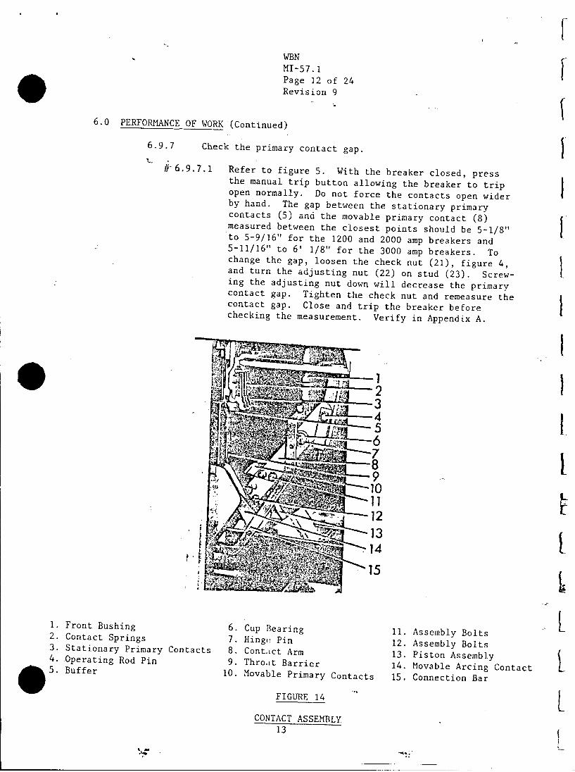
Refer to figure 5. With the breaker closed, pressthe manual trip button allowing the breaker to tripopen normally. Do not force the contacts open widerby hand. The gap between the stationary primarycontacts (5) and the movable primary contact (8)measured between the closest points should be 5-1/8"to 5-9/16" for the 1200 and 2000 amp breakers and5-11/16" to 6' 1/8" for the 3000 amp breakers. Tochange the gap, loosen the check nut (21), figure 4,and turn the adjusting nut (22) on stud (23). Screw-ing the adjusting nut down will decrease the primarycontact gap. Tighten the check nut and remeasure thecontact gap. Close and trip the breaker beforechecking the measurement. Verify in Appendix A.
Front BushingContact SpringsStationary Primary ContactsOperating Rod PinBuffer
6.7.8.9.
10.
Cup BearingHinge PinContict ArmThroat BarrierMovable Primary Contacts
11.12.13.14.15.
Assembly BoltsAssembly BoltsPiston AssemblyMovable Arcing ContactConnection Bar
FIGURE 14
CONTACT ASSEMBLY13
V
I
II-I
1 .2.3.4.5.
. L
I
AI<A:
'L.
WBNMI-57.1Page 10 of 24Revision 9
6.0 PERFORMANCE OF WORK (Continued)
Primary Contact Wipe Arcing Contact I
lI-I
~I.-1200A-IMIN --3000A-81 MN
3 I -=4~,I-- 6 -
Wipe
FIGURE 3
CONTACT STRUCTURE
# 6.9.5.1.1 Close the breaker until the arcing contactsjust touch. This can be determined with theuse of a circuit continuity tester such as alight indicator or bell set. In this position,the gap between the stationary primary contacts(1) and the movable primary contact (2) shouldbe 5/16" or greater for 1200 and 2000 amp break-ers and 3/8" or greater for 3000 amp breakers.This setting has been made in the factory andno adjustment is provided. A wipe of less thanthe specified minimum is an indication that thearcing contacts need to be replaced. Whenmaking this check, see that the movable arcingcontact (5) passes between the probes on theupper arc runner without touching. Check forclearance between the arcing contact (5) andthe slot in the throat baffle (7) duriag entirestroke of the moving contact assembly. Verifyin Appendix A.
11
II
L
L
I
l

WBNMI-57.1Page 13 of 24Revision 9
6.0 PERFORMANCE OF WORK (Continuod)
.0
Main Shaft BearingCrank ShaftCranksProp PinPropCam ShaftCam Shaft BearingCamHandle
10.11.12.13.14.15.16.17.18.
Trip Coil SupportTrip CoilUpper Prop SpringTrip ArmatureLower Prop SpringCam Follower RollerTrip ShaftTrip LatchStop Pin
29.20.21.22.23.24.25.26.
Trip Latch RollerTrip Latch Roller SupportCheck NutStop PlateSfring RodSIringS1ringSpring Guide
FIGURE 4
SECTIONAL SIDE VIEW OF MECHANISM
14
r
1 .2.3.4.5.6.7.8.9.

IWBNMI-57.1Page 14 of 24Revision 9
6.0 PERFORMANCE OF WORK (Continued)
I
I
1.2.3.4.5.6.7.8.
I-
-Ii
Operzting RodOperating Rod PinAdjusting NutCheck NutStationary Primary ContactsYokeContact ArmMovable Primary Contacts
ILl,
IL
FIGURE 5
ADJUSTABLE COUPLING FORMAKING PRIMARY CONTACT
WIPE ADJUSTMENTS
15
"'C An:

WBNMI-57. 1Page 15 of 24Revision 9
6.0 PERFORMANCE OF WORK (Continued)
6.9.8 Check trip latch wipe.
# 6.9.8.1 Refer to figure 4. The wipe of the trip latch (17)on the trip roller (19) shoild be from 3/16" to 1/4".This can be measured by putting a film of grease onthe-latch, closing the breaker part way, and tripping.The mechanism has the proper-trip latch wipe when thelatch rests against the stop pin (18). No adjustmentis provided and a visual inspection is usually allthat is required. If this setting is not correct,look for insufficient travel of the trip shaft (16).Verify in Appendix A.
QC HOLDPOINT
6.9.9 Check trip armature travel.
# 6.9.9.1 Refer to figure 4. The trip armature (13) shouldhave 7/32" to 9/32" travel before the trip latch(17) starts to move. This can be adjusted by movingthe trip coil support (10) and/or by adjusting thetrip armature screw (10), figure 6. Verify inAppendix A.
1.
2'
4.
1. Trip Latch Spring2. Switch Arm3. Spring Discharge Crank
4.5.6.
Cotter PinTrip Coil SupportTrip Coil
7 .8.9.
Mounting BoltsLatch Set ScrewsTrip Latch
10. Trip Arm Screw11. Manual Trip Lever
FIGURE 6
AUXILIARY SWITCH AND TRIP COIL
16
~r

WBNMI-57.1Page 16 of 24Revision 9
6.0 PERFORMANCE OF WORK.(Continued)
6.9.10 Check closing latch wipe.
Latch Checking SwitchSwitch CamSwitch StrikerSwitch Support BoltsSwitch SupportClosing Latch Roller
1t
I
7.8.9.
10.i1 .12.
Power SwitchesClosing LatchClosing Latch ShaftLatch Adjusting ScrewClosing Coil BoltsClosing Latch Spring
13. Latch Monitoring LSwitch
Bracket15. Closing Solenoid -16. Closing Coil Support17. Control Relay I
FIGURE 7
CONTROL MECHANISM
17
1.2.33.4.5.6.
�1;1

WBNMI-57.1Page 17 of 24Revision 9
6.0 PERFORMANCE OF WORK (Continued)
# 6.9.10.1"i 1
Refer to figure 7. The wipe between the closinglatch (8) and roller (6) should be 3/16" to 1/4".If resetting is required, loosen, set, and re-tighten adjustment nut and screw (10). Verifyin Appendix A.
6.9.11 Check closing latch monitoring switch.
# 6.9.11.1 Refer to figure 7. The closing latch must befully reset and the latch monitoring switch (13)operated before the motor will start. When thelatch is fully reset, the clearance between theswitch striker arm and the switch mounting bracket(14) is 1/32" or less, this can be adjusted byblending the striker arm. Verify in Appendix A.
6.9.12 Check the motor and relay switches.
# 6.9.12.1 Refer to figure 7. With the closing springsblocked, rotate the switch cam (2) until theswitch striker (3) has traveled the maximumamount (about 180 degrees rotation of cam).At this point, the clearance between the strikerand the switch support (5) should be 1/32" orless. This can be adjusted by loosening theswitch support mounting bolts (4) and rotatingthe support. Verify in Appendix A.
6.9.13 Check interlock switch wipe.
# 6.9.13.1 Refer to figure 8. With the Positive interlockin the reset, or normal position, the clearancebetween the interlock switch arm (2) and theswitch mounting plate (3) should be 1/32" orless. This can be adjusted by bending the arm.Verify in Appendix A.
18
I -

WBNMI-57.1Page 18 of 24Revision 9
6.0 PERFORMANCE OF WORK (Continued)
Positive Interlock ShaftSwitch ArmSwitch SupportInterlock Switch
5.6.7.
Latch Checking SwitchSwitch ArmTrip Shaft
FIGURE 8
POSITIVE INTERLOCK SWITCH
19
I'
I
l
I1.2.3.4.
I
1,
4-

14
# 6.9.14.1 Refer to figure 9. The driving pawl (8) mustadvance the ratchet wheel (6) sufficiently oneach stroke to allow the latching pawls (2) tofall into the ratchet teeth. This should bechecked with the closing spring load against thedriving members. With the mechanism unblocked,hand charge the closing springs with the manualcharging wrench until they are slightly more thanhalf charged. Slowly rotate the charging wrenchuntil the driving pawl has traveled through itsreturn stroke and check the maximum clearancebetween the pawl and ratchet tooth. Rotate thecharging wrench until the driving pawl has ad-vanced the ratchet tooth to its maximum travel.Now check the clearance between the ratchet toothand the latching pawl. The clearance should beapproximately equal for both the driving latchingpawls and not less than 0.015" in either case.Verify in Appendix A.
6.9.14.2 If adjustment is required for either pawl, thesprings must first be fully charged and blocked.Loosen seven motor support bolts (1), figure 10,and move entire motor assembly to the rear if theclearance is under the minimum at the latchingpawls, and to the front if the clearance is underthe minimum at the driving pawl. Move the motorassembly approximately twice the dimensional in-crease required at the pawl. Be certain the motorassembly is moved straight forward or backward andtighten the one bolt on the right side of themounting frame first to assure proper alignment.After tightening the remaining bolts, the springsshould be released and the clearance again checkedas described above.
20
WBNMI-57.1Page 19 of 24Revision 9
6.0 PERFORMANCE F WORKI (Continued)
6.9.14 Check during pawl adjustment.

WBNMI-57. 1Page 20 of 24Revision 9
6.0 PERFORMANCE OF WORK (Continued)
FIGURE 9
RIGHT SIDE VIEW ML-BOPERATING MECHANI-M
1.2 .3 .4 .5.6.7.8.9.
10.11.12.
Upper Spring PinLatching PawlsPositive Interlock RollerOpening SpringCam ShaftRatchet WheelBearing BlockDriving PawlLower Spring PinDriving Pawl LeverEccentricClosing Spring a
21
iI
If

WBNMI-57.1Page 21 of 24Revision 9
6.0 PERFORMANCE OF WORK (Continued)
1.2.3.4.5.6.7.8.9.
Mounting BoltsManual Close ButtonMotorRetaining RingEccentricRetaining RingHex Charging StudDriving LinkMotor Support
FIGURE 10
DRIVING ELEMENTS '
22

WBNMI-57.1Page 22 of 24Revision 9
6.0 PERFORMANCE OF WORK (Continued)
I
3
/ --
8Y AN\
Switch SupportLatch Checking SwitchSwitch ArmTrip LatchReset Pin StopLatch RollerLatch Roller LinkLatch Roller Pin
1 .2.3.4.5.6.7.8.9.
10.11.12.13.
FIGURE 11
LATCH CHECKING SWITCH
Upper Arc Runner SpacersUpper Arc Runner AssemblyBlowout CoreBlowout CoilUpper Arc RunnerArc Chute SideUpper InsulationThroat CoolerLower Arc RunnerLower InsulationLower Arc Runner SpacersLower Arc Runner AssemblyLower Coil Connection
FIGURE 15
INTERRUPTER ASSEMBLY
23
6
1 .2.3.4.5.6.7.8.
L-I
l
Ll
L
-

WBNMI-57.1Page 23 of 24Revision
9
6.0 PERFORfMANCE OF WORK (Continued)
- 9 1 Inspect the stationary auxiliary switches for corct ~alignment and loose mounting bolts. Verify in Appendi< -- A./
# 6.9.16 Inspect brushes on charging motor for wear and looseholders. Verify in Appendix A.
g .9.17 Visually inspect for loose nuts, bolts, and loose ort ~damaged set screws or other locking devices. All cam,)> ~roller, and and latch surfaces should be inspected for << any evidence of damage or excessive wear. Verify inAd ~~Appendix A.,-----~
# 6.9.18 Check the control wiring for tightness of connectionsand damaged insulation. Verify in Appendix A.
6.9.19 Reassemble the interrupter. (Reference figure 2.)
6.9.19.1 To reassemble the interrupter to the breaker, restthe lower interrupter support (18) on the supportbracket (17). Slide the arc chute forward, lift-ing it slightly to engage the supporting bolts (11)in the slots of the upper interrupter support (8).Check to assure that the upper insulation (15),figure 1, is properly positioned within the barriersuspended from the stationary contact support (9),figure 14.
6.9.19.2 Tighten the supporting bolts (11 and 16), figure 2 untilsnug. These bolts serve as both the electrical andmechanical connections between the bushings and the arcrunners within the interrupter. Check that the movablearcing contact (14) passes between the probes on theupper arc runner (5), figure 15, without touching.# 6.9.20 Apply a thin coat of contact lubricant D50H47 to breakerstuds for lubrication. Verify in Appendix A.
# 6.10 Electrically test operate breaker. Verify proper operation inAppendix A.
¢ .11 Visually inspect relays in compartment being inspected. Cleancontacts with a flexible burnishing tool if necessary. Do notuse knives, files, abrasive paper or cloth of any kind to clean> relay contacts. Note any unusual discrepancies in Appendix A< ~data sheets.
6.12 Visual inspection of the 30 amp fuse holders in the compartmentbeing inspected.
24
"A.-.2 ,:.

WB NMI-57.1Page 24 of 24Revision 9
6.0 PERFOR.M.NCE OF WORK (Continued)
6.12.1 Ensure the fuse cover is firmly engaged in the fuseholder base.
6.!2.2 Ensure the male contact probe in the fuse cover is at a900 angle to the cover. I
# 6.12.3 Adjust the contact clips in 'he fuse holder base to a gapof approximately 0.062" (1/16") with a greased feeler gage.
6.12.4 Ensure the contact clips are aligned to receive the malecontact probes. f
6.12.5 Wipe the contact probes and clips clean and apply a thincoat of contact lubricant D50H47 to the probes.
6.12.6 Insert and remove the fuse holder from the fuse holderbase. Check for contact wipe along at least 75 percentof the length of the contact clip. Note any discrep-ancies in Appendix A data sheets.
# 6.13 Replace breaker to the appropriate compartment.
# 6.14 Remove tools, spare parts, and all potential fire hazardmaterials, such as rags, flammable and combustible liquids,clothing and plastic, and properly dispose of them. Craftforemen shall perform a final inspection of the work area {to ensure that all tools, spare parts, and potential firehazard materials, such as rage, flammable and combustibleliquids, and plastic have been removed and properly dis-posed. The craft foreman shall verify by signing the datasheet in Appendix A.
# 6.15 Release Hold Order to shift engineer.
# 6.16 Ensure that Appendix A is complete.
# 6.17 Notify the shift engineer at the completion of this Instruction. (NOTE: Since breaker is operated electrically, no additional post
maintenance inspection is necessary. L
25

WBNMI-57.1Appendix APage 1 of 7Revision 9
DATA COVER SHEET
Annual 6900V Switchgear Inspection
Board Name
Performed By:
Performed By: -_._-
Inspection Completed
Electrician Foreman
Reviewed and Approved
Board Number
Date:
Date:
Date:
General Foreman
Standard maintenance appendixes B, C, D, and E are not used in this instruction.Standard maintenance appendixes A and F are attached and should be usedin this instruction.
All calibrated instruments and tools utilized in this instruction on CSSC boardshave been recorded in the CSSC Instrument and Tool Log.
Maintenance Personnel
Results Reviewed and Approved
Electrical Engineer
PQA Review
PQA Supervisor
Date
Date
Date
RETURN TO ELECTRICAL IMAINTENANCE SECTION
Remarks:
26
n. IF -

WBNMI-57.1Appendix APage 2 of 7Revision 9.
3.1 Approval to perform this instruction.
.__Test Equipment
I.--- I
I
TVA Tag No.
Shift Engineer Date
Calibration Due Date
27
Date

WBNMI-57.1Appendix APage 3 of 7Revision 9
BOARD DATA SHEET
NOTE: Numbered steps correspond to steps in the Work Performance section of this MI.
3.2 Necessary clearances installed
Operations Date
Foreman Date
:4.4 Common mode requirements met
Foreman Date
5.2 REPLACEMENT PARTS
Part Name
61 Bs .
6.1 us mggertes
Part No. "575" No.
A0 to GroundB0 to GroundC0 to Ground
- megohms- megohms- megohms
Data Recorded by /
Acceptance Criteria:
All readings must be >7 megohms.
NOTE: If the acceptance criteria are not met, notify the foreman.
NOTE: Data for steps 6.2 through 6.13 will be recorded on the Appendix A,Compartment and Breaker Data Sheet.
28

WBNMI-57. 1Appendix APage 4 of 7Revision 9
COMPARTMENT AND BREAKER DATA SHEETt.
Board Number Compartment Number Breaker Serial Number
4 NOTE: There will be one copy of the Compartment--and Breaker--Data Sheet foreach compartment of the board being inspected-(except for future compart-ments).
| Step No.____
6.2 Power Cable and Board Feeder Meggar Test-
Test Valuef A0 to B0 - ohms
B0 to C0 ohms
C.0 to A0 ohms o--h.msA0 to Ground _ ''''' megohms
B0 to Ground __ megohmsr CWto Ground ------. megohms. .
6.2.L .GroundLremoved at Diiesel.,Generator....-.Building / /
Craftsman Date Craftsman Date6.2.2 Ground removed at neutral resistor
/ /__ _ _ _ _ _ _ __ _ _ _ _ _ _ _
Craftsman Date Craftsman te6.2.4 Connect grounds lifted in step 6.2.1 and 6.2.2
-ECraftsman Date Craftsman DateData Recorded by
Date
Acceptance Criteria: OK , not OKInitials Initials
All megger readings must be >7 megohms. Bridge test readings within±2 percent.
NOTE: If the acceptance criteria are not met, notify the foreman.
29
WBNMI-57.1Appendix APage 5 of 7Revision 9
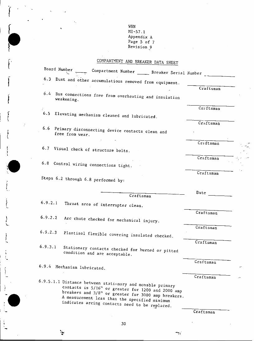
COMPARTMENT AND BREAKER DATA SHEETBoard Number Compartment Number Breaker Serial Number
6.3 Dust and other accumulations removed from equipment. -Craftsman
6.4 Bus connections free from overheating and insulationweakening.
Croftsman6.5 Elevating mechanism cleaned and lubricated.
Craiftsman6.6 Primary disconnecting device contacts clean andfree from wear.
Craftsman6.7 Visual check of structure bolts.
Craftsman6.8 Control wiring connections tight.
CraftsmanSteps 6.2 through 6.8 performed by:
DateCraftsman
6.9.2.1 Throat area of interrupter clean.
Craftsman6.9.2.2 Arc chute checked for mechanical injury. -
Craftsman6.9.2.3 Plastisol flexible covering insulated checked.
Craftsman6.9.3.1 Stationary contacts checked for burned or pittedcondition and are acceptable.
Craftsman6.9.4 Mechanism lubricated.
Craftsman6.9.5.1.1 Distance between stationary and movable primary
contacts is 5/16" or greater for 1200 and 2000 ampbreakers and 3/8" or greater for 3000 amp breakers.A measurement less than the specified minimumindicates arcing contacts need to be replaced.
Cra-ftsman
30

WBNMI-57. 1Appendix APage 6 of 7Revision 9
COMPARTMENT AND BREAKER DATA SHEET
Board Number Compartment Number Breaker Serial Number
6.9.5.2.1 Primary contact wipe is 1/4" to 5/16" for 1200and 2000 amp breakers and from 3/16" to 1/4" for3000 amp breakers.
Cl
6.9.6.1 Plunger interlock is 11-7/32" to 11-11/32"
C)6.9.7.1 Primary contact gap is 5-1/8" to 5-9/16" for1200 to 2000 amp and 5-11/16" to 6-1/8" forthe 3000 amp (start boards).
Cr6.9.8.1 Trip latch wipe is 3/16" to 1/4" with triplatch resting against stop pin.
Cr
QC HOLDPOINT
QC Inspector6.9.9.1 Trip armature travel is 7/32" to 9/32".
Cr,6.9.10.1 Closing latch wipe is 3-/16" to 1/4"
Crc6.9.11.1 Closing latch monitoring switch has a maximum
clearance of 1/32".
Cre6.9.12.1 Motor and relay has maximum clearance of 1/32".
Cra'.9.13.1 Interlock switch has maximum clearance of 1/32".
Cra.9.14.1 Driving and latching pawl has minimum clearance
to ratchet teeth are 0.015".
6.9.15
6.9.16
6.9.17
Stationary auxiliary switches aligned.
Charging motor brushes acceptable.
Visually inspect mechanism for loose partsand wear.
iraftsman
:aftsman
a Etsman
aftsman
Date
aftsman
.3- . -s ~
iftsman
-ftsman
Tftsma`n
Craftsman
Cra ftsman
Craftsman
Craftsman
31
6
6
;

WBNMI-57.1Appendix APage 7 of 7Revision 9
COMPARTMENT AND BREAKER DATA SHEET
Board Number Compartment Number Breaker Serial Number
6.9.18 Visually inspect control wiring.
Craftsman
6.9.20 Breaker studs lubricated.
Craftsman
:6.10 Breaker electrically operated.
Craftsman
6.11 Relays visually inspected.
Craftsman
6.12.3 Fuse contact clips adjusted.
Craftsman
6.13 Breaker replaced.
Craftsman
REMARKS:
6.14 All tools, spare parts, and potential fire hazard materials, such asrags, flammable and combustible liquids, and plastic have bean removedfrom the work area and been properly disposed of.
Verified by /Craft Foreman Date
6.15 Hold Order released and returned to normal.
Electrician Foreman Date Operations Date
6.16 Appendix A completed and attached.
Electrician Foreman Date
6.17 Shift engineer notified at completion of this instruction.
Shift Engineer Date
32

WBNMI-57. 1Appendix FPage 1 of 26Revision.9
6900V BOARD PANEL CHECKLIST
COMMON BOARD A
PANEL NO. DESCRIPTION COMPLETION CHECKLISTCOMPARTMENT BREAKER1 Alternate Supply Breaker No. 1126
from Unit SS Bus 2B2 Auxiliary Panel
N/A3 Auxiliary Bldg Chiller A, El 7374 Future 161kV Swyd Power Cab Xfmr,
500-kV Swyd Power Cabinet Transfer 15 480V Turbine Bldg Common Bd Xfmr A6 480V Auxiliary Bldg Main Bd Xfmr A7 480V Service Bldg Main Bd Xfmr A8 480V Common Emergency Transformer
-Feeder-A-- {Norma-)- - -
9 480V Intake Pumping Sta Main Bd Xfmr A10 Turbine Bldg Lighting Bd Bus A11 Aux Bldg Lighting Board Bus A12 Normal Supply Breaker No. 1526 from
Start Bus A
13 Auxiliary Panel14 480V CCW Pumping Sta Main bd Xfmr A N/A15 Spare
N/A
33

WBNMI-57.1Appendix FPage 2 of 26Revision 9
6900V BOARD PANEL CHECKLIST
COMMON BOARD B
PANEL NO. DESCRIPTIONCIT
COMPARTHENT BREAKERi ------ Auxiliary Panel -R N/A2 Normal Supply Breaker No. 1626 from
Start Bus B - --3 ---Auxiliary Bldg Chiller B, El 737-4 Future 161kV Swyd Power Cab Xfmr,
500-kV Swyd Power Cabinet Xfmr 15 =480V Turbine Bldg Common Board Xfmr B6 '480V Auxiliary Bldg Main Bd Xfmr A7- - 480V'Service -Bldg Nain Bd Xfmr A
---8----- 480V Common Emergency TransformerFeeder A (Normal)
-9= -480V Intake Pumping Sta Main Bd Xfmr A10 Turbine Bldg'Lighting Bd Bus A11 Aux Bldg Lighting Board Bus A12 Auxiliary Panel
N/A13 Alternate Supply Breaker No. 1216from Unit SS Bus 2A
14 480V CCW Pumping Sta Main Bd Xfmr A N/A15 -- Environental Data Station
-------.--
34

WBNMI-57.1Appendix FPage 3 of 26Revision 9
6900V BOARD PANEL CHECKLIST
RCP BOARD IA
. COMPLETION CHECKLISTPANEL NO. DESCRIPTIONCOMPARTMENT BREAKER1 Alt Feeder Bkr 2522
o--2 RCP No. 1
--3- -- Normal Feeder Breaker 21124 Auxiliary Panel
N/A
35
a?:

WBNMI-57.1Appendix FPage 4 of 26Revision 9
6900V BOARD PANEL CHECKLIST
RCP BOARD 1B
PANEL NO. DESCRIPTION OMPLETION CHECKLISTCOMPARTMENT BREAKER1 Normal Feeder Breaker 2114
2 RCP No. 2
3 Alternate Feeder Breaker 2622
36

WBNMI-57.1Appendix FPage 5 of 26Revision 9
6900V BOARDf PANEL CHECKLIST
RCP BOARD IC
COMPLETION CHECKLISTPANEL NO. DESCRIPTIONCOMPA.RTMENT BREAKER1 Normal Feeder Breaker 2122
2 RCP No. 3
3 Alternate Feeder Breaker 2524
37

WBNMI-57.IAppendix FPage 6 of 26Revision 9
6900V BOARD PANEL CHECKLIST
RCP BOARD ID
COMPLETION CHECKLISTPANEL NO. DESCRIPTION COMPARTMENT BREAKER
1 Auxiliary Panel- N/A
2 Normal Feeder Breaker 2124
3 RCP No. 3
4 Alternate Feeder Breaker 2624
5 Auxiliary Panel N/A
38

WBNMI-57. 1Appendix FPage 7 of 26Revision.9
--6900V BOARD-PANEL--CHECKLIST
RCP BOARD 2A
PANEL NO. DESCRIPTION COMPLETION CHECKLISTr COMPARTMENT BREAKERAlternate Feeder Breaker 2532
2 RP No. 13 Normal Feeder Breaker 2212
N4 Auxiliary Panel/A
$ , - - - -, - -,N- A
S
S
39

WBN'MI-57.1
Appendix FPage 8 of 26Revision 9
j 6900V BOARD PANEL CHECKLIST
RCP BOARD 2B
-COMPLETION CHECKLISTPANEL NO. DESCRIPTION C ECK,, - COMPARTMENT BREAKERNormal Feeder Breaker 2214
2 RCP No. 23 Alternate Feeder Breaker 2632
S
S1 -- -- -40
A!:

WBN'MI-57.1Appendix FPage 9 of 26Revision 9
6900V BOARD PANEL CHECKLIST
RCP BOARD 2C
PANEL NO. DESCRIPTION CCMPLETION CHECKLISTN NCOMPARTMENT
BREAKER1 Normal Feeder Breaker 22222 RCP No. 33 Alternate Feeder Breaker 2534
41
. :

-'A.
WBNMI-57.1Appendix FPage 10 of 26Revision 9
I-- 6900V BOARD PANEL CHECKLIST
RCP BOARD ID
PANEL NO. DESCRIPTION COMPLETION CHECKLISTCOMPARTMENT BREAKER1 Auxiliary Panel
N/A
-N -
2 Normal Feeder Breaker 22243 RCP No. 4
.4 Alternate Feeder Breaker 2634;5 Auxiliary Panel
N/A
S
S-42.

WBNMI-57.1Appendix FPage 11 of 26Revision 9
690fV-3OARD-PANELCHECK-I S-T
SHUTDOWN BOARD 1A-A
COMPLETION CHECKLISTPANEL NO. DESCRIPTION -- --- COMPARTHENT -BREAKER0 Relay (RCP) N/A
Alt #2 Sup from CSST D Bar 1812 N/A2 Auxiliary Panel N/A3 480V Shutdown Xfmr 1Al-A
4 480V Shutdown Xfmr 1A2-A
5 480V Shutdown Xfmr 1A-A
6 Emergency Sup from D-G 1A-A7 Auxiliary Panel N/A8 Essential Raw Cooling Water Pump A-A9 Essential Raw Cooling Water Pump B-A
10 Auxiliary Feedwater Pump 1A-A
11 Normal Sup from 6.9 Unit Board 1B12 Auxiliary Panel N/A
13 Containment Spray Pump 1A-A
14 Residual Heat Removal Pump 1A-A
15 Safety Injection Pump 1A-A
16 Alt #1 Sup From CSST C Bkr 171217 Auxiliary Panel N/A18 Centrifugal Charging Pump 1A-A19 Spare N/A20 Pressurizer Htr Backup Group Xfmr 1A-A21 Pressurizer Htr Control Group Xfmr ID
43

WBNtMI-57. 1Appendix FPage 12 of 26Revision.9
f 6900V BOARD PANEL CHECKLIST
SHUTDOWN BOA ID lB-B
PANEL NO. DESCRIPTION MCOMP MENT BREAKER1 Alt #2 Sup From CSST C Bkr 2714CPATHN
BRKE| 2 ~Auxiliary Panel /
1N/A
3 480V Shutdown Xfmr iBI-B4 480V Shutdown Xfrmr 1B2-B5 480V Shutdown Xfmr lB-B
i6 Emer Sup From D-G lB-B7 Auxiliary Panel
/8 Essential Raw Cooling Water Pump F-B9 Essential Raw Cooling Water Pump E-B
10 Aux Feedwater Pump lB-B11 Nor Sup From 6.9 Unit Board IC2 Auxiliary Pa-el -
N/AF 13 Containment Spray Pump lB-B14 Residual Heat Removal Pump 1B-B15 Safety Injection Pump lB-B16 Alt #1 Sup from CSST D Bkr 281417 Auxiliary Panel18 Centrifugal Charging Pump lB-B
-19 Spare N/
20 Pressurizer Htr Backup Group Xfmr lB-B21 Pressurizer Htr Backup Group iC
44I,:.

. @ WBNvMI-57. 1Appendix FPage 13 of 26Revision 9
6900V BOARD PANEL CHECKLISTt -- SHUTDOWN BOARL 2A9-A
DESCRIPTION
IONCECKLIST04 Relay (RCP) --- -COM1PARTM~ENT BREANERAlt
N/A
1 Alt //2 Sup From CSST D Bkr 1812*2 Auxiliary Panel -- -,
/3 480V Shutdown Xfmr 2A1-AN/A.4 480V Shutdown Xfmr 2A2-A
5 48OV Shutdown Xfmr 2A-A6 Emer Sup from D-G 2A-A7 0 Auxiliary Panel8 Essential Raw Cooling Water Pump D-A9 Essential Raw Cooling Water Pump C-A
10 Auxiliary Feedwater Pump 2A-A--- -11 Nor Sup from 6.9 Unit Board 2B12 Auxiliary Panel
'-13 Containment Spray Pump 2A-A /
o n t N / A* 14 Residual Heat Removal Pump 2A-A
15 Safety Injection Pump 2A-A16 Alt #1 Sup From CSST C Bkr 1712
i17 AxiayPanel18 Centrifugal Charging Pump 2A-A
NA19 Temp Emer FDR to 0-BD-228-l & 220 Pressurizer Htr Backup Group Xfmr 2A-A21 Pressurizer Htr Control Group Xfmr 2D
-------.----
45

WBNMI-57.1Appendix FPage 14 of 26Revision 9
6900V BOARD PANEL CHECKLIST-SHUTDOWN BOARD 2B-B
CO4PLETION CHECKLISTPANEL NO. DESCRIPTION COMPARTMENT BREAKER1 Alt #2 Sup From CSST C Bkr 27142 Auxiliary Panel
N/A3 480V Shutdown Xfmr 2B1-B
4 480V Shutdown Xfmr 2B2-B
5 480V Shutdown xfmr 2B-B
6 Emer Sup from D-G 2B-B
7 Auxiliary Panel N/A
8 Essential Raw Cooling Water Pump H-B9 Essential Raw Cooling Water Pump G-B
10 Aux Feedwater Pump 2B-B
11 Nor Sup from 6.9 Unit Bd 2C
12 Auxiliary Panel N/A
13 Containment Spray Pump 2B-B
14 Residual Heat Removal Pump 2B-B
15 Safety Injection Pump 2B-B
16 Alt Sup from 6.9 Unit Bd 2D17 Auxiliary Panel
N/A18 Centrifugal Charging Pump 2B-B19 Spare
N/A20 Pressurizer Htr Backup Group Xfmr 2B-B21 Pressurizer Htr Backup Group Xfmr 2C
46
i.

WBNMI-57. 1Appendix FPage 15 of 26Revision 9
6900V BOARD PANEL CHECKLIST
START BOARD A
COMPLETION CHECKLISTPANEL NO. DESCRIPTIONCOMPARTMENT BREAKER---1 -a Alternate--Fdr--Breaker 2514 for - -----
6.9kV RCP Start Bus B
2 Auxiliary Panel N/A
3 Normal Fdr Bkr 2512 for 6.9kV RCPStart Bus A
4 Alternate Fdr Bkr 1514 for 6.9kvStart Bus B.
.-5 Auxiliary Panel- N/A
6 Normal Fdr Bkr 1512 for 6.9kV StartBus A
47
.
-1.

WBNMI-57.1Appendix FPage 16 of 26Revision 9
6900V BOARD PANEL CHECKLIST
START BOARD B
COMPLETION CHECKLISTPANEL NO. DESCRIPTIONCOMPARTMENT BREAKER1- Normal Fdr Breaker 2612 for 6.9kv
RCP Start Bus B
2 Auxiliary Panel N/A
3 Alternate Fdr Breaker 2614 for6.9-kV RCP Start Bus A
4 Normal Fdr Bkr 1612 for 6.9kv StartBus B
5 Auxiliary Panel N/A
6 Alternate Fdr Breaker 1614 for 6.9kVStart Bus A
48
-"I

to WBNMI-57.1Appendix FPage 17 of 26
Revision.9
6900V BOARD PANEL CHECKLIST
UNIT BOARD IA
COMPLETION CHECKLISTPANEL NO. DESCRIPTION- X - COPARTYfENT BREAKERFuture
Breaker 1522 - Alternate Supply from6.9kV Start Bus A p _ _ _ __from
3 Auxiliary Panel
4pare N/A
i5 480V Unit Board 1A Transformer
6 No-. 3 Heater -Drain Pump--1K --
7 Hotwell Pump- --8 Condensate Booster Pump 1A
9 Condenser Circulating Water Pump 1A10 Spare
11 Auxiliary Panel N/At 12 Breaker 1112 - Normal Supply from
-6.9kV Station Service Bus IA
49

.
WBNMI-57.1Appendix FPage 18 of 26Revision ,9
6900V BOARD PANEL CHECKLIST
UNIT BOARD 1B
COMPLETION CHECKLISTPANEL NO. DESCRIPTIONCOMPARTMENT BREAKER
1 Auxiliary Panel N/A2 Breaker 1114 - Normal Supply from
6.9kV Unit SS Bus 1A
3 No. 7 Heater Drain Pump 1A
4 No. 3 Heater Drain Pump 1B
5 Condenser Circulating Water Pump 1B
6 Condensate Booster Pump 1B7 Spare N/A8 Breaker 1718 - Normal Feeder for
6.9kV Shutdown Board-1A-A9 Auxiliary Panel N/A
10 Breaker 1622 - Alternate Supply from6.9kV Start Bus B
11 Spare N/A-12 Future N/A N/A
. 50
An:
A
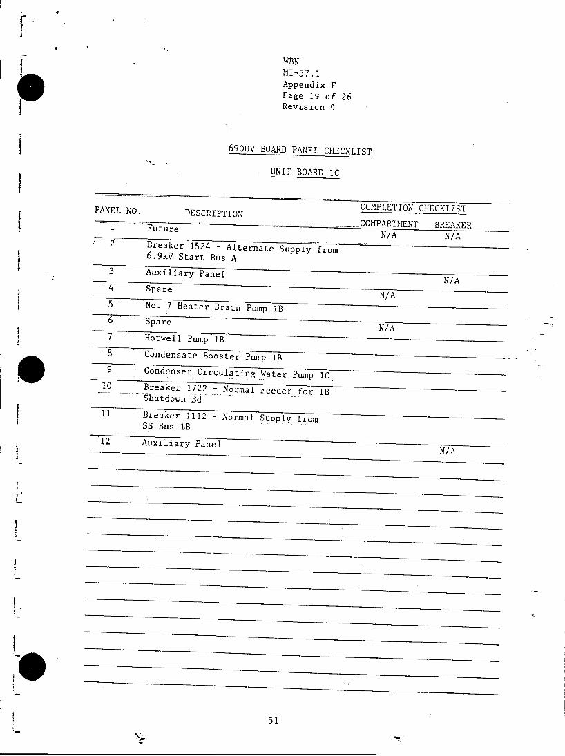
WBNMI-57.1Appendix FPage 19 of 26Revision 9
6900V BOARD PANEL CHECKLIST
UNIT BOARD IC
PANEL NO. DESCRIPTION COCHECKLISTCOMPARTMENT BREAKER.N A
1 Future N/A N/A
2 Breaker 1524 - Alternate Suppiy from6.9kV Start Bus A
3 Auxiliary Panel N/A
4 Spare N/A
5 No. 7 Heater Drain Pump lB6 Spare
N/A7 Hotwell Pump lB
8 Condensate Booster Pump lB9 -Condenser Circulating Water Pump iC
10 Breaker 1722 - Normal Feeder for lBShutdown Bd
11 Breaker 1112 - Normal Supply fromSS Bus 1B
12 Auxiliary Panel N/A
51

4
WBNMI-57.1Appendix FPage 20 of 26Revision 9
6900V BOARD PANEL CHECKLIST
UNIT BOARD ID
COMPLETION CHECKLISTPANEL NO. DESCRIPTIONCOMPARTMENT BREAKER1 Breaker 1124 - Normal Supply from
6.9kV Unit SS Bus 1B2 Auxiliary Panel N/A3 480V Unit Board 1B Xfmr
4 -Hotwell Pump lC
5- -- Condenser Circulating Water Pump ID6- No. 3 Heater Drain Pump IC
7 Standby Main Feed Pump lC
8 Spare
9 Auxiliary Panel N/A
10 Breaker 1624 - Alternate Supply from6.9kV Start Bus B
-11 Spare N/A
52
,It

WBNMI-57.1Appendix FPage 21 of 26Revision .9
6900V BOARD PANEL CHECKLIST
UNIT BOARD 2A
COMPLETION CHECKLISTPANEL NO. DESCRIPTION
COMPARTMN BREAKER1 Future N/A N/A
2 Breaker 1532 - Alternate Suppiy from6.9kV Start Bus A
3 Auxiliary Panel N/A4 Spare N/A
5 480V Unit Board 2A Xfmr
6 No. 3 Heater Drain Pump 2A
7 Hotwell Pump 2A
8 Condensate Booster Pump 2A
9 Condenser Circulating Water Pump 2A
10 Spare
11 Auxiliary Panel N/A
12 Breaker 1212 - Normal Supply from6.9kV Station Service Bus 2A
53
4

WBNMI-57.1Appendix FPage 22 of 26Revision 9
6900V BOARD PANEL CHECKLIST
UNIT BOARD 2B
COMPLETION CHECKLISTPANEL NO. DESCRIPTIONCOMPARTMENT BREAKER1 Auxiliary Panel N/A
2 Breaker 1214 - Normal Supply irom6.9kV Unit SS Bus 2A
3 No. 7 Heater Drain Pump 2A
4 No. 3 Heater Drain Pump 2B
5 Condenser Circulating Water Pump 2B6 Condensate Booster Pump 2B7 Spare N/A8 Breaker 1814 - Normal Feeder for
6.9kV Shutdown Board 2A-A
9 Auxiliary Panel N/A10 Breaker 1632 - Alternate Supply from
6.9kV Start Bus B11 Spare N/A
54

WBNMI-57.lAppendix FPage 23 of 26Revision 9
6900V BOARD PANEL CHECKLIST
UNIT BOARD 2C
COMPLETION CHECKLISTP.ANEL NO. DESCRIPTION
COMPARTHENT BREAKER1 Future N/A N/A
2 Breaker 1534 - Alternate Suppiy from6.9kV Start Bus A
3 Auxiliary Panel N/A
4 Spare N/A
5 No. 7 Heater Drain Pump 2B
6 Spare N/A
7 Hotwell Pump 2B
8 Condensate Booster Pump 2B
9 Condenser Circulating Water Pump 2C
10 Breaker 1822 - Normal Feeder for6.9kV Shutdown Board 2B-B
11 Breaker 1222 - Normal Supply fromUnit SS Bus 2B
12 Auxiliary Panel N/A
55

WBNMI-57. 1Appendix FPage 24 of 26Revision 9
6900V BOARD PANEL CHECKLIST
UNIT BOARD 2D
- ------- ~----COMPLETIONCHKLSPANEL NO. DESCRIPTIONCOMPARTMENT BREAKER-1 Breaker 1224 - Normal Supply from
Unit SS Bus 2B2 Auxiliary Panel
N/A3 480V Unit Board 2B Xfmr4 Hotwell Pump 2C
5 Condenser Circulating Water Pump 2D6 No. 3 Heater Drain Pump 2C
7 Standby Main Feed Pump 2C8 Spare
* 9 Auxiliary Panel N/A
10 Breaker 1634 - Alternate Supply from6.9iV Start Bus B11 Space
N/A
56

WBNMI-57.1Appendix FPage 25 of 26Revision 9
6900V BOARD PANEL CHECKLIST
COMMON SWGR C
COMPLETION CHECKLISTPANEL NO. DESCRIPTION COMPARTHENT BREAKER1 Auxiliary Panel
N/A2 Alt #2 Sup For 6.9 Shutdown Board lB-B & 2B-B3 Alt #1 Sup For 6.9 Shutdown Board 1A & 2A4 Auxiliary Panel
N/A
57

WBNMI-57.1Appendix FPage 26 of 26Revision 9
6900V BOARD PANEL CHECKLIST
COMMON SWGR I)
COMPLETION CHECKLISTPANEL NO. DESCRIPTION COMPARTMENT BREAKER1 Auxiliary Panel
N/A2 ---- Alt #1 -Sup for Shutdown- Board 1B & 2B3 -Alt #2 Sup for Shutdown Board 1A & 2A
-
A
..4 A u i i r P a e -N/. .A
58