s4 dsg 3.0t / s5 3.0t cabriolet / a7 3.0t exhaust...
TRANSCRIPT

S4 DSG 3.0T / S5 3.0T Cabriolet / A7 3.0T Exhaust Installation Guidelines
SE-022-023-024
STāSIS Engineering
2 of 12
S4 DSG S5 A7 3.0T Exhaust Exhaust Kit Installation
Applications
Description
S4 DSG B8 3.0T Exhaust w/Downpipe
S5 B8 3.0T Cabriolet Exhaust w/Downpipe
A7 3.0T Exhaust w/Downpipe
Instructions
1 Before removing any parts, jack the vehicle up, and place the vehicle on four stable jack stands or use a professional vehicle lift.
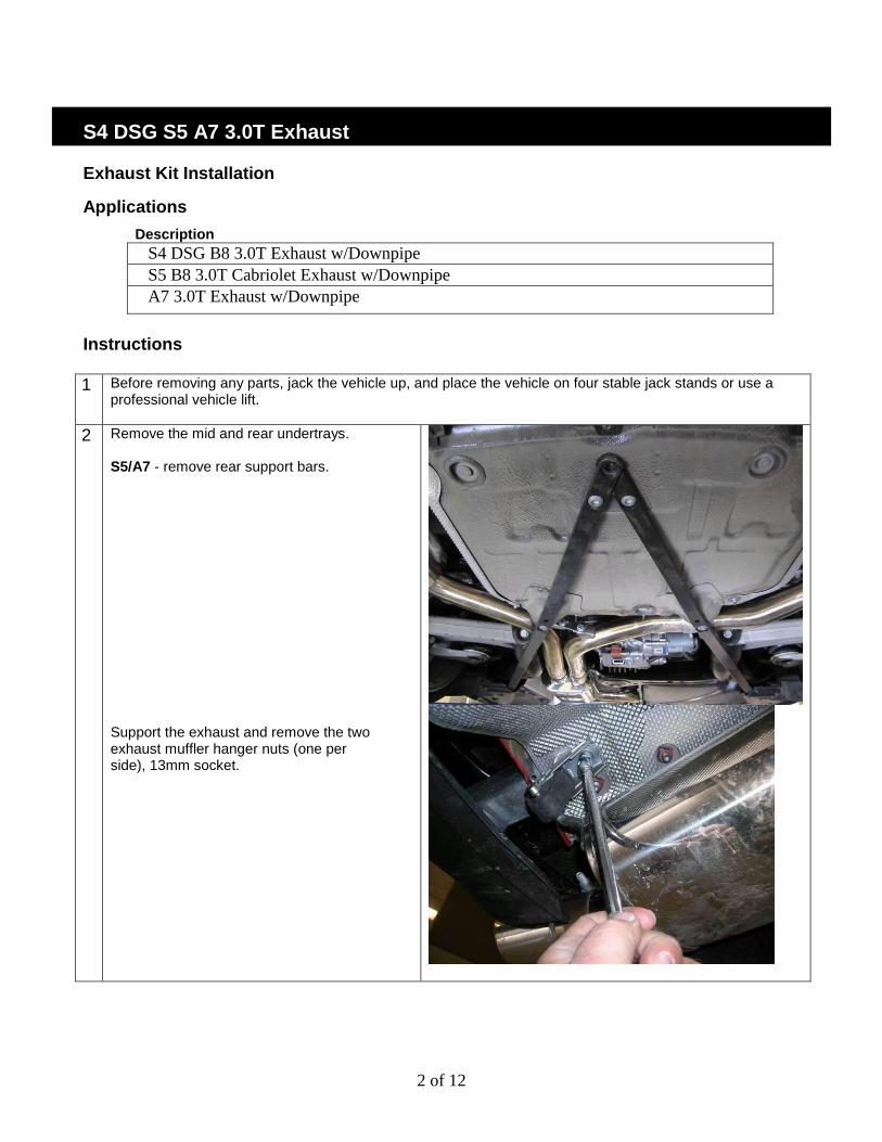
2 Remove the mid and rear undertrays. S5/A7 - remove rear support bars. Support the exhaust and remove the two exhaust muffler hanger nuts (one per side), 13mm socket.

3 of 12
3 Gently pry the two center exhaust rubber hangers of off the exhaust. Use a lubricant (i.e. WD-40) if required.
4 Remove the center chassis cross brace
5 Loosen the 4 13mm exhaust clamp nuts #12. Remove entire rear muffler assembly #3 and #4 in one piece. Remove the front undertrays and downpipe flange nuts #8. Remove downpipes #10 and gaskets #9 from both sides.

4 of 12
6 For proper installation and fitment, please follow the instructions in the correct sequence listed- Hardware supplied: A7: Replacement nuts for factory studs and new gaskets S4/S5: Allen bolts, corresponding nuts, offset crows foot socket, and exhaust gaskets. Install passenger side down-pipe first. Do not torque flange nuts and bolts at this time! Finger tighten only!
7
Slide drivers side down-pipe over passenger side down pipe and install to flange using the hardware and gaskets provided. Note orientation of the clamp before installation, do not tighten the clamp at this time. Do not torque flange nuts and bolts at this time! Finger tighten only!

5 of 12
8 Center downpipes before tightening flange nuts and bolts. Torque – 23 Nm
Warning: Insure that the mid-pipes are
completely centered before tightening flange bolts. If the downpipes are not centered, the exhaust system will have interference issues once all components are installed. The “S” reinforcement bracket on the crossover section should be completely horizontal. If the bracket is at an angle to the ground, twist down pipes until bracket is horizontal before tightening the flange bolts. Support down pipes and tighten the passenger side downpipe clamp. Warning: Insure proper clamp placement!
Align all clamps to the edge of the outer pipe. If the clamp is installed inboard, insufficient clamping force will result in exhaust slippage and alignment issues.

6 of 12
8 Install mid-muffler onto down-pipes and slide exhaust hanger brackets into the rubber hangers with lubricant. Make sure muffler and pipes are centered with adequate space around all components. Slide mid-muffler forward until rubber hangers are canted forward (towards the front of the car) as shown. This allows for exhaust expansion without stretching the hangers. Mid muffler pipe should be approximately ¼” to ½” from the corner of the center tunnel of the vehicle. Clearance will increase due to thermal expansion once exhaust system heats up.

7 of 12
9 Note clamp orientation, do not tighten clamps at this time.
10 Install foam padding in the four locations shown to center the exhaust mid-section. Do not tighten clamps at this time.
Warning: Foam pads must be removed
after the exhaust is completely installed. Failure to remove pads will result in the melting of the pads onto the exhaust system.

8 of 12
10 Install drivers side intermediate pipe with the clamp orientation as shown. Do not tighten clamp at this time Install passenger side intermediate pipe with the clamp orientation as shown. Do not tighten clamp at this time

9 of 12
11 Remove exhaust hanger bracket off of the stock exhaust and slide with lubricant into the drivers side muffler hanger. Note: S4/S5 muffler shown, A7 has single tip outlet Install drivers side muffler into intermediate pipe, do not tighten clamp at this time. Install 13mm nut on exhaust hanger bracket. Slide muffler forward until rubber hanger is canted forward (towards the front of the vehicle) to account for thermal expansion (as shown).
13 Ensure all pipes are centered and clear of any components. Tighten the forward exhaust clamps on the mid muffler.
Warning: Insure proper clamp placement!
Align all clamps to the edge of the outer pipe. If the clamp is installed inboard, insufficient clamping force will result in exhaust slippage and alignment issues.

10 of 12
14 Locate drivers side muffler so that it is centered in the valence cavity and pushed forward so that the STaSIS logo is just visible next to the valence (looking from the top down) Tighten the drivers side intermediate pipe clamp at this time.
Warning: Insure proper clamp placement!
Align all clamps to the edge of the outer pipe. If the clamp is installed inboard, insufficient clamping force will result in exhaust slippage and alignment issues. Tighten the drivers side mid muffler clamp
15 Remove exhaust hanger bracket off of the stock exhaust and install on the passenger side muffler hanger. Install passenger side muffler onto intermediate pipe. Note clamp orientation. Do not tighten clamp at this time. Tighten 13mm nut for the passenger side exhaust hanger bracket

11 of 12
16 Match tip fitment to the driver side muffler. 13mm nuts for the OEM exhaust hanger brackets can be loosened and hanger can be rotated to accommodate side to side movement. Tighten intermediate pipe clamp.
Warning: Insure proper clamp placement!
Align all clamps to the edge of the outer pipe. If the clamp is installed inboard, insufficient clamping force will result in exhaust slippage and alignment issues. Tighten passenger side muffler assembly clamp.

12 of 12
17 Install center support bracket with hardware provided. Mufflers can be spread apart slightly while tightening to accommodate tip alignment. If brackets do not line up, loosen muffler clamps and readjust as necessary. Remove all foam locating pads before running vehicle!
18
S5/A7 - Re-install rear support bars, check for clearance between exhaust system and support bars. Loosen clamps and adjust pipes if additional clearance is needed. Double check tip alignment once all clamps have been retightened. All vehicles – Re-install cross brace and all undertrays. Test drive and check for rattles. Re-adjust as necessary to provide proper clearance.
Exhaust Post Installation Checklist Exhaust
o During and after install, using isopropyl alcohol, wipe off all assembly and shipping
particles from the exhaust. If dust is not wiped off, once the exhaust gets hot, the
particles burn onto the stainless steel finish and become permanent.
o Ensure the exhaust tips on both sides protrude from the bumper evenly and are not
touching any body panels.
o Apply anti seize to all assembly bolts to allow for ease of removal.