sa igesio es o e ag 15 ecueae auomoie gas uie pln t dp tr frdn t t nz tr nt drn n phb lt. th prpd t...
TRANSCRIPT

THE AMERICAN SOCIETY OF MECHANICAL ENGINEERS 88-GT-196345 E. 47 St., New York, N.Y. 10017
€. The Society shall not be responsible for statements or opinions advanced in papers or in dis-
cussion at meetings of the Society or of its Divisions or Sections, or printed in its publications.m Discussion is printed only if the paper is published in an ASME Journal. Papers are available1^[ 0 from ASME for fifteen months after the meeting.
Printed in USA.
Salt Ingestion Test of the AGT 1500 RecuperatedAutomotive Gas Turbine
THOMAS M. BODMANProject Engineer
THOMAS P. PRIOREProgram Manager
Naval Ship Systems Engineering StationPhiladelphia, Pennsylvania
ABSTRACT
A salt ingestion test was performed on the AGT 1500recuperated automotive gas turbine engine at the Naval ShipSystems Engineering Station (NAVSSES) for the U.S. MarineCorps. The Marine Corps was concerned about the AGT 1500'sability to tolerate their amphibious and maritime environments.The AGT 1500 was operated for two 450 hour endurance runsburning Navy diesel fuel' and ingesting aerosol salt. It suffered nofailures or significant loss of power as a result of the ingested salt oroperations with Navy diesel fuel.
INTRODUCTION
In 1984, the U.S. Marine Corps was evaluating the U.S.Army's MIAI Abrams Main Battle Tank as a replacement fortheir M60 Tanks. They were investigating several areas of concernto them. One major area was the AGT 1500 gas turbine enginemanufactured by TEXTRON Lycoming. The Marine Corps hadexperienced some problems with gas turbines in Army designedhelicopters not performing well in an amphibious environment. Asa result of this experience the Marine Corps Development andEducation Command (MCDEC) asked the Gas Turbine Branch ofthe NAVSSES to evaluate and test the AGT 1500 gas turbineengine.
The engine's performance was predicted based on MarineCorps unique factors developed during the evaluation. Theevaluation predicted that the performance of the AGT 1500 gasturbine engine would be successful in service with the MarineCorps.
The objectives of the test were to be limited in scope. Theperformance of one production engine was tested against themarine unique factors only. The Army had done extensive testingand there was no need to duplicate their tests.
The Marine unique factors for evaluation were: an aerosol saltspray in the engine air inlet to simulate amphibious assaultoperations, use of US Navy diesel fuel as would be supplied duringdeployment and an operating profile based on Marine Corpsexperience.
' MIL-F-16884H Fuel Oil, Diesel, Marine; NATO F76
For this test, failures are defined as any occurrence whichresulted in an engine start abort, required unscheduled maintenanceor caused engine performance to fall below 60% of the baselineengine performance. The value of 60% was chosen by the MarineCorps because it is equivalent to the power available in the M60tank. Failures are classified into two categories, pertinent andnon-pertinent failures. Pertinent failures are failures that aredirectly caused by or resulting from the simulated Marine Corpsunique environment. Non-pertinent failures are failures that arenot directly caused by or resulting from the Marine Corps uniqueenvironment.
THE AGT 1500 GAS TURBINE ENGINE
Engine DescriptionThe AGT 1500 gas turbine engine, Figure I, has a dual spool
gas producer. The Low Pressure (LP) compressor is a five stageaxial flow design driven by a single stage LP turbine. The HighPressure (HP) compressor has five stages, four axial flow stageswith one radial flow exit stage, driven by a single stage HP turbine.The LP and UP compressors are counter-rotating. The engine hasa cross-counterflow plate type recuperator and a single combustorcan with a scroll. The output power is derived from a two stage freepower turbine connected to a single stage planetary reduction gear.Starting and accessory drive is provided for by the accessory gearbox connected to the HP compressor rotor.
The gas flow configuration, Figure 2, brings ambient air intothe LP compressor through variable inlet guide vanes. The LPcompressor discharge is directed to the H P compressor through anintermediate casing. The HP compressor discharges through aradial fifth stage to the diffuser housing which directs the air to therecuperator. Here, exhaust gases heat the compressed air whichreduces the fuel flow requirements of the engine. The recuperatordischarges the heated compressed air to the combustor can andscroll. The hot gases produced in the combustor can are directedthrough the scroll to the LP and HP compressor turbines. The hotgases then enter the two stage power turbine through variableturbine stators. The exhaust gases flow from the center of therecuperator outward to heat the compressor discharge air and outto atmosphere.
Presented at the Gas Turbine and Aeroengine CongressAmsterdam, The Netherlands—June 6-9, 1988
Copyright © 1988 by ASME
Downloaded From: https://proceedings.asmedigitalcollection.asme.org/pdfaccess.ashx?url=/data/conferences/asmep/83605/ on 05/06/2018 Terms of Use: http://www.asme.org/about-asme/terms-of-use

`. L
'. 'c _ .,.^_ _ _.,tea ......,.€ `W'/d ., " e . . ^.^. o ._ _ - - — }• !I1;i+'7 .
FIG. I AGT 1500 GAS TURBINE ENGINE
II
Engine Material EvaluationThe AGT 1500 gas turbine engine materials were evaluated to
predict the risk of corrosive failures in an amphibious environment.The areas of concern were the LP compressor casing, the HPturbine, the LP turbine and the power turbine. The LP compressorhousing is a cast ductile iron. In a salt water atmosphere thepotential for galvanic corrosion between the cast iron and the otherstainless steel components was considered high. Inconel 713 C and713 LC is used in many components in the turbine sections.Experience with these materials, in Naval service, is prematurefailures due to hot corrosion. These areas were not considered highrisk due to the limited exposure to salt, the high power profileswhen exposed to salt, and the relatively frequent maintenancecycles in the automotive application compared to Naval service.
The remaining components were evaluated as little or no risk.For example, the recuperator frame is cast 17-4PH steel and theheat exchanger plates are Inconel 625. These materials are highlyresistant to corrosive attack. The combustor materials, HastalloyX and the Zirconial'NiCrAIY thermal barrier coating, are thesame materials as used on the LM 2500 marine gas turbinepropulsion engine and have exhibited long life in Naval service.
TEST SITE INSTALLATION
The AGT 1500 gas turbine engine was installed in a test cell atNAVSSES for this salt ingestion test. The test site was designed tosubject the engine to the same operating conditions as the M IA1Tank. Therefore wherever practical, the engine's support systemsfrom the tank were utilized, as described below. Figure 3 shows thetest cell with the engine and all the support systems completelyinstalled.
Engine Mounting & Loading SystemThe tank's transmission was not used. Instead, the engine was
directly connected to a perforated disc waterbrake which providedtorque load to the engine. The waterbrake was controlled byremotely operated V-notched ball valves in both the supply anddrain water lines. The waterbrake was cantilevered off the rear ofthe engine. Both the engine and waterbrake were supported by afoundation which was designed to simulate the tank's enginemounting. The engine's thermal growth was allowed for by meansof a sliding foot which was similar to the tank's mounting.
Engine Intake & Exhaust SystemIn order to provide duct losses during the test as close as
possible to the actual conditions, the tank's inlet air box andexhaust ducting were used. The inlet air box consisted of an inertialspin tube prefilter and three V-Pack barrier filters. The prefilterrequires a scavenge exhaust blower which was simulated with afacility electric blower. The installation in the tank uses a blowerdriven by the tank's transmission. In addition, the Marine Corpsplans to use a deep water fording kit to minimize water intakeduring an amphibious assault. The proposed kit will reduce theengine inlet area. To simulate this duct loss, a perforated damperwas installed in the facility intake duct. The design was based onthe geometry of the prototype deep water lording kit and providedthe same engine intake area. The tank's exhaust duct wasconnected to the engine via a riser so that the duct would clear thewaterbrake.
Facility DuctingThe facility intake and exhaust ducting was designed to
connect the tank's intake and exhaust to atmosphere. This facility
2
Downloaded From: https://proceedings.asmedigitalcollection.asme.org/pdfaccess.ashx?url=/data/conferences/asmep/83605/ on 05/06/2018 Terms of Use: http://www.asme.org/about-asme/terms-of-use
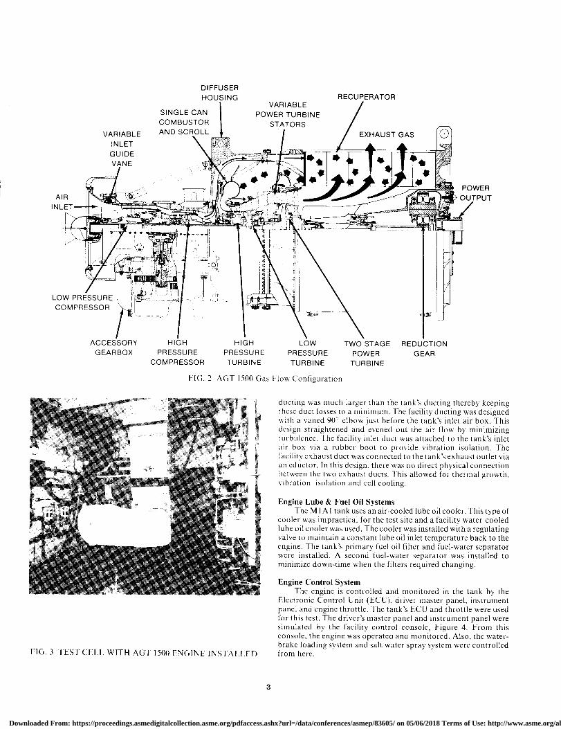
DIFFUSERHOUSING RECUPERATOR
VARIABLESINGLE CAN POWER TURBINECOMBUSTOR STATORS
VARIABLE AND SCROLL EXHAUST GASINLET
GUIDE ^.._^
POWER
TINLE _.^,. OUTPUTAIR ^
ti I.. A/
_ K I
LOW PRESSURE i
COMPRESSOR
ACCESSORY HIGH HIGH LOW TWO STAGE REDUCTIONGEARBOX PRESSURE PRESSURE PRESSURE POWER GEARCOMPRESSOR TURBINE TURBINE TURBINE
FIG. 2 AGT 1500 Gas Flow Configuration
ducting was much larger than the tank's ducting thereby keepingthese duct losses to a minimum. The facility ducting was designedwith a vaned 90° elbow just before the tank's inlet air box. Thisdesign straightened and evened out the air flow by minimizingturbulence. The facility inlet duct was attached to the tank's inletair box via a rubber boot to provide vibration isolation. Thefacility exhaust duct was connected to the tank's exhaust outlet viaan eductor. In this design, there was no direct physical connectionbetween the two exhaust ducts. This allowed for thermal growth,vibration isolation and cell cooling.
Engine Lube & Fuel Oil SystemsThe M I A 1 tank uses an air-cooled lube oil cooler. This type of
cooler was impractical for the test site and a facility water-cooledlube oil cooler was used. The cooler was installed with a regulatingvalve to maintain a constant lube oil inlet temperature back to theengine. The tank's primary fuel oil filter and fuel-water separatorwere installed. A second fuel waterseparator was installed to
r minimize down-time when the filters required changing.
Engine Control SystemThe engine is controlled and monitored in the tank by the
Electronic Control Unit (ECU), driver master panel, instrumentpanel and engine throttle. The tank's ECU and throttle were usedfor this test. The driver's master panel and instrument panel weresimulated by the facility control console, Figure 4. From thisconsole, the engine was operated and monitored. Also, the water-brake loading system and salt water spray system were controlled
FIG. 3 TEST CELL WITH AGT 1500 ENGINE INSTALLED from here.
3
Downloaded From: https://proceedings.asmedigitalcollection.asme.org/pdfaccess.ashx?url=/data/conferences/asmep/83605/ on 05/06/2018 Terms of Use: http://www.asme.org/about-asme/terms-of-use

FIG. 4 FACILITY ENGINE CONTROL CONSOLE
Salt Water Spray SystemIn order to simulate the salt aerosol environment required by
this test, salt water was sprayed into the facility intake duct. Twospray nozzle locations were required for the large range of saltconcentrations called for in the test plan. The I ppm and less rangewas handled by a single nozzle located immediately after the vanedelbow. The concentrations greater than I ppm were created by apair of nozzles located up stream of the vaned elbow. This providedmore time for the heavy salt water flows coming from these nozzlesto thoroughly mix with the engine's intake air. The nozzles weresupplied with salt water on one side and compressed air foratomization on the other side. The salt concentration in the intakeduct was varied by adjusting the salt water flow rate and thecompressed air pressure to the nozzles.
Engine Electrical PowerElectrical power for the ECU was provided by a facility 28 volt
DC power supply. Engine starting current was provided by sixbatteries identical to those used in the M IA! Tank. The batterieswere charged by a facility battery charger instead of the tank'salternator which is driven by the tank's transmission.
TEST OPERATIONS
The engine was operated through two 450 hour test runs. Eachtest run simulated the projected U.S. Marine Corps operatingprofile for the MIA! Main Battle Tank and lasted one MarineCorps vehicle maintenance cycle. Every practical effort was madeto accurately simulate the actual conditions that the tank installedengine would experience. The ambient conditions of pressure,temperature and humidity were not controlled.
The engine ran for the entire test on Navy diesel fuel. This isthe fuel the Marine Corps plans to use in the MIAI tank whendeployed with the Navy. The engine ran for the entire test with thisfuel since there is no extended operating experience with Navydiesel fuel.
During the test, preventive maintenance was performed inaccordance with the Army's Preventive Maintenance Checks andService (PMCS) system. The maintenance was performed every150 hours of operation which is the equivalent of six months oftank operation. During the checks the primary fuel filter andfuel-water separator filter elements were replaced. The fuel nozzle
was replaced with a new or clean nozzle. In addition, the enginecasing and the attached components were inspected for overallcondition.
At the conclusion of the first 450 hour test run, in addition tothe PMCS performed, the compressor rotors and stators weremanually cleaned with a waterwash solution. The lube oil and lubeoil filter, as well as the V-Pack filter elements in the tank's inlet airbox were changed at this time.
The engine was operated for a calibration run at the beginningand end of the test to map the engine's performance. Thecalibration run consisted of operating the engine for one hour ateach power level once steady state conditions were reached. Eachcalibration run began at idle and progressed sequentially throughthe power levels at intervals of 25%.
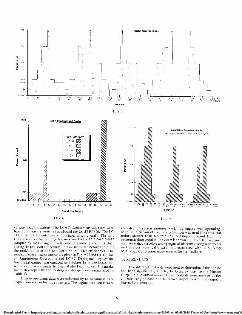
Three different operating profiles were developed to simulatethe Marine Corps unique operating profile; the AmphibiousOperations cycle, the Landing Craft Air Cushion (LCAC) Deploy-ment cycle and the Normal Operations cycle. During each 450 hourtest run there were three Amphibious Operations cycles, threeLCAC Deployment cycles and 48 Normal Operations cycles. Thesequence of the cycles for each test run is given in the 450 hour testrun profile, Table I. The engine was allowed to cool down for onehour after each Amphibious Operations cycle and each NormalOperations cycle. Immediately after each LCAC DeploymentCycle, a Normal Operations cycle was run.
The Amphibious Operations cycle simulates the tank andengine on conventional landing craft during an amphibiousassault. The LCAC Deployment cycle simulates engine operationwhile the tank is deployed on a hovercraft type vehicle which willproduce a salt aerosol mist when going through the surf. Theremainder of the engine's operating profile is simulated by theNormal Operating cycle. The operating profiles for all of the cycleswere derived from information provided to NAVSSES by theMarine Corps. This information is based on their actual experiencewith the M60 tank. The cycle profiles are shown as Figures 5,6 and7.
The Marine Corps projected that 3-4% of the engine's lifecycle would be in a salt aerosol environment and that deploymenton the LCAC would be 0.6-0.8% of the life cycle. To simulate this,salt water was sprayed into the intake ducting during the Amphib-ious Operation cycle and the LCAC Deployment cycle. TheAmphibious Operations cycles were 3% of the test and the LCACDeployment cycles were 0.8% of the test. The total engine saltexposure was 3.8% of the test. The salt ingestion rates weredetermined from studies performed at NAVSSES. The Amphib-ious Operations salt rate was derived from a world-wide survey of
Table
450 HOUR TEST RUN PROFILE
Cycle Number Cycle
1-9 Normal Operations10 Amphibious Operations11-15 Normal Operations16 LCAC Deployment17-21 Normal Operations22 Amphibious Operations23-27 Normal Operations28 LCAC Deployment29-35 Normal Operations36 Amphibious Operations37-41 Normal Operations42 LCAC Deployment43-54 Normal Operations
Downloaded From: https://proceedings.asmedigitalcollection.asme.org/pdfaccess.ashx?url=/data/conferences/asmep/83605/ on 05/06/2018 Terms of Use: http://www.asme.org/about-asme/terms-of-use
100%
75%
'm
50%
am
25%
T. Idle
I dle
51rutOrwn
33 3 [l3
143 2/0 300 330 360 390 420 450 480 510 540 (m1n)0.5 1.0 1.5 2.0 2.5 3.0 3.5 40 45 5.0 5.5 6.0 6.5 7.0 75 8.0 8.5 9 0 (hours)
Duration
FIG. 5
100$ LCRC Deployment Cycle
Salt Rate (ppm)
500
50
1.0
60.1
50^
a
Idle /
Shutdown I I I IJ I 0 5 10 15 20 2530 35 40 45 50 55 60 65 70 75 80
Duration (min)
FIG. 6
various beach locations. The LCAC Deployment salt rates werebased on measurements taken aboard the LC JEFF (B). The LCJEFF (B) is a prototype air cushion landing craft. The saltingestion rates for both cycles were verified with a particulate
sampler by measuring the salt concentrations in the inlet ductduring the test. Salt concentration was measured before and afterthe tank's air inlet box to determine the filter efficiencies. Theresults of these measurements are given in Tables II and III. Duringall Amphibious Operations and LCAC Deployment cycles thefording kit damper was engaged to simulate the intake losses thatwould occur while using the Deep Water Fording Kit. The intakelosses developed by the fording kit damper are summarized inTable IV.
Engine operating data were collected by an automatic dataacquisition system for the entire test. The engine parameters were
l00%
75e
Soy
0.a
25%
Idle
^^^^\^\^^^\\\\\n^^1\^ ara\tea\^;^^e♦\\\\a\\\\\\\\`
FIG. 7
recorded every ten minutes while the engine was operating.Manual initiation of the data collection was used for those testpoints shorter than ten minutes. A sample printout from theautomatic data acquisition system is shown in Figure 8 . To insureaccuracy in the data before testing began, all of the measuring instrumentsand devices were calibrated in accordance with U.S. NavyMetrology Calibration requirements for test facilities.
TEST RESULTS
Two different methods were used to determine if the enginehad been significantly affected by being exposed to the MarineCorps unique environment. These methods were analysis of thecollected engine data and teardown inspections of the engine'sinternal components.
N7
Downloaded From: https://proceedings.asmedigitalcollection.asme.org/pdfaccess.ashx?url=/data/conferences/asmep/83605/ on 05/06/2018 Terms of Use: http://www.asme.org/about-asme/terms-of-use

Table II
SUMMARY OF AMPHIBIOUS OPERATIONSCYCLE SALT RUNS
Power Salt Filter
Level Concentration(ppm) Efficiency(/.)
Idle 1.0 82
257. 1.0 81
50% 1.0 74
75. 1.0 74
1007. 1.0 78
Table III
SUMMARY OF LCAC DEPLOYMENT CYCLE SALT RUNS
Power Salt Filter
Level Concentration(ppm) Efficiency(%)
Idle 0.1 60
507. 0.1 67
Idle 500 99
Idle 50 98
1007 1.0 78
Table IV
FORDING KIT DAMPER PRESSURE LOSSES
Power Level Pressure Losses( HO)
Idle 1.0
257 1.5
507 2.25
75• 3.7
1007 5.0
Engine Teardown InspectionsThere were three teardown inspections of the engine during
the test. An initial inspection to establish the baseline and aninspection at the conclusion of each 450 hour test run. As a part ofeach teardown inspection, the tank's inlet air box was inspected.
Inspection of the tank's inlet air box at the end of each test runrevealed an accumulation of salt on the dirty air side of the filters,as could be expected. In addition, minor salt deposits wereobserved on the clean air side of the filter air box. These depositswere attributed to small salt particles which passed through theinlet air filters. These deposits were found not only in the clean airside but also on the engine's bellmouth in a heavier concentration.The heaviest concentration of salt was found on those elements ofthe inlet air box that are closest to the engine as it is installed in thetank. This is a result of the geometry of the air box. Salt tends tobuild up in this region because the air velocities are slower here andthe box is sloped toward this area.
The teardown inspections were performed by partially disas-sembling the engine. The top covers from the LP and HPcompressors were removed to inspect the blades and stators in thisregion. During the final inspection, salt deposits were found in thefirst three stages of the LP compressor rotor. However, nodeterioration or corrosion of the blades was observed underneaththese deposits.
The gas producer was separated from the power turbine! recperator and the power turbine removed from the recuperator to
AGT1500-TEST FACILITY
DATE-10/29/86
TIME-05:20:00
0 INLET RAM PRESSURE -6.3 "H=O
1 INLET STATIC PRESSURE -7.7 "HBO
2 HIGH COMPRESSOR DISCHARGE
PRESSURE 32.7 PSIG
3 TURBINE OIL PRESSURE 60.8 PSIG
4 FUEL SUPPLY PRESSURE 18.4 PSIG
5 WATER BRAKE INLET
PRESSURE 46.8 PSIG
7 WATER BRAKE OUTLET
PRESSURE 4.9 PSIG
6 DIFFERENTIAL PRESSURE
ACROSS FUEL FILTER 0.8 PSID
8 FUEL SUPPLY FLOW 1.119 GPM
9 HIGH COMPRESSOR RPM 39802 RPM
10 POWER TURBINE RPM 2894 RPM
11 POWER TURBINE INLET TEMP. 1375 DEG. F
12 HORSEPOWER 982.4 HP
13 TORQUE 1790.4 FT-LBS
THERMOCOUPLE TEMPERATURE READINGS
15 TC-1 INLET DUCT 53 DEG. F
16 TC-2 HIGH COMPRESSOR
DISCHARGE 277 DEG. F
17 TC-3 RECUPERATOR OUTLET 777 DEG. F
18 TC-4 FUEL SUPPLY INLET 69 DEG. F
19 TC-5 TURBINE OIL INLET 272 DEG. F
20 TC-6 TURBINE OIL OUTLET 184 DEG. F
21 TC-7 TEST CELL 73 DEG. F
22 TC-8 WATER BRAKE INLET 61 DEG. F
23 TC-9 WATER BRAKE OUTLET 117 DEG. F
24 TC-10 WATER BRAKE FRONT
BEARING 62 DEG. F
25 TC-11 WATER BRAKE REAR
BEARING 63 DEG. F
FIG. 8 AUTOMATIC DATA ACQUISITON SYSTEMSAMPLE PRINTOUT
allow inspection of the hot section of the engine. Most of the partsof the hot section could be observed with the unaided eye.However, inspection of the combustor scroll and parts of thepower turbine was performed with a flexible borescope. Through-out all of the inspections no visible evidence of deteriorationcaused by the ingested salt was observed in the hot or cold sectionsof the engine. Some minor mechanical wear was observed in theturbine sections such as minor surface cracking and slight erosionof the LP turbine nozzle block.
Metallurgical inspections by NAVSSES metallurgists werealso conducted, as part of each teardown inspection. During theseinspections particular attention was paid to the areas of concern,the LP compressor casing and the turbine sections. No evidence ofmetallurgical damage due to ingested salt corrosion or hotcorrosion as a result of operations with Navy diesel fuel was found.
Engine Data AnalysisThe collected engine data were corrected to a standard day of
59°F and 29.92"Hg absolute in accordance with MIL-E- 17341 C 2 .
2 MIL-E-17341C (Ships) Engines, Gas Turbine, Propulsion andAuxiliary Naval Shipboard.
Downloaded From: https://proceedings.asmedigitalcollection.asme.org/pdfaccess.ashx?url=/data/conferences/asmep/83605/ on 05/06/2018 Terms of Use: http://www.asme.org/about-asme/terms-of-use

AST 1500 SALT TEST-RUN #1PERCENT POWER vs. CYCLE #
PERCENT OF BASELINE FULL POWER
100
90
80
70
60
50 0 5 10 15 20 25 30 35 40 45 50 55
CYCLE NUMBER
+ +
L1IltilpI I TI __
FIG. 9
100
90
80
70
00
Graphs of horsepower, Figures 9 and 10, for each test run weredeveloped from the corrected data, the graphs plot full horsepowerversus cycle number and show similar results.
One hundred percent on the graphs represents the maximumhorsepower developed during the initial performance data run.The graphs show the horsepower declining during both test runs.This decline is not unusual for a gas turbine engine that has run forover 900 hours of performance testing. The degradation experi-enced during the first test run resulted from the compressor beingdirty. This is evident because the horsepower returned to itsoriginal level after the compressor was cleaned. The degradationduring the second test run is more severe than what was observedduring the first test run. This degradation is not only a result of adirty compressor as during the first test run but also indicates thatthe engine's internal components are beginning to degrade mechani-cally as described in the Engine Teardown Inspection Section.Data collected during the calibration runs showed the maximumpower available degrade from 100% to 97.5 %.
AST 1500 SALT TEST-RUN #2PERCENT POWER vs. CYCLE #
PERCENT OF BASELINE FULL POWER
TT±T H '+
i li
500 5 10 15 20 25 30 35 40 45 50 55
CYCLE NUMBER
FIG. 10
SUMMARY
NAVSSES logged a total of 942 hours and 20 minutes ofoperation on the AGT 1500 gas turbine engine. During the test,engine performance never fell below 90% of the baseline perfor-mance. There were no engine start aborts or any unscheduledmaintenance performed as a result of the Marine Corps uniqueenvironment or burning Navy diesel fuel in the engine.
The AGT 1500 gas turbine engine was tested under simulatedMarine Corps life cycle conditions for over 900 hours. The engineperformance degraded 2.5 percent for the entire test. No pertinentfailures occurred. The final teardown inspection revealed that theengine was in good condition and capable of continued operation.The AGT 1500 performed satisfactorily and was recommended foruse in Marine Corps service.
ACKNOWLEDGEMENTS
We express our thanks to TEXTRON Lycoming for providingFigures I and 2. We appreciate the efforts of Joel Huston inproviding figures 5, 6 and 7. We also appreciate the efforts of all theengineers and mechanics at the Naval Ship Systems EngineeringStation who made this test possible.
7
Downloaded From: https://proceedings.asmedigitalcollection.asme.org/pdfaccess.ashx?url=/data/conferences/asmep/83605/ on 05/06/2018 Terms of Use: http://www.asme.org/about-asme/terms-of-use