safety & installation instructions - air quality solutions · safety & installation...
TRANSCRIPT
Safety & Installation InstructionsModel 6504
Intelligent Zoned Comfort Control System

2 © Research Products Corp.
TABLE OF CONTENTS
WARNINGS AND CAUTIONS . . . . . . . . . . . . . . . . . . . . . . .3
CONTROL PANEL SPECIFICATIONS . . . . . . . . . . . . . . . . .3
CONTROL PANEL LAYOUT . . . . . . . . . . . . . . . . . . . . . . . . .4
RUN WIRE FOR THE SYSTEM . . . . . . . . . . . . . . . . . . . . . .5
MOUNT THE CONTROL PANEL . . . . . . . . . . . . . . . . . . . . .6
SET THE CONTROL CONFIGURATION SWITCHES/JUMPER . . . . . . . . . . . . . . . . . . . . . . . . . . . . . .7
WIRE THE SYSTEM . . . . . . . . . . . . . . . . . . . . . . . . . . . . . . .8
Select and Wire the Transformers to the Control Panel . . . .8
Install the Model 8570 Thermostats and Wire to the Control Panel . . . . . . . . . . . . . . . . . . . . . . . . . . . . . . . . . . . .9
Wire the HVAC Equipment to the Control Panel . . . . . . . .10
Wire the Zone Dampers to the Control Panel . . . . . . . . . .12
Wire a Plenum Sensor to the Control Panel – OPTIONAL . . . . . . . . . . . . . . . . . . . . . . . .12
Wire an Outdoor Sensor to the Control Panel – OPTIONAL . . . . . . . . . . . . . . . . . . . . . . . .13
Wire an Aprilaire Automatic Humidifier Control (AHC) to the Control Panel – OPTIONAL . . . . . . . . . . . . . . . . . . .14
Wire an EAC, ERV or Ventilation Damper to the Control Panel – OPTIONAL . . . . . . . . . . . . . . . . . . . . . . . .15
START UP AND TEST . . . . . . . . . . . . . . . . . . . . . . . . . . . .17
SEQUENCE OF OPERATION . . . . . . . . . . . . . . . . . . . . . . .22
Automatic Changeover . . . . . . . . . . . . . . . . . . . . . . . . . . .22
Initial Power Up or Reset . . . . . . . . . . . . . . . . . . . . . . . . . .22
Damper Outputs . . . . . . . . . . . . . . . . . . . . . . . . . . . . . . . .22
Heating Equipment Outputs – Configured for HEAT/COOL Operation . . . . . . . . . . . . . . . . . . . . . . . . . . . .23
Heating Equipment Outputs – Configured for HEAT PUMP Operation . . . . . . . . . . . . . . . . . . . . . . . . . . .24
Emergency Heat Equipment Outputs – Applies Only When Configured for HEAT PUMP Operation . . . . . . . . . . .25
Cooling Equipment Outputs . . . . . . . . . . . . . . . . . . . . . . . .25
EAC Output . . . . . . . . . . . . . . . . . . . . . . . . . . . . . . . . . . . .26
ERV/Vent Output . . . . . . . . . . . . . . . . . . . . . . . . . . . . . . . .26
AHC Operation . . . . . . . . . . . . . . . . . . . . . . . . . . . . . . . . .27
CONTROLS:
• Up to four zones
• Separate two-stage heating and two-stage coolingequipment
• Two stage heat pumps with one stage of auxiliary heat
• Energy Recovery Ventilators or Model 6506 VentilationDamper
• Electronic Air Cleaners
• 2-wire or 3-wire dampers
REQUIRES:
• Two 24-volt transformers: one for control panel andthermostats, and one for dampers
• One Aprilaire Model 8570 Thermostat per zone
• Standard thermostat wire
OPTIONAL:
• Plenum Temperature Sensor (Aprilaire Model 8052)
• Model 56 Aprilaire Automatic Humidifier Control
• Outdoor Temperature Sensor (Aprilaire Model 8052 – notneeded if installed with an AHC)INTEGRATES WITH:
• Aprilaire Automatic Humidifier Control (AHC) to enhancehumidity control
• Aprilaire Model 8570 Thermostat
3
WARNINGS AND CAUTIONS
WARNING
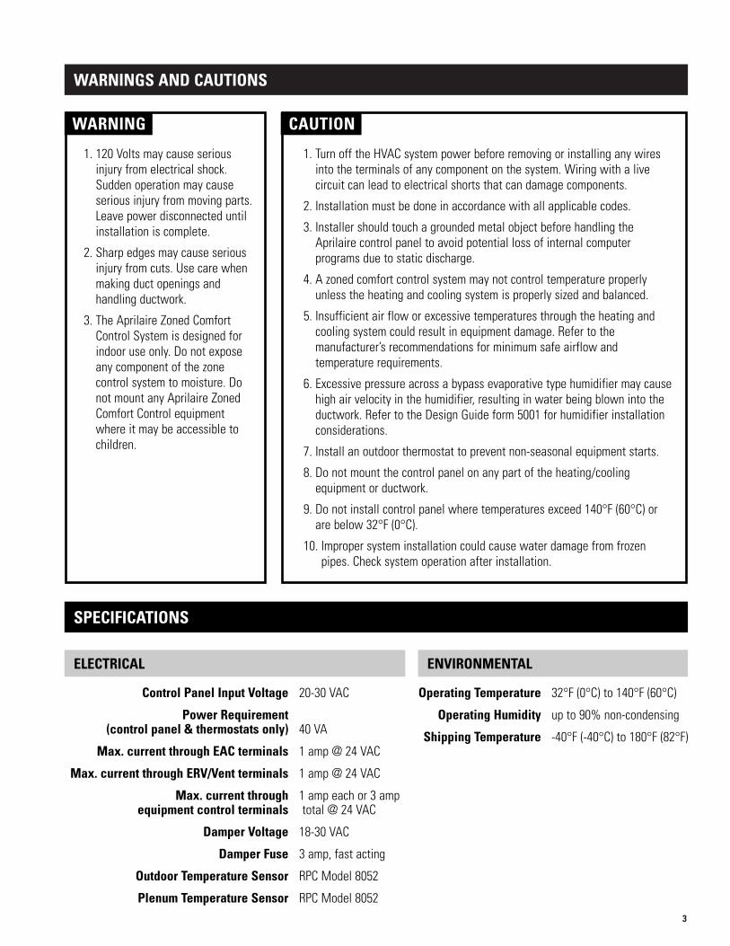
1. 120 Volts may cause seriousinjury from electrical shock.Sudden operation may causeserious injury from moving parts.Leave power disconnected untilinstallation is complete.
2. Sharp edges may cause seriousinjury from cuts. Use care whenmaking duct openings andhandling ductwork.
3. The Aprilaire Zoned ComfortControl System is designed forindoor use only. Do not exposeany component of the zonecontrol system to moisture. Donot mount any Aprilaire ZonedComfort Control equipmentwhere it may be accessible tochildren.
CAUTION
1. Turn off the HVAC system power before removing or installing any wiresinto the terminals of any component on the system. Wiring with a livecircuit can lead to electrical shorts that can damage components.
2. Installation must be done in accordance with all applicable codes.
3. Installer should touch a grounded metal object before handling theAprilaire control panel to avoid potential loss of internal computerprograms due to static discharge.
4. A zoned comfort control system may not control temperature properlyunless the heating and cooling system is properly sized and balanced.
5. Insufficient air flow or excessive temperatures through the heating andcooling system could result in equipment damage. Refer to themanufacturer’s recommendations for minimum safe airflow andtemperature requirements.
6. Excessive pressure across a bypass evaporative type humidifier may causehigh air velocity in the humidifier, resulting in water being blown into theductwork. Refer to the Design Guide form 5001 for humidifier installationconsiderations.
7. Install an outdoor thermostat to prevent non-seasonal equipment starts.
8. Do not mount the control panel on any part of the heating/coolingequipment or ductwork.
9. Do not install control panel where temperatures exceed 140°F (60°C) orare below 32°F (0°C).
10. Improper system installation could cause water damage from frozenpipes. Check system operation after installation.
SPECIFICATIONS
ELECTRICAL ENVIRONMENTAL
Operating Temperature 32°F (0°C) to 140°F (60°C)
Operating Humidity up to 90% non-condensing
Shipping Temperature -40°F (-40°C) to 180°F (82°F)
Control Panel Input Voltage 20-30 VAC
Power Requirement (control panel & thermostats only) 40 VA
Max. current through EAC terminals 1 amp @ 24 VAC
Max. current through ERV/Vent terminals 1 amp @ 24 VAC
Max. current through 1 amp each or 3 ampequipment control terminals total @ 24 VAC
Damper Voltage 18-30 VAC
Damper Fuse 3 amp, fast acting
Outdoor Temperature Sensor RPC Model 8052
Plenum Temperature Sensor RPC Model 8052
4
CONTROL PANEL LAYOUT (See Figure 1)
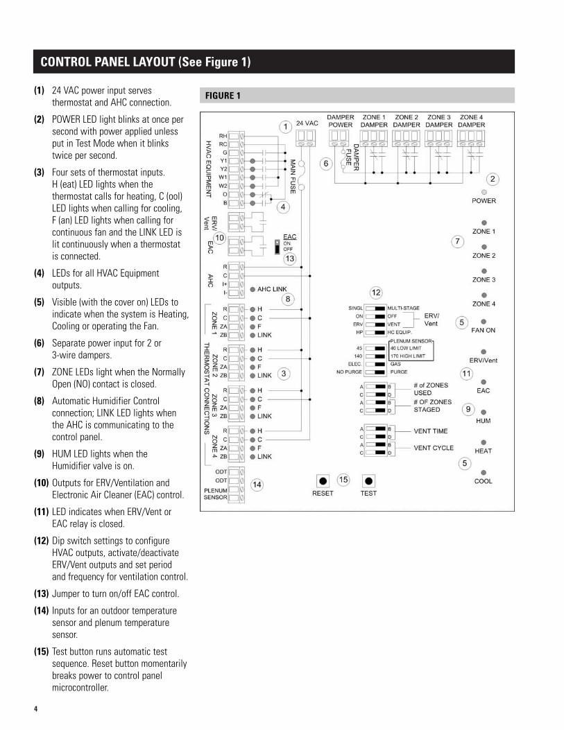
(1) 24 VAC power input servesthermostat and AHC connection.
(2) POWER LED light blinks at once persecond with power applied unlessput in Test Mode when it blinkstwice per second.
(3) Four sets of thermostat inputs. H (eat) LED lights when thethermostat calls for heating, C (ool)LED lights when calling for cooling, F (an) LED lights when calling forcontinuous fan and the LINK LED islit continuously when a thermostat is connected.
(4) LEDs for all HVAC Equipmentoutputs.
(5) Visible (with the cover on) LEDs toindicate when the system is Heating,Cooling or operating the Fan.
(6) Separate power input for 2 or 3-wire dampers.
(7) ZONE LEDs light when the NormallyOpen (NO) contact is closed.
(8) Automatic Humidifier Controlconnection; LINK LED lights whenthe AHC is communicating to thecontrol panel.
(9) HUM LED lights when the Humidifier valve is on.
(10) Outputs for ERV/Ventilation andElectronic Air Cleaner (EAC) control.
(11) LED indicates when ERV/Vent orEAC relay is closed.
(12) Dip switch settings to configureHVAC outputs, activate/deactivateERV/Vent outputs and set period and frequency for ventilation control.
(13) Jumper to turn on/off EAC control.
(14) Inputs for an outdoor temperaturesensor and plenum temperaturesensor.
(15) Test button runs automatic testsequence. Reset button momentarilybreaks power to control panelmicrocontroller.
FIGURE 1

5
RUN WIRE FOR THE SYSTEM (See Figure 2)
FIGURE 2
Single-Stage Two-Stage Boiler w/AC Radiant 1st Stage Heat, Single-Stage Two-StageSystem TypeFurnace & A/C Furnace & A/C (2-xformer) Furnace 2nd Stage Heat & A/C Heat Pump Heat Pump
Wires 4 6 5 5 5 7
TABLE 1 – WIRES REQUIRED FOR VARIOUS HVAC EQUIPMENT TYPES
WIRE TYPE: Standard 18-24 gauge stranded or solid thermostat wire can be used for all wire runs.
IMPORTANTAvoid running thermostat, AHC and sensor wires along side line voltage wires to prevent electrical noise on the IntelligentZoned Comfort Control system.
Model 8570 Thermostat
Model 6504 Control Panel
Zone Dampers
Plenum or OutdoorTemperature Sensor
AutomaticHumidifier Control
Energy Recovery Ventilator orVentilation Control Damper
HVACEquipment
ElectronicAir Cleaner
4 wires(1000 ft. max.)
4 wires(300 ft. max.)
SeeTable 1
2 or 3 wires
2 wires FutureConnection
2 wires

6
MOUNT THE CONTROL PANEL (See Figure 3)
FIGURE 3
CAUTION
Electrostatic discharge can damage the control. Touch a grounded metal object before touching the circuit board, andthen only touch the circuit board on the edges when handling.
• Do not mount directly on foundation walls or on the HVAC equipment or ductwork. These locations can cause moisture tocondense on the control panel.
• Mount indoors, in a location where the temperature will not exceed 140°F (60°C) or drop below 32°F (0°C).
1. Press in the cover latch on the left side of the enclosure and pull open the cover.
2. There are six (6) keyholes on the base of the enclosure. Use the four that are visible with the circuit board in place.
3. Use #8 screws (field supplied) to mount the base.
If space limits the use of the outside keyholes, the circuit board must be removed from the base to use the two center keyholes.
a. Carefully remove the screw securing the circuit board to the base.
b. Flex back the retaining clips holding the top of the circuit board to release.
c. Re-install the circuit board after mounting the base.
D4D3 D6D5
D13
D15
c 2004 Research Products Corp.
F1
C6
+
R12
R34
R26
R21
R30
R27
R31
R33
R35R37
R41
R46
R52
R39
R42
R47
R56
R53
R55
R59
R61
R63
R49
R48
R45
R44
R62
R60
R58
R57
R50
R51
R54
R68
C15
R32
C31
J11
J8
R15
R5
RST
J10
K7
J9
R80
U1
K2
J12
C19
U11
R85
K12
C9
R75
R24
R79
F2
R6 C14
U3
R11
JP3
C13
K6
R10
J1
C40
R16
W1
SW5
C20
PURGENO
ERV
C34
/
140
VNT
EAC
DA
MP
ER
S
R
R
R
ZB
40
C
D7
C
ZA
ZB
ZA
U10
C
R
ZB
ZA
C
C3
ZA
R
ZB
ODT
Plenum
ODT
R83
C
I-
I+
R78
R1
R25
ELEC.
17045
C32
GAS
PURGE
MULTI-STAGEOFF
VENT
HCHP
ERV
ON
SNGL
K1
C D
C D
A B
K11
A B
C D
DCA B
A
R36
B
RESET TEST
# of ZONES USED
# of ZONES STAGED
PLENUM SENSOR
HIGH LIMIT
LOW LIMIT
VENT TIME
K8
ON
ERV/VNT
EQUIP.
VENT CYCLE
B2203429 Rev. 3
C29
OFF
EAC
R87
C
5VDC
1
24VDCREG.
GND.
MFG.
R
LINK
D28
F
C
H
D29
ZO
NE
4Z
ON
E 3
ZO
NE
2Z
ON
E 1
AH
C
D30
LINK
F
C
D31
H
LINK
F
C
C41
H
LINK
F
C
H
FAN
Y1
Y2
W1
W2
B
SW6
O
Sensor
MA
IN
AGND
TEST
J3
D32
R76
RV1
D33
D34
K10
R43
R18
D35
C25
C22
D36
D37
+
C35
Q1
Y1
J2
C33+
J13
R22
Q2
R28
C7
+
C39
R81
R19
K9
U2
D38
SW1
C23
C38
U5
+C42
D39
C21
R8
C1
C16
R74
L1
K4
C11
R20
D26
D40
C8 +
C24
D41
D46
SW2
C2
K5
SW3
J7
21
1
61
U8
41
J5
O
W2
B
RC
Y2
Y1
RH
G
R65
J6
R82
C12
R13
R67
R9
JP1
C17
R84
C30
JP2
R29
D42
R77
R7
K3
R23
D43
U6
C36
R14
R86
C10
C18
C27+
U7
R3
C37
R4
C26
J4
R17
R69
U9
K14
K15
K16
R73
K13
D44
D45
R72
R71
R70
C5
C4
D47
D20
R40
R64
R66
C28
U4
R38
SW4
D1
D2
D8
D9
D11
D12
D14
D16
D17
D18
D19
D21
D22
D23
D24
D25D27
AHC
LINK
EAC
HUM
TEST
ZONE 1
COOL
ZONE 2
ZONE 3
ZONE 4
HEAT
ERV/VENT
iHVAC
On
ZONE 4ZONE 3ZONE 2ZONE 124VAC DAMPERR C COMNCNOCOMNCNOCOMNCNOCOMNCPOWER NO
Mounting Keyholes (2 located under
circuit board)
Cover Latch
Circuit BoardRetainer Screw
RetainingClips

7
SET THE CONTROL CONFIGURATION SWITCHES/JUMPER (See Figure 4)
EAC ON or EAC OFF – In the future, the Aprilaire Model 5000 will be capable of wiring directly to the 6504.Alternative wiring options do currently exist – contact the factory and request Diagram 30-293. Set the jumper to thetop two pins if EAC control is desired.
SINGL(E) OR MULTI-STAGE – Set to SINGL if the heating and coolingequipment or heat pump is single stage.
ERV/VNT: ON/OFF – If you want the control panel to control an energyrecovery ventilator or a ventilation damper, turn this switch on.
ERV/VNT: ERV/Vent – To control an ERV, set the switch to ERV. To control aventilation damper, set to Vent (ERV/VNT ON/OFF switch must be set to ONfor this switch to have any function).
HC EQUIP or HP (Heat Pump) – If controlling a heat pump, set to HP. Ifcontrolling separate source heating and cooling equipment, such as a furnaceand air condition or roof top unit, set to HC EQUIP.
Plenum Sensor: 40° or 45° Low Limit – Set the temperature at which thecooling outputs will be turned off to prevent coil freezing. (Requires anAprilaire Model 8052 Plenum Sensor.)
Plenum Sensor: 140° or 170° High Limit – Set the temperature at whichthe heating outputs will be turned off to prevent overheating. (Requires anAprilaire Model 8052 Plenum Sensor.)
ELEC or GAS – Set to ELEC if the G terminal is to be energized with W1/W2heating outputs.
NO PURGE or PURGE – Set to NO PURGE if the HVAC equipment has a built in purge, where the blower continues to operate,after a cooling call for a specific amount of time. Set to PURGE to allow the control panel to control this purge cycle.
# of ZONES USED – Set the number of zones that will be wired to the control panel.
# of ZONES STAGED – Set to something other than 1 if it is desired to allow staging (and subsequently increased airflow) onlywhen 2, 3 or 4 zones are calling, and at least one of those zones are calling for second stage heating or cooling.
VENT TIME – Sets the amount of time that the ERV will operate or the Ventilation Damper will be open during the Vent Cycle.
VENT CYCLE – Sets the period over which the amount of ventilation run time will be summed. For example, if the Vent Time isset for 30 minutes and the Vent Cycle is set for 1 hour, the ERV or Ventilation Damper will be operated for 30 minutes per hour.
15 minutes 30 minutes 45 minutes 60 minutes
1 Hour 2 Hours 3 Hours 4 Hours
1 Zone 2 Zones 3 Zones 4 Zones
1 Zone 2 Zones 3 Zones 4 Zones
IMPORTANT: This must be set properly for the system to operate.
FIGURE 4

8
SELECT AND WIRE THE TRANSFORMERS TO THE CONTROL PANEL
WIRE THE SYSTEM
WARNING
120-volts may cause serious injury from electrical shock. Sudden operation may cause serious injury from moving parts.Leave power disconnected until installation is complete.
1. Two separate 24-volt transformers will be required for the system. The HVAC equipment transformer can not be used forpower. Transformer #1 is used to power the control panel, thermostats and humidifier. Transformer #2 is used to power thezone dampers and Ventilation Damper.
2. Size Transformer #1.
• If an Aprilaire Automatic Humidifier control (AHC) will be part of the system, install a 50 VA transformer.
• If an AHC will not be part of the system, install a 40 VA transformer.
3. Install Transformer #1 (see Diagram 1). The load side (24-volt side) of Transformer #1 is wired to the 24 VAC terminals of the control panel.
4. Size Transformer #2.
• Add all the zone dampers that are in the system.
• Subtract the number of dampers in the zone with the leastnumber of dampers.
• This is the most number of dampers that could be energizedat one time. Multiply this number by 10.
Example: If you have a 4-zone system, and there are twodampers per zone in all but one zone that has only one damper (7 total dampers in the system), then the total number of dampersthat could be energized at one time is: 7 - 1 = 6 dampers.
• Add 10 VA if a Ventilation Damper will be powered from thistransformer. In the example above you would need 70 VA topower the zone dampers (60 VA) and the Ventilation Damper(10 VA), so use a 75 VA transformer.
5. Install Transformer #2 (see Diagram 1). The load side (24-volt side) of Transformer #2 is wired to the DAMPER POWERterminals of the control panel.
6. If multiple transformers are required for damper power, refer to the “Wire the Zone Dampers to the Control Panel”section on page 12.
Component Component VA Required
Control Panel and up to Four Thermostats 40 VA
AHC and Humidifier 10 VA
Zone Damper 10 VA each
Ventilation Damper (Aprilaire Model 6506) 10 VA
DIAGRAM 1

9
INSTALL THE MODEL 8570 THERMOSTATS AND WIRE TO THE CONTROL PANEL
DIAGRAM 2 – MODEL 8570 THERMOSTAT (shown with enclosure face removed)
TERMINALSR = 24-volt (hot)C = 24-volt common
ZA, ZB = Information terminals
1. Run wire between the thermostat and control panel. Use standard 4-conductor, 18-24 gauge thermostat cable. The maximum wire length is 1000 feet. Do not run wire along side line voltage (110-volt) wire.
2. Install the thermostat base according to the instructions supplied with the thermostat. Make the wire entry hole in the wall as small as possible to prevent drafts into or out from the inside of the wall.
3. Install the wires in thethermostat terminals as shownin Diagram 2. Use the same wire colors for the terminals ateach of the thermostats forconsistency – this will help toensure a successful start up.
4. Set the 6504/AHC dip switch(see Figure 5) located on thethermostat circuit board to the6504 position, and set the otherdip switches to match what was set on the control panel dip switches.
5. Install the wires in the controlpanel terminals as shown inDiagram 2.
ONHEAT / COOL
GAS
MULTI
6504
HEAT PUMP
ELEC
AHC
SINGLE
IMPORTANT NOTE: Always wire to the lowestnumbered zones on the control panel. If there areonly three zones, wire to Zone 1, Zone 2 and Zone 3.DO NOT SKIP A ZONE – the system will notoperate correctly if zones are skipped.
FIGURE 5

10
WIRE THE HVAC EQUIPMENT TO THE CONTROL PANEL
WARNING
120-volts may cause serious injury from electrical shock. Sudden operation may cause serious injury from moving parts.Turn off power to HVAC System and leave power disconnected until installation is complete.
1. Disconnect power to the HVAC system.
2. Run wire between the HVAC equipment and the control panel. Use the appropriate number of conductors for your application.Standard 18-24 gauge thermostat cable can be used.
3. Set the HVAC equipment configuration switches to match your application (see “Set the Control ConfigurationSwitches/Jumper” on page 7).
4. Use the diagram that is appropriate for your application to terminate the wires to the HVAC equipment and the HVACEQUIPMENT terminals of the control panel. (Refer to Diagrams 3-8.)
DIAGRAM 3 – Single-Stage Furnace and A/C DIAGRAM 4 – Two-Stage Furnace and A/C
TERMINAL DEFINITIONSY1 = 1st-stage coolingY2 = 2nd-stage cooling
W1 = 1st-stage heatingW2 = 2nd-stage heating
G = Fan
TERMINAL DEFINITIONSY1 = 1st-stage cooling
W1 = 1st-stage heatingG = Fan

11
DIAGRAM 5 – Boiler and A/C DIAGRAM 6 – Radiant Floor First-Stage Heat, Furnace 2nd-Stage Heat and A/C
DIAGRAM 7 – Singe-Stage Heat Pump DIAGRAM 8 – Two-Stage Heat Pump
TERMINAL DEFINITIONSY1 = 1st-stage compressor
W1 = 2nd-stage heat & emer.heat (auxiliary heat)
G = FanO = Reversing valve
(cooling)
TERMINAL DEFINITIONSY1 = 1st-stage compressorY2 = 2nd-stage compressor
W1 = 3rd-stage heat & emer.heat (auxiliary heat)
W2 = Emergency heatG = FanO = Reversing valve (cooling)
TERMINAL DEFINITIONSY1 = 1st-stage cooling
W1 = 1st-stage radiant floor heat
W2 = 2nd-stage furnace heatG = Fan
TERMINAL DEFINITIONSY1 = 1st-stage cooling
W1 = 1st-stage boiler heat
G = Fan

12
WIRE THE ZONE DAMPERS TO THE CONTROL PANEL
1. Run 2-wire thermostat cable to normally open or normallyclosed dampers. Run 3-wirecable for power open/powerclose dampers. Multiple dampersfor the same zone can be daisychained together.
2. Wire the dampers to the ZoneDamper output terminals on thecontrol panel (See Diagram 9):
NC – This terminal remainsenergized when that zonethermostat is calling forheating/cooling/fan or when nozone is calling. This terminal isused to power a damper open.
NO – This terminal energizes in a non-calling zone when another zone thermostat makes a call for heating/cooling/fan. This terminal is used to power a damper closed.
COM – This terminal provides a common connection for the NC and NO terminals.
3. If multiple transformers will be required, wire them in parallel as shown. Before wiring the transformers together,ensure that they are connected in phase by observing polarity marks or terminal orientation on each transformer.
DIAGRAM 9
WIRE A PLENUM SENSOR TO THE CONTROL PANEL – OPTIONAL
1. Locate the Aprilaire Model 8052 sensor in the supply trunk, after the heat exchangerand cooling coils and before the zone dampers (see the shaded areas of Figure 6).
2. Mount the sensor according to the installation instructions provided with the sensor.
3. Before wiring to the control panel, measure the resistance across the sensor. The resistance corresponds (approximately) to the sensed temperature according to the following table:
4. Wire the sensor to the control panel PLENUM SENSOR terminals. THIS MUST BEDONE BEFORE POWER IS APPLIED TO THE CONTROL PANEL or the sensor will not berecognized by the control panel.
IMPORTANTDo not mount the sensor in direct line-of-sight of the heat exchanger, cooling coils or UV lights as this may cause thesensor to report false temperature readings.
FIGURE 6 – Furnace Setup
Temperature (°F) 30 40 50 60 70 80 90 100
Resistance (kΩ) 34.6 26.1 19.9 15.3 11.9 9.4 7.4 5.9 Locatesensor
in shadedarea.

13
WIRE AN OUTDOOR SENSOR TO THE CONTROL PANEL – OPTIONAL
Temperature (°F) 0 10 20 30 40 50 60 70 80 90 100
Resistance (kΩ) 85.4 62.6 46.3 34.6 26.1 19.9 15.3 11.9 9.4 7.4 5.9
NOTE: If an outdoor sensor is wired to the control panel, it will override the temperature provided by the AHC, if an AHCwill be part of the installation. Outdoor temperature is transmitted to all the connected thermostats to be shown on thedisplay, is used for ventilation control and is used for balance point control on heat pump applications.
1. Mount the Aprilaire Model 8052 sensor (see Figure 7).
• Locate on the North, side of the building if possible. East andWest are acceptable locations as long as the sensor will not be exposed to direct sunlight.
• Mount above anticipated snow line.
• Mount at least 3 ft. away from exhaust vents and condensing units.
• Maximum wire length from sensor to thermostat is 300 feet.
• Under a soffit or under a wall overhang are recommended areas for mounting the sensor.
2. Run a 2-wire cable from the sensor to the control panel.
3. Take a resistance measurement before connecting to the ODT terminals of the control panel to verify the sensor is properly installed. Measure the resistance at the control panel to account for wire splices. The resistance will depend on the outdoor temperature:
4. Wire the sensor to the ODT terminals of the control panel.
NORTH, EAST OR WEST SIDE OF BUILDING
SENSOR WITHBRACKET
ABOVE SNOW LINE
FIGURE 7

14
WIRE AN APRILAIRE AUTOMATIC HUMIDIFIER CONTROL (AHC) TO THE CONTROL PANEL – OPTIONAL
The AHC must be the type that has the “CHANGE WATER PANEL” LED on the front and has the front access door for wiring (knob does not need to be removed to access the wiring terminals).
Information is shared between the AHC and the control panel. The AHC provides indoor humidity, outdoor temperature andhumidifier valve status (on/off) to the control panel. The control panel tells the AHC when the heat is on or when continuous fanis on, eliminating the need for a Model 50 relay or use of equipment humidifier (HUM) terminals. The control panel also suppliespower to the AHC. The control panel will distribute outdoor temperature to be displayed on the thermostats and will use outdoortemperature for ventilation control and high and low balance point control in heat pump applications.
NOTE: If an AHC is installed, do not wire an outdoor temperature sensor to the ODT terminals of the control panel.
1. Install the Automatic Humidifier Control and its outdoor temperature sensor:
• Follow the directions provided with the AHC except do not mount the AHC temperature sensor in a fresh air intake.To ensure accurate measurement, the temperature sensor must be mounted outside.
• Maximum wire length from AHC to the control panel is 300 feet.
• Power the AHC through the 6504 Control Panel as shown. DO NOT power the AHC through furnace accessory terminals.
• DO NOT operate the AHC in Manual Mode – this will result in the outdoor temperature shown on the thermostats to always be 20°F.
2. Run a 4-wire cable from the AHC to the control panel – maximum wire length is 300 feet.
3. Wire the AHC to the control panel – see Diagram 10. Use wire color as a means to ensure the terminals are connected correctly.
4. After completing the Model 6504 installation, you will need to verify proper operation of the AHC – see AHC installationinstructions for details on how this is done.
DIAGRAM 10

15
WIRE AN EAC, ERV OR VENTILATION DAMPER TO THE CONTROL PANEL – OPTIONAL
To control an electronic air cleaner (EAC), ventilation damper or an energy recovery ventilator (ERV), 24-volt control will berequired. The EAC relay closes whenever the HVAC equipment is operating (heating, cooling or continuous fan – see sequence ofoperation for details). The ERV/VNT relay closes in accordance with the amount of time set on the VENT TIME and VENT CYCLEdip switches – see sequence of operation for details.
EAC OR ERV INSTALLATIONS – REQUIRES 24-VOLT CONTROL
1. Mount the EAC or ERV inaccordance with the installationinstructions provided with the unit.
2. Run a 2-wire cable from the24-volt control of the device to the control panel.
3. Connect the wires to the 24-voltcontrol of the device.
4. For EAC control – connect theother end of the wires to the EACterminals on the control panel(see Diagram 11).
• Set the EAC ON/OFF jumper tothe ON position as shown inDiagram 11.
5. For ERV control – connect theother end of the wires to theERV/Vent terminals on thecontrol panel (see Diagram 12).
• Set the ERV/Vent switches asshown in Diagram 12.
DIAGRAM 11
DIAGRAM 12
Contact the factory and request diagram 30-293 to controlan Aprilaire Model 5000 Electronic Air Cleaner.
Contact the factory and request diagram 30-293 to controlan Aprilaire Model 8100 Energy Recovery Ventilator.

16
MODEL 6506 VENTILATION CONTROL DAMPER INSTALLATIONS
Control of a ventilation damper requires a 24-volt power source, which can be taken from the zone damper power input terminals.It also requires an AHC or an outdoor temperature sensor – see sequence of operation for details.
1. Install the Aprilaire Model 6506Ventilation Damper, into a fresh airintake duct in accordance with theinstructions provided with the damper.
2. Run a 2-wire cable from the ventilationdamper to the control panel.
3. Wire the ventilation damper accordingto Diagram 13. Set the ERV/Ventswitches as shown in Diagram 13.
4. Set the Ventilation Time andVentilation Cycle dip switches to meet ventilation needs.
DIAGRAM 13
House Size Bedrooms
(square feet) 2 3 4 5
1000-1500 15 30 30 30
1501-2000 30 30 30 30
2001-2500 30 30 30 30
2501-3000 30 30 30 45
3001-3500 30 30 45 45
TABLE 2 – RECOMMENDED SETTINGS FOR VENTILATION CONTROLVentilation Time Setting (minutes/hour)
As an example, for a 2,500 square foot home with 3 bedrooms set the Vent Time switches for 30 minutes and the Vent Cycleswitches for a one-hour cycle.
NOTES:
Based on ASHRAE 62.2 ventilation requirement.
Based on fresh air duct of 20’ long flex duct, 0.08 in. w.c. static pressure at fresh air duct. A longer fresh air intake duct or lowerreturn static will increase the Ventilation Time required. Additionally, local codes may affect the settings.
Based on the default setting of one hour Cycle Time. Use Cycle Time settings of 2, 3 or 4 hours where longer run times or lessfrequent operation is preferred. Adjust Ventilation Time accordingly. (In the above example set the Ventilation Time to 50 minutesand the Cycle Time to 2 hours.)

17
START UP AND TEST
1. Before applying power to the control panel or the HVAC equipment, perform thefollowing inspections:
• Make sure that the “# of ZONES USED” dip switches are set correctly for yourinstallation and that the thermostat inputs for the lowest numbered zones are used.For example if there are two zones in your system, set the “Number of Zones” dipswitches for 2 zones, then wire to the Zone 1 and Zone 2 thermostat inputs.
# of ZONES USED
• Verify that the 6504/AHC dip switch is set to 6504 on all thermostats.
• Verify that the following dip switches are set correctly and are the same on thecontrol panel and the thermostats:
– Heat/Cool or Heat Pump
– Single or Multi-Stage
– Electric or Gas
• Use wire colors to verify wiring to each thermostat terminal in each zone.
2. Power up the control panel transformer – do not power the HVAC Equipment.
• Powering the control panel will initiate an addressing sequence that will cause the LEDs at each zone to blink in sequence – this is normal. After power up, or whenever the RESET button is pressed, the control panel goes through the addressing sequence.The sequence takes approximately 5 seconds to complete.
3. Verify that the “LINK” LED at each set of wired thermostat inputs is lit continuously. If one or more of the “LINK” LEDs is not lit, is blinking or if all LEDs are blinking then returnto step 1. If all are on, then continue with step 4.
1 Zone 2 Zones 3 Zones 4 Zones
SYMPTOM CAUSE
Not all of the zones were includedin the addressing sequence
# of ZONES USED dip switch is not set correctly – change setting and press the RESET button.
All of the LEDs in a zoneare blinking
Corrupt response or no response from a thermostat. Make sure the smallestnumbered zones are used, verify that wiring is correct, and that the thermostat6504/AHC dip switches are set to 6504. Press the RESET button.
The LINK LED is blinking Heat/Cool or Heat Pump dip switch on this thermostat does not match whatwas set on the control panel. Set the thermostat or the control panel dipswitch to the correct setting, then press the RESET button.
The LINK LED in a zone is not lit # of ZONES USED dip switches not set correctly – change setting and press the RESET button.
TROUBLESHOOTING GUIDE

18
4. Power up the damper transformer.
5. Auto Test
Auto Test allows you to turn on/off all of the outputs without having to go to the thermostats to make calls for heating, coolingor fan. Auto Test will turn on and off all of the outputs that have been configured to be available. If, for example, the EACand ERV/Vent outputs are not turned on by their respective dip switch, or an AHC has not been installed, then these steps areskipped in the Auto Test sequence. Similarly, if the dip switches have been set for single stage operation, then second stageoutputs will not be turned on.
BEFORE STARTING AUTO TEST, DETERMINE IF THE HVAC EQUIPMENT POWER IS TO BE TURNED ON AND CLOSEFURNACE/AIR HANDLER ACCESS DOORS. As stated, the outputs will turn on/off, so, for example, if you do not want to havethe compressor turn on with the control panel outputs, do not turn on the power to the condensing unit. Each step will last forone minute, or until the next press of the TEST button.
To Auto Test, repeatedly press the TEST button on the control panel to cycle through the steps shown in Table 3. You have oneminute to check that the outputs are functioning before Auto Test times out. If it times out before desired, simple repeat theAuto Test. Press the TEST button to cycle to the next step. After the final step, all thermostat LEDs will blink to indicate thatAuto Test has been completed, after which the panel will reset.
Auto Test is only available the first four minutes after power up or after pressing the RESET button on the control panel.
Step Output Relays Closed LEDs ON (see Figure 8)Step skipped if…(see Figure 8) Thermostat Equipment Side Panel
1 B none B none
2 EAC none B EAC EAC ON/OFF pin jumper in OFF position
3 ERV/Vent none B ERV/Vent ERV/Vent ON/OFF dip switch set to OFF
4 B none B HUM AHC has not been installed
5 B, W1 Zone 1-4 “H” B, W1 HEAT
6 B, W1, W2 Zone 1-4 “H” B, W1, W2 HEAT SINGL/MULTI-STAGE dip switch set to SINGL
7 B none B none
8 G Zone 1-4 “F” B FAN ON
9 B none B none
10 O, Y1 Zone 1-4 “C” O, Y1 FAN ON, COOL
11 O, Y1, Y2 Zone 1-4 “C” O, Y1, Y2 FAN ON, COOL SINGL/MULTI-STAGE dip switch set to SINGL
12 B none B none
13 ZONE 1 NO (damper) none B ZONE 1
14 ZONE 1,2 NO (dampers) none B ZONE 1 & ZONE 2 # of ZONES USED set to 1
15 ZONE 1-3 NO (dampers) none B ZONE 1 – ZONE 3 # of ZONES USED set to 1 or 2
16 ZONE 1-4 NO (dampers) none B ZONE 1 – ZONE 4 # of ZONES USED set to 1, 2 or 3
17 B none B none
TABLE 3 – AUTO TEST SEQUENCE

19
FIGURE 8 – Control Panel Layout

20
OUTDOORTEMPERATURE
UP () AND DOWN () BUTTONS
MULTI-FUNCTIONBUTTONS
FIGURE 9
6. Reapply power to the HVAC equipment if not already done prior to Auto Test (step 5).
7. Verify that the AHC or outdoor temperature sensor has been installed correctly.
• The thermostat display will be similar to Figure 9. The time and date, mode of operation, temperature settings and fanstatus may be different.
• To check the AHC or outdoor temperature sensor, at one of the thermostats, look for the outdoor temperature on the display.
SYMPTOM CAUSE
Auto Test did not start No power – apply power to control panel.
Auto Test is only available the first four minutes after power up – press the RESET button and try Auto Test again.
EAC or ERV/Vent outputand LED did not activate
Outputs not configured to be on – use jumper/dip switches to turn EAC ON or ERV/VENT ON.
AHC LED did not light or HUM LED did not light
No AHC detected:
• Apply power to AHC or ensure power supplied to AHC is continuous.
• Verify wiring is correct.
W2 or Y2 outputs did not energize
Configured for single-stage operation – change SINGLE/MULTI dip switch position.
Not all of the damper outputs were energized
Not configured for correct number of zones – see NO. OF ZONES dip switch.
TROUBLESHOOTING GUIDE

21
8. Press the MENU button on the thermostat to access the Main Menu of the thermostat. Use the and buttons to scroll,and the Multi-Function buttons to select items or go back within a menu – see the thermostat Owners Manual for additionalinformation on how to navigate within the thermostat menus.
9. To verify that all thermostats have been addressed, scroll to the VIEW OTHER THERMOSTATS menu and press SELECT.
10. This will show a list of thermostats labeled Thermostat 1, Thermostat 2, etc. There should be as many thermostats listed asthere are thermostats in your system.
11. To verify fan operation, select the FAN menu then select FAN ON. Go to the control panel and verify that the FAN LED forthis thermostat is lit. Allow the fan to run for at least 40 seconds, and then return the thermostat to AUTOMATIC FAN.
12. To verify heating operation, go to the Main Menu, and select MODE, then select HEAT. Press the or button to changethe Heat setting to 5° above the room temperature and then press SAVE to enter this heat setting.
NOTE: The control panel will not make heating or cooling calls until four (4) minutes after system power up.
13. When “HEAT MODE” turns to “HEATING” on the thermostat display and begins to flash, heat will be initiated. Go to the control panel and verify that the “H” LED is lit for the zone you are operating, and that the appropriate outputs have been energized.
14. If set for multi-stage equipment, wait 2 minutes for second stage heating (4 minutes for second stage compressor on heatpump applications) to be initiated, and then verify that the appropriate outputs have been energized.
15. If you are operating a multi-stage heat pump, wait an additional two (2) minutes for auxiliary heat to be energized.
16. Go to the Main Menu, and select MODE, and then select OFF to turn off the heating outputs.
17. To verify cooling operation, go to the Main Menu, and select MODE, then select COOL. Press the or button tochange the Cool setting to 5° below the room temperature and then press SAVE to enter this cool setting.
• Four (4) minutes must elapse following a mode change before a cooling call can be initiated.
18. When “COOL MODE” turns to “COOLING” and begins to flash, cooling will be initiated. Go to the control panel and verify thatthe “C” LED is lit for the zone you are operating, and that the appropriate outputs have been energized.
19. Wait 4 minutes for second stage cooling to be initiated (if set for Multi-Stage operation), then verify that the appropriateoutputs have been energized.
20. Go to the Main Menu, and select MODE, then select OFF to turn off the cooling outputs.
21. HEAT PUMPS ONLY – To verify emergency heat operation, go to the Main Menu, and select MODE, then selectEMERGENCY HEAT. Press the or button to change the Heat setting to 5° above the room temperature and then pressSAVE to enter this heat setting.
22. When “E-HEAT MODE” turns to “HEATING” on the thermostat display and begins to flash, heat will be initiated. Go to the control panel and verify that the “H” LED is lit for the zone you are operating, and that the appropriate outputs have been energized.
23. Return the thermostat to the OFF mode.
24. Repeat steps 11 through 23 for all remaining thermostats if desired.
25. To verify EAC operation, make a heat, cool or fan call. Go to the control panel and verify that the EAC LED is lit and that theEAC is energized. For gas heating, the EAC output is delayed for 30 seconds after the start of a heat call.
26. To verify ERV/Vent operation, make a heat, cool or fan call.
• For ERV operation, there is no outdoor temperature or indoor humidity restriction. The ERV/Vent LED should be lit and theoutput energized.
• If the control panel has been configured for Vent operation, the outdoor temperature must be between 20°F and 100°F for the Vent output to energize. Additionally, the indoor RH must be less than 55% – refer to the sequence of operation forERV/Ventilation Control.

22
SEQUENCE OF OPERATION
AUTOMATIC CHANGEOVER
The Model 6504 is a heat call priority system with automatic mode changeover after 20 minutes of operation. If two calls foropposing mode exist while the system is idle, the Heat call will be satisfied first. The heating equipment will not stop operatinguntil all heat calls have been satisfied and the minimum-on time lapses or if the equipment has been on for 20 minutes while acooling call exists. After the heating equipment has stopped, calls for cooling can be satisfied. Similarly, once the coolingequipment comes on it will not stop operating until all cool calls have been satisfied and the minimum-on time lapses or if theequipment has been on for 20 minutes while a heat call exists.
INITIAL POWER UP OR RESET
No HVAC equipment calls other than continuous fan will be accepted until a time delay of 4 minutes has elapsed. The reversingvalve output will default to the heat mode (B terminal energized). This applies whenever power is restored to the panel or whenthe RESET button is pressed.
DAMPER OUTPUTS
The Normally Open (NO) output will be energized and the Normally Closed (NC) output will be de-energized for any zone notcalling for heating or cooling while an equipment output is energized and during the damper purge time delay. During equipmentoperation or during the damper purge time delay, should all zones stop calling for heating or cooling, the damper terminals willremain in the position they were in before all zones stopped calling.
DAMPER PURGE TIME DELAY
When the PURGE/NO PURGE Selector is set to NO PURGE, the damper purge time delay is 3.5 minutes and begins when theequipment output(s) turn off. When the PURGE/NO PURGE Selector is set to PURGE, the damper purge time delay is one (1) minute.

23
HEATING EQUIPMENT OUTPUTS – CONFIGURED FOR HEAT/COOL OPERATION
There is a two minute minimum-on and minimum-off time for heating outputs.
On first stage heat, the W1 and B terminals are energized. If the ELEC/GAS switch is set to the ELEC position, the G terminal isalso energized. The B terminal remains energized until the first cooling call.
When the control panel has been configured to operate multi-stage equipment, the W2 output is energized if a thermostat callsfor second stage heat, unless the “Number of Zones to Stage” dip switches are set for anything other than one zone. If set formore than one zone, the set number of zones must be calling with at least one of the zones calling for second stage heat for theW2 output to energize.
FAN PURGE DELAY TIME
After the W1 (and W2) terminal turns off, the G terminal, if the ELEC/GAS switch is in the ELEC position, will remain on for one(1) minute if the PURGE or NO PURGE Selector switch is set to PURGE. The G terminal will immediately turns off, if on, whenthe switch set to NO PURGE.
If the ELEC/GAS switch is set in the GAS position, the G terminal does not turn on during purge regardless of the position of thePURGE or NO PURGE switch.
HIGH TEMPERATURE LIMIT
If the Plenum Temperature Sensor (PTS) senses temperatures at/above the value set on the Heat Output High TemperatureLimit Selector switch the W1 and W2 terminals will turn off. The G terminal turns on or remains on until the plenumtemperature falls 10°F below the setting. During this equipment cool down, the dampers will be positioned according to whichzone is calling for heat.
The heating equipment outputs will turn on again, if a heat call still exists after the plenum temperature falls 10°F below thesetting. If a heating call no longer exists, the G terminal will de-energize and the dampers will return to their normal position. All equipment minimum-on times and minimum-off times will be observed.

24
HEATING EQUIPMENT OUTPUTS – CONFIGURED FOR HEAT PUMP OPERATION
There is a four minute minimum-on and minimum-off time for compressor operation, and a two minute minimum-on and off timefor fossil fuel auxiliary heat operation. There is no minimum-on or off time for electric auxiliary heat.
On first stage heat, the Y1, B and G terminals are energized. If the control panel has been configured to operate single stageequipment, the W1 output (auxiliary heat) will be energized when any zone calls for second stage heat. The “Number of Zones toStage” switch has no effect on auxiliary heat. If the ELEC/GAS switch is in the GAS position, the Y1 and G outputs will turn offbefore the W1 output turns on. The B terminal remains energized until the first cooling call.
When the control panel has been configured to operate multi-stage equipment, the Y2 output is energized if a thermostat callsfor second stage heat, unless the “Number of Zones to Stage” dip switches are set for anything other than one zone. If set formore than one zone, the set number of zones must be calling with at least one of the zones calling for second stage heat for theY2 output to energize. If any zone calls for third stage heat, the W1 output will turn on. If the ELEC/GAS switch is in the GASposition, the Y1, Y2 and G outputs will turn off before the W1 output turns on.
FAN PURGE DELAY TIME
After the Y1, Y2 and/or W1 terminals turn off, the G terminal, if the ELEC/GAS switch is in the ELEC position, will remain on forone (1) minute if the PURGE or NO PURGE Selector switch is set to PURGE. The G terminal will immediately turn off, if on,when the switch is set to NO PURGE.
HIGH TEMPERATURE LIMIT
If the Plenum Temperature Sensor (PTS) senses temperatures at/above the value set on the Heat Output High TemperatureLimit Selector switch the Y1, Y2 and W1 terminals will turn off. The G terminal turns on or remains on until the plenumtemperature falls 10°F below the setting. During this equipment cool down, the dampers will be positioned according to whichzone is calling for heat.
The heating equipment outputs will turn on again, if a heat call still exists after the plenum temperature falls 10°F below thesetting. If a heating call no longer exists, the G terminal will de-energize and the dampers will return to their normal position. All equipment minimum-on times and minimum-off times will be observed.
HIGH AND LOW BALANCE POINT RESTRICTIONS
High and low balance point restrictions are handled by the thermostat. If the outdoor temperature rises above the high balancepoint set at the thermostat, it will not call for the stage of heat that would bring on the auxiliary heat output (i.e. second stageheat if configured to operate single stage equipment or third stage heat if configured to operate multi-stage equipment). If theoutdoor temperature falls below the low balance point, the thermostats will change from heat calls to emergency heat calls. This will turn off the compressor outputs and turn on only the auxiliary heat outputs (W1 and W2). All minimum-on and off timeswill be observed during balance point restrictions.

25
EMERGENCY HEAT EQUIPMENT OUTPUTS – APPLIES ONLY WHEN CONFIGURED FOR HEAT PUMP OPERATION
There is a two minute minimum-on and off time for fossil fuel auxiliary heat operation. There is no minimum-on or off time forelectric auxiliary heat.
Should any zone call for emergency heat during a heat call, the compressor outputs will turn off (after the four minute minimum-ontime for compressor), and all calls for heat will be satisfied with emergency heat output until there are no emergency heat calls.On a call for emergency heat, the W1, W2 and B terminals are energized. If the ELEC/GAS switch is in the ELEC position, the G terminal is also energized. The B terminal remains energized until a first cooling call is made.
FAN PURGE DELAY TIME
After the W1 and W2 terminals turn off, the G terminal, if the ELEC/GAS switch is in the ELEC position, will remain on for one (1)minute if the PURGE or NO PURGE Selector switch is set to PURGE. The G terminal will immediately turn off, if on, when theswitch is set to NO PURGE.
With the ELEC/GAS switch in the GAS position, the G terminal is not turned on during purge regardless of the position of thePURGE/NO PURGE switch.
HIGH TEMPERATURE LIMIT
If the Plenum Temperature Sensor (PTS) senses temperatures at/above the value set on the Heat Output High TemperatureLimit Selector switch the W1 and W2 terminals will turn off. The G terminal turns on or remains on until the plenumtemperature falls 10°F below the setting. During this equipment cool down, the dampers will be positioned according to whichzone is calling for heat.
The emergency heat equipment outputs will turn on again, if an emergency heat call still exists after the plenum temperaturefalls 10°F below the setting. If an emergency heat call no longer exists, the G terminal will de-energize and the dampers willreturn to their normal position. All equipment minimum-on times and minimum-off times will be observed.
HIGH AND LOW BALANCE POINT RESTRICTIONS
Emergency heat operation is not affected by high balance points.
COOLING EQUIPMENT OUTPUTS
There is a four minute minimum-on and minimum-off time for compressor (cooling) outputs.
On first stage cooling, the Y1, G and O terminals are energized. The O terminal remains energized until the first heat call.
When the control panel has been configured to operate multi-stage equipment, the Y2 output is energized if a thermostat callsfor second stage cooling, unless the “Number of Zones to Stage” dip switches are set for anything other than one zone. If set formore than one zone, the set number of zones must be calling with at least one of the zones calling for second stage cooling forthe Y2 output to energize.
FAN PURGE DELAY TIME
After the Y1 (and Y2) terminal turns off, the G terminal will remain on for one (1) minute if the PURGE or NO PURGE Selectorswitch is set to PURGE. The G terminal will immediately turns off when the switch is set to NO PURGE.
LOW TEMPERATURE LIMIT
If the Plenum Temperature Sensor (PTS) senses temperatures at/below the value set on the Cool Output Low TemperatureLimit Selector switch the Y1 and Y2 terminals will turn off after the minimum-on time has elapsed. The G terminal remains onuntil the plenum temperature rises 10°F above the setting. During this equipment warm up, the dampers will be positionedaccording to which zone is calling for cooling.
The cooling equipment outputs will turn on again, if a cool call still exists after the plenum temperature rises 10°F above thesetting. If a cooling call no longer exists, the G terminal will de-energize and the dampers will return to their normal position. All equipment minimum-on times and minimum-off times will be observed.

26
EAC OUTPUT
The EAC output will energize on a call for cooling, heating or continuous fan, unless the EAC ON/EAC OFF jumper has been setfor EAC OFF, in which case the EAC output does not energize. There is a thirty second delay in the turning on and off of the EACoutput with a heat call when the ELEC/GAS switch is in the GAS position. This allows time for the heat exchanger warm up andcool down at the beginning and end of a heat call.
ERV/VENT OUTPUT
Operation of the output will depend on whether it has been configured as an ERV output or a Vent output by the ERV/VENTselector switch.
ERV OPERATION
If the ventilation need has not been met, the ERV/Vent terminals are energized whenever the W1, G or Y1 equipment outputs areenergized.
Equipment run time is measured by the amount of time any of the three, equipment control outputs (W1, G or Y1) are energized.The controller adds the amount of equipment run time during the period of time defined by the VENT CYCLE switches. The firstcycle starts at system power up or when the RESET button is pressed. At the end of the Vent Cycle, the equipment run time isreset to zero and the controller again starts adding equipment run time. The equipment run time is compared to the targetdefined by the VENT TIME switches. As long as the sum time is less than the target, the ERV/Vent terminals will be energizedwhenever the W1, G or Y1 equipment terminals are energized.
If, near the end of a cycle, the HVAC system has not operated for the amount of time set on the Vent Time switches, then theiHVAC panel will energize the ERV/Vent terminals without the HVAC system blower operating. This way, fresh air will beintroduced for no less than the amount of time set by the Vent Time during a Vent Cycle. The ERV/Vent terminals will remainenergized for no less than two minutes. Once the terminals are de-energized, they will remain de-energized for no less than 1 minute.
Example: If the Vent Cycle is set to 1 hour and the Vent Time to 20 minutes, this means that there will be no less than 20 minutesof fresh air ventilation for any given hour. If, during the one hour cycle time, the HVAC equipment operates for a total 15 minutesof run time, then the last 5 minutes of that hour will have the ERV/Vent terminals energized alone.
VENT OPERATION
Operation with the ERV/VENT switch set to VENT is identical to ERV operation except that the system blower is to run when theVent terminals are energized. If the HVAC system has not operated for the minimum amount of time defined by the Vent Timeinputs, then the control panel will operate the HVAC system blower and complete the circuit between the ERV/Vent terminals(see example above). This operation is referred to as Unsolicited Blower Control as the HVAC system blower is turned onwithout control input by a thermostat.
Additionally, because there is no energy exchange between indoor and outdoor air, there are temperature and humidity limits for operation.
When the outdoor temperature exceeds 100°F or drops below 0°F, there will not be ventilation. Additionally, if the indoor relativehumidity is greater than 55% when the outdoor temperature is 50° or higher, there will be no ventilation. Finally, if the outdoortemperature is below 20° then there will only be ventilation when the heating equipment is operating.

27
AHC OPERATION
When the control panel has detected that an AHC has been connected, the AHC LINK LED near the AHC input terminals, willblink five times then be lit continuously.
The control panel does not control the Aprilaire Humidifier; this is left to the Automatic Humidifier Control. Setting the desiredhumidity level and sensing the actual humidity level is also performed at the AHC. The control panel does, however, send the AHCan enable signal whenever the heat or continuous fan is operating. This enable signal, along with the humidity setting and thesensed humidity level, is used by the AHC to determine if the humidifier will be turned on. Should the AHC sense that the humidityis lower than required, and receive the enable signal from control panel; the AHC will turn on the humidifier. The AHC transmits astatus signal to the control panel when the humidifier is turned on or off, which is used to turn the HUM LED on and off.
The control panel will extend blower operation at the end of a heat call or continuous fan call if the AHC is still operating thehumidifier. By extending blower operation the humidifier is better able to meet humidification requirements. Blower extensionwill last no less than 5 minutes and no more than 15 minutes after the end of a heat or continuous fan call. This feature can bedisabled through the thermostat – refer to the thermostat Owners Manual for details.

1015 E. WASHINGTON AVE. • MADISON, WI 53703 • PHONE: 800/334-6011 • FAX: 608/257-4357 • www.aprilaire.comB220336510006211