safety instructions & operators manual country clipper...safety instructions & operators...
TRANSCRIPT

Safety Instructions & Operators Manual
COUNTRY CLIPPER 2204M, 2304M, 2504M AND 2304KA
Zero Turn Radius Mower
Congratulations for buying a Country Clipper product. Your Country Clipper Zero Turning Radius Riding Mower was designed and built to provide long and trouble free service. Keep in mind that it, like any other mechanical device, can be potentially dangerous if used improperly, and hazard control and accident prevention are dependent upon the awareness, concern, prudence, and proper training of personnel involved in the operation, transport, maintenance, and storage of the equipment. Study this manual and pay special attention to the important Safety Precautions on pages 4-6. Following these instructions will help you continue to enjoy the trouble-free performance expected of the Country Clipper product. P-11402 (8/00)

WARRANTY INFORMATION
SERIAL NUMBER _____________________________________________________________ DATE PURCHASED___________________________________________________________
Condition of Mower (New or Used)_________________________________________________ Hour meter Reading____________________________________________________________ SERVICE SCHEDULE Service Performed and date ________________________________________________________________________________________________________________________________________________________________________________________________________________________________________________________________________________________________________________________________________________________________________________________________________________________________________________________________________________________________________________________________________________________________________________________________________________________________________________________________________________________________________________________________________________________________________________________________________________________________________________________________________________________________________________________________________________________________________________________________________
2 P-11402

TABLE OF CONTENTS
I. OWNER INFORMATION Warranty Information ---------------------------------------------- 2
II. SAFETY
Accident Patterns ------------------------------------------------------------------ 4
Safety Instructions and Recommendation ----------------------------- 4
Safety Interlock Systems ------------------------------------------------------- 6
III. START UP AND OPERATION
Checklist Before Operation ---------------------------------------------------- 6
Control Locations ------------------------------------------------------------------- 7
Operation ------------------------------------------------------------------------------- 7
Mowing Recommendations --------------------------------------------------- 9
IV. SPECIFICATIONS --------------------------------------------------------------------- 9
V. MAINTENANCE
Maintenance Schedule -------------------------------------------------------- 10
Maintenance Instructions ----------------------------------------------------- 11
Raising and Lowering Deck for Servicing ---------------------------- 15
Leveling the Deck --------------------------------------------------------------- 16
Trouble Shooting Checklist -------------------------------------------------- 17
Wiring Schematic ----------------------------------------------------------------- 19
3 P-11402

SAFETY
ACCIDENT PATTERNS TO AVOID
I. CONTACT WITH THE ROTATING BLADE -- This accident usually happens when the operator is clearing the discharge chute of grass, (especially when the grass is wet), or when the operator adjusts the machine without turning it off and waiting for the blades to completely stop.
II. PROPELLED OBJECTS -- Sticks,
rocks, wires, and other objects can be propelled out through the discharge chute or from under the mower housing. Bystanders are particularly vulnerable.
III. GRASS CATCHER OR GUARD -- The
mower shall not be operated without either the entire grass catcher or guard in place.
IV. OVERTURNING -- This happens when
riding mowers are used on steep slopes, embankments or hills. The operator in these cases can come in contact with the blades or sustain injuries during a fall.
V. MOWER RUNNING OVER THE VICTIM
-- This usually happens when a riding mower is driven in reverse. The accident victims are most often young children whom, unseen by the operator of the mower, were in the area being mowed.
AT COUNTRY CLIPPER, WE SHARE YOUR DESIRE TO PROTECT YOURSELF, YOUR
FAMILY, YOUR FRIENDS AND YOUR NEIGHBORS FROM ACCIDENTAL INJURY.
OBSERVING AND ENFORCING THE FOLLOWING GUIDELINES WILL HELP TO
INSURE THE SAFETY OF EVERYONE.
PLEASE BE CAREFUL!
SAFETY INSTRUCTIONS AND RECOMMENDATIONS
1. PEOPLE WHO OPERATE, SERVICE,
OR ARE OTHERWISE ASSOCIATED with the Country Clipper Zero Turning Radius Mower should be trained in its proper use and warned of its dangers. Before operating, adjusting, or servicing the Country Clipper Zero Turning Radius Mower they should read and understand this entire manual and the engine owner’s manual.
2. AVOID CONTACT WITH MOVING
PARTS. Keep hands and feet from under mowing deck and away from blades at all times. Turn engine (motor) off if you must unclog the chute.
3. AVOID HILLS AND SLOPES. Use
extreme caution when mowing up or down slopes. NEVER mow across the face of a slope. If a slope must be ascended, back up the slope; drive forward when descending. Reduce speed and use caution to start, stop and maneuver. To prevent loss of control on a slope avoid sharp turns, sudden changes in direction, and sudden stops and starts.
4. DISENGAGE POWER TO MOWER
BEFORE BACKING UP. Do not mow in reverse unless ABSOLUTELY necessary and then only after turning around and observing the entire area behind the mower. Go slowly. Most “running over victim” accidents occur in reverse.
5. BEGINNING OPERATORS SHOULD
LEARN HOW TO STEER the Country Clipper Zero Turning Radius Mower before attempting to mow. Start with slow engine speed and drive without the blades engaged in an open area until comfortable with the machine.
6. KNOW HOW TO STOP QUICKLY.
Know the location and operation of every control, especially how to brake and how to disengage the mower blades.
7. DO NOT MOVE JOYSTICK CONTROL
LEVER from forward position to reverse position rapidly. The speed and/or
4 P-11402

direction of travel is affected instantly by movement of the Joystick Control Lever.
8. DO NOT ALLOW CHILDREN TO
OPERATE MOWER. Do not allow others who have not had instruction to operate mower.
9. ALWAYS TURN ENGINE OFF AND
REMOVE KEY before leaving the mower to prevent children and inexperienced operators from starting the engine. Never leave the mower unattended with engine running. Always wait for all moving parts and all sounds to stop before leaving operator’s seat.
10. WEAR STURDY, ROUGH-SOLED
WORK SHOES AND CLOSE-FITTING SLACKS AND SHIRTS. Never operate mower in bare feet, sandals or sneakers.
11. NEVER CARRY PASSENGERS. 12. KNOW THE AREA YOU ARE TO
MOW. Watch for hidden danger such as rocks, roots, sticks, holes, bumps, and drop-offs, etc. Before mowing, pick up all debris in area to be mowed. Sharp and hard objects can be propelled at a high speed and can act like shrapnel. Walk through tall grass BEFORE MOWING to make sure there are no hidden dangers. Mow higher than desired in tall grass to expose any hidden objects and/or obstacles, clean the area, and then mow to the desired height.
13. NEVER REFUEL A MOWER
INDOORS. Allow the engine time to cool before refueling. Unseen vapors may be ignited by a spark. Always clean up spilled gasoline. Never run the engine indoors in a garage or any other closed building. Allow engine to cool before storing in any enclosure. The engine exhaust and gasoline fumes are dangerous.
14. NEVER REMOVE THE FUEL CAP or
add gasoline to a running or hot engine that has not been allowed to cool for several minutes after running. Always make sure the gas cap is in place.
15. DO NOT SMOKE AROUND THE
MOWER or the gasoline storage
container. Gasoline fumes can easily ignite.
16. KEEP GASOLINE IN A WELL-
VENTILATED AREA away from your living quarters and in tightly-capped safety cans. Never store mower with gasoline in the tank inside a building where fumes may reach open flame or spark.
17. DISENGAGE BLADES, STOP ENGINE
AND REMOVE IGNITION KEY before any servicing. Be sure all moving parts and all sounds have stopped. Let engine cool and disconnect the spark plugs so the engine cannot start by accident. A SLIGHT ROTATION OF THE BLADES COULD START THE ENGINE.
18. KEEP ALL NUTS, BOLTS, AND
SCREWS TIGHT to be sure equipment is in safe working condition, especially blade mounting bolts.
19. VEHICLE SHOULD BE STOPPED
AND INSPECTED FOR DAMAGE after striking a foreign object and the damage should be repaired before restarting and operating the equipment. Stop immediately and check for damage or loose parts if mower should start vibrating.
20. DISENGAGE BLADES BEFORE
DRIVING ACROSS WALKS or projecting objects.
21 KEEP SAFETY DEVICES AND
GUARDS IN PLACE. If any of the safety switches become inoperable, have them repaired immediately.
22. DO NOT STEP OR STAND ON THE
MOWER HOUSING. Step or stand only on the foot deck.
23. WATCH OUT FOR TRAFFIC near
roadways and when crossing roads. 24. DO NOT USE MOWER WHEN GRASS
IS WET OR SLIPPERY.
5 P-11402

25. MOW ONLY DURING DAYLIGHT. 26. THIS MACHINE IS NOT MEANT FOR
HIGHWAY OR STREET USE. It is not a recreational vehicle and it should not be operated as such.
27. ALWAYS DISENGAGE THE MOWER
BLADE CLUTCH when transporting.
SAFETY INTERLOCK SYSTEM
Your Country Clipper Zero Turning Radius Mower is equipped with switches interlocked for your safety. 1. The mower blades must be disengaged
before engine will start. 2. The Joystick Control Lever must be in
the neutral “DOWN” position before the engine will start.
3. The engine will stop if the mower blade
clutch is engaged when the operator leaves the driver’s seat.
4. The engine will stop if the Joystick
Control Lever is not in the neutral “DOWN” position when the operator leaves the driver’s seat.
5. The engine will stop if the brake is
“SET” and the Joystick Control Lever is moved to the “UP” position.
6. The engine will stop if the brake is
“SET” and the mower blade clutch is engaged.
DO NOT OPERATE MOWER IF SAFETY SWITCHES ARE NOT OPERATING
PROPERLY
START UP AND OPERATION
CHECKLIST BEFORE OPERATION
1. Make sure fuel tank is full. Use regular unleaded gasoline (see engine owner’s manual for more details).
WARNING
HANDLE GASOLINE WITH CARE -- IT IS
HIGHLY FLAMMABLE. DO NOT SMOKE. ENGINE SHOULD BE OFF AND COOL. USE APPROVED GAS CONTAINER. NEVER FILL
TANK INDOORS. WIPE UP ANY SPILLS. REPLACE CAP TIGHTLY.
2. Make sure dirt and foreign matter is kept
out of gas tank. Use a clean funnel and gas can.
3. Do not mix oil with gasoline. 4. Do not use white, high test or premium
gasoline. Do not use de-icers, carburetor cleaners, or other such additives.
5. Check the crankcase oil level. Make
sure the engine is off. The mower should be parked on a level area. Do not overfill. (See your engine manual for more detailed instruction.)
6. Check the hydrostatic transmission oil
level. (See “Maintenance” section of this manual.)
7. Check battery fluid level. 8. Inspect V-belts. 9. Check tire pressure:
Model Front tires Rear tires All Models
12 psi 12 psi
10. Make sure underside of mower deck is
free of grass. 11. Make sure mower blades are sharp and
secured tightly.
6 P-11402
12. Clean the air intake screen on the engine if necessary.
13. Perform any other maintenance as it
becomes necessary. (See the “Maintenance” section of this manual.)
IMPORTANT: Before cutting grass, clutch must
be broken-in as follows: With engine at full RPM engage deck until blades come to full speed and then disengage until blades come to a complete stop. Repeat 10 times to seat clutch properly.
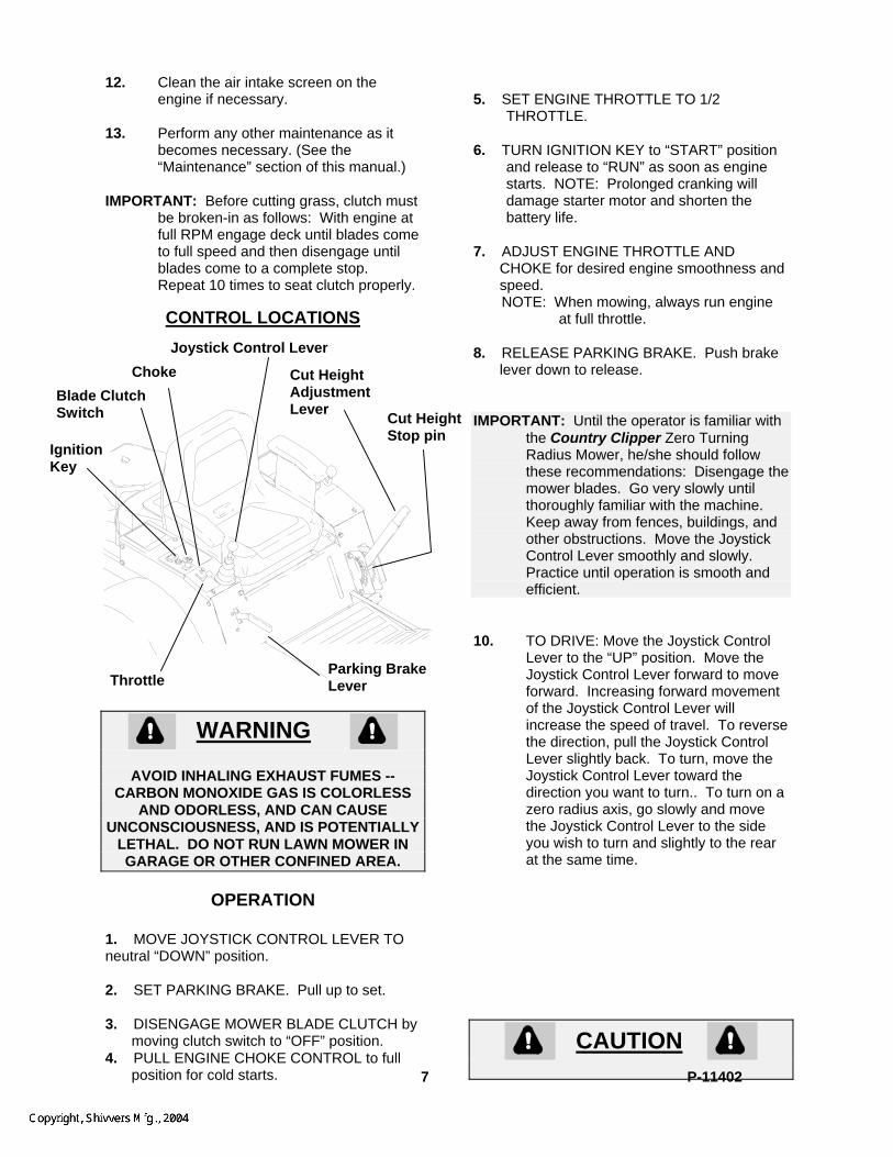
CONTROL LOCATIONS
WARNING
AVOID INHALING EXHAUST FUMES --
CARBON MONOXIDE GAS IS COLORLESS AND ODORLESS, AND CAN CAUSE
UNCONSCIOUSNESS, AND IS POTENTIALLY LETHAL. DO NOT RUN LAWN MOWER IN GARAGE OR OTHER CONFINED AREA.
OPERATION
1. MOVE JOYSTICK CONTROL LEVER TO neutral “DOWN” position. 2. SET PARKING BRAKE. Pull up to set. 3. DISENGAGE MOWER BLADE CLUTCH by
moving clutch switch to “OFF” position. 4. PULL ENGINE CHOKE CONTROL to full
position for cold starts.
5. SET ENGINE THROTTLE TO 1/2
THROTTLE. 6. TURN IGNITION KEY to “START” position
and release to “RUN” as soon as engine starts. NOTE: Prolonged cranking will damage starter motor and shorten the battery life.
7. ADJUST ENGINE THROTTLE AND
CHOKE for desired engine smoothness and speed.
NOTE: When mowing, always run engine at full throttle.
Joystick Control Lever 8. RELEASE PARKING BRAKE. Push brake
lever down to release. IMPORTANT: Until the operator is familiar with
the Country Clipper Zero Turning Radius Mower, he/she should follow these recommendations: Disengage the mower blades. Go very slowly until thoroughly familiar with the machine. Keep away from fences, buildings, and other obstructions. Move the Joystick Control Lever smoothly and slowly. Practice until operation is smooth and efficient.
10. TO DRIVE: Move the Joystick Control
Lever to the “UP” position. Move the Joystick Control Lever forward to move forward. Increasing forward movement of the Joystick Control Lever will increase the speed of travel. To reverse the direction, pull the Joystick Control Lever slightly back. To turn, move the Joystick Control Lever toward the direction you want to turn.. To turn on a zero radius axis, go slowly and move the Joystick Control Lever to the side you wish to turn and slightly to the rear at the same time.
CAUTION
Cut Height Adjustment Lever Cut Height
Stop pin
Blade Clutch Switch
Choke
Ignition Key
Parking Brake Lever Throttle
7 P-11402
FOR SMOOTH, SAFE OPERATION, MOVE THE JOYSTICK CONTROL LEVER IN A
GENTLE, SLOW MOTION. NEVER PULL OR PUSH THE JOYSTICK CONTROL LEVER
RAPIDLY, ESPECIALLY ON GRADES. 11. BRAKING: To brake mower, gently
move the Joystick Control Lever in the direction opposite to travel. If the parking brake is engaged with the Joystick Control Lever in the “UP” position the engine will stop.
12. CUTTING HEIGHT ADJUSTMENT:
With the Cut Height Adjustment Lever latched into the top cut height latch. Insert Cut Height Stop Pin to desired cutting height. Pull Cut Height Adjustment Lever rearward and then to the left to clear top cut height latch. Lower Cut Height Adjustment Lever until it rests on Cut Height Stop Pin.
13. ENGAGE MOWER BLADE CLUTCH:
Set the Blade Clutch Switch to the “ON” position. The engine will not start if the blade clutch is engaged. If the operator is not in the seat, the engine will stop if the clutch is engaged.
CAUTION
AVOID HILL AND SLOPES. USE EXTREME CAUTION WHEN MOWING UP OR DOWN
SLOPES. NEVER MOW ACROSS THE FACE OF A SLOPE. IF A SLOPE MUST BE
ASCENDED, BACK UP THE SLOPE; DRIVE FORWARD WHEN DESCENDING.
14. TO STOP: A. Move Joystick Control Lever to
neutral position and then to the “DOWN” position.
B. Disengage the mower blade clutch by moving the clutch to the “OFF” position.
C. Set the parking brake.
D. Slow engine speed with throttle to slowest position.
E. Turn ignition key to “OFF” (left) position.
F. Remove the key and wait for all movement and all sound to cease before dismounting.
CAUTION
WHEN LEAVING THE MOWER UNATTENDED, ALWAYS REMOVE THE KEY
AND SET THE PARKING BRAKE, EVEN IF JUST FOR A FEW MOMENTS. HELP PROTECT CHILDREN AND OTHER UNAUTHORIZED PERSONS FROM
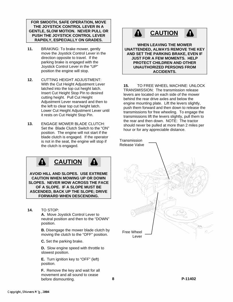
ACCIDENTS. 15. TO FREE WHEEL MACHINE: UNLOCK TRANSMISSION: The transmission release levers are located on each side of the mower behind the rear drive axles and below the engine mounting plate. Lift the levers slightly, push them forward and then down to release the transmissions for free wheeling. To engage the transmissions lift the levers slightly, pull them to the rear and then down. NOTE: The tractor should never be pulled at more than 2 miles per hour or for any appreciable distance. Transmission
Release Valve
Free Wheel Lever
8 P-11402

MOWING RECOMMENDATIONS
1. Keep mower blades sharp. 2. Make sure deck and discharge are
clean.
CAUTION
POWER MUST BE OFF TO CLEAN DISCHARGE CHUTE. TURN ENGINE OFF AND WAIT FOR ALL MOVING PARTS TO
STOP.
3. When mowing tall grass, make two passes, mowing off 1/2 of the desired
cut on the first pass, and then the desired height the second pass. Check for hidden dangers first.
4. Go slowly for trimming. 5. Always cut grass with the engine at full
throttle speed. This “ENGINE” speed allows the cutting blades to operate at optimum cutting speed. Control “GROUND” speed with the Joystick Control Lever.
6. Vary ground speed to suit conditions
(i.e. go slower in tall thick grass, on hills, wet conditions, etc.).
SPECIFICATIONS
TRACTORS Model 2204M 2504M Engine 22 H.P.
Kohler Command
25 H.P. Kohler
Command Hydrostats (2) HydroGear BDU-10L Length 81” Height (to seat back) (to seat cushion)
44” 27”
Width 49” Weight (tractor), approx. 680 lbs. Fuel Tank 11 gallons Belt: Engine - Hydrostats P/N D-3664 Tires, Rear , Front
23-9.50 x 12 13-5.00 x 6
2304KA 23 H.P. KAWASAKI
2304M 23 H.P. Kohler
Command
DECKS Model 5204M 6004M Cutting Width 52” 60” Overall Width (w/chute) 61 ½” 69 ½” Weight (deck), approx. 235 lbs. 236 lbs. Blades (3) 18-3/8” (3) 21” Cutting Height 1-1/2” to 5” Material Thickness 10 ga. Reinforcement Thickness 7 ga. 10 ga Spindle Bearings 25 mm Fits Tractor Models 2204M, 2304M, 2504M AND
2304KA
NOTE: Tractors should be matched to deck to insure sufficient power is available for the intended usage.
9 P-11402

MAINTENANCE
CAUTION
BEFORE PERFORMING ANY MAINTENANCE, TURN OFF ENGINE REMOVE KEY AND DISCONNECT SPARK PLUGS. USE EXTREME CARE WHEN WORKING ON
MACHINERY. DO NOT WEAR WATCHES OR JEWELRY. DO NOT WEAR LOOSE FITTING CLOTHES, AND OBSERVE ALL COMMON SAFETY PRACTICES WITH TOOLS.
MAINTENANCE SCHEDULE
SERVICE WHEN
Check crankcase oil level --------------------------------------------------------------------- before each use Clean grass from Hydrostat fans and cooling fans -------------------------------------- before each use Check air intake screen --------------------------------------------------------------------------- after each use Clean grass under deck -------------------------------------------------------------------------- after each use Check tire pressure ------------------------------------------------------------------------------- every 10 hours Check battery fluid -------------------------------------------------------------------------------- every 10 hours Sharpen mower blades -------------------------------------------------------------------------- every 10 hours Clean air filter pre-cleaner element ----------------------------------------------------------- every 25 hours Check Hydrostatic transmission fluid --------------------------------------------------------- every 25 hours Check drive belts ---------------------------------------------------------------------------------- every 50 hours (20 hours break-in) Service Air Cleaner Filter Element ---------------------------------------------------------- every 100 hours Change engine crankcase oil ------------------------------------------------------------------------- 100 hours oil filter -------------------------------------------------------------------------- 200 hours Change Hydrostat oil and oil filter ----------------------------------------------------------- every 500 hours (100 hours break-in) Replace air filter element --------------------------------------------------------------- annually or 500 hours Check spark plugs ------------------------------------------------------------------------ annually or 500 hours Service battery ---------------------------------------------------------------------------- annually or 500 hours --------------------------------------------------------------------------------------------------------------------------------
Replace decals when illegible. Write factory for free replacement.
10 P-11402

MAINTENANCE INSTRUCTIONS
1. ENGINE: For complete maintenance and
operating information for your engine, please refer to your engine operating and maintenance instructions furnished by the engine manufacturer and included in your Country Clipper Zero Turning Radius Mower information packet.
NOTE: Air intake screen must be kept
clean. If plugged, engine may be seriously damaged by over heating.
2. BATTERY:
CAUTION
BATTERY ELECTROLYTE IS A POISONOUS AND CORROSIVE SULFURIC ACID
SOLUTION. AVOID SPILLING ON SKIN, EYES, AND CLOTHING.
Keep the electrolyte level above the
plates in each cell by adding distilled water as it becomes necessary. Add water just before operating the mower to mix the water with the solution. Be careful not to overfill the battery -- the electrolyte solution is corrosive and can cause damage to surrounding metal parts if it should spill. When taking the battery out of the mower for servicing, make sure to connect the cables to the battery exactly as they were prior to removal. Always disconnect the ground ( - ) wire first and always reconnect the ground ( - ) wire last.
Keep the battery clean. Remove the
corrosion around the battery terminals by applying a solution of one part baking soda to four parts water. Coat all exposed terminal surfaces with a light layer of grease or petroleum jelly to prevent corrosion.
NOTE: At temperatures below 32 degrees F (0
degrees C) the full charge state must be maintained to prevent cell electrolyte from freezing and causing permanent battery damage.
3. TIRES: Correct tire pressure is essential for
efficient operation of the mower. Check tire pressure as requested in the maintenance schedule. Inflate tires to the pressures listed below:
Model Front tires Rear tires All Models
12 psi 12 psi
Lug nuts should be checked regularly
for tightness. 4. MOWER BLADES: Check sharpness of mower blades after
every 10 hours of operation. To sharpen blades proceed as follows:
CAUTION
STOP ENGINE, REMOVE IGNITION KEY AND SPARK PLUGS FOR SAFETY.
A. Remove bolt, lockwasher, and cup
washer mounting blade on shaft. Remove blade.
B. Blades should be discarded when
worn excessively.
DANGEROUS! DO NOT USE
BLADE IN THIS CONDITION
New Blade
C. Sharpen blades with a hand file,
electric grinder or blade sharpener. Wear gloves and eye protection when sharpening. Grind blade at original 25 degree bevel.
25 degrees When notch starts, discard blade
11 P-11402
D. Check balance of blade by positioning the blade on a nail or blade balance pedestal. Grind the blade on the end that is heavier until both sides balance.
E. Install blade, cup washer,
lockwasher, and bolt. Make sure to tighten bolt to 60 ft.lbs.
5. V-BELTS: All belts should be checked every 50
hours. Replace any belts found to be in poor condition. All belts are equipped with spring loaded belt tighteners and do not require tightening adjustments.
6. LUBRICATION: A. Engine: Follow engine
manufacturer’s recommendation. B. Deck Spindles: Lubricate with 3
“shots” only, every 100 hours. C. Hydrostatic Transmission & Filter:
Follow instructions listed below.
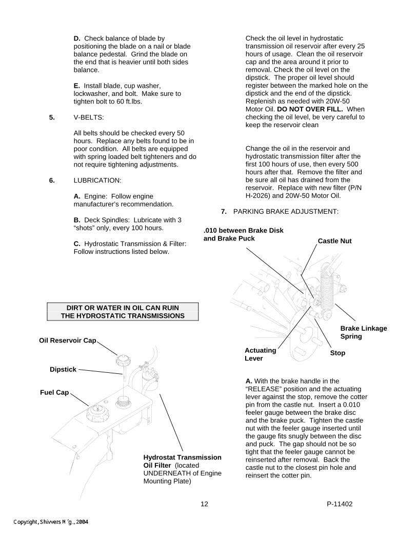
DIRT OR WATER IN OIL CAN RUIN THE HYDROSTATIC TRANSMISSIONS
Check the oil level in hydrostatic transmission oil reservoir after every 25 hours of usage. Clean the oil reservoir cap and the area around it prior to removal. Check the oil level on the dipstick. The proper oil level should register between the marked hole on the dipstick and the end of the dipstick. Replenish as needed with 20W-50 Motor Oil. DO NOT OVER FILL. When checking the oil level, be very careful to keep the reservoir clean
Change the oil in the reservoir and
hydrostatic transmission filter after the first 100 hours of use, then every 500 hours after that. Remove the filter and be sure all oil has drained from the reservoir. Replace with new filter (P/N H-2026) and 20W-50 Motor Oil.
7. PARKING BRAKE ADJUSTMENT:
.010 between Brake Disk and Brake Puck
Castle Nut
Brake Linkage Spring Oil Reservoir Cap
Actuating Lever
Stop
Dipstick A. With the brake handle in the “RELEASE” position and the actuating lever against the stop, remove the cotter pin from the castle nut. Insert a 0.010 feeler gauge between the brake disc and the brake puck. Tighten the castle nut with the feeler gauge inserted until the gauge fits snugly between the disc and puck. The gap should not be so tight that the feeler gauge cannot be reinserted after removal. Back the castle nut to the closest pin hole and reinsert the cotter pin.
Fuel Cap
Hydrostat Transmission Oil Filter (located UNDERNEATH of Engine Mounting Plate)
12 P-11402

8. JOYSTICK CONTROL LEVER NEUTRAL ADJUSTMENT:
With the engine running, if the machine
travels in either direction when the Joystick Control Lever is in the neutral “DOWN” position, stop the engine, elevate the rear wheels clear of the ground and adjust as follows:
A. Remove the right hand fender skirt exposing the Joystick Control Lever Assembly.
B. Start the engine. C. Run engine at fast idle with
Joystick Control Lever in the “DOWN” position.
D. Loosen the locknuts tightened
against the rod end ball joints on the Upper Linkage Assembly that corresponds to the wheel that is turning. Note: One of these is a left hand nut and will have to be turned backwards.
E. Adjust the Neutral Position by
turning the rod in the upper linkage until the wheel stops turning.
F. Retighten the locknuts on upper
linkage assembly and check to make sure the drive wheel is still not turning.
G. Repeat steps B through F for other
side. H. Shut off engine before removing
from blocks. Replace fender skirt. 9. JOYSTICK CONTROL LEVER
DETENT ADJUSTMENT:
If the Joystick Control Lever does not lock in the “UP” position, turn the detent adjustment screw clockwise until a desirable locking action is obtained. If the Joystick control Lever is hard to slide up and down, turn the detent adjustment screw counter-clockwise until a desirable sliding action is obtained.
10. JOYSTICK CONTROL LEVER
SENSITIVITY ADJUSTMENT
To change the sideways turning response adjust as follows: A. Remove the right hand fender skirt exposing the Joystick Control Lever assembly. B. Remove the cross bolt, nut, and spacers C. Reassemble the spacers as desired. (2) spacers between the rod end ball joints and the joystick pivot shaft will quicken the side to side response, (1) spacer slows the response.
NOTE: It is important that there is at least one spacer on each side of the rod end ball joints to prevent damage. Also the small diameter of the spacer must point towards the rod end ball joint.
Spacers (3) per side
Cross Bolt
Joystick Pivot Shaft
L.H. LinkageAssembly
Loosen this nut (Right hand threads)
R.H. Linkage Assembly
Loosen this nut (Left hand threads)
11. ADJUSTING FOR STRAIGHT
FORWARD TRACKING: In a large open area, actuate the
Joystick Control lever into the full forward position. If the mower veers in either direction left or right some adjustment is necessary.
A. If the mower veers to the right, then the right hydrostat needs to be sped up. If the mower veers to the left, then the left hydrostat needs to be sped up.
13 P-11402
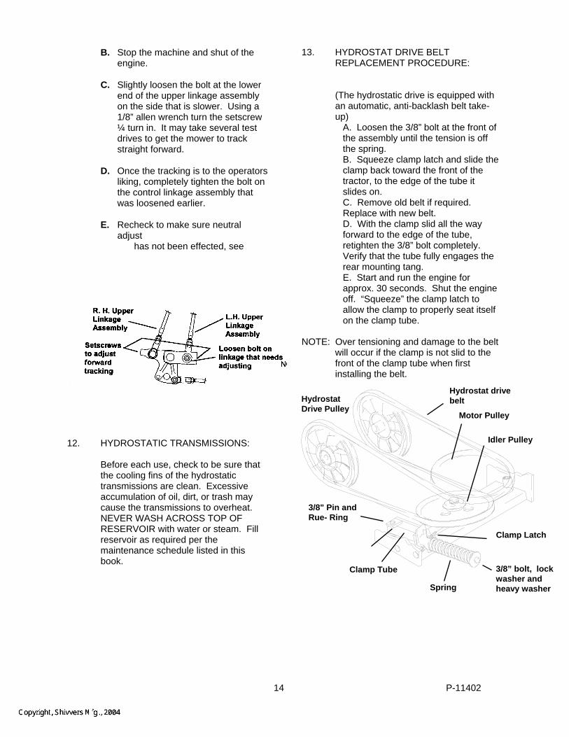
13. HYDROSTAT DRIVE BELT REPLACEMENT PROCEDURE:
B. Stop the machine and shut of the engine.
C. Slightly loosen the bolt at the lower end of the upper linkage assembly on the side that is slower. Using a 1/8” allen wrench turn the setscrew ¼ turn in. It may take several test drives to get the mower to track straight forward.
(The hydrostatic drive is equipped with an automatic, anti-backlash belt take-up)
A. Loosen the 3/8” bolt at the front of the assembly until the tension is off the spring.
B. Squeeze clamp latch and slide the clamp back toward the front of the tractor, to the edge of the tube it slides on.
D. Once the tracking is to the operators liking, completely tighten the bolt on the control linkage assembly that was loosened earlier.
C. Remove old belt if required. Replace with new belt.
D. With the clamp slid all the way forward to the edge of the tube, retighten the 3/8” bolt completely.
E. Recheck to make sure neutral adjust
has not been effected, see
Verify that the tube fully engages the rear mounting tang.
E. Start and run the engine for approx. 30 seconds. Shut the engine off. “Squeeze” the clamp latch to allow the clamp to properly seat itself on the clamp tube.
NOTE: Over tensioning and damage to the belt
will occur if the clamp is not slid to the front of the clamp tube when first installing the belt.
12. HYDROSTATIC TRANSMISSIONS: Before each use, check to be sure that
the cooling fins of the hydrostatic transmissions are clean. Excessive accumulation of oil, dirt, or trash may cause the transmissions to overheat. NEVER WASH ACROSS TOP OF RESERVOIR with water or steam. Fill reservoir as required per the maintenance schedule listed in this book.
Spring
Motor Pulley
Idler Pulley
3/8” bolt, lockwasher and heavy washer
Hydrostat drive belt
Clamp Tube
3/8" Pin andRue- Ring
Hydrostat Drive Pulley
Clamp Latch
14 P-11402
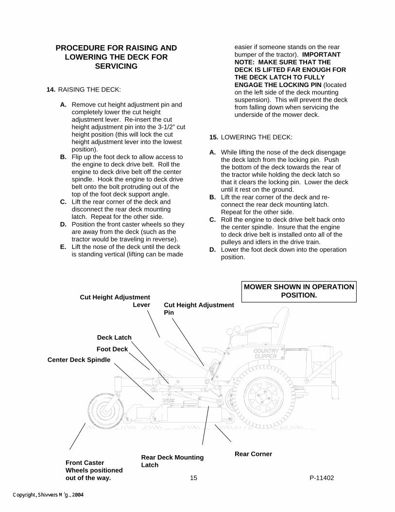
PROCEDURE FOR RAISING AND LOWERING THE DECK FOR
SERVICING 14. RAISING THE DECK:
A. Remove cut height adjustment pin and completely lower the cut height adjustment lever. Re-insert the cut height adjustment pin into the 3-1/2” cut height position (this will lock the cut height adjustment lever into the lowest position).
B. Flip up the foot deck to allow access to the engine to deck drive belt. Roll the engine to deck drive belt off the center spindle. Hook the engine to deck drive belt onto the bolt protruding out of the top of the foot deck support angle.
C. Lift the rear corner of the deck and disconnect the rear deck mounting latch. Repeat for the other side.
D. Position the front caster wheels so they are away from the deck (such as the tractor would be traveling in reverse).
E. Lift the nose of the deck until the deck is standing vertical (lifting can be made
easier if someone stands on the rear bumper of the tractor). IMPORTANT NOTE: MAKE SURE THAT THE DECK IS LIFTED FAR ENOUGH FOR THE DECK LATCH TO FULLY ENGAGE THE LOCKING PIN (located on the left side of the deck mounting suspension). This will prevent the deck from falling down when servicing the underside of the mower deck.
15. LOWERING THE DECK: A. While lifting the nose of the deck disengage
the deck latch from the locking pin. Push the bottom of the deck towards the rear of the tractor while holding the deck latch so that it clears the locking pin. Lower the deck until it rest on the ground.
B. Lift the rear corner of the deck and re-connect the rear deck mounting latch. Repeat for the other side.
C. Roll the engine to deck drive belt back onto the center spindle. Insure that the engine to deck drive belt is installed onto all of the pulleys and idlers in the drive train.
D. Lower the foot deck down into the operation position.
MOWER SHOWN IN OPERATION POSITION.
Cut Height AdjustmentLever
Deck Latch
Foot Deck Center Deck Spindle
Rear Corner
Cut Height Adjustment Pin
Rear Deck Mounting Latch Front Caster
Wheels positioned out of the way.
15 P-11402

MOWER SHOWN IN SERVICING POSITION. Deck Latch in locked
position.Engine to Deck Drive Belt hooked to bolt. Foot Deck in up position
16. LEVELING THE DECK:
A. Set the tire pressure on all four tires B. Move the tractor to a hard, level surface (i.e. concrete or blacktop). Place a 2 x 4 board under
all four corners of the deck shell, just inside of the anti-scalping wheels. Lower the deck down onto the boards. The deck must rest on the boards, NOT the anti-scalping wheels. Adjust the deck hangers longer or shorter until the deck “just” comes off of the boards. Remove the boards and verify that the deck is hanging on all four deck hangers; re-adjust if necessary. Either lengthen both front deck leveling screws three full turns or shorten both rear deck leveling screws three full turns. Lock the jam nuts on the deck hangers. (NOTE: the two rear deck hangers will be easier to adjust if the fender skirts are removed).
Rear Deck Hanger, one each side
Front Deck Hanger, one each side
2 x 4 board, One each corner, just inside of anti-scalping wheel
16 P-11402

TROUBLE SHOOTING CHECK LIST
1. ENGINE WON’T TURN OVER: Mower blades engaged ------------------------------------------------- disengage blades Drive not in neutral --- move Joystick Control Lever to neutral “DOWN” position Blown fuse ------------------------------------------------------------------------ replace fuse Dead battery --------------------------------------------------------------- charge or replace Solenoid ------------------------------------------------------------------------- consult dealer Ignition switch ------------------------------------------------------------------ consult dealer Starter ---------------------------------------------------------------------------- consult dealer 2. ENGINE WILL TURN OVER BUT WON’T START: No gas -------------------------------------------------------------------------------------- refuel clean or replace fuel filters Over or under choked --------------------------------------------------------- adjust choke Spark plug not firing ------------------------------------------------------ check spark plug condition and reset gap* Carburetor maladjustment ------------------------------- reset carburetor adjustment* Ignition switch ------------------------------------------------------------------ consult dealer 3. HARD TO START ENGINE: Fuel line clogged ----------------------------------- clean fuel line and check fuel filter Faulty fuel pump -------------------------------------------------------------- consult dealer Spark plug wire loose or grounded ---------------------------- check spark plug wires Spark plug(s) faulty or improperly gapped -------------------------- check spark plug condition and reset gap* Electronic ignition defective ------------------------------------------------ consult dealer Dirty or maladjusted carburetor ------------------------------------- readjust carburetor* consult dealer for carburetor service 4. ENGINE STARTS BUT CUTS OUT: Water in gasoline ---------------- drain old gasoline and replace with new gasoline clean carburetor bowl Clogged fuel line ------------------------------------------------------------- check fuel filter clean fuel line Vent in fuel cap plugged --------------------------------------------------------- check vent Faulty fuel pump -------------------------------------------------------------- consult dealer Maladjusted carburetor ----------------------------------------------- readjust carburetor* Engine dies when Joystick Control Lever is pulled “UP” -------- parking brake set release brake 5. ENGINE KNOCKS: Low oil level --------------------------------------------------------------- check and add oil Ignition timing off ------------------------------------------------------------- consult dealer fuel octane too low ------------------------------------------------- drain and replace with higher octane gasoline Over heated engine ---------------------------------- shut off engine and allow to cool
* See engine manual for engine adjustments.
17 P-11402

6. ENGINE SOMETIMES SKIPS AT HIGHER SPEEDS: Incorrect Ignition Timing ---------------------------------------------------- consult dealer Carburetor maladjusted ----------------------------------------------- readjust carburetor Faulty spark plugs --------------------------------------------------------- check spark plug condition and reset gap* Bouncing off seat safety switch -------------------------- slow down on rough terrain 7. ENGINE OVER HEATED: Air intake screen or fins clogged ------------------------ clean intake screen and fins Fuel mixture too lean ------------------------------------------------- readjust carburetor* Oil level too low or too high ------------------------------------------------ adjust oil level Improper ignition timing ----------------------------------------------------- consult dealer Running engine too slow ------------------------------------------------ run engine faster (NOTE: Always mow at full throttle setting.) 8. ENGINE IDLES POORLY: Carburetor maladjustment -------------------------------------------- readjust carburetor Improper spark plug gap ---------------------------------------- check and re-gap plug* 9. ENGINE BACKFIRES: Carburetor maladjustment ------------------------------------------ readjust carburetor* 10. ENGINE RUNS BUT MOWER WON’T MOVE FORWARD: Drive belt broken or slipping ------------------------------------------- replace drive belt Shift linkage cable disconnected ----------------------------------------------- reconnect Transmission shift arm disconnected ----------------------------------------- reconnect Transmission oil low ------------------------------------------------------------------- add oil Transmission locks in free wheel position --------- put in lock position (see pg. 8) Hydrostat oil filter plugged ---------------------------------------------------- replace filter Bad transmission -------------------------------------------------------------- consult dealer Gear mating transmission/gearbox disconnected --------------------- consult dealer 11. MOWER LOSES POWER OR TRANSMISSIONS OVER HEATS: Hydrostat transmission oil too low or too high ---------------------------------- add oil OR drain oil as needed Transmission damage ------------------------------------------------------- consult dealer Transmission blowing oil out cap ------------------------------------ overfilled or water contaminated 12. ENGINE STALLS WHEN BLADES ARE ENGAGED: Operator not on seat -------------------------------------------------------------- sit on seat Faulty interlock system ------------------------------------------------------ consult dealer Bad blade spindle bearing -------------------------------------------------- consult dealer Deck drive belt not properly routed ------------------------------------------------ reroute Blades blocked by foreign material ----------------------------------- clean under deck
* See engine manual for engine adjustments.
18 P-11402

WIRING SCHEMATIC: 22, 23 & 25 H.P. MODELS
Note: All wire connectors shown at wire side.
START SWITCH POSITION CIRCUIT “MAKE
OFF G+M ON B+L
START B+L+S
Black wires = Ground Red wires = Power Blue wires = Kill Circuit Yellow wires = Start Circuit Green wires = Signal Circuit
19 P-11402