safety relay nd1/2-d - carlo gavazzi | gavazzi … safety relay nd1/2-d can be used in applications...
TRANSCRIPT

SAIET Elettronica S.p.A. - A Member of CARLO GAVAZZI Groupvia Serenari, 1 - 40013 Castel Maggiore (BO), Italy
Tel. +39 051 4178811 - Fax +39 051 4178800http://www.saiet.it/elettronica E-mail:[email protected]
SAFETY RELAYND1/2-D
User’s Manual
Gross Automation (877) 268-3700 · www.carlogavazzisales.com · [email protected]

Index
1. INTRODUCTION..........................................................................3
2. SAFETY INDICATIONS...............................................................3
3. ASSEMBLY AND FUNCTION......................................................4
3.1 Power supply terminals ........................................................4
3.2 Input terminals ......................................................................43.3 Function................................................................................4
4. MOUNTING AND OPENING .......................................................5
5. ELECTRONIC CONNECTION.....................................................6
5.1 Power supply ........................................................................65.2 Close the feedback control loop and the input circuit. ..........6
5.3 PNP auxiliary output .............................................................6
6. MAINTENANCE AND REPAIR ....................................................7
7. FAULT DIAGNOSIS.....................................................................8
8. WIRING HINTS FOR OUTPUT TERMINALS..............................8
9. TECHNICAL DATA ......................................................................8
Gross Automation (877) 268-3700 · www.carlogavazzisales.com · [email protected]

1. INTRODUCTION
This operating instruction isreferred to the two-hand devicesmonitoring relay ND1/2-D (24Vac/dc) and to the modelssupplied with an AC power supply and named ND1/2-D/xxx (wherexxx is the AC supply voltage).
The ND1/2-D name, used in thismanual, is referred to all themodels (DC and AC supply), if not differently specified.
These instructions are addressedto the following persons:
• Qualified professionals whoplan and develop safetyequipment for machines andplants and who are familiar with the safety instructions andsafety regulations.
• Qualified professionals, whoinstall safety equipment intomachines and plants and putthem into operation.
The operating instructionscontains several symbols whichare used to highlight importantinformation.
WARNINGü This word is placed in front of
text which has to be absolutelypaid attention to.Nonobservance leads toserious injuries or damage toproperty.
IMPORTANTü This word is placed in front of
text which contains importantinformation.
ACTIVITYü This word is placed in front of
activities.
RESULTü After this word follows a
description on how the situation has changed after an activity isperformed.
2. SAFETY INDICATIONS
Application
The safety relay ND1/2-D can beused in applications for Two-Hand control according to EN 574 up tolevel IIIc.
IMPORTANTü Person and object protection
are not guaranteed, if the safety relay is not used according tothe defined application.
WARNINGFOR YOUR SAFETY!
Please, note the following points:
ü The unit should only beinstalled and operated bypersons who are familiar withboth these instructions and thecurrent regulations for safety atwork and accident prevention.Electrical works may beexecuted only by electricalspecialist.
ü Follow local regulations asregards preventative measures.
3Gross Automation (877) 268-3700 · www.carlogavazzisales.com · [email protected]

ü Starting the machine whilestanding in the dangerous areamust be impossible.
ü Any guarantee is void followingopening of the housing orunauthorized modifications.
ü Avoid mechanical vibrationsgreater than 5 g / 33 Hz whentransporting and in operations.
ü The unit should be panelmounted in an enclosure ratedat IP 54 or better, otherwisedampness or dust could lead tofunction impairment.
ü Adequate fuse protection mustbe provided on all output safetycontacts with capacitive and / or inductive loads.
3. ASSEMBLY ANDFUNCTION
3.1 Power supply terminalsThe supply voltage must beapplied to the terminals A1 and
A2. The POWER LED illuminates.
3.2 Input terminalsThe input terminals S11, S12, S21 and S22 have to be wired up tothe two-hand control device asshown in the connection diagrams of this user’s manual.
3.3 FunctionThe unit is enabled to start whenthe two switches S1 & S2 areoperated with a delay lower than0.5 seconds (see Fig. 1). At thistime, the safety outputs 13-14, 23-24 and the PNP auxiliary output34 close immediately, while theauxiliary contact 31-32 opensimmediately.
The LEDs Channel 1 andChannel 2 illuminate.
If one or both buttons arereleased, the safety outputs 13-14, 23-24 and the PNP auxiliaryoutput 34 open immediately, while the auxiliary contact 31-32 closes
4
Fig. 1 - Timings
Gross Automation (877) 268-3700 · www.carlogavazzisales.com · [email protected]

immediately. The LEDs Channel1 and/or Channel 2 turn off.
A new cycle can be started onlyafter releasing both S1 & S2switches and if the feedbackcontrol loop contacts are closed(external contactors de-energized).
4. MOUNTING ANDOPENING
The unit should be panel mounted in an enclosure rated at IP 54 orbetter, dust and humidityprotected, because dampness ordust could lead to functionimpairment.
5
Terminal Function / ConnectionA1 +24VDC or AC supply
A2 GND or AC supply
S11, S12, S22 First input button (S1)
S21, S12, S22 Second input button (S2)
Y1-Y2 Feedback control loop
34 PNP aux output (collector of a PNP transistor with emitterconnected internally to Vcc)
13-14 First safety output (N.O.)
23-24 Second safety output (N.O.)
31-32 Relay auxiliary output (N.C.)
Fig. 2 - Functional circuit diagram of ND1/2-D relay
Gross Automation (877) 268-3700 · www.carlogavazzisales.com · [email protected]
ACTIVITYü There is a notch on the rear of
the unit for DIN-Rail mounting.
Carry out the wire appropriate tothe use of the unit, according to
the technical data of this user’smanual.5. ELECTRONIC
CONNECTION
5.1 Power supplyConnect the power supply to A1and A2 terminals.
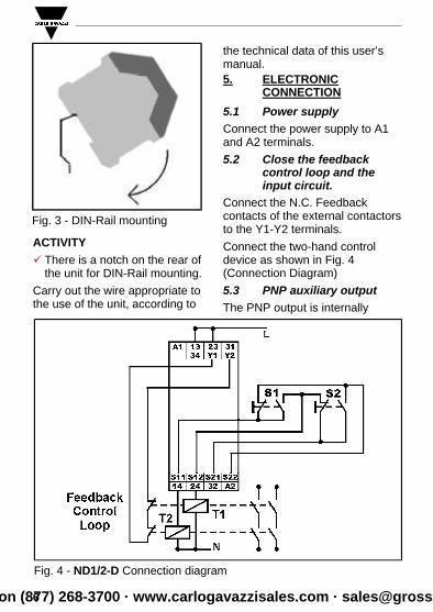
5.2 Close the feedbackcontrol loop and theinput circuit.
Connect the N.C. Feedbackcontacts of the external contactors to the Y1-Y2 terminals.
Connect the two-hand controldevice as shown in Fig. 4(Connection Diagram)
5.3 PNP auxiliary outputThe PNP output is internally
6
Fig. 4 - ND1/2-D Connection diagram
Fig. 3 - DIN-Rail mounting
Gross Automation (877) 268-3700 · www.carlogavazzisales.com · [email protected]

connected to the +24 Vcc. Onterminal 34 is available thecollector of the PNP transistor.Connect to the 34 terminal anexternal resistive load withR≥2400 Ohm (see fig. 3).
Connect the ground of the PNPexternal circuit to:
• A2 terminal, if the safety relay is powered with 24 Vdc supply;
• S12 (internal ground) terminal if the relay is powered with an AC supply.
WARNINGü Please, note the maximum
length of the cables! 6. MAINTENANCE AND
REPAIR
The safety relay ND1/2-D ismaintenance-free.
7
Fig. 6 - Change of the ND1/2-D safety relay
Fig. 5 - Connection of the auxiliary PNP output
Gross Automation (877) 268-3700 · www.carlogavazzisales.com · [email protected]

In event of failure, it is possible tochange the defective device witha new one following the stepsdescribed below:
ü Switch off the relay and remove the wiring from the device.
ü Take off the defective devicefrom the DIN-Rail.
üMount the new device on theDIN-Rail.
ü Insert and fix the cables on thenew device.
7. FAULT DIAGNOSIS
Earth Fault (AC/DC version with electronic fuse protection).
An electronic fuse forces theoutput contacts to open. As soonas the fault cause is removed, and the rated power supply is applied,the device is ready for newoperations.
Faulty contact conditionIn the event of welded contacts,further activation is not possiblefollowing the opening of the inputcircuit.
Only one or no LED illuminates
External wiring or internal fault ispresent.
Check the external wiring andrestart the safety relay.
If the fault is still present, contactSAIET Elettronica.
8. WIRING HINTS FOROUTPUT TERMINALS
The positive power supply voltage (for example L or 24 VDC, but notGND) should be routed via theoutput terminals. This will help torecognize shorts to GND or Earth.
Using R-C combination in parallelwith inductive loads (for examplecoils of the external contactors)can reduce the wearing out of theoutput contacts.9. TECHNICAL DATA
See the following tables.
8Gross Automation (877) 268-3700 · www.carlogavazzisales.com · [email protected]

9
ELECTRICAL DATA VALUES
Power supply voltage (Uv) 24 VDC (Elec.fuse protect) or AC supply
Voltage range 0.85 ... 1.1 UvFrequency (AC Type) 50 - 60 HzPower Consumption (Approx.) 2 VA / 2 W CONDUCTORS DATA VALUES
Conductor connection 0.14 ÷ 2.5 mm2 Rigid Wire0.14 ÷ 2.5 mm2 Flexible Wire
Max Conductor Length (inputcircuit, cross-section = 1.5 mm2) 4x150 m (@+55°C)
Max. capacity of input cables 150 nF/kmCONTACTS DATA VALUESSafety Contacts 2 N.O.
Aux. Contact 1 N.C. Relay output 1 N.O. PNP output
Safety & N.C.Aux.Contact type Forced Guided RelaysContact Material AgSnO2 or comparableSwitching voltage 250 VAC , 24 VDC
Switching current 6AMax switching capacity 1500 VA (ohms load)Mechanical lifetime 107 cyclesElectrical lifetime 105 cyclesCreeping distance andclearance (DIN VDE 0160)(DIN VDE 0110)
Pollution degree: 2.Basis insulation: Overvoltage
Category: 3/250 VProtective Separation: Ov. Cat. 2
Contact security(DIN VDE 0660 - Part 200) 6 A fast or 4 A slow
Voltage at S11 terminal 24 VDC
Delay on de-energization < 30 msMax delay between inputs 0.5 sec.
Gross Automation (877) 268-3700 · www.carlogavazzisales.com · [email protected]

10
AUXILIARY PNP OUTPUT VALUESSupply voltage of the relay > 18 VDC
Resistive load ≥ 2400 OhmMECHANICAL DATA VALUES
Housing Material Polyamid PA6.6Dimensions (WxHxP) 22.5 x 114.5 x 99Fastening Click-fastening for DIN-rail
ENVIRONMENTAL DATA VALUESOperating Temperature -25°C .... + 55°CMax. Humidity Alt. Cycle: 95% / 0-50 °C Terminal type (DIN VDE 0470 Part 1) IP 20Housing type (DIN VDE 0470 Part 1) IP 40Shock resistance (DIN VDE 0160) 5g, 33 Hz
Gross Automation (877) 268-3700 · www.carlogavazzisales.com · [email protected]

11Gross Automation (877) 268-3700 · www.carlogavazzisales.com · [email protected]

12
SAIET reserves the right to make improvements or changes without prior notice.
Gross Automation (877) 268-3700 · www.carlogavazzisales.com · [email protected]