saldatura damage investigation on welded tubes of a ... · pdf filedamage investigation on...
TRANSCRIPT

La Metallurgia Italiana - n. 1/2015 53
Saldatura
E. Guglielmino, A. SiliDipartimento di Ingegneria Elettronica, Chimica e
Ingegneria Industriale – Università di Messina
R. PinoRaffineria di Milazzo S.C.p.A
C. ServettoIIS Service Srl, Genova
Damage investigation on welded tubesof a reforming furnace
E. Guglielmino, R. Pino, C. Servetto, A. Sili
Keywords: Superalloys - Welding - Non-destructive testing - Mechanical testing -Metallography - Electron microscopy
In this work the creep damage of radiant tubes of a reforming furnace has been investigated. The considered furnace contains a battery of tubes constructed by butt welding three spun cast pieces, made of ASTM 608 HP-Nb alloy.
They are designed to operate at temperatures of about 900°C, pressures of about 30 bars and times of the order of 100000 h. Tubes were inspected during the plant stops scheduled every two years, in order to identify and replace the damaged ones with the aim to ensure conditions of safe operation in the furnace. They were selected though a criterion based on measures of the internal diameter deformation performed in situ by Laser Optic Tube Inspection System (LOTIS). For a verification of this method, optical and scanning electron microscopy observation, Vickers
microharndess and creep tests have been carried out on samples taken from tubes put out of service.
INTRODUCTION
During service at high temperature and for long time, me-tallic materials undergo to different levels of creep phe-nomena, which lead first to slow deformations and finally to crack nucleation and propagation. These conditions are particularly dangerous in the case of piping and pressure devices. In order to verify every compliance with safety conditions and working reliability, the operational practice is based on a series of control activities. Investigations on life conditions of pressure vessels are addressed both to identify premature failures and avoid, even if their safe working can still be fully guaranteed, to put them out ser-vice for attainment of the design life, previously evaluated on the basis of conservative criteria.In this work we investigate the radiant tubes of a furnace for the hydrogen production from methane and water va-por by means of the endothermic reforming reaction that take place thanks to a granular Ni-based catalyst.The furnace here considered is a chamber, coated inside by refractory material, containing 4 parallel rows of 44 vertically hung radiant tubes (Fig. 1). These tubes are con-structed by butt welding three spun cast pieces, made of a Ni-Cr-Fe alloy. Radiant tubes, heated from the outside by
means of a system of gas burners, operate at temperature of about 900°C and pressure of 33 bar, for times of the order of 100000 hours.Service temperature and tensile circumferential stress, due to the internal pressure, give rise to a severe creep conditions that led to diameter expansion [1]; inside tubes there are carburizing conditions, however unforeseen catastrophic failure may be accelerated by local oxidative phenomena [2].Two examples of tube damage are given here: the yellow arrows in figure 2a indicates a tube section that under-went creep expansion; figure 2b shows a large longitudinal crack across a butt welded joint.
Fig. 1 – Assembly of a tubes row (a) and detail of a single tube (b). The arrows indicate the gas flows
entering and leaving the tube.
a) b)

La Metallurgia Italiana - n. 1/201554
Memorie
Therefore good mechanical properties and corrosion resis-tance at high temperature are requested for radiant tube alloys [3]. These materials have seen significant improve-ments during the last fifty years: in the 60s and 70s the al-loy 25Cr-20Ni-Fe-0.4C, designated as HK-40, was the most utilized, while in the following decades the HP-40 alloy (25Cr-35Ni-Fe-0.4C-1.5Si) has been widely considered [4]. The high concentrations of Cr and Ni give great mechanical strength and corrosion resistance at service temperature, the presence of Si improves carburization resistance. The mechanical reinforcement of the HP-40 alloy is obtained by a dispersion of carbides particles with high hardness [5] whose stability is decisive for creep behavior [6]. Moreover, because it has been tested that microalloying elements are able to stabilize a fine dispersion of carbides, starting from the 90s HP-40 alloys have been developed with addition of Nb (about 1%) [7], Ti (up to about 0.8%) [8] and Y (about 0.3% [9] to improve their creep behavior.Tubes life is shortened by creep damage, being character-ized by progressive microstructural changes [10], as car-bides transformations, microcracks nucleation and forma-tion of voids, typical of the final creep stage that precedes fracture [11, 12].Unfortunately, during the furnace scheduled stop, tubes have to be decommissioned to cut metallographic sam-ples and perform microscopic observations and me-chanical test. However, because each single tube is very expensive and its damage conditions are not necessar-ily representative of the other tubes, many experimental works have been addressed to non destructive methods, such as eddy current and ultrasonic measurements [13, 14, 15]. Moreover, being these investigations affected by many uncertainties, studies on the relationship between microstructural degradation and mechanical properties are largely quoted in literature [2, 11, 16]. In this respect it is worth noting that the residual life evaluation depends on actual service temperatures (measured by optical pyrom-eters with an error of +/- 20 °C), mechanical properties values after long time service, actual stress state and ther-
Fig. 2 – Examples of radiant tube damage: a) creep expansion of a tube section; b) large longitudinal crack across a butt welded joint.
mal cycles associated to the furnace start-up and shut-down. So adequate means of investigation giving reliable information about tubes damage are required.Nowadays reforming furnaces rely on the Laser Optic Tube Inspection System (LOTIS), a non-destructive control tech-nique based on creep deformation measures performed in situ by driving a laser probe inside tubes [17]. It is very promising for the development of a criterion for decom-missioning tubes that would be no longer safe until the next scheduled stop [18]. So furnaces have to be regularly inspected during each stop, in order to identify the dam-aged components and replace them. The radiant tubes are visually observed with the aim of identifying macro-scopic damage; creep deformations are detected through LOTIS measures in order to select the tubes to put out of service for safety reasons.In previous works [18, 19] laboratory tests were carried out to correlate mechanical properties and microstructur-al changes in tubes decommissioned after long time ser-vice. In this paper the experimental investigations have been extended to the butt welds that join the tube pieces. Samples for creep tests and microstructural observations were cut from various sections also including welds.
MATERIALS AND METHODS
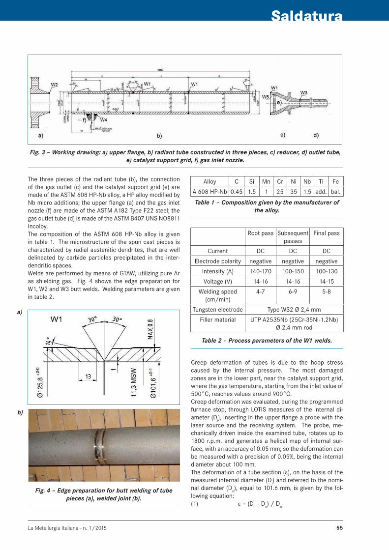
As shown in the working drawing (Fig. 3), radiant tubes are constructed in three butt welded pieces (W1 welds); the first one (located in the upper vertical position inside the furnace) is welded to the upper flange (W2), the third one is welded to the reducer (W1), in turn welded to the outlet tube (W3); other welds concern the gas inlet nozzle (W4) and the catalyst support grid (W5).Radiant tubes have an internal diameter of 101.6 mm, a nominal thickness of 10.5 mm and an overall length of 12.8 m. The design conditions are pressure of 32.7 bar and temperature of 950°C, while the operating tempera-ture is 900°C.
a) b)
La Metallurgia Italiana - n. 1/2015 55
Saldatura
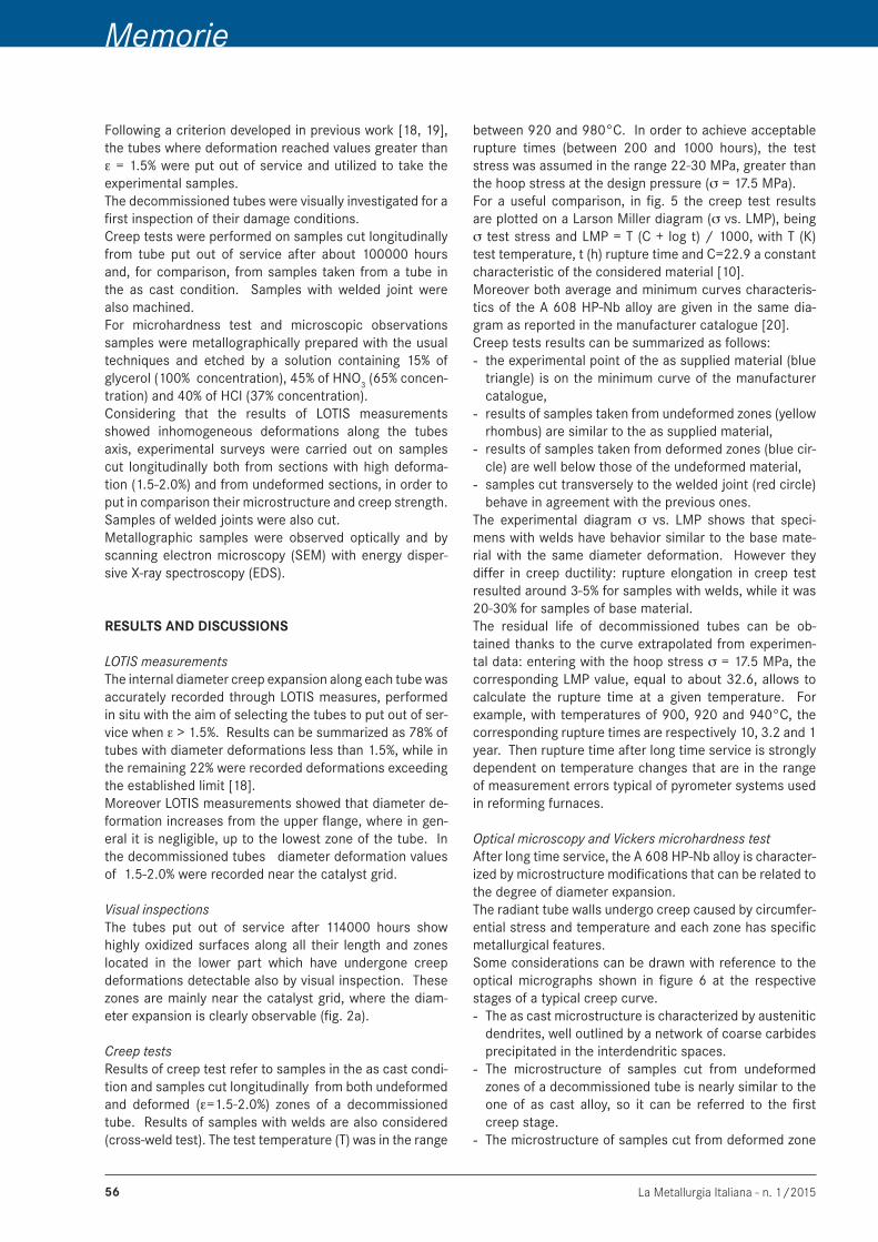
The three pieces of the radiant tube (b), the connection of the gas outlet (c) and the catalyst support grid (e) are made of the ASTM 608 HP-Nb alloy, a HP alloy modified by Nb micro additions; the upper flange (a) and the gas inlet nozzle (f) are made of the ASTM A182 Type F22 steel; the gas outlet tube (d) is made of the ASTM B407 UNS NO8811 Incoloy.The composition of the ASTM 608 HP-Nb alloy is given in table 1. The microstructure of the spun cast pieces is characterized by radial austenitic dendrites, that are well delineated by carbide particles precipitated in the inter-dendritic spaces. Welds are performed by means of GTAW, utilizing pure Ar as shielding gas. Fig. 4 shows the edge preparation for W1, W2 and W3 butt welds. Welding parameters are given in table 2.
Fig. 3 – Working drawing: a) upper flange, b) radiant tube constructed in three pieces, c) reducer, d) outlet tube, e) catalyst support grid, f) gas inlet nozzle.
Alloy C Si Mn Cr Ni Nb Ti Fe
A 608 HP-Nb 0.45 1.5 1 25 35 1.5 add. bal.
Table 1 – Composition given by the manufacturer of the alloy.
Root pass Subsequent passes
Final pass
Current DC DC DC
Electrode polarity negative negative negative
Intensity (A) 140-170 100-150 100-130
Voltage (V) 14-16 14-16 14-15
Welding speed (cm/min)
4-7 6-9 5-8
Tungsten electrode Type WS2 Ø 2,4 mm
Filler material UTP A2535Nb (25Cr-35Ni-1.2Nb)Ø 2,4 mm rod
Table 2 – Process parameters of the W1 welds.
Creep deformation of tubes is due to the hoop stress caused by the internal pressure. The most damaged zones are in the lower part, near the catalyst support grid, where the gas temperature, starting from the inlet value of 500°C, reaches values around 900°C.Creep deformation was evaluated, during the programmed furnace stop, through LOTIS measures of the internal di-ameter (Di), inserting in the upper flange a probe with the laser source and the receiving system. The probe, me-chanically driven inside the examined tube, rotates up to 1800 r.p.m. and generates a helical map of internal sur-face, with an accuracy of 0.05 mm; so the deformation can be measured with a precision of 0.05%, being the internal diameter about 100 mm.The deformation of a tube section (ε), on the basis of the measured internal diameter (Di) and referred to the nomi-nal diameter (Do), equal to 101.6 mm, is given by the fol-lowing equation:(1) ε = (Di – Do) / Do
Fig. 4 – Edge preparation for butt welding of tube pieces (a), welded joint (b).
a)
b)
La Metallurgia Italiana - n. 1/201556
Memorie
Following a criterion developed in previous work [18, 19], the tubes where deformation reached values greater than ε = 1.5% were put out of service and utilized to take the experimental samples.The decommissioned tubes were visually investigated for a first inspection of their damage conditions.Creep tests were performed on samples cut longitudinally from tube put out of service after about 100000 hours and, for comparison, from samples taken from a tube in the as cast condition. Samples with welded joint were also machined.For microhardness test and microscopic observations samples were metallographically prepared with the usual techniques and etched by a solution containing 15% of glycerol (100% concentration), 45% of HNO3 (65% concen-tration) and 40% of HCl (37% concentration).Considering that the results of LOTIS measurements showed inhomogeneous deformations along the tubes axis, experimental surveys were carried out on samples cut longitudinally both from sections with high deforma-tion (1.5-2.0%) and from undeformed sections, in order to put in comparison their microstructure and creep strength. Samples of welded joints were also cut.Metallographic samples were observed optically and by scanning electron microscopy (SEM) with energy disper-sive X-ray spectroscopy (EDS).
RESULTS AND DISCUSSIONS
LOTIS measurementsThe internal diameter creep expansion along each tube was accurately recorded through LOTIS measures, performed in situ with the aim of selecting the tubes to put out of ser-vice when ε > 1.5%. Results can be summarized as 78% of tubes with diameter deformations less than 1.5%, while in the remaining 22% were recorded deformations exceeding the established limit [18]. Moreover LOTIS measurements showed that diameter de-formation increases from the upper flange, where in gen-eral it is negligible, up to the lowest zone of the tube. In the decommissioned tubes diameter deformation values of 1.5-2.0% were recorded near the catalyst grid.
Visual inspectionsThe tubes put out of service after 114000 hours show highly oxidized surfaces along all their length and zones located in the lower part which have undergone creep deformations detectable also by visual inspection. These zones are mainly near the catalyst grid, where the diam-eter expansion is clearly observable (fig. 2a).
Creep tests Results of creep test refer to samples in the as cast condi-tion and samples cut longitudinally from both undeformed and deformed (ε=1.5-2.0%) zones of a decommissioned tube. Results of samples with welds are also considered (cross-weld test). The test temperature (T) was in the range
between 920 and 980°C. In order to achieve acceptable rupture times (between 200 and 1000 hours), the test stress was assumed in the range 22-30 MPa, greater than the hoop stress at the design pressure (σ = 17.5 MPa).For a useful comparison, in fig. 5 the creep test results are plotted on a Larson Miller diagram (σ vs. LMP), being σ test stress and LMP = T (C + log t) / 1000, with T (K) test temperature, t (h) rupture time and C=22.9 a constant characteristic of the considered material [10].Moreover both average and minimum curves characteris-tics of the A 608 HP-Nb alloy are given in the same dia-gram as reported in the manufacturer catalogue [20].Creep tests results can be summarized as follows:
the experimental point of the as supplied material (blue - triangle) is on the minimum curve of the manufacturer catalogue,results of samples taken from undeformed zones (yellow - rhombus) are similar to the as supplied material,results of samples taken from deformed zones (blue cir-- cle) are well below those of the undeformed material,samples cut transversely to the welded joint (red circle) - behave in agreement with the previous ones.
The experimental diagram σ vs. LMP shows that speci-mens with welds have behavior similar to the base mate-rial with the same diameter deformation. However they differ in creep ductility: rupture elongation in creep test resulted around 3-5% for samples with welds, while it was 20-30% for samples of base material.The residual life of decommissioned tubes can be ob-tained thanks to the curve extrapolated from experimen-tal data: entering with the hoop stress σ = 17.5 MPa, the corresponding LMP value, equal to about 32.6, allows to calculate the rupture time at a given temperature. For example, with temperatures of 900, 920 and 940°C, the corresponding rupture times are respectively 10, 3.2 and 1 year. Then rupture time after long time service is strongly dependent on temperature changes that are in the range of measurement errors typical of pyrometer systems used in reforming furnaces.
Optical microscopy and Vickers microhardness testAfter long time service, the A 608 HP-Nb alloy is character-ized by microstructure modifications that can be related to the degree of diameter expansion. The radiant tube walls undergo creep caused by circumfer-ential stress and temperature and each zone has specific metallurgical features. Some considerations can be drawn with reference to the optical micrographs shown in figure 6 at the respective stages of a typical creep curve.
The as cast microstructure is characterized by austenitic - dendrites, well outlined by a network of coarse carbides precipitated in the interdendritic spaces.The microstructure of samples cut from undeformed - zones of a decommissioned tube is nearly similar to the one of as cast alloy, so it can be referred to the first creep stage.The microstructure of samples cut from deformed zone -

La Metallurgia Italiana - n. 1/2015 57
Saldatura
Fig. 5 – Creep test results: Larson Miller diagram.
(ε = 1.5-2.0%) is characterized by a precipitation of fine secondary carbides inside the austenitic grains, optically observable at high magnification, and by nearly circular isolated microvoids.
Isolated microvoids appear during the steady state creep. In particular the absence of aligned microvoids, formed by the coalescence of two or more microvoids [21], can be considered as an indication that the final creep stage has not yet started. In welded sections, no evidence of particular structures was detected at the boundary between base metal and molten zone (fig. 7). The latter appears to be character-ized by very fine carbides aligned with the heat flow direc-tion.Regarding microhardness survey, it was noticed a remark-able softening after 114000 hours of service compared to values of about 400HV measured in the as cast mate-rial: microhardness values through base metal and molted zone are around 180 HV (fig. 8).
SEM and EDS investigationsMicrostructural changes in samples taken from deformed zones of a decommissioned tube respect to the as cast alloy are investigated by SEM observations and EDS meas-urements too.In the as cast alloy, two kind of precipitates at the austenit-ic grain boundaries are clearly observable: a grey phase, with greater volume fraction, and a phase in the form of small white particles. The EDS spectra allow to recognize the grey phase as Cr carbide, while the small white parti-cles are rich of Nb and Si.In samples taken from deformed zones, grey precipitates are located both inside grains and at their boundaries (fig. 9). These particles are recognized as Cr carbide through EDS measurements. The HP alloys underwent phase transformations due to thermal activation during service at temperatures between 1123 and 1325 K and primary Cr carbides M7C3, instable at high temperature, transform into intragranular and intergranular M23C6 precipitates [23]. Another change regards the white precipitates at grain boundary that in deformed samples have dimension and volumetric fraction greater than in the as cast alloy; more-
Fig. 6 – Microstructures of the ASTM 608 HP-Nb alloy, in relation to the respective level of creep
deformation. In the case of material after 114000 hours of service it can be outlined: a) fine carbide
precipitation inside grains, b) primary carbide at grain boundary, c) nearly circular microvoids.
Fig. 7 – Optical micrograph of the boundary between molten zone and base metal in a welded joint (tube
decommissioned after 114000 hours).
Fig. 8 – Vickers microhardness (200g -15s) in a welded section (tube put out of service after 114000 hours).
over EDS measurements give high concentrations of Nb, Ni, Si. As quoted in literature [33, 34], Nb carbides are not stable in the range of service temperatures, between 700 and 900°C, transforming into Ni-Nb silicates known as G-phase. Unlike the Nb carbides that give good creep properties, the G-phase coarsening is followed by reduc-tion of creep resistance [3]: this negative effects can be

La Metallurgia Italiana - n. 1/201558
Memorie
ascribed to the interface between G-phase and matrix that becomes a preferential site for creep damage [7]. Luck-ily this phenomenon can be overlooked in the HP grades microalloyed with small quantities of Ti, that reduce the G-phase volume fraction [7].
CONCLUSIONS
The experimental investigations carried out on radiant tubes, made of ASTM 608 HP-Nb alloy and installed in a reforming furnace, have confirmed that LOTIS measure-ments of the internal diameter give good indications on the degree of creep damage and allow to select the tubes to put out of service.Creep tests and metallographic observations have shown that samples taken from undeformed section are free of damage and have characteristics similar to those of the as cast alloy, while samples taken from deformed section (in the range 1.5-2%) show microstructural changes and decay of creep strength. In any case, welds do not affect further the strength properties of the reforming tubes: the hardness values through them are almost similar to those of base material; furthermore, in the same conditions of diameter deformation, creep behavior of samples with welds and sample of base material is comparable.The residual life of samples taken from deformed section is very sensitive to small temperature changes, in the range of measurement errors, becoming dangerously close to two years, that is the time between two scheduled stops of the furnace. Thus is confirmed the validity of putting out of service tubes when the internal diameter deforma-tion is greater than 1.5%.
Fig. 9 – SEM micrograph of a sample taken form a deformed zone (tube decommissioned after 114000
hours).
REFERENCES
[1] J. Swaminathan, K. Guguloth, M. Gunjan, P. Roy, R. Ghosh, “Failure analy-sis and remaining life assessment of service exposed primary reformer heater tubes”, Engineering Failure Analysis, 15 (2008), pp. 311-331
[2] H.M. Tawancy, “Damage analysis of catalyst tube of a reformer fur-nace used in hydrogen production”, Metallogr. Microstruct. Anal., 1 (2012), pp. 199-207
[3] . Jaske, “Issues in life assessment of reformer tubes”, NACE Corrosion Conference 2005, Houston, 3-7 April 2005, Anti-Corrosion Methods and Materials, Vol. 52 Issue 5
[4] T.L. da Silveira, Iain Le May, “Reformer furnaces: materials, damage mechanisms and assessment”, The Arabian Journal of Science and Engineering, v. 31 n. 2C (2006), pp. 99-119
[5] T. Pardoen, J.W. Hutchinson, “An extended model for void growth and coalescence”, Journal of the Mechanics and Physics of Solids, 48 (2000), pp. 2467-2512
[6] J. Rodriguez, S. Haro, A. Velasco, R. Colas, “A metallographic study of aging in cast heat-resisting alloy”, Materials Characterization, 45 (2000), pp. 25-32
[7] L.H. de Almeida, A. F. Ribeiro, J. Le May, “Microstructural characteri-zation of modified 25Cr-35Ni centrifugally cast steel furnace tubes”, Materials Charact., 49 (2003), pp. 219-229
[8] A. Alvino, D. Lega, F. Giacobbe, V. Mazzocchi, A. Rinaldi, “Damage characterization in two reformer heater tubes after nearly 10 years service at different operative and maintenance conditions”, Engineer-ing Failure Analysis, 17 (2010), pp. 1526-1541
[9] F.C. Nunes, L. H. de Almeida, J. Dille, J.L. Delplancke, J. Le May, “Micro-strucutral changes caused by Yttrium on Nb-Ti-modified centrifigually cast HP-type stainless steels”, Materials Characterization, 58 (2007), pp. 132-142
[10] R. Voicu, J. Lacaze, E. Andrieu, D. Poquillon, J. Furtado, “Creep and tensile behaviour of austenitic Fe–Cr–Ni stainless steels”, Mat. Sci-ence and Eng. A, 510-511 (2009), pp. 185-189.
[11] D. Alessio, G. Gonzalez, V. F. Pirrone, L. Iurman, L. Moro, “Variation of creep properties in HP steel by influence of temperature”, Procedia Materials Science, 1 (2012), pp. 104-109
[12] C. Maharaj, C. A.C. Imbert, J. Dear, “Failure analysis and creep remain-ing life of Hydrogen reformer outlet pigtail tubes”, Engineering Failure Analysis 15 (2008), pp. 1076-1087
[13] J.R. Widrig, “New technology for inspecting critical in-plant piping ser-vice”, Process Safety Progress V. 34 (2011), No. 4, pp. 334-337
[14] J.R. Widrig, “The challenge of inspection and assessment of critical piping systems in chemical plants”, Inspection Engineering Journal, V. 20, No. 4 (2013), pp. 13-16
[15] B. Shannon, C. Jaske, “A Comprehensive approach to reformer tube inspection and assessment”, NDT.net, V. 9, No. 6 (2004), pp. 1-12
[16] J. Łabanowski, “Evaluation of reformer tubes degradation after long term operation”, Journal of Achievements in Materials and Manufac-turing Engineering, 43/1 (2010), pp. 244-251.
[17] R. Roberts, “Enhanced steam reformer tube inspection and remain-ing life assessment methodologies”, Proceedings of the International Conference & Exhibition Nitrogenn+Syngas, Dusseldorf, 21-24 Febru-ary 2011
[18] L. Bonaccorsi, E. Guglielmino, R. Pino, C. Servetto, A. Sili, “Damage analysis in Fe-Cr-Ni centrifugally cast alloy tubes for reforming fur-naces”, Eng. Failure Anal., 36 (2014), pp. 65-74
[19] L. Bonaccorsi, E. Guglielmino, R. Pino, A. Sili, G. Chiofalo, M. De Marco, C. Servetto, “Creep damage and metallurgical characterization of high alloyed reformer tubes after long service time”, ECCC – Creep & Fracture Conference 2014, Rome, May 5-7, 2014
[20] Shmidt + Clemens Group, Centralloy G 4852 Micro - Material Data Sheet, September 2009, Rev. 02
[21] Wahab Azmi Abdul, Milo V. Kral, “3D Analysis of creep voids in hy-drogen reformer tubes”, Materials Science and Engineering A, 412 (2005), pp. 222-229
[22] E.A.Kenik, P.J.Maziasz, R.W. Swindeman, J. Cervenka, D. May, “Struc-ture and phase stability in a cast modified-HP austenite after long term ageing”, Scripta Mater., 49 (2003), pp. 117-22
[23] M. Mostafaei, M. Shamanian, H. Purmohamad, M. Amini, A. Saatchi “Microstructural degradation of two cast heat resistant reformer tubes after long term service exposure”, Engineering Failure Analysis, 18 (2011), 164–171