sam pdr1 s oar adaptive module lgs lgssystem andrei tokovinin sam lgs preliminary design review...
TRANSCRIPT

SAM PDR 1
SSOAROAR
AAdaptivedaptiveMModuleodule LGSLGSsystemsystem
Andrei Tokovinin
SAM LGS Preliminary Design Review September 2007, La Serena
SAM PDR 2
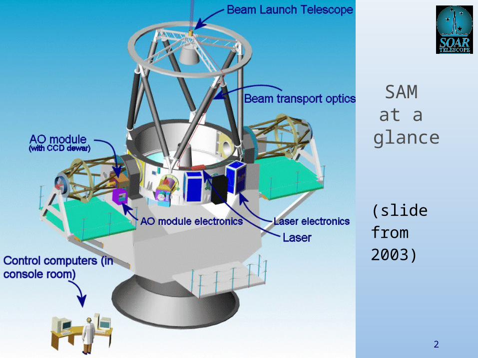
SAM at a
glance
(slidefrom2003)
SAM PDR 3
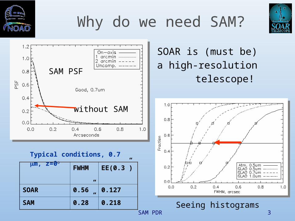
Why do we need SAM?
FWHM EE(0.3”)
SOAR 0.56” 0.127
SAM 0.28” 0.218
Typical conditions, 0.7 m, z=0o
SOAR is (must be) a high-resolution
telescope!SAM PSF
without SAM
Seeing histograms
SAM PDR 4
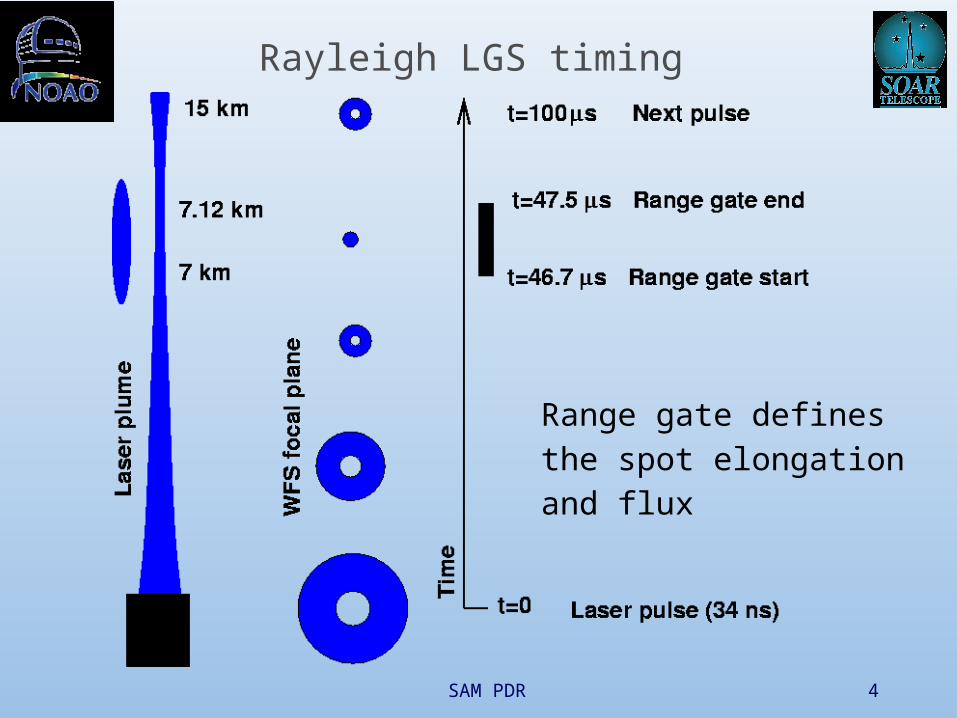
Rayleigh LGS timing
Range gate definesthe spot elongationand flux
SAM PDR 5
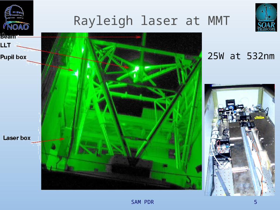
Rayleigh laser at MMT
25W at 532nm

SAM PDR 6
SAM design strategy
Use standard commercial components whenever possible, not custom items
Get a robust system – “set and forget”
Provide margin in performance
SAM PDR 7
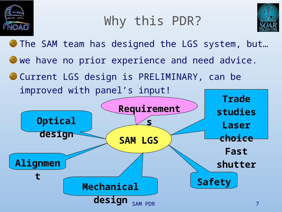
Why this PDR?
The SAM team has designed the LGS system, but…
we have no prior experience and need advice.
Current LGS design is PRELIMINARY, can be improved
with panel’s input!
SAM LGS
Trade studies
Laser choice
Fast shutterOptical design
Alignment
Mechanical design Safety
Requirements

SAM PDR 8
Why a UV laser?UV not visible – no visual hazards
More scattered photons (~- 3)
Easy to separate from the science
Smaller launch telescope
Cheap industrial lasers available: Nd:YAG frequency-tripled, =355nm (material processing)
Less W per $ compared to 532nm
Less efficient optics & detector, absorption in air
Why not?
SAM PDR 9
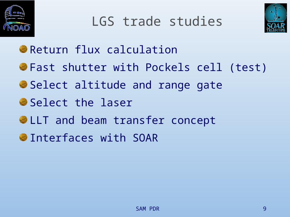
LGS trade studies
Return flux calculation
Fast shutter with Pockels cell (test)
Select altitude and range gate
Select the laser
LLT and beam transfer concept
Interfaces with SOAR

SAM PDR 10
Return flux
Laser power 10W at 355nmLoop time 4.3msSpot elongation 1”
Includes SAM efficiency (0.086), air absorption and density
We need >300 photons!We have them, on paperflux
absorption

SAM PDR 11
Fast shutter – Pockels cell
QX1020 cell
Cleveland Crystals
HV driver from BME

SAM PDR 12
Ringing of the Pockels cell
Centroids of inner spots
are displaced by 9-90 mas
depending on the seeing
After-pulse contains 20% of light
H=7km1” seeing1” elongation

SAM PDR 13
Altitude and range gate
Begin with H=7km and elongation 1” to maximize the flux.Change later if required
SAM PDR 14
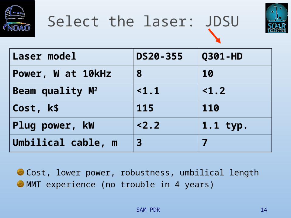
Select the laser: JDSU
Cost, lower power, robustness, umbilical length
MMT experience (no trouble in 4 years)
Laser model DS20-355 Q301-HD
Power, W at 10kHz 8 10
Beam quality M2 <1.1 <1.2
Cost, k$ 115 110
Plug power, kW <2.2 1.1 typ.
Umbilical cable, m 3 7
SAM PDR 15
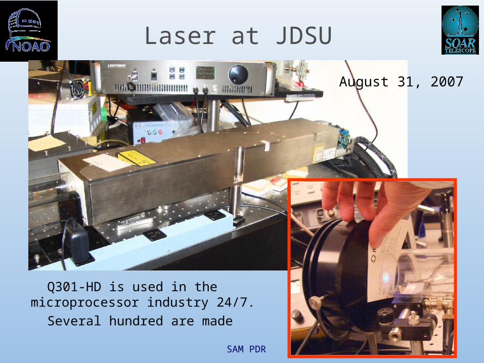
Laser at JDSU
August 31, 2007
Q301-HD is used in the microprocessor industry 24/7.
Several hundred are made
SAM PDR 16
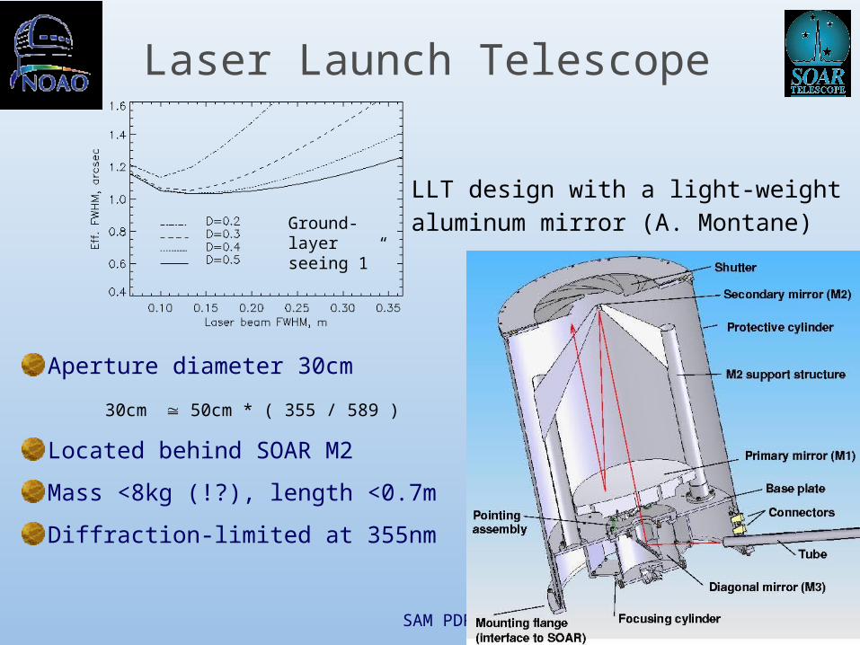
Laser Launch Telescope
Aperture diameter 30cm
30cm 50cm * ( 355 / 589 )
Located behind SOAR M2
Mass <8kg (!?), length <0.7m
Diffraction-limited at 355nm
Ground-layer seeing 1”
LLT design with a light-weightaluminum mirror (A. Montane)
SAM PDR 17
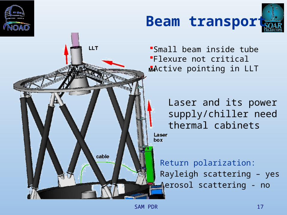
Beam transport
Small beam inside tubeFlexure not criticalActive pointing in LLT
Laser and its power supply/chiller needthermal cabinets
Return polarization:Rayleigh scattering – yesAerosol scattering - no

SAM PDR 18
Laser electronics & chiller
Electronics: 427x363x76mm, 8.4kg, 400W typ.
Chiller: 533x440x264mm, 55kg, 700W typ., horizontal

SAM PDR 19
Beam transport & control
Power and LLT illumination
Pointing on the sky
Beam quality and focus
BEAM CONTROL
SAM PDR 20
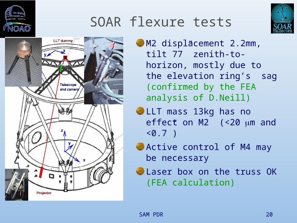
SOAR flexure tests
M2 displacement 2.2mm, tilt 77” zenith-to-horizon, mostly due to the elevation ring’s sag (confirmed by the FEA analysis of D.Neill)
LLT mass 13kg has no effect on M2 (<20m and <0.7”)
Active control of M4 may be necessary
Laser box on the truss OK (FEA calculation)

SAM PDR 21
SOAR-LLT relative flexure
Relative angle between the SOAR optical axis (source at the Nasmyth rotator center, active optics ON) and the LLT is less than +- 5”

SAM PDR 22
Interfaces of LGS with SOAR
Laser box on the SOAR truss
Laser cable goes through regular cable wrap
Laser electronics & chiller in a thermal cabinet
LLT mounted behind M2 at 3 points
Beam duct and relay mirror M4
Safety system
Observatory interlock system

SAM PDR 23
THE END
SAM PDR 24
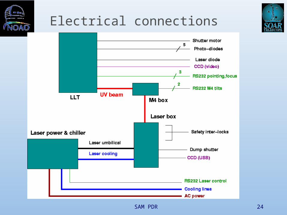
Electrical connections

SAM PDR 25
SAM in numbers
DM Bimorph, 50mm pupil, 60 electrodes
WFS S-H 10x10, CCD-39 pixel 0.37”
Laser Tripled Nd:YAG 355nm, 10W, 10 kHz
LLT D=30cm, behind secondary, H=7km
Gating KD*P Pockels cell, dH=120m
Tip-tilt Two probes, fiber-linked APDs, R<18
Focal plane 3’x3’ square, 3 arcsec/mm, f/16.5
CCD imager 4Kx4K, 0.05” pixels, 6 filters
Coll. space 50mm beam, 100mm along axis

SAM PDR 26
Tip-tilt guiders: the field
4’x4’ surface