samsung r&d institute russia
TRANSCRIPT
2021 International Conference on Indoor Positioning and Indoor Navigation (IPIN), 29 Nov. – 2 Dec. 2021, Lloret de Mar, Spain
Pluto: Motion Detection for Navigation in a VR Headset
Dmitri Kovalenko1
[email protected] Migukin1
[email protected] Ryabkova
[email protected] Chernov1
Samsung R&D Institute Russia
Abstract—Untethered, inside-out tracking is considered a newgoalpost for virtual reality, which became attainable with ad-vent of machine learning in SLAM. Yet computer vision-basednavigation is always at risk of a tracking failure due to poorillumination or saliency of the environment. An extension for anavigation system is proposed, which recognizes agents motionand stillness states with 87% accuracy from accelerometer data.40% reduction in navigation drift is demonstrated in a repeatedtracking failure scenario on a challenging dataset.
Index Terms—inertial navigation, motion detection, deep learn-ing, time series analysis
I. INTRODUCTION
The virtual reality has been a subject of extensive researchfor decades. The advancements in algorithms and hardwarebrought commodity setups to the mass-market. Novel systemsprovide untethered experience, where a user is not constrainedby the cable connecting a headset to a computer. Spatial re-strictions due to the infra-red beacon operation range, inherentin outside-in navigation [1], were removed with the inside-out navigation approach, supported by SLAM (SimultaneousLocalization and Mapping) running onboard, processing stereoor depth camera images, enhanced by sensor fusion withaccelerometer and gyroscope data [2].
Inertial sensors providing an input to a navigation systemenable high-frequency position updates, but are impracticalas a sole data source, as the double integration error accu-mulates [3]. Yet the situation may arise when the camera-based navigation system enters a failure mode due to motionblur, textureless environments, low illumination, occlusions,and rigid world assumption violations. Current headsets haltposition updates until the tracking is reestablished. The userexperience would not have been disrupted if a navigationsystem was equipped with a fallback technique for positionestimates during a tracking failure. A proprioceptive nature ofIMU (Inertial Measurement Unit) makes it a valid candidatefor sensor fusion in SLAM, as wealth of information maybe inferred from its data with help of machine learning. Theproposed method recognizes stillness and motion states ofan agent and sends linear acceleration and velocity pseudo-updates to a navigation system, thus reducing positioningdrift. We named it Pluto. Main contributions are:1 1. Novelmotion detector neural network, based on Temporal Causal
1D. Kovalenko, A. Migukin and V. Chernov made contributions during theirtime in Samsung R&D Institute Russia, but currently are working for Yandex,Huawei and Align Technology respectively.
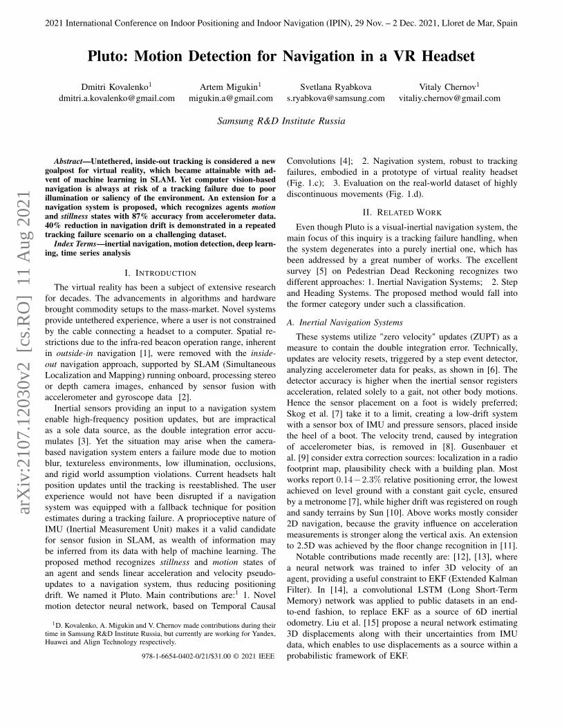
Convolutions [4]; 2. Nagivation system, robust to trackingfailures, embodied in a prototype of virtual reality headset(Fig. 1.c); 3. Evaluation on the real-world dataset of highlydiscontinuous movements (Fig. 1.d).
II. RELATED WORK
Even though Pluto is a visual-inertial navigation system, themain focus of this inquiry is a tracking failure handling, whenthe system degenerates into a purely inertial one, which hasbeen addressed by a great number of works. The excellentsurvey [5] on Pedestrian Dead Reckoning recognizes twodifferent approaches: 1. Inertial Navigation Systems; 2. Stepand Heading Systems. The proposed method would fall intothe former category under such a classification.
A. Inertial Navigation Systems
These systems utilize "zero velocity" updates (ZUPT) as ameasure to contain the double integration error. Technically,updates are velocity resets, triggered by a step event detector,analyzing accelerometer data for peaks, as shown in [6]. Thedetector accuracy is higher when the inertial sensor registersacceleration, related solely to a gait, not other body motions.Hence the sensor placement on a foot is widely preferred;Skog et al. [7] take it to a limit, creating a low-drift systemwith a sensor box of IMU and pressure sensors, placed insidethe heel of a boot. The velocity trend, caused by integrationof accelerometer bias, is removed in [8]. Gusenbauer etal. [9] consider extra correction sources: localization in a radiofootprint map, plausibility check with a building plan. Mostworks report 0.14−2.3% relative positioning error, the lowestachieved on level ground with a constant gait cycle, ensuredby a metronome [7], while higher drift was registered on roughand sandy terrains by Sun [10]. Above works mostly consider2D navigation, because the gravity influence on accelerationmeasurements is stronger along the vertical axis. An extensionto 2.5D was achieved by the floor change recognition in [11].
Notable contributions made recently are: [12], [13], wherea neural network was trained to infer 3D velocity of anagent, providing a useful constraint to EKF (Extended KalmanFilter). In [14], a convolutional LSTM (Long Short-TermMemory) network was applied to public datasets in an end-to-end fashion, to replace EKF as a source of 6D inertialodometry. Liu et al. [15] propose a neural network estimating3D displacements along with their uncertainties from IMUdata, which enables to use displacements as a source within aprobabilistic framework of EKF.978-1-6654-0402-0/21/$31.00 © 2021 IEEE
arX
iv:2
107.
1203
0v2
[cs
.RO
] 1
1 A
ug 2
021
The evolution in ZUPT publications is three-dimensional:1. Stronger neural networks [16]; 2. Cheaper IMU sensors,setups with fewer IMUs; 3. More natural placements [17],head-mounted and hand-held, instead of belt strap-down orshoe mount. The present study is aligned with all threedimensions, utilizing a single low-cost head-mounted IMU fornavigation.
B. Step and Heading Systems
The alternative approach is not to integrate acceleration atall, but to count steps and infer their direction. The foot-mounted sensor boxes are not required in that case, as demon-strated with a belt strap-down in [18]. Goyal et al. deriveheading from 3D attitude, implying only a forward movementof an agent, which might be true for many commuter scenarios,but does not hold for a virtual reality interaction. Jianget al. estimate heading as a direction of spectrally filteredaccelerometer data [19]. A neural network provided an onlinestep length calibration in [20] for a mixed indoor/outdoorcase, where GPS was exploited. Beauregard et al. were amonga few, who also considered a head-mounted setup. Somepedestrian dead reckoning systems rely on an assumptionthat an agent moves only forward, having its orientation andheading always aligned. Windau et al. removes this constraintin their work [21].
The inherent discretisation of the step and heading approachmakes it less enticing for virtual reality, hence we forgo thatin the Pluto navigation system.
C. Action Classification
A coalescent area of research, not being directly involvedwith navigation, is highly relevant: human action classification.Attempts to recognize pedestrian action were conducted withvarious setups: from a minimalistic wristband [22] to a setof 19 IMUs mounted on every part of a human body [23],with 95% F1 score reported by latter with Deep ConvolutionalLSTM for 17 actions classification. Anguita et al. [24] proposea waistband dataset and SVM action classifier performing with89% accuracy. This inquiry was taken further with RecurrentNeural Networks, achieving 94% on the same dataset in [25].
3-class time series classifier was implemented [26], discern-ing a steady walk, rest and irregular motions. Contrary to theabove works, Sun et al. [26] have also demonstrated a waythe classifier influences the navigation system, halting stepcounting during two latter states. A similar classifier was putforward more recently in [27].
The present study went beyond accuracy evaluation, inves-tigating detection delays and intervals between false positives,which provides insights into the system behavior over time.We proceed with detailing the design of navigation systemand motion detector network.
III. PLUTO NAVIGATION SYSTEM
The headset prototype (Fig. 1.c), implementing virtual real-ity capabilities and hosting the online visual-inertial navigationsystem (Pluto) was devised. The orientation estimation system
(b) (c)
−1.5 −1.0 −0.5 0.0 0.5 1.0 1.5 2.0 2.5x, m
−1.0
−0.5
0.0
0.5
1.0
1.5
z, m
Full motion trajectory of a participantGT
(a) (d)Fig. 1. a) An experiment participant taking a backward step b) Thevirtual scene explored by study participants c) The virtual reality headsetprototype; the IMU sensor placement is marked (approximately) by a crossd) A participant movement trajectory in a bird-eye view during the study; noinstructions on a gait pattern were given, except to explore a virtual realityscene naturally
is purely inertial and closely follows [28], using complemen-tary filters with accelerometer and magnetometer data for thetilt and yaw drift correction. The magnetic field is modeled asin [29], with an additional capability to detect magnetic fieldanomalies and recalibrate when necessary. Strong correlationswere registered between IMU temperature and magnitudes ofaccelerometer and gyroscope noise. Instead of random walkbias modeling, the online calibration accumulates samples andsolves for biases for every temperature value (IMU providestemperature measurements at 0.5◦ C increments). Optimalsample sizes are determined accordingly with [30].
The orientation estimation system has shown a competitiveyaw drift of 5◦ per hour, given a low-cost sensor.
The visual-inertial position estimation is a Kalman Filter,with a state consisting of translation and linear velocity as inEq. 1.
µt|t−1 =[tx, vx, ty, vy, tz, vz
]T(1)
The prediction step in Eq. 2 (µ,Σ)t−1|t−1 → (µ,Σ)t|t−1
runs at 500 Hz on accelerometer measurements at, whichhave: 1. Been brought into the world coordinate frame byan orientation estimate; 2. The gravity vector substracted;3. The noise filtered by a high-pass filter.
The filter operates in 3D, but without a loss of generality,Eqs. 2, 3 are formulated in 1D for compactness. F is a statetransition matrix, matrix G maps an acceleration measurementto a state, matrix H maps a state to a velocity measurement.
µt|t−1 = Fµt−1|t−1 +Gat
Σt|t−1 = FΣt−1|t−1FT +GQtG
T
F =
[1 ∆t0 1
]G =
[∆t2
2∆t
]H =
[0 1
] (2)
Qt and Rt are accelerometer and velocity measurementcovariances respectively, maintained as empirical distributionsin a sliding window fashion.
The correction step in Eq. 3 (µ,Σ)t|t−1 → (µ,Σ)t|t usesvelocity vt, supplied by a visual tracker or a motion capturesystem (the latter is the case in experiments, Sec. V-C).
µt|t = µt|t−1 +Kt(vt −Hµt|t−1)
Σt|t = (I −KtH)Σt|t−1
Kt = Σt|t−1HT (HΣt|t−1H
T +Rt)−1
(3)
Timestamps in state subscripts imply that the visual trackerand the IMU run by the aligned clock, which is not true inpractice and moreover, the latency of visual updates varies.The interpolation by agent kinematics would benefit the sys-tem accuracy and may be implemented by e.g. a slidingwindow Kalman Filter, but its practical realization is out ofscope for the present study.
The main proposition is the way acceleration and velocityis provided to the Kalman Filter: at, vt are replaced with zeropseudo-updates 03×1 when the system is in a stilless modeand processed normally otherwise. The mode transitioning isfurther explained.
IV. MOTION DETECTOR
Pluto navigation system transitions to the pseudo-updatemode by virtue of the motion detector, which is a deep neuralnetwork-based two-class classifier, taking a 3D accelerationdata stream as an input and outputting a label {motion,stillness}.
Windows of 3D acceleration data, registered during partic-ipants walking forward, backward, or sideways, regadless ofa head rotating, tilting, or being kept still to the body areconsidered motion. Other windows of 3D acceleration data,when a participant stays still on feet, even if their head rotatesor tilts, are considered stillness.
The input and output tensors are [B, 100, 3] and [B, 1, 2]respectively with dimensions encoding a batch size, timedomain, and data dimensionality. During inference the batchsize is 1 and data are supplied by the sliding-window cache,which shifts by 1 timestamp at consecutive inference calls.
TCN (Temporal Convolutional Network), based on dilatedcausal convolutions, has demonstrated superior performanceon a wide range of sequence modeling tasks [4]. Experiments(Tab. I) show that TCN overperforms baselines accuracy by anotable margin in the accelerometer data classification.
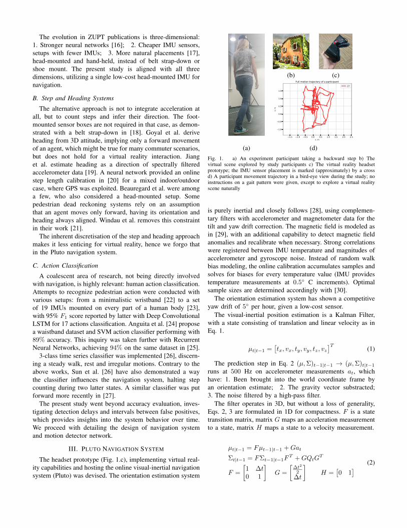
Despite the higher accuracy, TCN is at a disadvantage fromstandpoint of false-positive rate, which is required to be as lowas possible for a virtual reality application. We attribute that tothe TCN output being independent of the network inferenceson previous timestamps. The proposed solution (Fig. 2) stacksTCN with a stateful LSTM, which is fed with TCN logitoutputs, hence explicitly taking the temporal context intoaccount. Networks are trained separately.
4/27/2020 arch.drawio
1/1
LSTM State Tuple
Logits
LogitsLSTM Cell 100
LSTM Cell 100
LSTM Cell 100
TCN Block 200 GT labels
TCN Block 200
TCN Block 200
TCN Block 200
Fig. 2. Pluto motion detector architecture consists of the TCN classifier (blue)and LSTM (purple) for smoothing over the logits. The numbers after blocknames are hidden dimension sizes. The TCN blocks amount and kernel sizewere selected to cover all timestamps in a sliding-window. The input is awindow of 3D acceleration data stream, outputs are likelihoods of possibleagent states: {motion, stillness}.
V. EXPERIMENTS
A thorough evaluation of Pluto navigation system comprisestwo parts: 1. Pluto motion detector classification performanceis studied in comparison with several baselines; 2. Pluto nav-igation system positioning drift is evaluated under conditionsof repeated tracking failures. We proceed with the specificationof collected data, which were made available for the benefitof the research community2.
A. Dataset
The dataset was taken with a headset prototype, spanning30 min in time, where 4 subjects, varying in age and genderwere asked to explore a virtual reality scene, while movingfreely and naturally (Fig. 1.a). During the procudure followingwere collected: 1. IMU data (accelerometer, gyroscope, mag-metometer); 2. 6D positioning ground truth. High-precision6D positioning ground truth data were collected with a motioncapture system OptiTrack® at 125 Hz. The environment forthe study was a well lighted lab room, free of dynamicagents other than a subject. Recorded trajectories are rich withsporadic movements, side- and backward steps, participantslean and change direction and orientation restlessly, rotateand tilt their heads, while observing a virtual reality scene.Data, registered from one of subjects, are held out for testing,remaining data are used in a network training. Such a parti-tioning enables to verify the networks ability to generalize toinputs produced by a previously unseen person.
Experiments with the integrated navigation system(Sec. V-C) were carried out on a testing partition, whichwas split onto 16 sequences of variable length (5 . . . 12 s) atrandom. Each of these tracks is having a simulated trackingfailure introduced, lasting a random time (2 . . . 8 s) at arandom offset from the start. The four tracks shown in Fig. 5are segments of a full sequence from Fig. 1.d.
B. Motion Detection Performance
The agent state classification evaluation starts with a qualita-tive visualization of motion starts and stops, as were registered
2https://github.com/wf34/pluto

40 45 50 55 60 65 70 75Time, s
Stillness
Motion
Motion states over time
GTPluto
Fig. 3. Pluto motion detector output labels in comparison with motion captureground truth labels (GT). A low false positive rate with low detection delaysare demonstrated.
TABLE INEURAL NETWORKS TRAINING AND INFERENCE
Model #weights, M Depth(in blocks)
Train time(per epoch, h)
Train Validation Test
accuracy, % loss accuracy, % loss accuracy, % loss
CNN 2.7 5 0.28 0.899 0.324 0.751 0.702 0.723 1.013LSTM 1.9 4 1.43 0.853 0.473 0.829 0.596 0.820 0.687TCN 1.4 4 0.62 0.948 0.139 0.889 0.304 0.871 0.371Pluto 1.4 + 0.04 4+3 1.55 0.901 0.244 0.811 0.437 0.869 0.376
TCN (a core building block of Pluto) is the best architecture for signal processing ofaccelerometer. Pluto motion detector, which connects TCN to LSTM, trades off a
moderate accuracy loss for a radical false positive rate reduction (Tab. III).
by motion capture and classified by Pluto motion detector ona testing sequence in Fig. 3. Inferred labels do not lag anddemonstrate a low false-positive rate. One nuisance is that thesystem was unable to detect short stops between sequencesof steps in 53 . . . 55, 60 . . . 65 s., due to the participants headstill slightly moving, while the stepping paused. These microstops are included in ground truth class labels, which wereautomatically converted from 6D ground truth trajectories withthe following thresholding on velocity: ‖v‖2 < 0.2 m
s .Networks converge despite a few mislabelings, but label-
ing imperfections also produce outliers in evaluation. Fig. 4shows detection delay histograms for two most competitivealgorithms. Classification time series from Fig. 3 allow toclaim that longer delays (> 5 s) are absent in reality andappear on a figure due to ground truth event mislabelings.
Pluto motion detector is compared to LSTM, CNN, TCN,and a variant [31] of signal processing classic, Otsu thresh-olding [32]. Results in Tab. I suggest that TCN, a corebuilding block of Pluto motion detector, is superior in termsof accuracy, training time and weights amount. The variantof Adaptive Otsu thresholding, which was employed in anevaluation, operates on a 1D signal (a norm of registeredacceleration ||a||2), maintains its histogram and updates athreshold, which splits the histogram into two parts with amaximal inter-class variance. A relation between a currentsample and the threshold value is used for classification.
All evaluated networks were trained with a 3D signal, which
TABLE IIMOTION DETECTION METRICS
Method Accuracy Precision Recall F1
Otsu 0.746 0.758 0.745 0.752Pluto 0.874 0.825 0.960 0.887
Pluto motion detector shows a superior classification performance to the baseline on adataset testing partition (Sec. V-B).
is a registered acceleration in the global coordinate frame.TCN and CNN networks were trained with Adam optimizer,LSTM with RMSProp and the cross-entropy loss was usedfor all. The hyperparameter choice (the sliding window sizeof 100 timestamps = 0.2 s) was done by a grid search (withboundaries 0.05 . . . 3 s) on a training partition with the baselineCNN network. All networks were implemented in Tensorflow,underwent several iterations of coarse-to-fine tuning, haveapproximately the same size and were trained for the sametime. The times per epoch in Tab. I were registered for CPUtraining at 20 cores on Intel Xeon E5. Pluto motion detectorinference is tangible for realtime running on the headsetprototype at a decreased frequency (10 Hz).
The achieved accuracy of 87% (Tab. II) could have beenimproved by the dataset increase, due to movements of thetest subject (and their IMU accelerations) laying outside of anetwork domain, because only a small set of anthropometri-cally different study subjects comprise the training partition.Nonetheless, network overfitting was avoided, which evi-dences from accuracy being approximately equal on trainingand testing dataset partitions.
Attempted network training approaches, which have shownno classification improvement are: data augmentation by affinetransformations, input dimensionality extension by gyroscopeand magnetic data, pretraining on synthetic3 accelerations.
User experience tests in virtual reality have shown a lowcorrelation with the accuracy metric because the temporalcontext is not captured: the metric value is the same, whethera detection is off just by a one timestamp or 50. To adjustfor that, an additional performance evaluation was conductedwith [33]: 1. Mean detection delay; 2. Mean interval betweenfalse-positive detections. These metrics, contrary to accuracy,precision, recall, F1 are in a temporal domain. The detectiondelay is a time in seconds since a labeled ground truth eventuntil its true positive detection, issued by the detector. Theinterval between false positive detections is a time in secondsbetween consecutive detections, issued by the detector and nothaving labeled ground truth events corresponding to them.
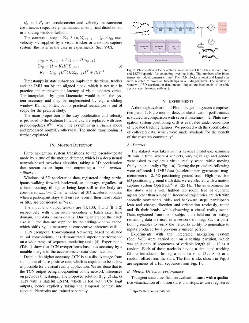
Due to Tab. III, Pluto motion detector issues false positivedetections 4 times less often than Otsu on average, while hasapproximately same true positive detection delays. To captureresults beyond a mean and variance, the histogram of motionstart detection delays is shown in Fig. 4.
A sizable variance in metric magnitudes is found in Tab. III.It is due to the fact that neural network sensitivity is hard to
3https://github.com/Aceinna/gnss-ins-sim
0 2 4 6 80
2
4
6
8
10
12Motion Start Delay Distribution
PlutoOtsu
Events, #
Time, s
Fig. 4. Histogram of delays in detecting a motion start, [sec]. Pluto motiondetector shows more low-delay events when compared to adaptive Otsuthresholding. Outliers in a right part of the domain were addressed in Sec. V-B
TABLE IIIMOTION DETECTION PERFORMANCE, [SEC]
Method Starts Detection Stops DetectionDetection Delayl Interval
betweenfalse positivesh
Detection Delayl Intervalbetweenfalse positivesh
µ σ µ σ µ σ µ σ
Otsu 2.409 2.324 8.856 12.013 1.435 1.205 11.060 10.829CNN 2.634 17.182 0.487 0.890 0.316 0.568 0.492 0.881LSTM 0.292 0.346 0.188 0.431 0.252 0.246 0.188 0.429TCN 1.893 1.935 2.125 2.969 1.071 1.195 2.160 3.242Pluto 2.389 2.128 14.889 18.425 1.771 1.427 40.093 48.488
Pluto motion detector shows low detection delays and high intervals between falsealarms, outperforming competitors in MDD
MFPI for start and stop events both. l meanslower is better; h means higher is better.
adjust: LSTM has converged to be very sensitive to signalchanges while producing more false positives, while TCN isless prone to false positive detections, but results in longerdelays. The proposed motion detector Pluto combines advan-tages of both, enabling the higher responsiveness with fewerfalse positives.
C. Effects of Motion Detection on Navigation
The motion detector capable of discerning an agents still-ness and motion may benefit a navigation system, as proposedin Sec. III. The claim is evaluated in simulated experiments,conducted on 16 sequences, taken from testing data, as de-scribed in Sec. V-A. The navigation system is a Kalmanfilter, with prediction steps by IMU acceleration and correctionsteps by linear velocity. Velocity and orientation estimates areprovided by a motion capture system. Velocity updates are notprovided during a simulated tracking failure.
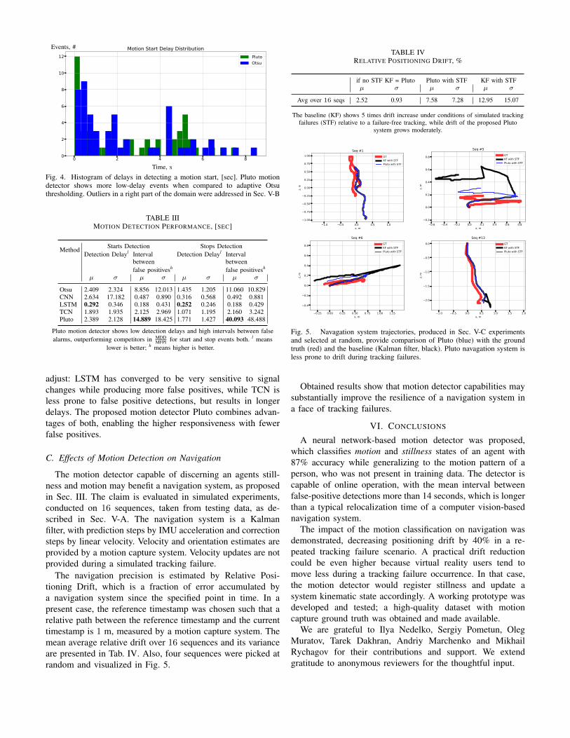
The navigation precision is estimated by Relative Posi-tioning Drift, which is a fraction of error accumulated bya navigation system since the specified point in time. In apresent case, the reference timestamp was chosen such that arelative path between the reference timestamp and the currenttimestamp is 1 m, measured by a motion capture system. Themean average relative drift over 16 sequences and its varianceare presented in Tab. IV. Also, four sequences were picked atrandom and visualized in Fig. 5.
TABLE IVRELATIVE POSITIONING DRIFT, %
if no STF KF = Pluto Pluto with STF KF with STFµ σ µ σ µ σ
Avg over 16 seqs 2.52 0.93 7.58 7.28 12.95 15.07
The baseline (KF) shows 5 times drift increase under conditions of simulated trackingfailures (STF) relative to a failure-free tracking, while drift of the proposed Pluto
system grows moderately.
−1.0 −0.5 0.0 0.5 1.0x, m
−1.00
−0.75
−0.50
−0.25
0.00
0.25
0.50
0.75
1.00
z, m
Seq #1GTKF with STFPluto with STF
−0.6 −0.4 −0.2 0.0 0.2 0.4 0.6 0.8x, m
−0.2
0.0
0.2
0.4
0.6
0.8
z, m
Seq #5GTKF with STFPluto with STF
−0.25 0.00 0.25 0.50 0.75 1.00 1.25x, m
−0.4
−0.2
0.0
0.2
0.4
0.6
0.8
z, m
Seq #6GTKF with STFPluto with STF
−1.0 −0.5 0.0 0.5 1.0 1.5 2.0x, m
−2.0
−1.5
−1.0
−0.5
0.0
z, m
Seq #13GTKF with STFPluto with STF
Fig. 5. Navagation system trajectories, produced in Sec. V-C experimentsand selected at random, provide comparison of Pluto (blue) with the groundtruth (red) and the baseline (Kalman filter, black). Pluto navagation system isless prone to drift during tracking failures.
Obtained results show that motion detector capabilities maysubstantially improve the resilience of a navigation system ina face of tracking failures.
VI. CONCLUSIONS
A neural network-based motion detector was proposed,which classifies motion and stillness states of an agent with87% accuracy while generalizing to the motion pattern of aperson, who was not present in training data. The detector iscapable of online operation, with the mean interval betweenfalse-positive detections more than 14 seconds, which is longerthan a typical relocalization time of a computer vision-basednavigation system.
The impact of the motion classification on navigation wasdemonstrated, decreasing positioning drift by 40% in a re-peated tracking failure scenario. A practical drift reductioncould be even higher because virtual reality users tend tomove less during a tracking failure occurrence. In that case,the motion detector would register stillness and update asystem kinematic state accordingly. A working prototype wasdeveloped and tested; a high-quality dataset with motioncapture ground truth was obtained and made available.
We are grateful to Ilya Nedelko, Sergiy Pometun, OlegMuratov, Tarek Dakhran, Andriy Marchenko and MikhailRychagov for their contributions and support. We extendgratitude to anonymous reviewers for the thoughtful input.
REFERENCES
[1] D. R. Colomer, G. Lopes, D. Kim, C. Honnet, D.Moratal, and A. Kampff. “HIVE Tracker: a tiny, low-cost, and scalable device for sub-millimetric 3D posi-tioning”. In: Augmented Human 9 (2018), pp. 1–8.
[2] E. S. Jones and S. Soatto. “Visual-inertial navigation,mapping and localization: A scalable real-time causalapproach”. In: The International Journal of RoboticsResearch 30.4 (2011), pp. 407–430.
[3] C. Verplaetse. “Inertial proproceptive devices: Self-motion-sensing toys and tools”. In: IBM Systems Jour-nal 35.3.4 (1996), pp. 639–650.
[4] S Bai, J. Kolter, and V Koltun. “An empirical evaluationof generic convolutional and recurrent networks forsequence modeling. arXiv 2018”. In: arXiv preprintarXiv:1803.01271 ().
[5] R. Harle. “A survey of indoor inertial positioningsystems for pedestrians.” In: IEEE CommunicationsSurveys and Tutorials 15.3 (2013), pp. 1281–1293.
[6] L. Xiaofang, M. Yuliang, X. Ling, C. Jiabin, and S.Chunlei. “Applications of zero-velocity detector andKalman filter in zero velocity update for inertial navi-gation system”. In: Guidance, Navigation and ControlConference (CGNCC). IEEE. 2014, pp. 1760–1763.
[7] I. Skog, J.-O. Nilsson, and P. Händel. “Evaluation ofzero-velocity detectors for foot-mounted inertial nav-igation systems”. In: Indoor Positioning and IndoorNavigation (IPIN). IEEE. 2010, pp. 1–6.
[8] R. Feliz, E. Zalama, and J. Gómez-García-Bermejo.“Pedestrian Tracking Using Inertial Sensors”. In: Jour-nal of Physical Agents 3 (Jan. 2009). DOI: 10.14198/JoPha.2009.3.1.05.
[9] D. Gusenbauer, C. Isert, and J. Krösche. “Self-containedindoor positioning on off-the-shelf mobile devices”. In:Indoor positioning and indoor navigation (IPIN). IEEE.2010, pp. 1–9.
[10] X. Sun, K. Wu, Y. Li, and K. Di. “A Zupt-Based Methodfor Astronaut Navigation on Planetary Surface andPerformance Evaluation under Different LocomotionPatterns”. In: ISPRS - International Archives of the Pho-togrammetry, Remote Sensing and Spatial InformationSciences XL-4 (Mar. 2014), p. 239. DOI: 10 . 5194 /isprsarchives-XL-4-239-2014.
[11] M. G. Puyol, D. Bobkov, P. Robertson, and T. Jost.“Pedestrian simultaneous localization and mapping inmultistory buildings using inertial sensors”. In: IEEETransactions on Intelligent Transportation Systems 15.4(2014), pp. 1714–1727.
[12] S. Cortés, A. Solin, and J. Kannala. “Deep LearningBased Speed Estimation for Constraining StrapdownInertial Navigation on Smartphones”. In: IEEE 28thInternational Workshop on Machine Learning for SignalProcessing (MLSP). IEEE. 2018, pp. 1–6.
[13] T. Feigl, S. Kram, P. Woller, R. H. Siddiqui, M.Philippsen, and C. Mutschler. “RNN-aided human ve-
locity estimation from a single IMU”. In: vol. 20.13. Multidisciplinary Digital Publishing Institute, 2020,p. 3656.
[14] J. P. Silva do Monte Lima, H. Uchiyama, and R.-i.Taniguchi. “End-to-End Learning Framework for IMU-Based 6-DOF Odometry”. In: Sensors 19.17 (2019),p. 3777.
[15] W. Liu, D. Caruso, E. Ilg, J. Dong, A. I. Mourikis,K. Daniilidis, V. Kumar, and J. Engel. “TLIO: TightLearned Inertial Odometry”. In: IEEE Robotics andAutomation Letters 5.4 (2020), pp. 5653–5660.
[16] B. Wagstaff and J. Kelly. “LSTM-based zero-velocitydetection for robust inertial navigation”. In: 2018 Inter-national Conference on Indoor Positioning and IndoorNavigation (IPIN). IEEE. 2018, pp. 1–8.
[17] H. Yan, Q. Shan, and Y. Furukawa. “RIDI: RobustIMU double integration”. In: Proceedings of the Eu-ropean Conference on Computer Vision (ECCV). 2018,pp. 621–636.
[18] P. Goyal, V. J. Ribeiro, H. Saran, and A. Kumar. “Strap-down pedestrian dead-reckoning system”. In: IndoorPositioning and Indoor Navigation (IPIN). IEEE. 2011,pp. 1–7.
[19] W. Jiang and Z. Yin. “Human tracking using wearablesensors in the pocket”. In: IEEE Global Conference onSignal and Information Processing (GlobalSIP). IEEE.2015, pp. 958–962.
[20] S. Beauregard. “A helmet-mounted pedestrian deadreckoning system”. In: 3rd International Forum onApplied Wearable Computing (IFAWC). VDE. 2006,pp. 1–11.
[21] J. Windau and L. Itti. “Walking compass with head-mounted IMU sensor”. In: 2016 IEEE InternationalConference on Robotics and Automation (ICRA). IEEE.2016, pp. 5542–5547.
[22] M. Gjoreski, H. Gjoreski, M. Luštrek, and M. Gams.“Recognizing atomic activities with wrist-worn ac-celerometer using machine learning”. In: Proceedingsof the 18th International Multiconference InformationSociety (IS), Ljubljana, Slovenia. 2015, pp. 10–11.
[23] F. J. Ordóñez and D. Roggen. “Deep convolutional andlstm recurrent neural networks for multimodal wearableactivity recognition”. In: Sensors 16.1 (2016), p. 115.
[24] D. Anguita, A. Ghio, L. Oneto, X. Parra, and J. Reyes-Ortiz. “Human Activity Recognition on SmartphonesUsing a Multiclass Hardware-Friendly Support VectorMachine”. In: vol. 7657. Dec. 2012, pp. 216–223. ISBN:978-3-642-35394-9. DOI: 10.1007/978-3-642-35395-6_30.
[25] LSTMs for Human Activity Recognition. 2018. URL:https://github.com/guillaume-chevalier/LSTM-Human-Activity-Recognition (visited on 05/31/2018).
[26] Z. Sun, X. Mao, W. Tian, and X. Zhang. “Activ-ity Classification and Dead Reckoning for PedestrianNavigation with Wearable Sensors”. In: Measurement
Science and Technology 20 (Nov. 2008), p. 015203.DOI: 10.1088/0957-0233/20/1/015203.
[27] J. Rantanen, M. Makela, L. Ruotsalainen, and M.Kirkko-Jaakkola. “Motion Context Adaptive Fusion ofInertial and Visual Pedestrian Navigation”. In: Sept.2018, pp. 206–212. DOI: 10.1109/IPIN.2018.8533872.
[28] S. M. LaValle, A. Yershova, M. Katsev, and M.Antonov. “Head tracking for the Oculus Rift”. In:International Conference on Robotics and Automation(ICRA). IEEE. 2014, pp. 187–194.
[29] T. Ozyagcilar. “Calibrating an ecompass in the presenceof hard and soft-iron interference”. In: Freescale Semi-conductor Ltd (2012), pp. 1–17.
[30] A. Foi, V. Katkovnik, and K. Egiazarian. “Point-wise shape-adaptive DCT for high-quality denoisingand deblocking of grayscale and color images”. In:IEEE Transactions on Image Processing 16.5 (2007),pp. 1395–1411.
[31] A Migukin, D Kovalenko, S Ryabkova, and V Chernov.Method and device for strap down inertial navigation.RU Patent 2685767C1, 2018.08.13.
[32] N. Otsu. “A threshold selection method from gray-levelhistograms”. In: IEEE transactions on systems, man,and cybernetics 9.1 (1979), pp. 62–66.
[33] Detection of abrupt changes: theory and application.Prentice Hall Englewood Cliffs.